

Page 1
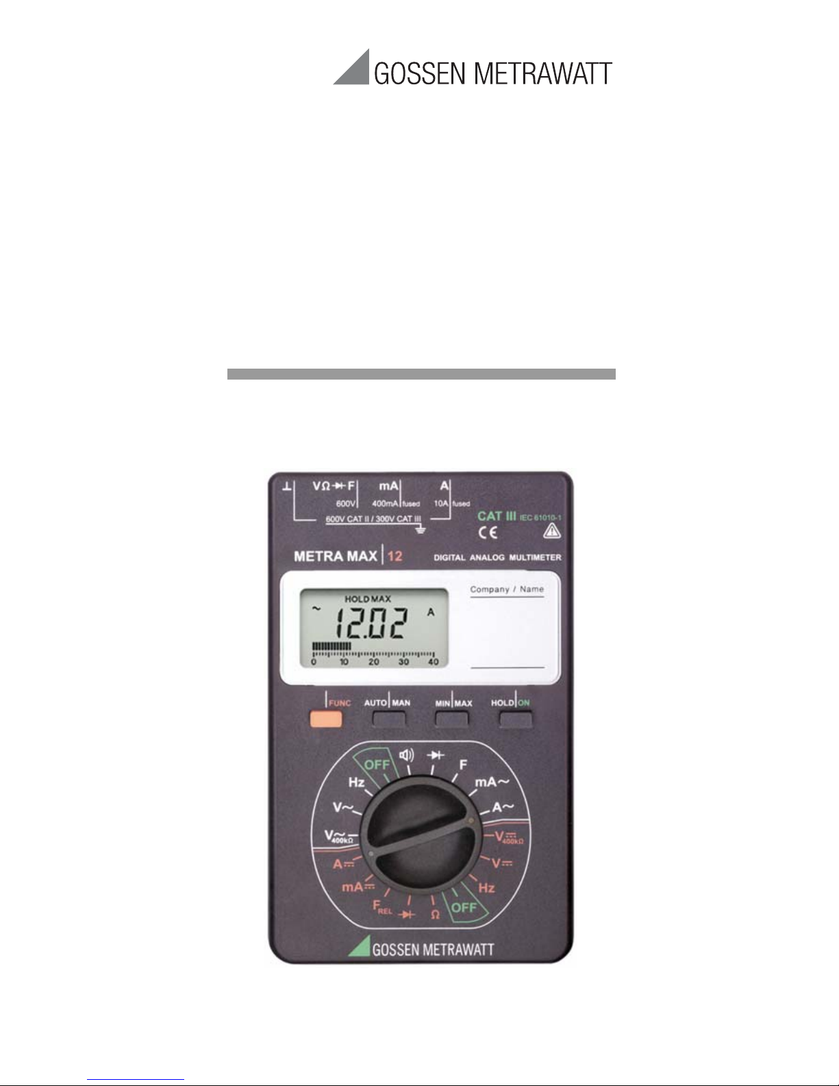
METRA MAX12
Analog-Digital Multimeter
Operating Instructions
3-348-820-02
18/6.17
Page 2
2 GMC-I Messtechnik GmbH
2
1
34
6
789
10
11
MAN
AUTO
Hz
k
n
i
u
M
mVA
F
HOLD MAX MIN
403020100
REL
5
F
Hz
mA
A
V
V
400k
OFF
F
V
HOLD/ONMIN/MAXAUTO/MAN
Hz
mA
A
OFF
V
MAN
AUTO
Hzk
niu
M
mVA
F
HOLD
MAX
MIN
403020100
REL
400k
REL
2
5
1
3
4
7
6
FUNC
mA
600V
AVF
600 V CAT II / 300 V CAT I II
400mA fused 10A fused
max.
600 V !
Page 3

GB
GMC-I Messtechnik GmbH 3
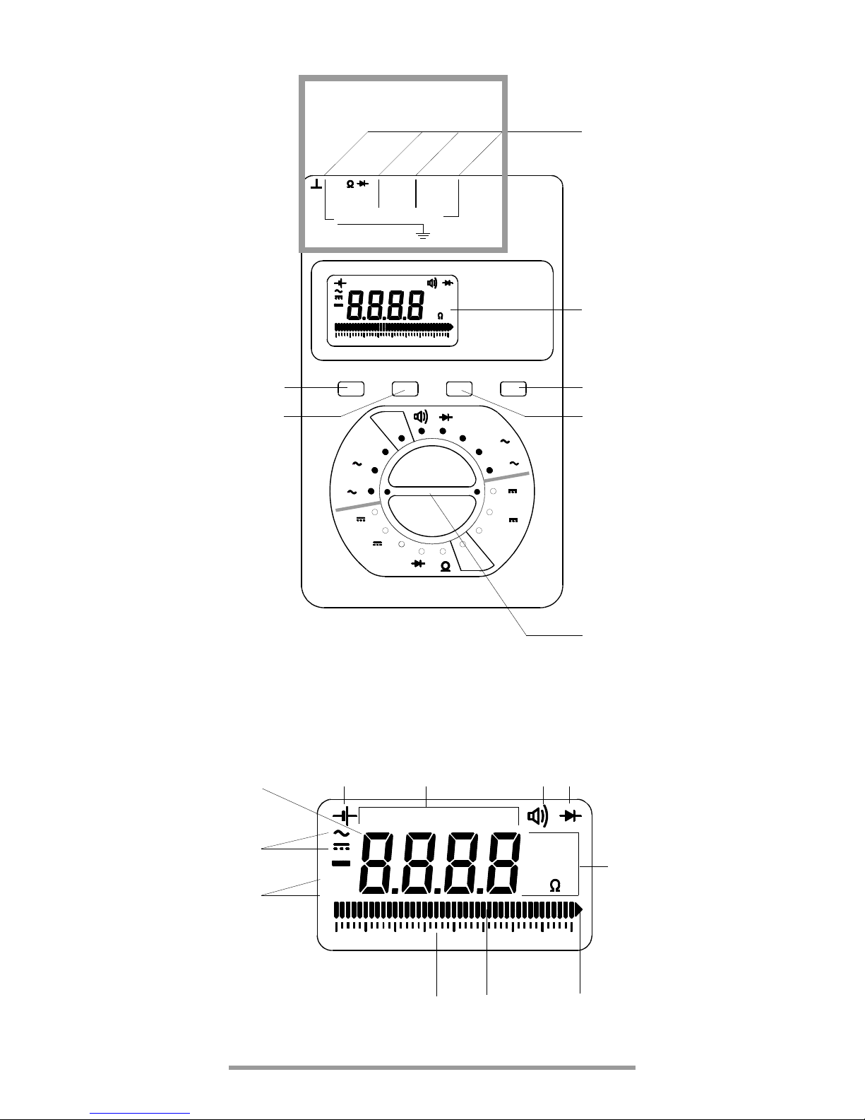
Operating and Connector Elements
1 Connector Jacks
2LCD Display
3 HOLD/ON: Measurement Value Storage Key / On Switch
4 MIN/MAX: Key for Storage of Minimum or Maximum Value
5 Selector Switch for OFF and Measurement Function Selection
6 AUTO/MAN: Key for Manual Measurement
7 Multifunction Key
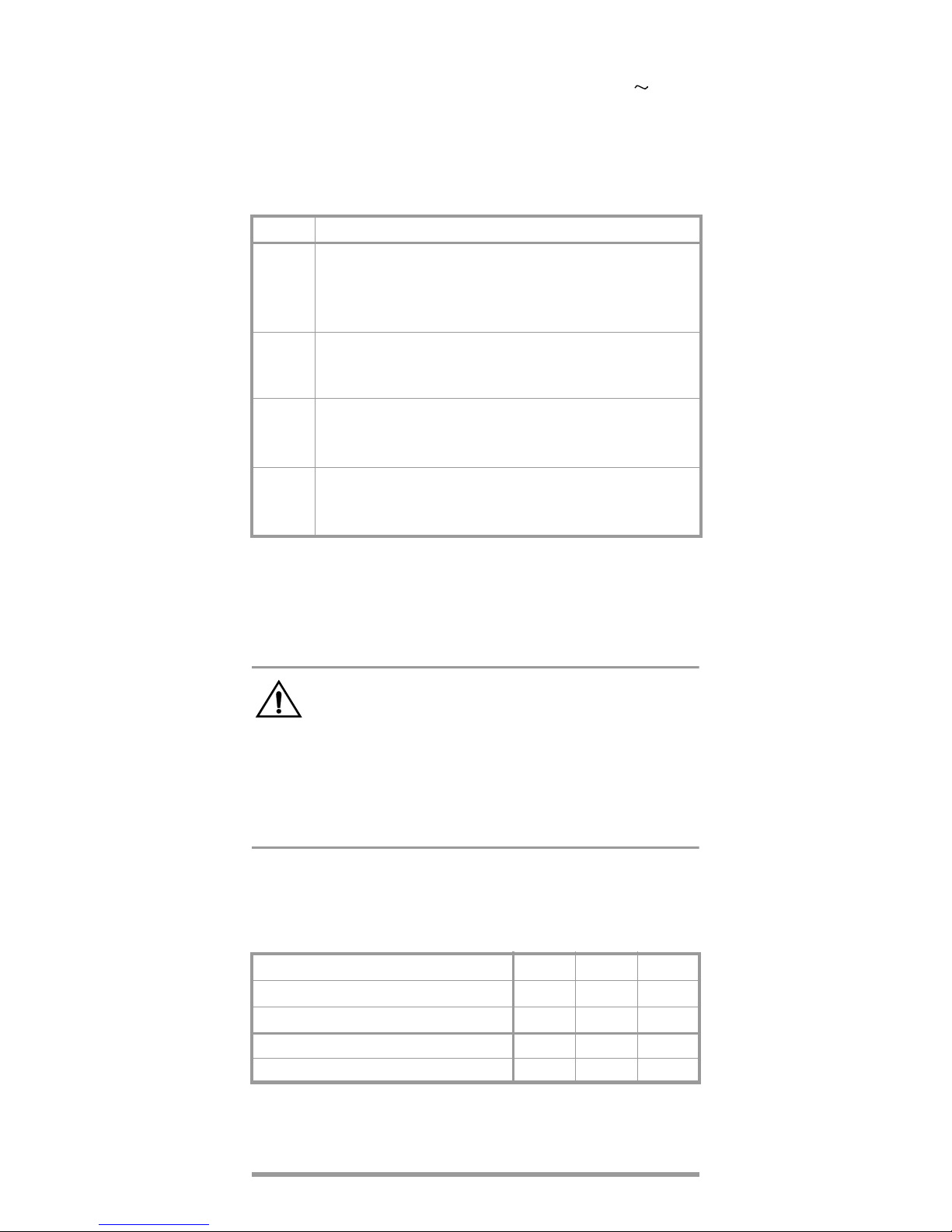
Display
1 Digital Display with Decimal Point and Polarity Indicator
2 Low Battery Display
3 REL, HOLD, and MIN and MAX Display
4 Continuity Test Display:
Loudspeaker symbol appears when acoustic signal is activated
5 Diode Measurement Display
6 Unit of Measure Display
7 Exceeded Measuring Range Display
8 Pointer for Analog Display
9 Analog Display Scale
10 Display for Manual or Automatic Measuring Range Selection
11 Display of Selected Current Type
Page 4

4 GMC-I Messtechnik GmbH
Contents Page
1 Safety Features and Precautions . . . . . . . . . . . . . 5
2 Initial Start-Up . . . . . . . . . . . . . . . . . . . . . . . . . . . . 8
3 Selecting Measuring Functions and Ranges . . . . . 8
3.1 Measuring Function Selection . . . . . . . . . . . . . . . . . 8
3.2 Automatic Measuring Range Selection . . . . . . . . . . . 9
3.3 Manual Measuring Range Selection . . . . . . . . . . . . . 9
3.4 Quick Measurements . . . . . . . . . . . . . . . . . . . . . . . . 9
4 LCD Display . . . . . . . . . . . . . . . . . . . . . . . . . . . . . 10
4.1 Digital Display . . . . . . . . . . . . . . . . . . . . . . . . . . . . 10
4.2 Analog Display . . . . . . . . . . . . . . . . . . . . . . . . . . . 10
5 Acoustic Signal . . . . . . . . . . . . . . . . . . . . . . . . . . 10
6 Measurement Value Storage “HOLD” . . . . . . . . . 10
7 Storing Minimum or Maximum Values
“MIN/MAX” Hold . . . . . . . . . . . . . . . . . . . . . . . . . 11
8 Voltage Measurement . . . . . . . . . . . . . . . . . . . . . 12
9 Current Measurement . . . . . . . . . . . . . . . . . . . . . 13
9.1 AC Measurement with (Clip-On) Current
Transformers . . . . . . . . . . . . . . . . . . . . . . . . . . . . 14
10 Continuity Testing and Resistance Measurement 15
11 Diode Testing . . . . . . . . . . . . . . . . . . . . . . . . . . . 16
12 Capacitance Measurement . . . . . . . . . . . . . . . . . 17
13 Frequency Measurement . . . . . . . . . . . . . . . . . . 18
14 Characteristic Values . . . . . . . . . . . . . . . . . . . . . 19
15 Maintenance . . . . . . . . . . . . . . . . . . . . . . . . . . . . 23
15.1 Battery . . . . . . . . . . . . . . . . . . . . . . . . . . . . . . . . . 23
15.2 Fuses . . . . . . . . . . . . . . . . . . . . . . . . . . . . . . . . . . 24
15.3 Housing . . . . . . . . . . . . . . . . . . . . . . . . . . . . . . . . 25
15.4 Recalibration . . . . . . . . . . . . . . . . . . . . . . . . . . . . . 26
16 Product Support . . . . . . . . . . . . . . . . . . . . . . . . . 26
17 Repair and Replacement Parts Service
Calibration Center and Rental Instrument Service 27
Page 5

GB
GMC-I Messtechnik GmbH 5
1 Safety Features and Precautions
You have selected an instrument which provides you with a
high level of safety.
This instrument fulfills the requirements of the applicable
EU guidelines and national regulations. We confirm this
with the CE marking. The relevant declaration of conformity
can be obtained from GMC-I Messtechnik GmbH.
The instrument is manufactured and tested in accordance
with safety regulations IEC 61010–1:2010/DIN EN 61010–
1:2011/VDE 0411–1:2011. When properly used, safety of
the operator, as well as that of the instrument, is assured.
Their safety is however not guaranteed, if the instrument is
used improperly or handled carelessly.
In order to maintain flawless technical safety conditions, and to
assure safe use, it is imperative that you read the operating
instructions thoroughly and carefully before placing your instrument into service, and that you follow all instructions contained
therein.
Observe the following safety precautions:
• The instrument may only be operated by persons who
are capable of recognizing contact hazards and taking
the appropriate safety precautions. Contact hazards
exist anywhere, where voltages of greater than 33 V may
occur (effective value).
• Avoid working alone when taking measurements which
involve contact hazards. Be certain that a second person
is present.
• The maximum allowable voltage between any given connector
jack (1) and earth is equal to 600 V CAT II.
• Be prepared for the occurrence of unexpected voltages
at devices under test (e.g. defective devices). For example, capacitors can be dangerously charged.
• Make certain that the measurement cables are in flaw-
less condition, e.g. no damage to insulation, no interruptions in cables or plugs etc.
• No measurements may be made with this instrument in
electrical circuits with corona discharge (high-voltage).
• Special care is required when measurements are made
in HF electrical circuits. Dangerous pulsating voltages
may be present.
• Measurements under moist ambient conditions are not
allowable.
• Be absolutely certain that the measuring ranges are not
overloaded beyond their allowable capacities. Limit values can be found in the table “Measuring Ranges” in
chapter 14 "Characteristic Values".
Page 6
6 GMC-I Messtechnik GmbH
• All current ranges are equipped with fuses. The maxi-
mum allowable voltage for the measuring current circuit
(= nominal voltage of the fuse) is equal to 600 V .
• The device may only be used for measurements of category
CAT II 600 V or CAT III 300 V. Please refer to the table of measuring categories below regarding the range of application.
Measuring Categories and their Meaning per IEC 61010-1
The measurement category and the relevant maximum
rated voltage (e. g. 300 V CAT III) which are shown on the
instrument casing apply to your measuring instrument.
Application of cable set KS17-2
Attention!
Please observe the maximum values of the electrical
safety of the device.
In conformity with standard DIN EN 61010-031,
measurements in an environment according to
measuring category III and IV may only be performed with the safety cap applied to the test
probe of the measurement cable.
For establishing contact in 4 mm jacks you have to remove
the safety cap by levering out the snap lock of the safety
cap with another sharp object (e.g. the second test probe).
Electrical Safety of cable set KS17-2
CAT Definition
I
Measurements in electrical circuits not directly connected
to the mains system:
e. g. power systems in motor vehicles or aeroplanes,
batteries ...
II
Measurements in electrical circuits directly connected to
the low-voltage system: via plug, e.g. in households,
offices, laboratories ...
III
Measurements in facility installations:
stationary consumers, distributor connections, devices
attached to a distributor
IV
Measurements at the source of low-voltage installations:
Meters, main terminal, primary overcurrent protection
devices
Maximum Rated Voltage
600 V 1000 V
1000 V
Measuring Category
CAT IV CAT I I I CAT II
Maximum Rated Current 1 A 1 A 16 A
with safety cap applied —
without safety cap applied — —
Page 7
GB
GMC-I Messtechnik GmbH 7
–
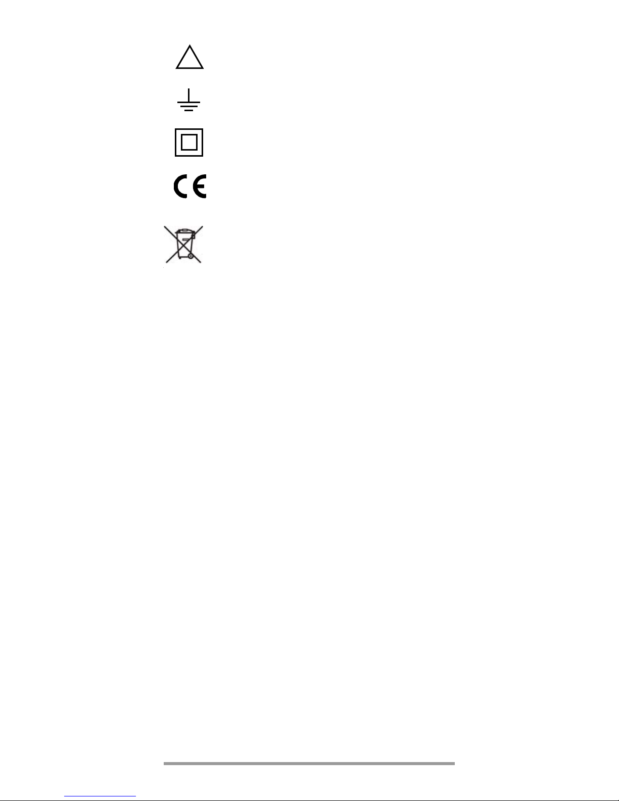
Meaning of symbols on the instrument
Warning concerning a point of danger
(Attention: observe documentation)
Earth
Continuous, doubled or reinforced
insulation
Indicates EU conformity
This device may not be disposed of with the trash.
Further information regarding the WEEE mark can be
accessed on the Internet at www.gossenmetrawatt.com
by entering the search term ’WEEE’.
Repair, Parts Replacement and Balancing
When the instrument is opened, voltage conducting parts
may be exposed. The instrument must be disconnected
from the measuring circuit for repair, replacement of parts
or balancing. If repair or balancing of a live, open instrument is required, this may only be carried out by trained
personnel who are familiar with the dangers involved.
Errors and Extraordinary Strains
If it may be assumed that the instrument can no longer be
operated safely, it must be removed from service and
secured against unintentional use.
Safe operation can no longer be relied upon,
• if the instrument demonstrates visible damage,
• if the instrument no longer functions,
• after a long period of storage under unfavorable condi-
tions.
!
Page 8
8 GMC-I Messtechnik GmbH
2 Initial Start-Up
Battery
The instrument is delivered in operational condition with
batteries installed.
Please see chapter 15.1, page 23, before initial start-up of
your instrument, or after a lengthy period of storage.
Switching the Instrument On
➭ Turn the selector switch from the OFF position to the
desired measuring range.
An acoustic signal acknowledges that the instrument has
been switched on. All of the LCD elements are activated
briefly. A drawing of the LCD can be found on page 2.
Note!
Electrical discharge and high frequency interference can cause incorrect displays, and may
block the measuring sequence. To reset, switch
the instrument off, and then back on. If this procedure is unsuccessful, briefly disconnect the
battery from the contact terminals.
Attention!
Before opening, disconnect the instrument from
the measuring circuit and observe chapter 15,
page 23!
Automatic Shut-Down
Your instrument switches itself off automatically after
30 minutes, if no keys or the selector switch have been
activated during this time.
Switching the Instrument back On
➭ Activate the HOLD/ON key. Press briefly twice.
Switching the Instrument Off
➭ Turn the selector switch to the OFF position.
3 Selecting Measuring Functions and Ranges
3.1 Measuring Function Selection
The desired measuring function is selected with the selector switch (white or colored printing). In order to select the
function printed in color, the multifunction key must also be
pressed. If the multifunction key is pressed again, the function printed in white is reactivated.
Page 9
GB
GMC-I Messtechnik GmbH 9
3.2 Automatic Measuring Range Selection
These multimeters are equipped with automatic measuring
range selection for all measuring ranges except for the
ranges 400 mV and 10 A. Automatic selection is functional as soon as the instrument has been switched on.
The instrument automatically selects the measuring range
in accordance with the applied measuring magnitude,
which provides for optimum resolution.
The instrument switches automatically to:
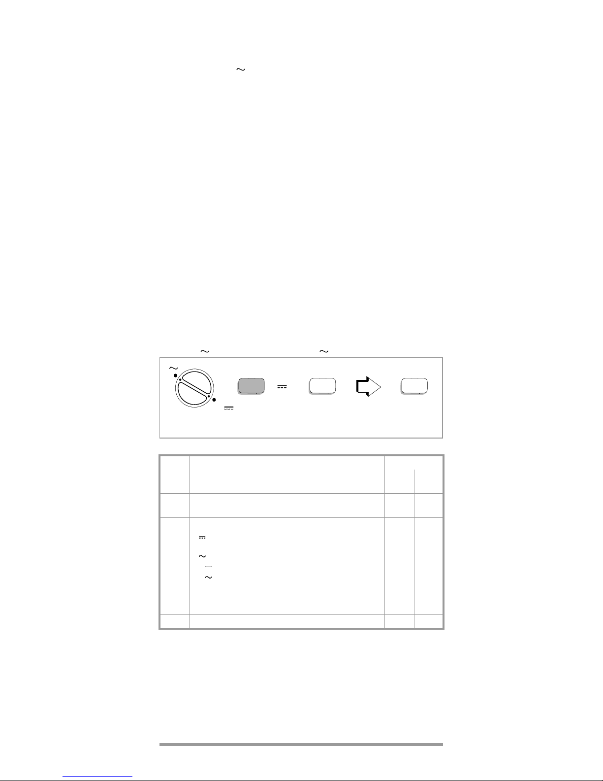
3.3 Manual Measuring Range Selection
You can deactivate automatic measuring range selection
and select and define the ranges manually in accordance
with the following table.
➭ First select the desired measuring function with the
selector switch and, if appropriate, the multifunction key.
➭ Briefly activate the AUTO/MAN key.
Manual operation is deactivated if you press and hold the
AUTO/MAN key until you hear a second acoustic signal,
and the display switches from MAN to AUTO.
When switching back to automatic operation in the
400 mV range occurs, the 4 V range is activated.
3.4 Quick Measurements
If you wish to perform quicker measurements than those
possible with the automatic measuring range selection
function, the appropriate measuring range must be fixed by
the function “Manual Meas. Range Selection”, see above.
the next highest range at (3999 D + 1 D)
the next lowest range at (380 D – 1 D)
AUTO/
MAN
Function
Acknowledgement
Display
Acoust.
Signal
Brief
Manual Operation ON:
Measuring Range is defined
MAN 1 x
Brief
Switching Sequence at:
V : 400 mV V 40 V 400 V 600 V
400 mV 4V ...
V/: 4V 40 V 400 V 600 V 400 mV ...
mA : 40 mA 400 mA 40 mA ...
mA /: 40 mA 400 mA 40 mA
...
:40M 400 4k 40 k400k
4000 k 40 M ...
F : 4 nF 40 nF 400 nF 4 F 40 F ...
MAN 1 x
Long Return to Automatic Range Selection AUTO 2 x
V
AUTO/MAN AUTO/MAN
V
V
Example: manual meas. range selection for volts DC
Page 10

10 GMC-I Messtechnik GmbH
4LCD Display
4.1 Digital Display
The digital display shows the measurement value, decimal
point and sign. The selected unit of measure and type of
current are displayed. A minus sign appears in front of the
digits for the measurement of direct magnitudes, if the
positive pole of the measurement magnitude is applied to
the “” input. A blinking “4000” appears if the measuring
range upper limit of 3999 is exceeded.
The digital display is updated twice per second for V, A and
measurements.
4.2 Analog Display
The analog bar display, which demonstrates the dynamic
performance of a moving coil mechanism, is updated
20 times per second for V, A and measurements. This is
especially advantageous for the observation of measurement value fluctuations and for balancing.
5 Acoustic Signal
The following sequence steps are acknowledged by an
acoustic signal:
• New measurement function selection
• Activation or deactivation of the following functions:
AUTO/MAN, MIN/MAX or HOLD
A repetitive acoustic signal indicates that a function cannot
be selected, or an operator error.
6 Measurement Value Storage “HOLD”
By pressing the HOLD/ON key, the currently displayed
measurement value can be “held”, and “Hold” is simultaneously displayed.
The Hold display is deactivated if:
• the Hold key is reactivated
• the selector switch is activated
• the multifunction key is activated for a change of function, e.g. AC
DC.
Page 11

GB
GMC-I Messtechnik GmbH 11
7 Storing Minimum or Maximum Values
“MIN/MAX” Hold
With the MIN/MAX function, you can “hold” either the minimum or the maximum measurement value which was
present at the measuring instrument input immediately
after activation of MIN or MAX. The most important application is the determination of the minimum or the maximum measurement value in the long-term observation of
measurement magnitudes.
MIN/MAX has no influence on the analog display; it continues to display the current measurement value.
➭ Select the measurement function with the selector
switch and, if appropriate, with the multifunction key.
➭ Select the measuring range manually. Automatic mea-
suring range selection is not active in this mode.
➭ Connect the device under test as described in the fol-
lowing measurement instructions.
➭ Press the MIN/MAX key.
HOLD MIN is displayed. The measuring instrument continually updates and digitally displays the smallest occurring measurement value. This function remains active,
and the respective minimum remains in storage, until the
MIN/MAX key is once again activated.
➭ Press the MIN/MAX key.
HOLD MAX is displayed. The measuring instrument continually updates and digitally displays the largest occurring measurement value. If the MIN/MAX key is activated
again, this function is deactivated and the maximum
value is deleted.
HOLD MIN HOLD MAX
MAN
MIN/MAXMIN/MAX
MIN/MAX
Page 12

12 GMC-I Messtechnik GmbH
8 Voltage Measurement
➭ Turn the selector switch, depending upon the desired
input resistance, to V (R
E
> 10 M)
or V
400k(RE
= 400 k).
Note!
The measuring instrument is provided with the
switch position V
400k
for electricians, which has
an input resistance of approx. 400 k. This
reduces incorrect message displays due to
capacitive interference during voltage measurements in power supply networks to a minimum.
➭ Connect the measurement cable as shown. Connector
jack “” should be grounded, and the second measuring
cable with a higher potential connected to jack “V”.
Note!
The measuring rage 400 mV can only be
selected manually with the “AUTO/MAN” key!
Attention!
Make certain that the current ranges (“mA” or
“A”) are deactivated and that the measurement
cables are connected to the correct jacks, “V
and ”, before connecting your multimeter for
the measurement of voltage! If the fuse tripping
limit values are exceeded due to operator error,
both the operator and the instrument are in danger! Observe the voltage limit values as printed
on the instrument!
➭ Select the respective voltage type which corresponds to
the measuring magnitude by briefly pressing the multifunction key. Each activation of the key causes alternate
switching between DC and AC, as well as aknowledgement by means of an acoustic signal. The symbols DC
and AC indicate the selected voltage type in the LCD
display.
After selection of this function with the selector switch, the
voltage type AC is always activated
mA
600V
AVF
600 V CAT II / 300 V CAT I II
400mA fused 10A fused
Page 13

GB
GMC-I Messtechnik GmbH 13
9 Current Measurement
Attention!
First switch off the power supply to the measuring circuit or the load component and discharge
any capacitors which might be present.
➭ Select function A with the selector switch for currents
> 400 mA, or function mA for currents < 400 mA. Switch
to the next highest measuring range, or activate automatic measuring range selection first for the measure-
ment of currents of an unknown magnitude.
➭ Select the respective voltage type which corresponds to
the measuring magnitude by briefly pressing the multifunction key. Each activation of the key causes alternate
switching between DC and AC, as well as aknowledgement by means of an acoustic signal. The symbols DC
and AC indicate the selected voltage type in the LCD
display.
After selection of this function with the selector switch, the
voltage type AC is always activated.
➭ Securely connect the measuring instrument in series to
the load component as shown (without transition
resistance).
Current Measurement Tips:
• The instrument may only be used in power installations
when the nominal voltage of the installation does not
exceed 600 V.
• The measuring circuit must be mechanically stable and
protected against unintentional opening. Conductor
cross sections and connection points must be substantial enough to avoid excessive overheating.
• In the 400 mA measuring range an intermittent acoustic
signal warns you, if the measurement value has
exceeded the measuring range upper limit value.
• Current ranges up to 400 mA are protected with a
FF1.6 A/600 V fuse in combination with power diodes up
to a short-circuit current of 25 A. The breaking capacity
of the fuse is equal to 50 kA at a nominal voltage of
600 V with resistive load.
• The 10 A current measuring range is protected with a
16 A/600 V fuse. The breaking capacity of the fuse is
equal to 50 kA at a nominal voltage of 600 V with resistive load.
• If a fuse blows, eliminate the cause of the overload
before placing the instrument back into operation!
• Fuse replacement is described in chapter 15.2, page 24.
Page 14

14 GMC-I Messtechnik GmbH
9.1 AC Measurement with (Clip-On) Current Transformers
9.1.1 Transformer Output mA/A
Attention!
If current transformers are used at the secondary
side in an open condition, e.g. due to defective
or non-connected power cables, a blown device
fuse or incorrect connection, dangerously high
voltages can occur at the connections. For this
reason, check to see if the measuring instrument’s current path and transformer’s secondary winding, which is connected to the
instrument, complete a closed current circuit,
and connect the transformer to the and mA or
A jacks.
Some current transformers (e.g. Z3511 ... 3514) include
safety devices, which prevent dangerous voltage increases
at open electrical circuits.
The maximum allowable operating voltage at the primary
conductor is equal to the nominal voltage of the current
transformer. When reading the measurement value, consider the transformation ration of the transformer, as well
as additional display error.
9.1.2 Transformer Output mV/A (e. g. Z201A ... 203A)
Some transformers have a voltage output
(designation: mV/A). Consequently, the secondary connection must be connected to and V.
mA
600V
AVF
600 V CAT II / 300 V CAT I II
400mA fused 10A fused
9.1.2 9.1.1
Primary conductor
M
mA
600V
AVF
600 V CAT II / 300 V CAT I II
400mA fused 10 A fused
Page 15

GB
GMC-I Messtechnik GmbH 15
10 Continuity Testing and Resistance Measurement
Attention!
Be absolutely certain that the device under test is
voltage-free. Extraneous voltages distort the
measurement results!
➭ Set the selector switch to “ “.
➭ Connect the DUT as shown.
Continuity Testing
The instrument generates a continuous acoustic signal at a
measured resistance of 0 ... approx. < 40 .
Resistance Measurement
➭ Press the multifunction key to switch to the resistance
measuring range. Display of the symbol is deactivated.
R
X
mA
600V
AVF
600 V CAT II / 300 V CAT I II
400mA fused 10A fused
Page 16

16 GMC-I Messtechnik GmbH
11 Diode Testing
Attention!
Be absolutely certain that the device under test is
voltage-free. Extraneous voltages distort the
measurement results!
➭ Set the selector switch to “ “.
➭ Connect the device under test as shown.
Conducting Direction and Short-Circuit
The measuring instrument displays the forward voltage in
volts. As long as the voltage drop does not exceed the
maximum display value of 3.000 V, you can test several
elements connected in series, or reference diodes with
small reference voltages.
Reverse Direction or Interruption
The measuring instrument displays a voltage of approx.
3 V (battery voltage test).
Note!
Resistors and semiconductor paths in parallel to
the diode distort the measurement results!
Reverse Direction
Conducting Direction
+–
mA
600V
AVF
600 V CAT II / 300 V CAT I II
400mA fused 10A fused
Page 17

GB
GMC-I Messtechnik GmbH 17
12 Capacitance Measurement
Attention!
Be absolutely certain that the device under test is
voltage-free. Extraneous voltages distort the
measurement results!
➭ Set the selector switch to “F”.
➭ Connect the (discharged!) device under test to jacks “”
and “F” with measurement cables. Polarized capacitors
must be connected to the “” jack at the “–” pole.
Note!
Resistors and semiconductor paths in parallel to
the capacitor distort the measurement results!
To measure small capacities please use short
measurement cables!
Only digital display is available in this mode.
Zero Adjustment (relative mode)
For the measurement of small capacitive values in the 4 nF
and 40 nF ranges, the inherent capacity of the measuring
instrument and the cables can be eliminated with zero balancing:
➭ Connect the measurement cables to the measuring
instrument without a DUT.
➭ Press the multifunction key briefly.
The instrument acknowledges zero balancing with an
acoustic signal, and a value close to “00.00” and REL
are displayed at the LCD. The capacitance measured at
the moment the key is activated serves as a reference
value. This value is then automatically subtracted from all
measured values.
C
X
+
–
mA
600V
AVF
600 V CAT II / 300 V CAT I II
400mA fused 10A fused
Page 18

18 GMC-I Messtechnik GmbH
Delete Zero Balancing
➭ Press and hold the multifunction key and a two-fold
acoustic signal acknowledges deletion,
or
➭ Activate the selector switch
or
➭ Switch the multimeter off.
13 Frequency Measurement
➭ Set the selector switch to Hz.
The frequency measurement mode is activated. Frequency is displayed at the LCD. Display occurs digitally
only, and is expanded to 9999 digits. Only the autorange mode of operation is possible, because the AUTO/
MAN key is required for sensitivity selection.
➭ Apply the measurement magnitude in the same fashion
as for voltage measurement.
➭ Select sensitivity with the AUTO/MAN key. You can
switch between sensitivity levels of 0.1 V, 1 V and 10 mV.
After each activation of the AUTO/MAN key, the corresponding sensitivity level is displayed.
After selection of this function with the selector switch,
the triggering threshold is always set to the highest level
of sensitivity (10 mV).
➭ The lowest measurable frequencies and the maximum
allowable voltages can be found in the chapter “Characteristic Values”.
mA
600V
AVF
600 V CAT II / 300 V CAT I II
400mA fused 10A fused
Page 19

GB
GMC-I Messtechnik GmbH 19
14 Characteristic Values
1) Indication for frequency measurement expanded to 9999 D
2) Battery voltage 2.2 V ... 3.2 V
Measuring
Function
Measuring
Range
Resolution
Input Impedance
100 pF // X
V / V
400k
V
V
400k
400.0 mV 100 V > 20 M 400 k
4.000 V 1 mV 11 M 400 k
40.00 V 10 mV 10 M 400 k
400.0 V 100 mV 10 M 400 k
600 V 1 V 10 M 400 k
V
V
400k
400.0 mV 100 V > 20 M 400 k
4.000 V 1 mV 11 M 400 k
40.00 V 10 mV 10 M 400 k
400,0 V 100 mV 10 M 400 k
600 V 1 V 10 M 400 k
Voltage Drop
at Maximum Measuring
Current, approx.
A
40.00 mA 10 A 450 mV
400.0 mA 100 A 1.5 V
10.00 A 10 mA 750 mV
A
40.00 mA 10 A 450 mV
400.0 mA 100 A 1.5 V
10.00 A 10 mA 750 mV
Open-Circuit Voltage
400.0 100 m
approx. 0.5 V
4.000 k 1
40.00 k 10
400.0 k 100
4000 k 1k
40.00 M 10 k
400.0 100 m
3.000 V 1 mV approx. 3 V
2)
F
4.000 nF 1 pF
40.00 nF 10 pF
400.0 nF 100 pF
4.000 F1nF
40.00 F10nF
f
min
Hz
1)
100.00 Hz 0,01 Hz
10 Hz
1.0000kHz 0,1 Hz
10.000kHz 1 Hz
100.00kHz 10 Hz
400.0 kHz 100 Hz
Page 20

20 GMC-I Messtechnik GmbH
Key: of rdg. = of reading (measured value), D = digit
1) At 0 C...+40C
2) With zero adjustment “REL”; without zero adjustment +300 D in 4 nF range
+30 D in 40 nF range
3) Maximum 10 A/30 minutes
12 A/5 minutes
16 A/30 seconds
Measuring
Function
Measuring
Range
Digital Display Intrinsic Uncertainty
at Reference Conditions
(...% of rdg. +... D)
Overload Capacity
1)
Value Duration
V
V
400k
400.0 mV 0.75 + 2
600 V
effective
continuous
4.000 V
0.5+2
40.00 V
400.0 V
600 V
V
V
400k
400.0 mV 1.5 + 5
600 V
effective
continuous
4.000 V
1+540.00 V
400.0 V
600 V 1+10
A
40.00 mA
0.8 + 2 480 mA continuous
400.0 mA
10.00 A
3)
1.5 + 5
3) 3)
A
40.00 mA
1 + 5 480 mA continuous
400.0 mA
10.00 A
3)
2 + 5
3) 3)
400.0 0.8+5
600 V
effective
5min
4.000 k
0.8+240.00 k
400.0 k
4000 k 1 + 5
40.00 M 2 + 5
400.0 Acoustic signal for 0 < 40
3.000 V 2 + 10
F
4.000 nF 3 + 40
2)
600 V
effective
5min
40.00 nF 3 + 10
2)
400.0 nF
3 + 10
4.000 F
40.00 F 5 + 10
Hz
100.00 Hz
600 V
0.2+2
600 V
effective
continuous
1.0000kHz
10.000kHz 100 V
100.00kHz
40
400.0 kHz
Page 21

GB
GMC-I Messtechnik GmbH 21
Reference Conditions
Ambient
Temperature + 23 C 2 K
Relative Humidity 40% ... 60%
Measuring Magnitude
Frequency Sine, 50 Hz
Measuring Magnitude
Waveform Sine
Battery Voltage 3 V 0.1 V
Ambient Conditions
Working Temperature
Range 10 C ... + 50 C
Storage Temperature
Range 25 C ... + 70 C
(without batteries)
Relative Humidity 45 ... 75%, no condensation
allowed
Elevation to 2000 m
Display
LCD display field (50 mm x 30 mm) with analog and digital
display and display of unit of measure, current type and
various special functions.
Analog
Display LCD scale with bar graph pointer
Scale Length 40 mm
Scaling 0 ... 40 with 40 graduations
Polarity Display with automatic switching
Overflow Display Bar with triangle
Measuring Rate 20 measurements/s
Digital
Display/Char. Height 7 segment digits / 10 mm
Number of Places 3¾ place 3999 steps
Overflow Display “4000” with blinking “4”
Polarity Display “–” sign is displayed when
plus pole is at “”
Measuring Rate 2 measurements/s for U, I, and
1 measurement/s for capacitance
and frequency
Page 22

22 GMC-I Messtechnik GmbH
Influence Variables and Effects
Aux. Voltage Influence
(without display) all ranges except AC: 5D
AC range: 20 D
Power Supply
Battery 2 x 1.5 V mignon cell
zinc-carbon cell per IEC R6
alkaline manganese cell per
IEC LR 6
Service Life with zinc-carbon cell:
approx. 300 hr.
with alkaline manganese cell:
approx. 600 hr.
Battery Test Automatic display of the symbol
“ “ when battery voltage falls
below the following values:
approx. 2.3 V
Influence Variable
Influence Range
Meas. Magnitude/
Measuring Range
Influence Effect
Temperature
0 C ...
+21 C
and
+25 C... +40 C
V
0.1 x intrinsic
uncertainty/K
V
A
A
F
Hz
Influence Variable
Influence Range
(max. resolution)
Frequency
Inherent Uncertainty at Ref.
(... % of rdg. +... D)
Frequency
V
AC
4, 40, 400 V
20 Hz ... < 50 Hz
>50Hz
... 500 kHz
2 + 3
400 mV, 600 V
20 Hz ... < 50 Hz
>50Hz ... 100Hz
2 + 3
Influence Variable
Influence Range
Meas. Magnitude/
Measuring Range
Influence Effect
Relative
Humidity
55 ... 75%
V, A
F, H z
1x intrinsic uncertainty
Influence Variable
Interference Magnitude Measuring Range Attenuation
Common Mode
Interference
Voltage
600 V DC/AC 50 Hz sinus all V DC > 100 dB
600 V DC all V AC > 100 dB
600 V AC 50 Hz sinus
400 mV / 4 V AC > 80 dB
40 V AC > 63 dB
400 V AC > 43 dB
600 V AC > 23 dB
Series-Mode
Interference
Voltage
max. 600 V AC 50/60 Hz sinus V DC > 43 dB
max. 600 V DC V AC > 55 dB
Page 23

GB
GMC-I Messtechnik GmbH 23
Fusing
Fuse for ranges
up to 400 mA FF(UR) 1.6 A / 700 V;
6.3 mmx32 mm;
breaking capacity 50 kA at
700 V with resistive load,
cos < 0.2; protects all current
measuring ranges up to 400 mA
in combination with power diodes
Fuse for
10 A Range FF(UR) 16 A/600 V;
6.3 mmx 32 mm
breaking capacity 50 kA at
600 V with resistive load,
cos <0.2
Electrical Safety
Protection Class II per IEC 61010-1:2010/
DIN EN 61010-1:2011/
VDE 0411-1:2011
Measurement Category II III
Nominal Voltage 600 V 300 V
Pollution degree 2 2
Operating Voltage 600 V
Test Voltage 3.5 kV~ per IEC 61010-1:2010/
DIN EN 61010-1:2011/
VDE 0411-1:2011
Electromagnetic Compatibility EMC
Interference Emission EN 61326-1:2013 Class B
Interference Immunity EN 61326-1:2013
EN 61326-2-1:2013
Mechanical Design
Protection Housing: IP 50
Connector Jacks: IP 20
Dimensions W x H x D:
92 mm x 154 mm x 25 mm
Weight approx. 0.2 kg with battery
15 Maintenance
Attention:
Disconnect the instrument from the measuring circuit before
opening the instrument to replace the battery or the fuse !
15.1 Battery
Before initial start-up, or after storage of your instrument,
make sure that no leakage has occurred at the instrument
battery. Repeat this inspection at regular intervals.
If battery leakage has occurred, electrolyte from the battery
must be carefully and completely removed and a new bat-
Page 24

24 GMC-I Messtechnik GmbH
tery must be installed, before the instrument can be placed
back into operation.
If the “ “ symbol appears in the LCD display, you should
change the battery as soon as possible. You can continue
to take measurements, but reduced measuring accuracy
may result.
Replacing the Batteries
The housing base must be removed from the instrument in
order to replace the batteries.
➭ Press the tab located beneath connector jacks with a
test prod, a banana plug or a similar object in the direction indicated by the arrow as shown on the housing
base, and remove the base.
➭ Remove the battery from the battery compartment.
➭ Insert two new 1.5 V mignon cells in accordance with
the polarity symbols in the battery compartment.
Place both battery cables between the cells before closing the housing in order to prevent pinching of the
cables.
➭ Replace the housing base and press until it snaps audi-
bly into place.
➭ Dispose of the dead battery in an environmentally sound
fashion.
15.2 Fuses
The 16 A fuse interrupts the 10 A current measuring range,
and the 1.6 A fuse the mA current measuring ranges. All
other measuring ranges continue to function.
If a fuse blows, eliminate the cause of the overload before
placing the instrument back into operation!
Replacement of Fuses
➭ Open the instrument as described under battery replace-
ment.
➭ Remove the defective fuse with the help of, for example,
a test prod, and replace it with a new fuse.
➭ Make certain that the new fuse makes good contact.
The following fuses may be used:
• for current measuring ranges up to 400 mA:
type Siba FF(UR) 1.6 A/700 V~ ; 6.3 mm x 32 mm
• for the 10 A measuring range:
type Siba FF(UR) 16 A/600 V~ ; 6.3 mm x 32 mm
• Both fuses have a breaking capacity of 50 kA.
Page 25

GB
GMC-I Messtechnik GmbH 25
Attention!
Be absolutely certain that only the specified
fuses are used! The use of a fuse with different
triggering characteristics, a different nominal current or a different breaking capacity places the
operator, the system and the measuring instrument in danger.
The use of repaired fuses or short-circuiting of
the fuse holder is prohibited.
Fuse Testing
➭ Set the selector switch to „ ”.
➭
Plug the measurement cable into the “V, , , F” socket.
➭ Contact the mA socket with the other end of the mea-
surement cable. A continuous audible signal and the display of approx. 10.2 , indicate that the fuse for the mA
current range is OK.
➭
Contact the A socket with the other end of the measurement
cable. A continuous audible signal and the display of approx.
0.5
, indicate that the fuse for the A current range is OK.
If a value other than those indicated above, or if overflow
(“400.0”; 4 blinks) is displayed, the corresponding fuse
must be replaced.
15.3 Housing
No special maintenance is required for the housing. Excessive contamination has an adverse effect on isolation and
reduces input resistance. The surface must be kept clean
for this reason. Use a slightly dampened cloth for cleaning.
Avoid the use of cleansers, abrasives or solvents.
Device Return and Environmentally Compatible Disposal
The instrument is a category 9 product (monitoring and
control instrument) in accordance with ElektroG (German
Electrical and Electronic Device Law). This device is subject to the RoHS directive. Furthermore, we make reference to the fact that the current status in this regard can
be accessed on the Internet at www.gossenmetrawatt.com by entering the search term WEEE.
We identify our electrical and electronic devices in
accordance with WEEE 2012/19/EU and ElektroG
with the symbol shown to the right per DIN EN 50419 .
These devices may not be disposed with the trash.
Please contact our service department regarding the return of old
devices.
If you use batteries or rechargeable batteries in your instrument or accessories which no longer function properly,
they must be duly disposed of in compliance with the
applicable national regulations.
Page 26

26 GMC-I Messtechnik GmbH
Batteries or rechargeable batteries may contain harmful
substances or heavy metal such as lead (PB), cadmium
(CD) or mercury (Hg).
They symbol shown to the right indicates that batteries or rechargeable batteries may not be disposed of with the trash, but must be delivered to
collection points specially provided for this purpose.
15.4 Recalibration
The respective measuring task and the stress to which
your measuring instrument is subjected affect the ageing of
the components and may result in deviations from the
guaranteed accuracy.
If high measuring accuracy is required and the instrument
is frequently used in field applications, combined with
transport stress and great temperature fluctuations, we
recommend a relatively short calibration interval of 1 year. If
your measuring instrument is mainly used in the laboratory
and indoors without being exposed to any major climatic
or mechanical stress, a calibration interval of 2-3 years is
usually sufficient.
During recalibration* in an accredited calibration laboratory
(DIN EN ISO/IEC 17025) the deviations of your instrument
in relation to traceable standards are measured and documented. The deviations determined in the process are
used for correction of the readings during subsequent
application.
We are pleased to perform DAkkS or factory calibrations for
you in our calibration laboratory. Please visit our website at
www.gossenmetrawatt.com (
Company DAkkS Calibra-
tion Center
or
FAQs Calibration questions and answers).
By having your measuring instrument calibrated regularly,
you fulfill the requirements of a quality management system
per DIN EN ISO 9001.
* Verification of specifications or adjustment services are not part
of the calibration. For products from our factory, however, any
necessary adjustment is frequently performed and the observance of the relevant specification is confirmed.
16 Product Support
If required please contact:
GMC-I Messtechnik GmbH
Product Support Hotline
Phone +49 911 8602-0
Fax +49 911 8602-709
E-Mail support@gossenmetrawatt.com
Pb Cd Hg
Page 27

GB
GMC-I Messtechnik GmbH 27
17 Repair and Replacement Parts Service
Calibration Center* and Rental Instrument Service
If required please contact:
GMC-I Service GmbH
Service Center
Thomas-Mann-Straße 20
90471 Nürnberg • Germany
Phone +49 911 817718-0
Fax +49 911 817718-253
E-Mailservice@gossenmetrawatt.com
www.gmci-service.com
This address is only valid for Germany. In other countries
our representatives or subsidiaries may be contacted.
* DAkkS Calibration Laboratory for Electrical Quantities
D-K-15080-01-01accredited per DIN EN ISO/IEC 17025
Accredited measured quantities: direct voltage, direct current
values, DC resistance, alternating voltage, alternating current
values, AC active power, AC apparent power, DC power,
capacitance, frequency and temperature.
Competent Partner
GMC-I Messtechnik GmbH is certified in accordance with
DIN EN ISO 9001.
Our DAkkS calibration laboratory is accredited by the Deutsche Akkreditierungsstelle GmbH (National accreditation
body for the Republic of Germany) in accordance with
DIN EN ISO/IEC 17025 under registration number
D-K-15080-01-01.
We offer a complete range of expertise in the field of
metrology: from test reports and proprietary calibration certifi-
cates right on up to DAkkS calibration certificates.
Our spectrum of offerings is rounded out with free test
equipment management.
An on-site DAkkS calibration station is an integral part of our
service department. If errors are discovered during calibration, our specialized personnel are capable of completing
repairs using original replacement parts.
As a full service calibration laboratory, we can calibrate
instruments from other manufacturers as well.
Page 28

Edited in Germany • Subject to change without notice
• A pdf version is available on the internet
GMC-I Messtechnik GmbH
Südwestpark 15
90449 Nürnberg • Germany
Phone +49 911 8602-111
Fax +49 911 8602-777
E-Mail info@gossenmetrawatt.com
www.gossenmetrawatt.com
 Loading...