

Page 1
Operating Instructions
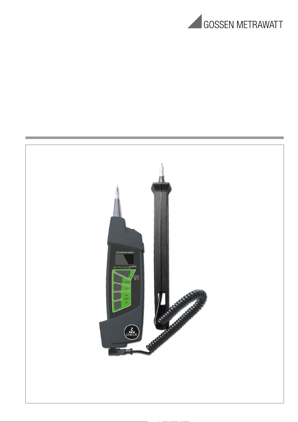
METRALINE Z
CHECK
Loop Resistance Measuring Instrument
3-349-697-03
2/4.13
Page 2

Table of Contents Page
!
Meanings of Symbols on the Instrument
1 Introduction ...................................................................... 2
1.1 Scope of Delivery ...........................................................................2
1.2 Optional accessories ......................................................................2
1.3 Safety Precautions .........................................................................2
1.4 General Device Description .............................................................3
1.5 Applicable Standards .....................................................................3
2 Device Description ........................................................... 3
2.1 Housing ........................................................................................3
2.2 Control Panel .................................................................................3
2.3 Initial Start-Up ...............................................................................4
3 Performing Measurements .............................................. 4
3.1 Switching the Instrument On and Off, Energy-Saving Mode,
Automatic Shutdown ......................................................................4
3.2 Instructions and Principles with Validity for All Measurements ...........4
3.3 Measurement of Fault Loop Impedance and Line Impedance ............5
3.3.1 Measurement in Circuits without RCD – ~ Function .........................5
3.3.2 Displaying Further Measured/Calculated Values ...............................5
3.3.3 Measurement in Electrical Circuits with RCD ...................................5
3.4 Automatic Evaluation of Measured Impedance .................................6
3.5 Further Device Functions ................................................................6
3.6 Device Reset Function ....................................................................6
4 Technical Data ................................................................. 7
4.1 Individual Device Functions ............................................................7
4.2 General Data .................................................................................7
5 Table of Protective Devices Stored to the Instrument ..... 8
6 Maintenance .................................................................... 9
6.1 Device Power Supply .....................................................................9
6.1.1 Inserting and Replacing the Batteries ..............................................9
6.1.2 Recharging the Batteries ................................................................9
6.1.3 Replacing the Fuse ........................................................................9
6.2 Cleaning .......................................................................................9
6.3 Recalibration .................................................................................9
7 Repair and Replacement Parts Service
Calibration Center and Rental Instrument Service ......... 10
8 Product Support ............................................................. 10
1 Introduction
1.1 Scope of Delivery
1 Test instrument with mobile test probe
4 Batteries (AAA)
1Pouch
1 Condensed operating instructions
1
CD ROM with operating instructions in available languages
1 Factory calibration certificate
1.2 Optional accessories
4 ea. rechargeable AAA NIMH batteries (Z507B)
1 battery charger (Z507A)
1.3 Safety Precautions
Read the operating instructions thoroughly and carefully before
using your instrument. Follow all instructions contained therein.
Make sure that the operating instructions are available to all users
of the instrument.
This device is equipped with double
or reinforced insulation.
Danger of injury due to electrical current,
warning regarding dangerous electrical voltage
Warning concerning a source of danger
(attention, observe documentation!)
EC mark of conformity:
This instrument fulfills all requirements of applicable
European directives.
Before using the instrument, it must be assured that it is safe.
Do not use if:
• Visible damage is apparent
• The battery compartment lid is missing
• The device has been stored under unfavorable conditions for
a lengthy period of time
• The device has been handled impermissibly, e.g. has been
dropped from a height of 1 meter or more
• The test instrument does not function as described in these
operating instructions (if this is the case, we recommend
resetting the device as described in section 3.6 on page 7).
CAUTION
• Do not touch electrically conductive parts, test probes etc.
when the device is switched on and voltage might still be conducted by a test probe – DANGER OF INJURY!
• Only use test probes which are included with the instrument
or are available as accessories.
• The device must be switched off and no voltage may be
applied when exchanging accessories.
• It is absolutely essential to adhere to all safety precautions,
regulations and standards when performing measurements.
• No keys may be pressed when connecting the instrument to a
device under test.
• The test instrument may not be subjected to the influence of
aggressive substances, gases, vapors, liquids or dust.
• The test instrument may only be used under the conditions
listed in the technical data in section 4 on page 8.
• If the device is moved from a colder to a warmer room, condensation may occur, in which case a brief period of acclimatization is advisable.
• We recommend removing the batteries during lengthy periods
of storage.
• Testing without tripping of RCCB: During measurement, the
RCCB may be tripped unintentionally. This may be attributable
to a high degree of sensitivity towards short current peaks,
especially with those variants with IΔN = 10 mA and 30 mA,
or the RCCB may be defective or a certain leakage current
may flow through the measured electrical circuit which, in
addition to the current that is produced by the test instrument,
trips the RCCB.
• Two relatively strong magnets are integrated into the test
instrument. Avoid close proximity to magnetically sensitive
objects such as watches, credit cards and the like.
• The illustrations in these operating instructions are drawings
and may therefore deviate from reality.
2 GMC-I Messtechnik GmbH
Page 3
Exclusion of Liability
!
Fixed Test Probe Attached to the Device
LED
OLED Display
Socket for Flexible Test Probe
Socket for Charger
P
l
u
g
-
I
n
M
o
b
i
l
e
T
e
s
t
P
r
o
b
e
Plastic
Control Panel
Housing
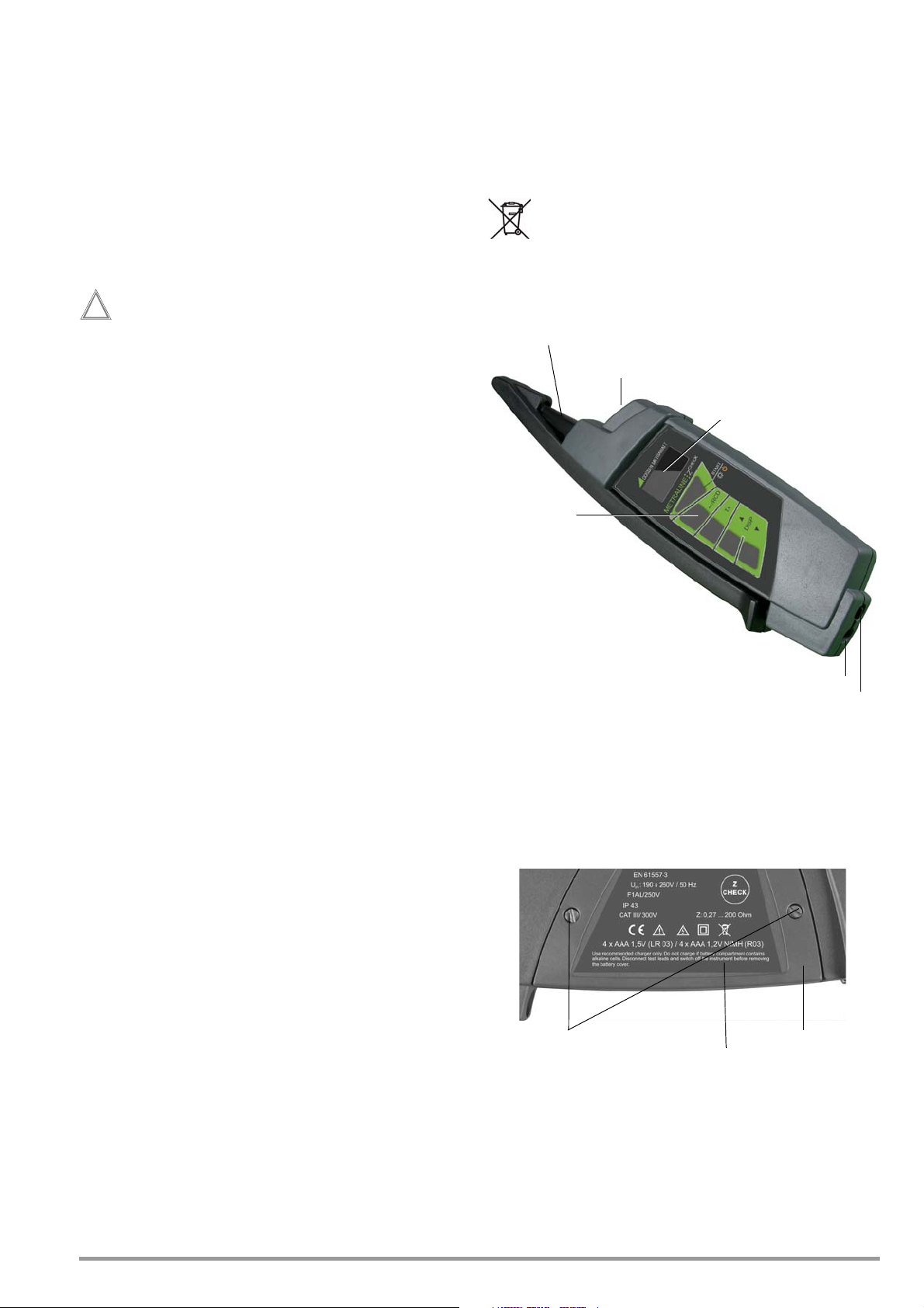
Screws for Battery Compartment Lid
Battery Compartment with Fuse
Battery Compartment Lid
Serial Plate
When testing systems with RCCBs, the latter may switch off. This
may occur even though the test does not normally provide for it.
Leakage currents may be present which, in combination with the
test current of the test instrument, exceed the shutdown threshold value of the RCCB. PCs which are operated in proximity to
such RCCB systems may switch off as a consequence. This may
result in inadvertent loss of data. Before conducting the test, precautions should therefore be taken to ensure that all data and
programs are adequately saved and the computer should be
switched off if necessary. The manufacturer of the test instrument
assumes no liability for any direct or indirect damage to equipment, computers, peripheral equipment or data bases when performing the tests.
1.5 Applicable Standards
Measurement EMC Safety
EN 61557-1 EN 55022 class B EN 61010-1
EN 61557-3 EN 61326-1 EN61010-031
1.6 Environment
The shipping package is made of recyclable cardboard. Batteries
must be disposed of in accordance with applicable regulations.
This device may not be disposed of with the trash. Further information regarding the WEEE mark can be accessed on the Internet at www.gossenmetrawatt.com by entering the search term
“WEEE”.
2 Device Description
• Use original accessories only.
• Max. permissible voltage between test probe and ground is
300 V!
• Maximum permissible voltage between the test probes is
300 V!
Opening of Equipment / Repair
The equipment may be opened only by authorized service personnel to ensure the safe and correct operation of the equipment
and to keep the warranty valid.
Even original spare parts may be installed only by authorized service personnel.
In case the equipment was opened by unauthorized personnel,
no warranty regarding personal safety, measurement accuracy,
conformity with applicable safety measures or any consequential
damage is granted by the manufacturer.
1.4 General Device Description
The test instrument is enclosed in a compact housing with a patented means of retaining the test probes.
The high-contrast, four-color OLED display assures excellent legibility. When performing measurements under unfavorable light
conditions, measuring point illumination can be switched on –
white LED at the front.
The following measurements can be performed with the Metraline
check
Z
:
• Fault loop impedance with short-circuit current
• Fault loop impedance with short-circuit current without tripping the RCCB for measurements of RCCBs with a nominal
current of 100 mA or 300 mA
• Line impedance with short-circuit current
• Line voltage
• Phase detection
check
The Metraline Z
ance in consideration of type, nominal current and disconnection
time. A table with the parameters of various protective devices is
included in device memory (see section 5 on page 9 in these
operating instructions.
allows for the evaluation of measured imped-
2.1 Housing
Figure 2.1: Top View
For transport purposes, the movable test probe can be attached
to the housing and retained by a magnet such that both metal tips
are simultaneously recessed and protected.
In order to charge batteries which have been inserted into the
instrument, the flexible test probe’s connector plug must be
removed and the slide must be pushed to the left, so that the
socket at the right is made accessible and the charger can be
plugged into it.
GMC-I Messtechnik GmbH 3
Figure 2.2: Detail View of the Back Panel with Battery Compartment Lid
Page 4
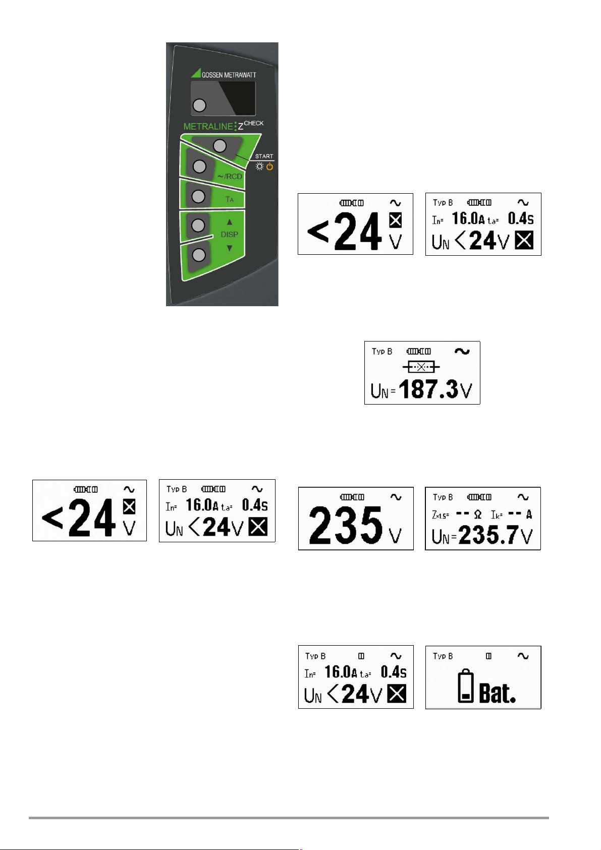
2.2 Control Panel
3
1
2
4
5
5
1 Graphic OLED Display
2 START key:
– Switch on:
Press and hold until the
display lights up.
– Start measurement:
Press and hold until measurement starts.
– Measurement point illumina-
tion:
Press briefly to switch illumination on and off.
– Switch off:
Press twice briefly to switch
the instrument off.
3 ~ / RCD key
Measuring function selection:
with/without RCCB
4The T
5 DISP ▲ and
Figure 2.3: Control Panel and OLED Display
key is used to select
A
the value from the table of
protective devices, which is
used to adjust disconnection
time for evaluating measured
values.
▼ keys for selecting the
DISP
protective device for the evaluation of measured values
pressed and no voltage has been applied to the test probes during this time.
3.2 Instructions and Principles with Validity for All Measurements
• The desired functions and parameters are selected with the
~/RCD, T
by pressing the START key. All selected functions or parameters remain valid until they are changed.
• If a voltage of < 24 V or > 260 V is applied to the test probes,
corresponding information appears at the display and measurement cannot be triggered by pressing the START key.
• If a voltage within a range of 24 V to 190 V is applied to the test
probes, the START key is disabled and “< 190 V” is displayed.
Figure 3.1:Voltage < 24 V
• If the test instrument displays voltage applied to the test
probes after the START key has been pressed, although no
measurement ensues and the blown fuse symbol appears at
the display, the fuse must be replaced.
, DISP ▲ and DISP ▼ keys. Measurement is triggered
A
Figure 3.2: Voltage < 24 V
(brief representation)
(detailed representation)
Data can be represented at the OLED display in two different
ways:
• Brief representation: Measured quantities appear at the display
with large numbers, but no evaluation of the measurement
data is included.
• Detailed representation: Measured quantities appear at the display along with information from the protective devices database, as well as the symbol for “corresponds / does not correspond with the measured impedance”.
Phase and battery level are displayed in both modes.
Refer to the description in section 3.5 on page 7
Figure 2.4: Example of Brief
Representation
Figure 2.5: Example of Detailed
Representation
The information which appears at the display varies depending on
the selected function.
2.3 Initial Start-Up
After inserting the batteries in accordance with section 6.1 on
page 10, the measuring instrument is ready for operation.
3 Performing Measurements
Figure 3.3: Blown Fuse Example
(detailed representation)
• If voltage within a range of 190 V to 260 V is applied to the
test probes, the momentary measured value appears at the
display and measurement can be triggered by pressing the
START key.
Figure 3.4: Voltage Measurement
(brief representation)
Figure 3.5: Voltage Measurement
(detailed representation)
• If battery voltage is too low (only the red field is lit up in the
battery symbol), measurement cannot be started. After pressing the START key, the depleted battery symbol appears for
about 1 second (see figure below). Replace the batteries as
described in section 6.1 on page 10.
3.1 Switching the Instrument On and Off, Energy-Saving Mode, Automatic Shutdown
The instrument is switched on by pressing and holding the START
key. Briefly press the START key twice in order to switch the instru-
ment off, during which no voltage may be applied to the test
probes! The instrument is switched to the standby mode after
several seconds (reduced brightness), if none of the keys has
been pressed and no voltage is applied to the test probes. The
instrument is switched out of the standby mode (i.e. back to full
brightness) by pressing any key or applying voltage to the test
probes. The instrument is shutdown automatically if it has
remained inactive for about 1 minute, i.e. if no keys have been
4 GMC-I Messtechnik GmbH
Figure 3.6: Low Battery Voltage
(detailed representation)
Figure 3.7: Display After Pressing START
(detailed representation)
• If several impedance measurements are performed one after
the other, internal warming of the instrument is displayed by
means of the red indicator – “T” symbol. As temperature
increases, the field is gradually filled in and becomes wider.
Page 5

3.3 Measurement of Fault Loop Impedance and Line Impedance
Figure 3.8: High Temperature Display
(brief representation)
Figure 3.9: High Temperature Display
(detailed representation)
When the maximum permissible internal temperature has been
exceeded, the “T” symbol is replaced with the “STOP” symbol. If
the START key is pressed and held for approximately 1 second,
overheating is displayed and any further measurements are disabled. Allow the instrument to cool down!
Figure 3.10: Overheating Display – STOP
Symbol
Figure 3.11: Overheating Display After
Pressing the Start Key
➭ Securely contact the device under test with the test probes.
Afterwards, check to see whether or not the displayed line
voltage value is stable. Always assure good contact during
measurement in order to prevent distortion of the measurement results.
• The test instrument evaluates deviation while measurement is
being performed. If considerable interference occurs within
the measured system during measurement which would lead
to inaccurate impedance measurement results, impedance
does not appear at the display and the instrument is switched
to voltage measurement after measurement has been completed. The measurement must be repeated!
• If line voltage is unstable while measurement is being performed, or if other electrical circuits parallel to the measured
circuit are in use, measurement results may be distorted and
permissible measuring error may be exceeded.
3.3.1 Measurement in Circuits without RCD –
~ Function
The “~” function is suitable for measuring fault loop impedance in
electrical circuits without RCCBs, as well as line impedance.
➭ After switching the instrument on, connect it between L and
PE in order to measure fault loop impedance, and between L
and N to measure line impedance.
Figure 3.12: Connection Example: Loop Impedance Measurement, L2–PE
➭ After the voltage value has settled in, briefly press the START
key in order to trigger measurement. Assure good contact between the test probes and the device under test while measurement is being performed!
Results after completion of the measurement:
Figure 3.13: Sample Results for Imped-
ance Measurement (brief
representation)
Figure 3.14: Sample Results for Imped-
ance Measurement
(detailed representation)
Key:
Z Measured impedance ()
Z x 1.5 Multiplier for measured impedance Z ()
IK Short-circuit current calculated as: ISC = 230 / (Z x 1.5) (A)
➭ Remove the instrument.
GMC-I Messtechnik GmbH 5
Page 6

3.3.2 Displaying Further Measured/Calculated Values
Attention!
!
Stated briefly: The following are displayed, one after the other, by
pressing the DISP
– Short-circuit current
– 1.5 times measured impedance
– Impedance corrected by a value equal to measuring error
– Measured impedance
▲ and DISP ▼ keys:
3.3.3 Measurement in Electrical Circuits with RCD
Testing Without Tripping the RCCB
Select the “RCD” function if loop impedance needs to be measured via an RCCB, without causing it to trip.
➭ After switching the instrument on, connect it between L and N
in order to measure line impedance.
➭ After the voltage value has settled in, briefly press the ~/RCD
key, which starts measurement of line impedance without tripping the RCD. This is important if loop impedance needs to be
measured via an RCCB.
➭ Assure good contact between the test probes and the device
under test while measurement is being performed!
Figure 3.15: Short-Circuit Current Figure 3.16: 1.5 Times Impedance
Figure 3.17: Impedance + Measuring
Error
Figure 3.18: Measured Impedance
In detail: Impedance corrected by a value equal to measuring error
is displayed by pressing the DISP
value without correction is displayed by pressing the DISP
Figure 3.19: Measured Impedance +
Measuring Error
▲ key, and only the measured
▼ key.
Figure 3.20: Measured Impedance
This function is only possible for RCCB‘s (RCD‘s) with
IΔN ≥ 100 mA. It cannot be guaranteed for 10 mA and
30 mA, see also Safety Precautions in chapter 1.3.
The results appear at the display, and the “~” symbol is replaced
with the “RCD” symbol at the same time.
Testing With Tripping of the RCCB
➭ Connect the test probe from N to PE (see example in figure
3.12).
➭ Start the measurement by pressing the START key. Assure
good contact between the test probes and the device under
test while measurement is being performed!
After the measurement has been completed, the results are displayed as follows:
Figure 3.21: Impedance Downstream
from an RCCB (brief)
Key:
Z Measured impedance ()
Z x 1.5 Multiplier for measured impedance Z ()
K Short-circuit current calculated as: IK = 230 / (Z x 1.5) (A)
I
Figure 3.22: Impedance Downstream
from an RCCB (detailed)
➭ Several seconds after the measurement cables have been re-
moved from the device under test, the test instrument is
switched back to the “~” function. In order to perform further
loop impedance measurements, the entire procedure in accordance with section 3.3.3 on page 6 must be repeated.
➭ In order to display additional measured/calculated values, pro-
ceed as described in section 3.3.2 on page 6, “Displaying Further Measured/Calculated Values”.
Note: Contact PE with the mobile test probe. Press the START key. If
no voltage is present, loop impedance measurement is not
started. Assure that the test probes make good contact with L
and PE.
Make certain that:
– L and PE are contacted
– PE is securely connected
6 GMC-I Messtechnik GmbH
Page 7

3.4 Automatic Evaluation of Measured Impedance
Note
Automatic evaluation is only possible with the detailed representation.
• Protective device parameters are stored to memory or to the
database. Type, nominal current In and disconnection time ta
appear at the top of the display (see example in figure 2.5).
After pressing the T
ta and the smallest short-circuit current IFmin required for
shutdown appear at the bottom of the display.
key for the first time, disconnection time
A
3.5 Further Device Functions
Phase Detection
If the symbol appears in the lower right-hand corner of the
display (see figures 2.4 and 2.5), and if a phase is contacted with
the fixed test probe, the symbol is changed to .
The other test probe may not be connected anywhere or make
any contact at all!
Figure 3.23: Display of Smallest Short-Circuit Current
for Shutting Down a B16 Breaker
• Another protective device type and nominal current can be
selected immediately after activating the TA key by pressing
and holding the DISP
▲ or DISP ▼ key. After selection, wait
about 5 seconds, after which the initial status for voltage measurement is displayed.
• Another disconnection time can be selected immediately after
activating the TA key by pressing the TA key once again. After
selection, wait about 5 seconds, after which the initial status
for voltage measurement is displayed.
• If the symbol is displayed along with the results of the
impedance measurement after its completion, short-circuit
current calculated from impedance is greater than the minimum short-circuit current required for triggering the selected
protective device.
However, if calculated short-circuit current is less than this
value, the symbol is displayed.
Figure 3.24: Phase Display (brief) Figure 3.25: Phase Display (detailed)
As usual, the test instrument must be gripped in the
hand!
In order to obtain a correct display, the fixed test probe
must remain connected to the phase for at least 2 seconds.
Phase voltage to ground must be 190 V / 48 to 52 Hz,
because the display will otherwise be incorrect.
Measuring Point Illumination with White LED
The LED can be switched on and off by briefly pressing the START
key.
No voltage may be applied to the test probes.
Selecting Brief or Detailed Representation, Information on Firmware Version
➭ Press the START key to switch the instrument on while pressing
and holding the ~/RCD key. The version number appears at
the display, for example V 1.0.0, along with corresponding
symbols for the desired representation.
Figure 3.26: Selecting Brief or Detailed Rep-
resentation, Firmware Version
➭ Select the representation mode with the DISP ▲ (brief) or DISP
▼ (detailed) key. After selection, the instrument is switched
back to normal operation.
3.6 Device Reset Function
If the test instrument does not function as described in these
instructions, we recommend a device reset. The test instrument
must be switched off and neither of the test probes may be connected to a DUT. If device functions are still incorrect after switching the instrument back on again, remove the batteries as
described in section 6.1 on page 10, wait at least 10 seconds
and then reinsert the batteries (or replace them with new ones).
If the test instrument still does not function as described, remove
the batteries and contact our service department.
GMC-I Messtechnik GmbH 7
Page 8

4 Technical Data
4.1 Individual Device Functions
Fault Loop Impedance / Line Impedance
Nominal Range per EN 61557-3: 0.27 to 200
Range Resolution Intrinsic Uncertainty Measuring
0.00 to 4.99 0.01 (3% rdg. + 5 D) (4% rdg. + 7 D)
5.0 to 49.9 0.1 (3% rdg. + 3 D) (4% rdg. + 4 D)
50 to 200 1 3% rdg. 4% rdg.
Voltage range: 190 to 260 V / 48 to 52 Hz
Load resistance:50 (variable number of pulses at 10 ms)
Fault Loop Impedance Without Tripping the RCCB
Nominal Range per EN 61557-3: 0.8 to 200
Range Resolution Intrinsic Uncertainty Measuring
0.0 to 4.9 0.1 (5% rdg. + 2 D) (6% rdg. + 2 D)
50 to 200 1 7% rdg. 8% rdg.
Voltage range: 190 to 260 V / 48 to 52 Hz
Load resistance:50 (variable number of pulses and pulse width)
Short-Circuit Current
Range Resolution Intrinsic Uncertainty Measuring
0 to 999 A 1 A
1.0 to 9.9 kA 0.1 kA
10 to 23 kA 1 kA
Depending on
measuring error
for loop impedance 1 D
Alternating Voltage (TRMS)
Range Resolution Intrinsic Uncertainty Measuring
24 to 260 V 1 V
0.1 V
1
(2% rdg. + 2 D) (3% rdg. + 3 D)
2
Frequency range: 48 to 52 Hz
1
Display for brief representation
2
Display for detailed representation
Key:
a) The measuring uncertainties specified here for fault loop impedance, line imped-
ance and short-circuit current are only valid if line voltage is stable during measurement and if no other electrical circuits parallel to the measured circuit are in use.
c) rdg. means reading, i.e. measured value, D = digits (i.e. number of the decimal
place with the least significance)
Uncertainty
Uncertainty
Uncertainty
Depending on
measuring error
for loop impedance 1 D
Uncertainty
4.2 General Data
Reference Conditions
Temperature 23 ± 2° C
Relative humidity 40 to 60%
Line voltage 230 V
2% / 50 Hz 1%
Device position any
Ambient Conditions
Operating Conditions
Operating temperature
0 to 40° C
Relative Humidity max. 85 %, no condensation allowed
Line voltage 190 to 260 V / 48 to 52 Hz
Device position any
Storage Conditions
Temperature -10 to 70° C
Relative Humidity max. 90% at -10 to +40° C
max. 80% at +40 to +70° C
Device position any
Power Supply
Batteries 4 ea. AAA (LR03), 1.5 V alkaline or
Number of
measurements with batteries at 800 mAh:
1.2 V NIMH (with at least 750 mAh)
approx. 3,000 measurements
Electrical Safety
Measuring category with safety cap applied to measuring
probe: CAT III 300 V
without safety cap applied to measuring
probe: CAT I I 300 V
Pollution degree 2
Protection class II
Fuse SIBA ceramic fuse
6.3 mm x 32 mm, F1 A/600 V
switching capacity 50 kA at 600 V
Mechanical Design
Display OLED, multicolored, graphic
Protection IP 43
Dimensions approx. 260 x 70 x 40 mm
Weight approx. 0.36 kg with batteries
8 GMC-I Messtechnik GmbH
Page 9

5 Table of Protective Devices Stored to the
Instrument
Fuse Type NV
Nominal
Current
(A)
2 32.5 22.3 18.7 15.9 9.1
4 65.6 46.4 38.8 31.9 18.7
6 102.8 70 56.5 46.4 26.7
10 165.8 115.3 96.5 80.7 46.4
16 206.9 150.8 126.1 107.4 66.3
20 276.8 204.2 170.8 145.5 86.7
25 361.3 257.5 215.4 180.2 109.3
35 618.1 453.2 374 308.7 169.5
50 919.2 640 545 464.2 266.9
63 1217.2 821.7 663.3 545 319.1
80 1567.2 1133.1 964.9 836.5 447.9
100 2075.3 1429 1195.4 1018 585.4
125 2826.3 2006 1708.3 1454.8 765.1
160 3538.2 2485.1 2042.1 1678.1 947.9
200 4555.5 3488.5 2970.8 2529.9 1354.5
250 6032.4 4399.6 3615.3 2918.2 1590.6
315 7766.8 6066.6 4985.1 4096.4 2272.9
400 10577.7 7929.1 6632.9 5450.5 2766.1
500 13619 10933.5 8825.4 7515.7 3952.7
630 19619.3 14037.4 11534.9 9310.9 4985.1
710 19712.3 17766.9 14341.3 11996.9 6423.2
800 25260.3 20059.8 16192.1 13545.1 7252.1
1000 34402.1 23555.5 19356.3 16192.1 9146.2
1250 45555.1 36152.6 29182.1 24411.6 13070.1
35m 0.1 02 0.4 5
Fuse Type gG
Nominal
Current
(A)
2 32.5 22.3 18.7 15.9 9.1
4 65.6 46.4 38.8 31.9 18.7
6 102.8 70 56.5 46.4 26.7
10 165.8 115.3 96.5 80.7 46.4
13 193.1 144.8 117.9 100 56.2
16 206.9 150.8 126.1 107.4 66.3
20 276.8 204.2 170.8 145.5 86.7
25 361.3 257.5 215.4 180.2 109.3
32 539.1 361.5 307.9 271.7 159.1
35 618.1 453.2 374 308.7 169.5
40 694.2 464.2 381.4 319.1 190.1
35m 0.1 02 0.4 5
Fuse Type B
Nominal
Current
(A)
63030303030
10 50 50 50 50 50
13 65 65 65 65 65
16 80 80 80 80 80
20 100 100 100 100 100
25 125 125 125 125 125
32 160 160 160 160 160
40 200 200 200 200 200
50 250 250 250 250 250
63 315 315 315 315 315
35m 0.1 02 0.4 5
Disconnecting Time [s]
Min. Short-Circuit Current (A)
Disconnecting Time [s]
Min. Short-Circuit Current (A)
Disconnecting Time [s]
Min. Short-Circuit Current (A)
Fuse Type C
Nominal
Current
(A)
05 5 5 5 5 2.7
1101010105.4
1.6161616168.6
22020202010.8
44040404021.6
66060606032.4
10 100 100 100 100 54
13 130 130 130 130 70.2
16 160 160 160 160 86.4
20 200 200 200 200 108
25 250 250 250 250 135
32 320 320 320 320 172.8
40 400 400 400 400 216
50 500 500 500 500 270
63 630 630 630 630 340.2
Fuse Type K
Nominal
Current
(A)
05 7.5 7.5 7.5 7.5
115151515
1.624242424
230303030
460606060
690909090
10 150 150 150 150
13 195 195 195 195
16 240 240 240 240
20 300 300 300 300
25 375 375 375 375
32 480 480 480 480
Fuse Type D
Nominal
Current
(A)
05 10 10 10 10 2.7
1202020205.4
1.6323232328.6
24040404010.8
48080808021.6
6 120 120 120 120 32.4
10 200 200 200 200 54
13 260 260 260 260 70.2
16 320 320 320 320 86.4
20 400 400 400 400 108
25 500 500 500 500 135
32 640 640 640 640 172.8
Disconnecting Time [s]
35m 0.1 02 0.4 5
Min. Short-Circuit Current (A)
Disconnecting Time [s]
35m 0.1 02 0.4
Min. Short-Circuit Current (A)
Disconnecting Time [s]
35m 0.1 02 0.4 5
Min. Short-Circuit Current (A)
GMC-I Messtechnik GmbH 9
Page 10

6 Maintenance
Caution: Dangerous Voltage!
Note
Attention!
!
Attention!
!
Attention!
!
6.1 Device Power Supply
Dangerous voltage in battery compartment!
Disconnect the test probes from the device under test and
switch the instrument off before removing the battery compartment lid.
The instrument may not be placed into service if the battery
compartment lid has not been inserted and secured with
the screws.
Either alkaline batteries or rechargeable NiCD/NiMH batteries may
be used to supply the instrument with electrical power (4 each,
size: AAA, type: LR03).
The battery charge level is continuously displayed (see section 3.2
on page 4).
If too little voltage is indicated, replace the batteries.
We recommend removing the batteries during lengthy
periods of non-use (e.g. vacation). This prevents excessive battery depletion or leakage, which may result in
damage to the instrument under unfavorable conditions.
6.1.1 Inserting and Replacing the Batteries
Loosen the two screws at the back of the instrument and remove
the battery compartment lid. Insert the batteries assuring correct
polarity!
Safety Precautions
• Do not attempt to recharge alkaline batteries: they may leak,
explode etc. The test instrument may be severely damaged or
destroyed as a result.
• After initially charging new batteries and after rechargeable
batteries have not been used for a lengthy period of time (several months), operating hours after charging may be significantly less than usual. If this is the case, repeat the charging
procedure several times.
Autonomous, intelligent charging stations execute charging/
discharging cycles of this sort automatically (see instructions
included with the charging station). This procedure increases
the capacity of the batteries, thus making longer periods of
operation possible between charging cycles.
• If no improvement is achieved in this way, one or more of the
rechargeable batteries may no longer fulfill the original specifications. If this is the case, the defective rechargeable battery
should be identified, e.g. with the help of the voltage measurement, and replaced.
• Battery capacity is gradually reduced as a result of long and
frequent use. When you notice that this is the case, all of the
rechargeable batteries should be replaced.
6.1.3 Replacing the Fuse
The fuse may only be replaced with the fuse type specified in section “Technical Data” . If any other fuse is inserted, this may result in damage to the instrument and/
or danger for the user!
Figure 6.1: Correct Battery Polarity
Always replace all 4 batteries at once, and use high quality batteries. Replace the battery compartment lid and retighten the
screws.
6.1.2 Recharging the Batteries
Use only the charger (Z507A) which is offered as an optional accessory for this instrument to charge the batter-
ies inserted in the instrument.
Make sure that the following conditions have been fulfilled before connecting the charger to the charging socket:
– rechargeable batteries have been inserted with correct
polarity, no normal batteries
– The test instrument has been disconnected from the
measuring circuit at all poles
– The instrument must remain off during charging.
6.2 Cleaning
Use a soft cloth and soapy water for cleaning. Do not place the
test instrument back into service until its surface is completely dry.
Do not use cleaning agents which contain benzine or alcohol! Prevent liquids from penetrating into the test instrument’s interior.
Recharging of the batteries begins as soon as the charger is connected to the mains and to the charging socket (see figure 6.1).
Charging takes 5 hours and 30 minutes (integrated safety timer) if
the batteries have been fully depleted.
10 GMC-I Messtechnik GmbH
Page 11

6.3 Recalibration
The measuring tasks performed with your instrument, and the
stressing it’s subjected to, influence aging of its components and
may result in deviation from the specified levels of accuracy.
7 Repair and Replacement Parts Service
Calibration Center and Rental Instrument Service
If required please contact:
In the case of strict measuring accuracy requirements, as well as
in the event of use at construction sites with frequent stress due
to transport and considerable temperature fluctuation, we recommend a relatively short calibration interval of once per year. If your
instrument is used primarily in the laboratory and indoors without
considerable climatic or mechanical stressing, a calibration interval of once every 2 to 3 years is sufficient as a rule.
During recalibration* at an accredited calibration laboratory
(DIN EN ISO/IEC 17025), deviations from traceable standards
demonstrated by your measuring instrument are documented.
Ascertained deviations are used to correct displayed values during later use of the instrument.
We would be happy to perform DAkkS or factory calibration for
you at our calibration laboratory. Further information is available at
our website:
www.gossenmetrawatt.com ( Company DAkkS Calibration
Center or FAQs General – Calibration Questions and
Answers ).
Recalibration of your instrument at regular intervals is essential for
the fulfillment of requirements according to quality management
systems per DIN EN ISO 9001.
GMC-I Service GmbH
Service Center
Thomas-Mann-Str. 20
90471 Nürnberg, Germany
Phone: +49 911 817718-0
Fax: +49 911 817718-253
E-mail service@gossenmetrawatt.com
www.gmci-service.com
This address is only valid in Germany. Please contact our representatives or subsidiaries for service in other countries.
8 Product Support
If required please contact:
GMC-I Messtechnik GmbH
Product Support Hotline
Phone: +49-911-8602-0
Fax: +49 911 8602-709
E-mail: support@gossenmetrawatt.com
*
Examination of the specification, as well as adjustment, are not included in calibration. However, in the case of our own products, any required adjustment is performed and adherence to the specification is confirmed.
Edited in Germany • Subject to ch ange without notice • PDF version available on the Internet
GMC-I Messtechnik GmbH
Südwestpark 15
90449 Nürnberg •
Germany
Phone: +49 911 8602-111
Fax: +49 911 8602-777
E-mail: info@gossenmetrawatt.com
www.gossenmetrawatt.com
 Loading...