

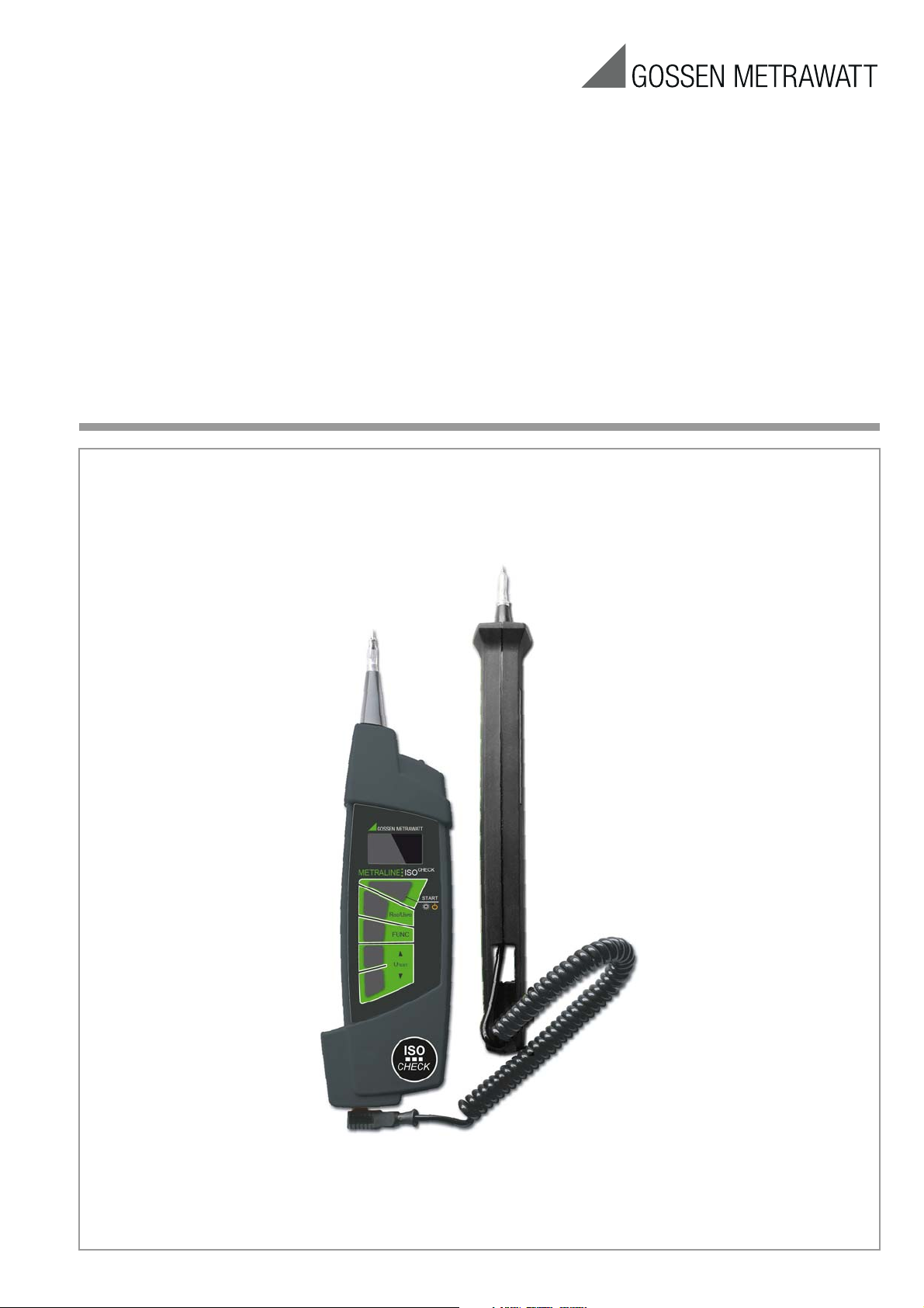
Operating Instructions
METRALINE ISO
CHECK
Insulation Resistance Tester
3-349-691-03
2/4.13
Table of Contents
!
!
Page
1 Introduction ...................................................................... 2
1.1 Scope of Delivery ...........................................................................2
1.2 Optional Accessories ......................................................................2
1.3 Safety Precautions .........................................................................2
1.4 Applications ..................................................................................3
1.5 Applicable Standards .....................................................................3
1.6 Environment ..................................................................................3
2 Device Description ........................................................... 3
2.1 Housing ........................................................................................3
2.2 Control Panel .................................................................................3
2.3 Initial Start-Up ...............................................................................3
3 Performing Measurements .............................................. 4
3.1 Switching the Instrument On and Off, Energy-Saving Mode,
Automatic Shutdown ......................................................................4
3.2 Instructions and Principles with Validity for
All Measurements ..........................................................................4
3.3 Measuring Functions ......................................................................4
3.3.1 Voltage Measurement ....................................................................4
3.3.2 Insulation Resistance Measurement ................................................5
3.3.3 Measurements at Varistors (surge protection devices) ......................5
3.4 Further Device Functions ................................................................6
3.5 Device Reset Function ....................................................................7
4 Technical Data ................................................................. 7
4.1 Measuring Functions ......................................................................7
4.2 General Data .................................................................................7
5 Maintenance .................................................................... 7
5.1 Device Power Supply .....................................................................7
5.1.1 Inserting and Replacing the Batteries ..............................................7
5.1.2 Recharging the Batteries ................................................................8
5.2 Cleaning .......................................................................................8
5.3 Recalibration .................................................................................8
6 Repair and Replacement Parts Service,
Calibration Center and Rental
Instrument Service ........................................................... 8
7 Product Support ............................................................... 8
1 Introduction
1.1 Scope of Delivery
1 Test instrument with mobile test probe
4 Batteries (AAA)
1Pouch
1 Condensed operating instructions
1
CD ROM with operating instructions in available languages
1 Factory calibration certificate
1.2 Optional Accessories
4 ea. rechargeable AAA NiMH batteries (Z507B)
1 battery charger (Z507A)
1.3 Safety Precautions
Read the operating instructions thoroughly and carefully before
using your instrument. Follow all instructions contained therein.
Make sure that the operating instructions are available to all users
of the instrument.
Meanings of Symbols on the Instrument
This device is equipped with double or reinforced insulation.
Danger of injury due to electrical current,
warning regarding dangerous electrical voltage
Warning concerning a source of danger
(attention, observe documentation!)
EC mark of conformity: This instrument fulfills all
requirements of applicable European directives.
Before using the instrument, it must be assured that it is safe. Do
not use if:
• Visible damage is apparent
• The battery compartment lid is missing
• The device has been stored under unfavorable conditions for
a lengthy period of time
• The device has been handled impermissibly, e.g. has been
dropped from a height of 1 meter or more
• The test instrument does not function as described in these
operating instructions (if this is the case, we recommend
resetting the device as described in section 3.5 on page 7)
CAUTION
• Do not touch electrically conductive parts, test probes etc.
when the device is switched on and voltage might still be conducted by a test probe – DANGER OF INJURY!
• Only use test probes which are included with the instrument
or are available as accessories.
• The device must be switched off and no voltage may be
applied when exchanging accessories.
• It is absolutely essential to adhere to all safety precautions,
regulations and standards when performing measurements.
• No keys may be pressed when connecting the instrument to a
device under test.
• The test instrument may not be subjected to the influence of
aggressive substances, gases, vapors, liquids or dust.
• The test instrument may only be used under the conditions
listed in the technical data in section 5 on page 7.
• If the device is moved from a colder to a warmer room, condensation may occur, in which case a brief period of acclimatization is advisable.
• We recommend removing the batteries during lengths periods
of storage.
• Two relatively strong magnets are integrated into the test
instrument. Avoid close proximity to magnetically sensitive
objects such as watches, credit cards and the like.
• The illustrations in these operating instructions are drawings
and may therefore deviate from reality.
• Use original accessories only.
• Maximum permissible voltage between test probe and ground
is 300 V!
• Maximum permissible (externally applied) voltage between the
test probes is 600 V!
Opening of Equipment / Repair
The equipment may be opened only by authorized service personnel to ensure the safe and correct operation of the equipment
and to keep the warranty valid.
Even original spare parts may be installed only by authorized service personnel.
In case the equipment was opened by unauthorized personnel,
no warranty regarding personal safety, measurement accuracy,
conformity with applicable safety measures or any consequential
damage is granted by the manufacturer.
2 GMC-I Messtechnik GmbH
1.4 Applications
Fixed Test Probe Attached to the Device
LED
OLED Display
Socket for Flexible Test Probe
Socket for Charger
P
l
u
g
-
I
n
M
o
b
i
l
e
T
e
s
t
P
r
o
b
e
Plastic
Control Panel
Housing
Screws for Battery Compartment Lid
Battery Compartment Lid
Serial Plate
3
1
2
4
5
6
The test instrument consists of a compact housing with a patented means of retaining the second test probe.
The high-contrast, four-color OLED display assures excellent legibility. When performing measurements under unfavorable light
conditions, measuring point illumination can be switched on –
white LED at the front.
The test instrument is capable of the following measurements:
– Insulation resistance with test voltages of 50 to 1000 V
– Surge protection devices with test voltages of 50 to 1000 V
– Direct and alternating voltages
1.5 Applicable Standards
Measurement EMC Safety
EN 61557-1 EN 55022 class B EN 61010-1
EN 61557-2 EN 61326-1 EN61010-031
1.6 Environment
The shipping package is made of recyclable cardboard.
Batteries must be disposed of in accordance with applicable
regulations.
This device may not be disposed of with the trash. Further
information regarding the WEEE mark can be accessed
on the Internet at www.gossenmetrawatt.com by entering
the search term “WEEE”.
2 Device Description
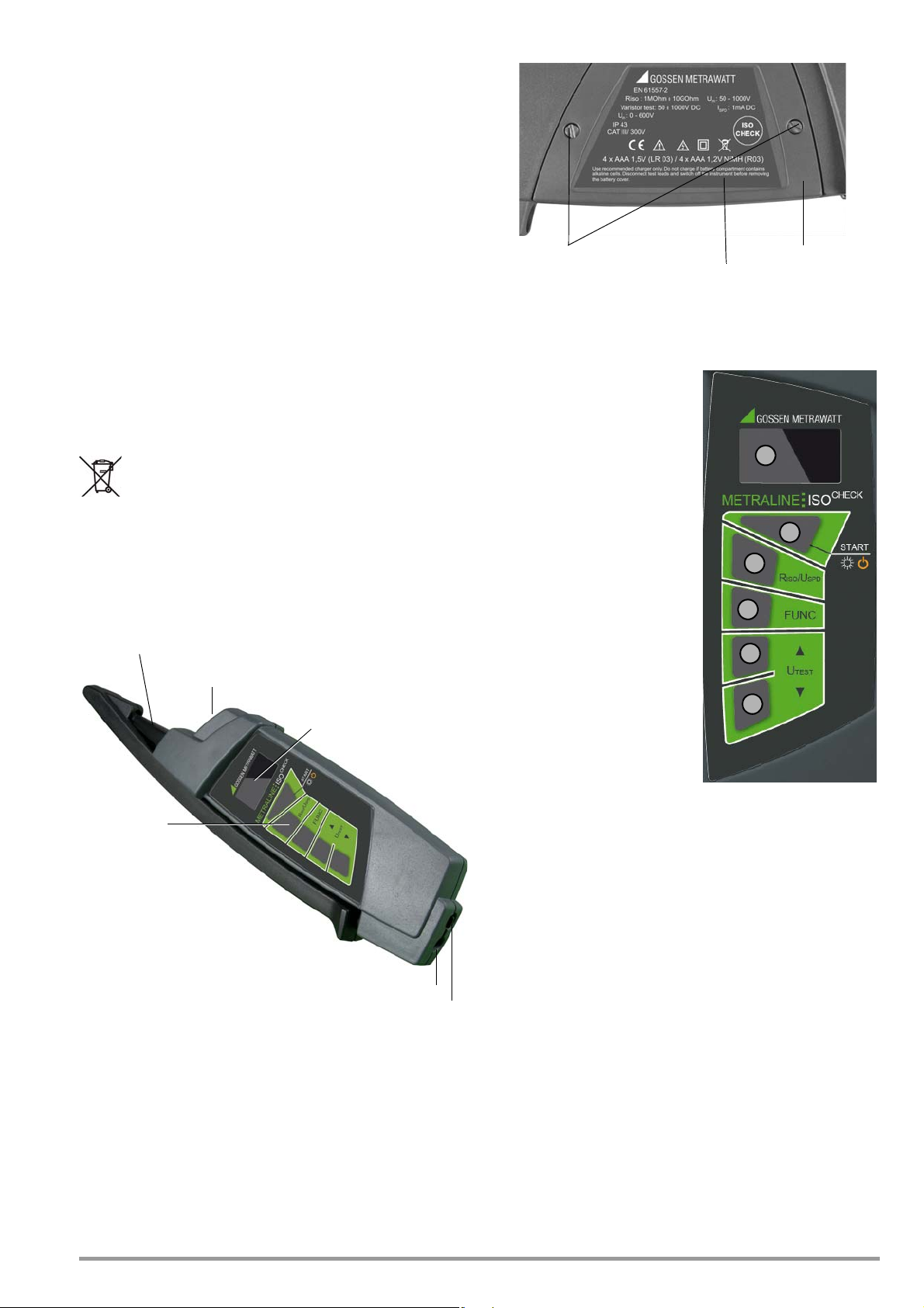
2.1 Housing
Figure 2.2: Detail View of the Back Panel with Battery
Compartment Lid
2.2 Control Panel
1 Graphic OLED display
2 START key:
– Switch on:
Press and hold until the display lights up.
– Start measurement:
Press and hold until measurement starts.
– Measurement point illumina-
tion:
Press briefly to switch illumination on and off.
– Switch off:
Press twice briefly to switch
the instrument off.
3 R
ISO/USPD KEY:
For switching between insulation resistance and surge protection measurement
4The FUNC key allows for selec-
tion of the desired type of
surge protection when USPD
is activated.
5 U
TEST ▲ key for selecting
measuring voltage
TEST ▼ key for selecting
6 U
measuring voltage
Figure 2.1: Top View
For transport purposes, the movable test probe can be attached
to the housing and retained by a magnet such that both metal tips
are simultaneously recessed and protected.
In order to charge batteries which have been inserted into the
instrument, the flexible test probe’s connector plug must be
removed and the slide must be pushed to the left, so that the
socket at the right is made accessible and the charger can be
plugged into it.
GMC-I Messtechnik GmbH 3
Figure 2.3: Control Panel and OLED Display
2.3 Initial Start-Up
After inserting the batteries in accordance with section 5.1 on
page 7, the measuring instrument is ready for operation.

3 Performing Measurements
!
3.3 Measuring Functions
3.1 Switching the Instrument On and Off, Energy-Saving Mode, Automatic Shutdown
The instrument is switched on by pressing and holding the START
key. Briefly press the START key twice in order to switch the instru-
ment off, during which no voltage may be applied to the test
probes! The instrument is switched to the standby mode after
several seconds (reduced brightness), if none of the keys has
been pressed and no voltage is applied to the test probes. The
instrument is switched out of the standby mode (i.e. back to full
brightness) by pressing any key or applying voltage to the test
probes. The instrument is shutdown automatically if it has
remained inactive for about 1 minute, i.e. if no keys have been
pressed and no voltage has been applied to the test probes during this time.
3.2 Instructions and Principles with Validity for All Measurements
• The desired functions or parameters are selected with the
R
ISO/USPD, FUNC, UTEST ▲ and UTEST ▼ keys. Measurement is
triggered by pressing the START key. All selected functions or
parameters remain valid until they are changed.
• If (interference) voltage of greater than 10 V is applied to the
test probes, this is indicated at the display in the UIN field
along with the measured value, as well as the “!” symbol. If
this is the case, the START key is disabled.
Attention!
• Each time before measuring insulation resistance or surge
protection, make sure that the device under test is voltagefree!
• Do not touch the device under test or the test probes during
measurement, and for a short time thereafter as long the DUT
is being discharged.
• The DUT may be charged with as much as 1000 V during
measurement, for which reason contact to the DUT must be
maintained after measurement has been completed until it is
fully discharged! Residual voltage appears at the display along
with the “!” warning symbol.
• Do not remove the test probes until voltage has dropped to a
safe level and the “!” warning symbol has been cleared from
the display.
• All consuming devices must be disconnected and the
switches must be turned on when measuring insulation resistance between conductors.
3.3.1 Voltage Measurement
➭ Connect the test instrument to the device under test.
Bild 3.1 (Interference) Voltage Display
• If battery voltage is too low (only the red field is lit up in the
battery symbol), measurement cannot be started. After pressing the START key, the depleted battery symbol appears for
about 1 second (see figure below). Replace the batteries as
described in section 5.1 on page 7.
Figure 3.2: Low Battery
Voltage
➭ When measuring high insulation resistance, the measurement
cables should be laid unobstructed in the room, or placed
upon a material with good insulating properties.
➭ Contact the device under test with the test probe before trig-
gering measurement with the START key, thus causing any
possible interference voltage to appear at the display.
➭ Do not remove the test probes prematurely during the course
of the measurement, because this may lead to distorted measurement results.
Figure 3.3: Low Battery
Voltage: Display
After Pressing the
START Key
Figure 3.4: Connection Example for Voltage Measurement
• If a voltage of greater than about 10 V is present in the measured electrical circuit, its value is displayed in the U
the “~” symbol appears for AC or polarity is displayed for DC.
The “+” symbol lights up if the positive pole is connected to
the fixed test probe, and “–” appears if the negative pole is
connected to the fixed test probe. “!” appears at the same
time as a warning. The START key is disabled!
IN field and
After insulation measurement has been completed, any remaining
residual voltage is displayed as U
capacitance. Contact to the device under test must be maintained for as long as a capacitive DUT is being discharged via the
test instrument’s internal resistor. The falling voltage value can be
observed directly at the U
until voltage U
4 GMC-I Messtechnik GmbH
IN is less than 25 V!
IN , which may result from cable
IN display. Do not disconnect the DUT
Figure 3.5: Display of (Inter-
ference) Voltage
(Riso function)
Figure 3.6: Voltage
Measurement
SPD function)
(U

3.3.2 Insulation Resistance Measurement
Note
Note
Note
Note
Switch to off position!
USER
USER
USER
USER
➭ Switch insulation measurement on by pressing the RISO/USPD
key.
Figure 3.7: Setting Test Voltage
➭ Select the required measuring voltage with the help of the
▲
UTEST and ▼ UTEST keys. By briefly pressing the respective
key, voltage is increased or decreased to one of the following
nominal values: 50, 100, 250, 500 or 1000 V. The selected
test voltage appears at the display in the U
vidualized value settings, press and hold either the
TEST field. For indi-
▲ UTEST or
▼ UTEST key until the value can be changed in 1 V steps
within a range of 50 to 1000 V. The desired value is then selected by once again briefly pressing the respective key. Several seconds after one of these two keys has been activated
for the last time, the test instrument is returned to the mode
which allows for switching amongst nominal values of 50,
100, 250, 500, 1000 V only.
➭ Contact the device under test with both test probes.
➭ Read the measured insulation resistance value.
The device under test may not be disconnected from the
test instrument as long as the “!” warning symbol is lit up.
Discharging large capacitances may take several tens of
seconds!
Figure 3.9: Sample Results for an
Insulation Measurement (the DUT is
being discharged)
Figure 3.10: Insulation Measure-
ment Results (the DUT
has been fully
discharged: U
IN = 0 V)
Whistling or hissing noises may emanate from the test
instrument during measurement.
3.3.3 Measurements at Varistors (surge protection devices)
For this measuring function, the test instrument generates a rising
direct voltage within a range of 50 to 1000 V and, at the same
time, measures current flowing through the device under test. As
soon as current reaches a level of 1 mA, voltage is no longer
increased and the voltage value for the so-called milliampere
point appears at the display. In accordance with the respective
function which has been selected with the FUNC key, results for
overcurrent protection devices are also evaluated automatically
and listed as shown in the following table.
Note
If the DCMAX function has been selected, the upper voltage
limit for automatic results evaluation can be adjusted with the
▲ UTEST and ▼ UTEST keys.
If the DCMIN function has been selected, the lower voltage
limit for automatic results evaluation can be adjusted with the
▲ UTEST and ▼ UTEST keys.
Figure 3.8: Connection Example
If an interference voltage of greater than about 10 V is
present in the measured electrical circuit, its value is displayed and the START key is disabled (see section 3.3.1
on page 4). Eliminate the source of interference voltage
before continuing with the measurement.
➭ Trigger measurement by pressing the START key. Release the
key as soon as measurement is started.
Rising measuring voltage is displayed by means of a bar
graph (this may take several tens of seconds in the case of
large capacitances). At the same time, the value appears at
the display in the UIN field. The measuring cycle is ended automatically.
If measurement needs to be continued for a longer period
of time, the START key has to be pressed and held for the
entire duration.
In contrast to this, the automatic cycle can be ended prematurely by briefly pressing the START key. No results are
displayed in this case.
For actual measurement or evaluation, it doesn’t matter which of
these two functions is selected, i.e. either DCMAX or DCMIN.
Symbol in the Display and its Meaning
Selected function
DC Voltage at the milliampere point
DCMAX
DCMIN
SPD LIST * Voltage at the milliampere point
* Table for Surge Protection Device
is measured
Voltage at the milliampere point
is within the specified range
is within the specified range for
the selected type of surge protection device
Voltage at the milliampere point
is outside of the measuring
range
Voltage at the milliampere point
is outside of the specified range
Voltage at the milliampere point
is outside of the specified range
for the selected type of surge
protection device
If the SPD LIST function is selected (SURGE PROTECTION DEVICE
TABLE), a specific type and manufacturer/distributor is suggested
at the display, voltage at the milliampere point is displayed and
further information may appear as well.
The required type of surge protection device can be selected with
the
▲ UTEST and ▼ UTEST keys.
GMC-I Messtechnik GmbH 5

If the symbol is included in the description of the surge pro-
Note
Note
!
tection device, the manufacturer’s instructions must be observed
for the respective device type.
The actual measurement is performed as follows:
➭ Select measurement of surge protection devices with the
ISO/USPD key, and select the desired sub-function with the
R
FUNC key (see also description above). Example:
After insulation measurement has been completed, any remaining
residual voltage is displayed as UIN, which may result from cable
capacitance. Contact to the device under test must be maintained for as long as the capacitive DUT is being discharged via
the test instrument’s internal resistor. The falling voltage value can
be observed directly at the UIN display. Do not disconnect the
DUT until voltage U
IN is less than 25 V!
Figure 3.11: Surge Protection Device Measurement Menu,
DC Function
➭ Connect the test probes to the surge protection device in ac-
cordance with the manufacturer’s instructions.
Figure 3.13: Sample Results
for the USPD
Measurement
(discharging is
active: residual
voltage = 144 V)
Figure 3.14: Further Sample
Results for the
SPD Measure-
U
ment (DUT is fully
discharged: residual voltage = 0 V)
Comments
• Before measuring surge protection devices, disconnect them
from the installation.
• It’s advisable to study the circuit before performing measurement. Surge protection devices are currently equipped with
integrated interference suppression filters and the like, which
may influence measurement results.
3.4 Further Device Functions
Select Language, Query Firmware Version
Before selecting a language or querying the firmware version, disconnect both test probes from the device under test / measuring
circuit and switch the test instrument off.
➭ Press and hold the R
strument on.
The firmware version and other service information appears at the
display, as well as the language selection menu.
➭ Select the desired language with the corresponding key
(EN = English, CZ = Czech).
ISO/USPD key while switching the test in-
Figure 3.12: Connection Example
Figure 3.15: Language Selection Menu
Note
If a voltage of greater than about 10 V is present at the measured
surge protection device, its value is displayed and the START key is
disabled (see section 3.3.1 on page 4). Eliminate the source of
interference voltage before restarting the measurement.
The instrument is switched back to normal operation after a language has been selected.
Measuring Point Illumination with White LED
➭ Trigger measurement by pressing the START key. Release the
START key as soon as measurement is started. Rising current
at the surge protection device is displayed by means of a bar
graph. At the same time, the measuring voltage value appears
at the display in the U
IN field. Measurement is ended automat-
ically.
➭ Read voltage measured at the milliampere point.
The device under test may not be disconnected from the
test instrument as long as the “!” warning symbol is lit up.
6 GMC-I Messtechnik GmbH
The LED can be switched on and off by briefly pressing the START
key.
No voltage may be applied to the test probes.

3.5 Device Reset Function
Caution: Dangerous Voltage!
Note
If the test instrument does not function as described in these
instructions, we recommend a device reset. The test instrument
must be switched off and neither of the test probes may be connected to a DUT. If device functions are still incorrect after switching the instrument back on again, remove the batteries as
described in section 5.1 on page 7, wait at least 10 seconds and
then reinsert the batteries (or replace them with new ones).
If the test instrument still does not function as described, remove
the batteries and contact our service department.
4 Technical Data
4.1 Measuring Functions
Insulation Resistance
Nominal Range per EN 61557-2: 0.100 M – Rmax*
Range Resolution Intrinsic Uncertainty Measuring
0.100 to 9.999 M 0.001 M (2% rdg. + 10 d) (3 % rdg. + 20 d)
10.00 to 99.99 M 0.01 M (2% rdg. + 10 dd) (3% rdg. + 20 d)
100.0 to 999.9 M 0.1 M (2% rdg. + 10 d) (3% rdg. + 20 d)
1.000 G ... Rmax* 0.001 G (4% rdg. + 15 d) (5% rdg. + 25 d)
* The Rmax value depends on the selected test voltage:
Nominal voltage of 50 to 99 V Rmax = 1.999 G
Nominal voltage of 100 to 249 V Rmax = 3.999 G
Nominal voltage of 250 to 1000 V Rmax = 9.999 G
Nom. measuring voltage 50 to 1000 V
Adjustable in steps of 1 V
Measuring voltage -0%/+10% of nominal voltage
Nom. measuring current 1 mA (where Umes > Unom)
Short-circuit current < 3 mA
Automatic discharging
of the DUT Yes
Number of
measurements Approx. 250 (with new alkaline batter-
ies)
Surge Protection
Range Resolution Intrinsic Uncertainty Measuring
40 to 1050 V 1 V (2% rdg. + 2 d) (3% rdg. + 3 d)
Measuring method Rising DC voltage when measuring the so-
called milliampere point
Direct and Alternating Voltage (frequency range: 45 to 65 Hz)
Range Resolution Intrinsic Uncertainty Measuring
0 to 600 V 1 V (2% rdg. + 2 d) (3% rdg. + 3 d)
Key
a) The TRMS value for alternating voltage is measured.
b) rdg. means reading, i.e. measured value.
d = digits (i.e. number of the decimal place with the least significance)
4.2 General Data
Reference Conditions
Temperature 23 ± 2° C
Relative humidity 40 to 60%
Device position Any
Uncertainty
Uncertainty
Uncertainty
Ambient Conditions
Operating Conditions
Operating temperature0 to 40° C
Relative humidity Max. 85%, no condensation allowed
Device position Any
Storage Conditions
Temperature -10 to 70° C
Relative humidity Max. 90% at -10 to +40° C
Max. 80% at +40 to +70° C
Device position Any
Power Supply
Batteries 4 ea. AAA (LR03), 1.5 V alkaline or
1.2 V NIMH (with at least 750 mAh)
Number of
measurements with batteries at 800 mAh:
approx. 1,000 measurements
(with 500 V test voltage on 500 k
Electrical Safety
Measuring category with safety cap applied to test probe:
CAT III 300 V
without safety cap applied to test probe:
CAT I I 300 V
Pollution degree 2
Protection class II
Mechanical Design
Display OLED, multicolored, graphic
Protection IP 43
Dimensions Approx. 260 x 70 x 40 mm
Weight Approx. 0.36 kg with batteries
5 Maintenance
5.1 Device Power Supply
Dangerous voltage in battery compartment!
Disconnect the test probes from the device under test and
switch the instrument off before removing the battery compartment lid.
The instrument may not be placed into service if the battery
compartment lid has not been inserted and secured with
the screws.
Either alkaline batteries or rechargeable NiCD/NiMH batteries may
be used to supply the instrument with electrical power (4 each,
size: AAA, type: LR03).
The battery charge level is continuously displayed (see section 3.2
on page 4).
If too little voltage is indicated, replace the batteries.
We recommend removing the batteries during lengthy
periods of non-use (e.g. vacation). This prevents excessive battery depletion or leakage, which may result in
damage to the instrument under unfavorable conditions.
5.1.1 Inserting and Replacing the Batteries
Loosen the two screws for the battery compartment lid at the
back of the instrument and remove the lid. Insert the batteries
with correct polarity (refer to the embossed symbols at the bottom of the battery compartment).
Always replace all four batteries at once, and use high quality batteries. Replace the battery compartment lid and retighten the
screws.
GMC-I Messtechnik GmbH 7

5.1.2 Recharging the Batteries
Attention!
!
Attention!
!
instrument is used primarily in the laboratory and indoors without
considerable climatic or mechanical stressing, a calibration interval of once every 2 to 3 years is sufficient as a rule.
Use only the charger (Z507A) which is offered as an optional accessory for this instrument to charge the batter-
ies inserted in the instrument.
Make sure that the following conditions have been fulfilled before connecting the charger to the charging socket:
– rechargeable batteries have been inserted with correct
polarity, no normal batteries
– The test instrument has been disconnected from the
measuring circuit at all poles
– The instrument must remain off during charging.
Recharging of the batteries begins as soon as the charger is connected to the mains and to the charging socket (see figure 2.1).
Charging takes approximately 5 hours and 30 minutes (integrated
safety timer) if the batteries have been fully depleted.
Safety Precautions
• Do not attempt to recharge alkaline batteries: they may leak,
explode etc. The test instrument may be severely damaged or
destroyed as a result.
• After initially charging new batteries and after rechargeable
batteries have not been used for a lengthy period of time (several months), operating hours after charging may be significantly less than usual. If this is the case, repeat the charging
procedure several times.
Autonomous, intelligent charging stations execute charging/
discharging cycles of this sort automatically (see instructions
included with the charging station). This procedure increases
the capacity of the batteries, thus making longer periods of
operation possible between charging cycles.
• If no improvement is achieved in this way, one or more of the
rechargeable batteries may no longer fulfill the original specifications. If this is the case, the defective rechargeable battery
should be identified, e.g. with the help of the voltage measurement, and replaced.
• Battery capacity is gradually reduced as a result of long and
frequent use. When you notice that this is the case, all of the
rechargeable batteries should be replaced.
During recalibration at an accredited calibration laboratory
(DIN EN ISO/IEC 17025), deviations from traceable standards
demonstrated by your measuring instrument are documented.
Ascertained deviations are used to correct display values during
later use of the instrument.
We would be happy to perform DAkkS or factory calibration for
you at our calibration laboratory. Further information is available at
our website:
www.gossenmetrawatt.com ( Company DAkkS Calibration
Center or FAQs General – Calibration Questions and
Answers).
Recalibration of your instrument at regular intervals is essential for
the fulfillment of requirements according to quality management
systems per DIN EN ISO 9001.
* Examination of the specification, as well as adjustment, are not included
in calibration. However, in the case of our own products, any required
adjustment is performed and adherence to the specification is confirmed.
6 Repair and Replacement Parts Service,
Calibration Center and Rental
Instrument Service
If required please contact:
GMC-I Service GmbH
Service Center
Thomas-Mann-Str. 20
90471 Nürnberg, Germany
Phone: +49 911 817718-0
Fax: +49 911 817718-253
e-mail service@gossenmetrawatt.com
www.gmci-service.com
5.2 Cleaning
Use a soft cloth and soapy water for cleaning. Do not place the
test instrument back into service until its surface is completely dry.
Do not use cleaning agents which contain benzine or alcohol! Prevent liquids from penetrating into the test instrument’s interior.
5.3 Recalibration
The measuring tasks performed with your instrument, and the
stressing it’s subjected to, influence aging of its components and
may result in deviation from the specified levels of accuracy.
In the case of strict measuring accuracy requirements, as well as
in the event of use at construction sites with frequent stress due
to transport and considerable temperature fluctuation, we recommend a relatively short calibration interval of once per year. If your
Edited in Germany • Subject to ch ange without notice • PDF version available on the Internet
GMC-I Messtechnik GmbH
Südwestpark 15
90449 Nürnberg •
Germany
Phone: +49 911 8602-111
Fax: +49 911 8602-777
E-mail: info@gossenmetrawatt.com
www.gossenmetrawatt.com
This address is only valid in Germany. Please contact our representatives or subsidiaries for service in other countries.
7 Product Support
If required please contact:
GMC-I Messtechnik GmbH
Product Support Hotline
Phone: +49-911-8602-0
Fax: +49 911 8602-709
e-mail support@gossenmetrawatt.com
 Loading...