

Page 1
GOSSEN METRAWATT
3-349-729-15
Operating Instructions
METRALINE EXM25
2/10.16
GMC-I Messtechnik GmbH
www. .com
information@itm.com1.800.561.8187
Page 2
6
7 8 9
1
5
4
3
10
11
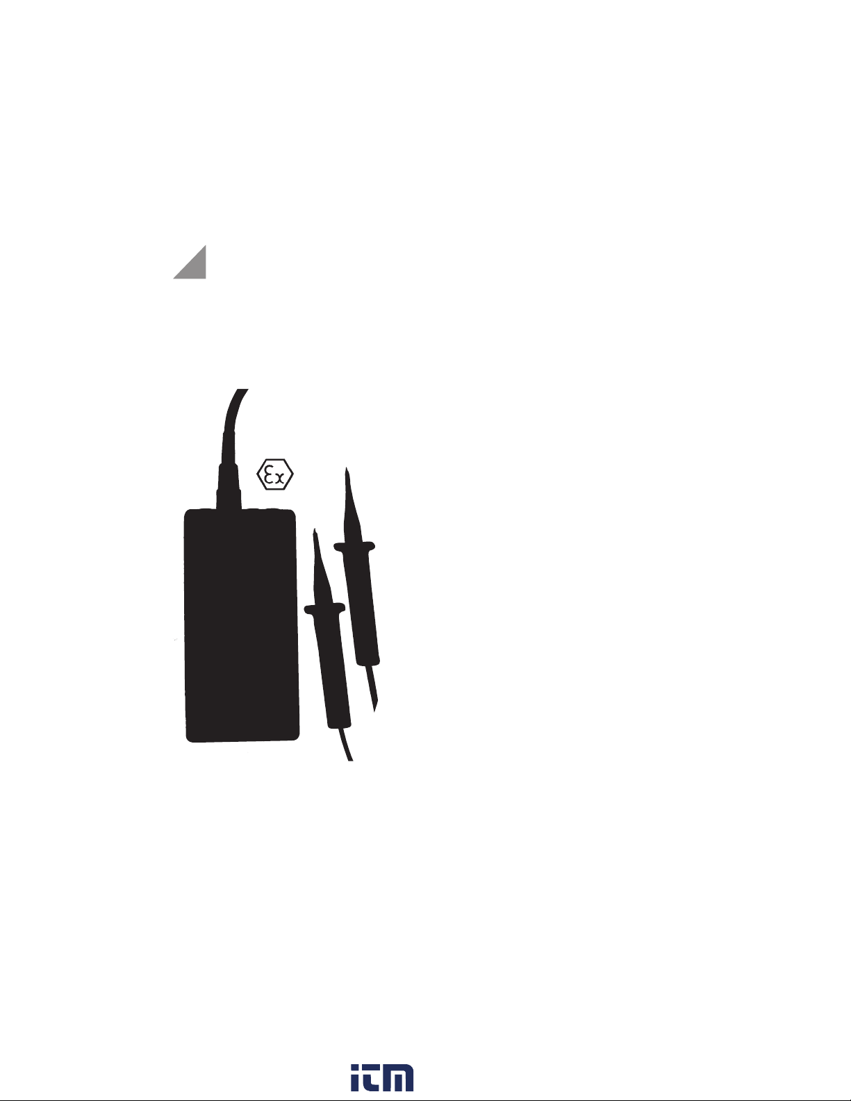
1 Test electrodes of voltage measuring line
(red conductor + /black conductor -)
2 Button DATA-HOLD
3 LED Ω (green): 0 ... 10 kΩ
4 LED Volt (red): 12 ... 1000 V
5 LCD display
6 -socket, black standard socket
7 7-pin universal connector for voltage measu-
ring lines, temperature transmitter, clamp-on
ammeter and power supply unit
8 Ω-socket, red standard socket for resistance
measurements
9 A-socket, blue standard socket
fuse socket for current measurements
10 ON/OFF button
11 Function button
12 Handgear
2
12
www. .com
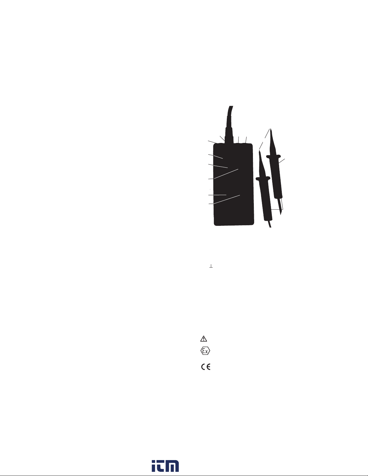
Symbols on the instrument
Attention! Observe user instructions!
Ex marking:
Approved for potentially explosive atmospheres
in accordance with ATEX (EN 60079-0 and EN
60079-11) see sectionl 5.1
EC-conformity
20
information@itm.com1.800.561.8187
Page 3

1. Application
The METRALINE EXM25 is an intrinsically safe multimeter which can be used in areas with a potentionally explosive atmosphere in accordance with ATEX
(EN 60079-0 and EN 60079-11) and EN/IEC 61010
for voltage, resistance, current, frequency measurements with measurement accessories for
measurement of temperature and high current.
Model M210A with rechargeable battery and model
M210B with Lithium battery.
1.1 Intended use
This device is intended for use in applications as
described in the operating instructions only.
Thus, it is imperative to observe the notes on safety
and the technical data in conjunction with the
ambient conditions.
Any other form of usage is not permitted and can
lead to accidents or destruction of the unit.
Any misuse will result in the expiry of all guarantee
and warrantly claims.
2. Safety Precautions
When used for its intended purpose, safety of the
operator, as well as that of the instrument, is assured.
The voltage measurement tips contain moulded
multipliers within both test prods. They are extremely safe and comply with overvoltage category CAT IV.
In order to maintain awless technical safety conditions, and to assure safe use, it is imperative that you
read these operating instructions thoroughly and
carefully before placing your instrument into service,
and that you follow all instructions contained
therein.
The device may only be used in the designated
Ex zones (see section 5.1) and inside of the safety-
related limit values (see section 5.2).
Before starting resistance measurements make
sure that the test object is at zero-potential.
Perform voltage measurements most up to the
following limits:
With probes EXM 72010 up to 1000 V
Faultless indication of display values is only
guaranteed between -10
Hold the instrument by its handgears only, to
avoid covering the display or touching the test
electrodes.
°C ... +40 °C.
21
www. .com
information@itm.com1.800.561.8187
Page 4

Only qualified persons may carry out work with
these device. The user needs to be farmiliar with
the risks for measuring and compliance
with safety regulations and the proper use of the
tester.
Workings may only be performed with appropri-
ate personal protective equipment.
Observe the minimum object distance to other
plant components that are energized or earthed
and use personal protective equipment as speci-
fied by national accident prevention regulations
(in Germany: DGUV regulation 3
previously BGV A3 or VDE 0105-100).
The function of the measuring device must be
checked briefly before and whenever possible
after the use. Carry out the function test and
check the instrument at a known voltage source
(AC and DC). If the indication of one or several
systems fails in the course of checking, the
instrument must not be used again.
The tester may only be dismantled by authorised
personnal.
Maintainance is only allowed by the manufac-
turer or explicitly authorised repair shops
(see section 7).
Before using the device check the housing and
connecting line for visible damage. If damages
are visible the voltage tester may not be placed into
operation. In case of strong dirt contamination, the
tester must be cleaned before use.
The device has to be stored in a clean and dry
environment.
www. .com
22
information@itm.com1.800.561.8187
Page 5

3. Putting into operation
3.1 Battery
Your instrument is already supplied with an energieblock. Solely use the following energyblocks:
NiMH accumulator for class I and II T4:
type Z209A EXM-AK9
Lithium battery for class I and II T6:
type Z209B EXM-LB3
Attention!
Please observe section 6 before initial startup or
after your device has been in storage for a long
period of time.
3.2 Testing display and function
At every day of use the METRALINE EXM25 has to
be checked to ensure that it works properly and
faultlessly.
Self test 1 (Display test):
Press and hold button „ON/OFF“.All display segments light up on the display, additionally the V-LED
and the Ω-LED light up. When you release button
„ON/OFF“, the value 000 ... 001 V is indicated on the
display.
Self test 2 (Voltage measuring line):
Connect and lock the voltage measurement tips
EXM 72010 to the 7-pin universal connector. Switchon the device. Display: 000..001 V, in the upper
display line 1000 V. Put the test electrodes, one after
another, inclined 5 mm into the W-socket. Display
shows ‘Test’ and ‘rdy’ and green LED lights up.
Note:
In case the display continues showing 000 V the
measurement tip is damaged, please exchange.
Self test 3 (Voltage indication):
Check functions at a known voltage source - e.g. a
230 V socket.
Self test 4 (Resistance measurement):
Put the standard test lines into the Ω- and -socket.
Adjust the device to Ω, display: OL kΩ, hold test
prods together, display indication needs to be about
0.0 Ω and the green LED needs to light up.
Attention!
If indication of one or several systems fail in the
course of performing the self test, if function standby is not indicated or if the device is damaged, the
METRALINE EXM25 must not be used again.
23
www. .com
information@itm.com1.800.561.8187
Page 6
4. Measuring and testing
4.1. General information
battery status (see section 6)
leading sign
The upper display line
shows currently selected
measurement range.
When this indication is
ashing you have to connect special accessories
e.g. TMZ or MZ
The lower display line
shows the actual
metered value.
The instrument is switched o automatically
approximately 60 seconds after the last
measurement in order to extend battery life. In the
display the indication „o“ appears (exception: see
section 4.6 frequency measurements). The backlight
turns o when no measurement result is applied or
when the battery is low.
With the ON/OFF button engaging the
METRALINE EXM25 to voltage, call the
display test and switch-o the device.
►
With the function button you can select
the designated measurement range:
Function upper
display line
Voltage with tip EXM 72010 1000 V
Voltage, automatic range mV, V AuTo
resistance
Ω
current I
current with clamp-on ammeter
I ashes*
frequency FrE
temperature with TMZ T ashes*
* When the measurement ranges are indicated by a
ashing symbol the connection of special
accessories is necessary, e.g. a clamp-on ammeter or
the temperature transmitter
www. .com
24
information@itm.com1.800.561.8187
Page 7

4.2 Testing voltage and polarity
Attention!
Connect the voltage measurement tips to the
7-pin universal connector only when the device is
switched-o. Switch-on the device not until they are
locked and select rang if necessary.
Put both test prods with safe contact onto the
metering point and the voltage value is indicated
in the lower display line.
At a voltage of 12 V ashes the red LED and button
functions are locked.
Notes:
- If Hold appears permanently, probably the tip
has been attached when the device was switched-
on. Switch METRALINE EXM25 o and on.
- Because of integrated multipliers the device indi-
cates few mV while in open-circuit operation, this
has no inuence on the result of measurement.
- The METRALINE EXM25 casing is made of
conductive material. We recommend unearthed
operation for precise voltage measurments
>100 Hz. Avoid contact with grounded parts, e.g.
control cabinet. For this purpose, the use of a
leather bag should be preferred.
1000 V voltage range (1000 V)
The voltage range adjusts automatically to the
used DATA-HOLD measurement tip EXM 72010.
The measurement range serves for a fast detection
of measurement values between 0 to 1000 V
without decimal places.
The display range of the METRALINE EXM25 extends
to 1160 V AC / 1610 V DC with EXM 72010.
Observe the safety precautions (see section 2) for
Ex-areas.
Automatic voltage range (AuTo)
The voltage range adjusts automatically to the used
voltage measurement tip EXM 72010.
The measurement range serves for a fast detection
of measurement values between 1 mV – 1000 V, the
optimal measurement range is selected automatically.
Indication of polarity
Type of voltage is indicated by the symbols
~ and – . Direct voltage: is minus applied to the test
prod with Hold button, the leading sign „-“ appears,
is plus applied, no leading sign appears in front of
the indicated value.
25
www. .com
information@itm.com1.800.561.8187
Page 8

HOLD function
The maximum voltage value can be „stored“ on the
display when activated the button „HOLD“. The value
is recorded for approx. 30 seconds or until you press
button „HOLD“ again. The Hold-function is stopped
when again a voltage is impressed.
Note: When the measured value does not vary for
2 sec, then the maximum value is recorded.
4.3 Resistance measurements (Ω)
Before taking any resistance measurements always
check that the test object is at zero-potential.
Connect 4 mm standard test lines to the Ω- and
-socket. Adjust the device to Ω. Ohm is indicated in
the upper display line.
Note:
The arrow signalizes „out of measurement range“.
The measurement range serves for a denite
determination of impedances of 0,1 Ω – 20 MΩ.
A selection between Ω-, kΩ- and MΩ ranges occurs
automatically after applying to the impedance.
The green LED signalises resistance values that a
lower than 10 kΩ.
4.4 Current measurement (I)
Attention!
You may perform current measurement in Ex-areas
only in measuring circuits with peak values of
maximum 50 V.
You may only measure currents up to maximum 2 A.
Connect 4 mm standard test lines to the A- and
-socket.
The measurement range serves for measuring
AC/DC currents in the range of 1 mA – 2 A.
A selection between mA and A occurs automatically
after attaching the test prods.
Attention!
The moulded fuse activates with currents of more
than 2 A.
The fuse can only be changed by the manufacturer
(see section 7).
4.5 Current measurement with clamp-on ammeter
MZ 1005 (I ashes)
Attention!
Measurements with MZ 1005 are only permissible
in Ex I-areas.
Please observe the separate user instructions of the
clamp-on ammeter MZ 1005. Connect the MZ 1005
to the 7-pin universal connector.
Within the clamp-on ammeter range you can measure AC/DC currents between 0,1 and 1000 A, the
optimal measurement range is selected automatically.
26
www. .com
information@itm.com1.800.561.8187
Page 9

4.6 Frequency measurements (FrE)
Connect the voltage measurement tip EXM 72010 to
the 7-pin universal connector.
The measurement range serves for measurements of
frequencies in the range of 0,1 Hz – 10 kHz with
voltages > 5 V. A selection between Hz and kHz
occurs automatically after attaching the test prods.
Note:
While the device is in open-circuit operation the
display may show 0,00 Hz/kHz ±1 digit.
With low frequencies the measurement signal needs
to be placed for a few seconds before it indicates a
reliable value.
The automatic shout-down can be deactivated by
interfering signals, e.g. because of low frequencies
with attached measurement tips.
4.7 Temperature measurements with TMZ 25
(T ashes)
Measurements with the intrinsically safe TMZ 25 and
a Fe-CuNi-sensor are only permissible in Ex I- and Ex
II-areas. Connect the TMZ 25 to the 7-pin universal
connector and plug temperature sensor on the TMZ
until it’s catched.
With the TMZ 25 you can measure temperatures between – 80 and + 600 °C. The optimal measurement
range is selected automatically.
Note:
With the universal sensor indication on the display is
rst readable after approx. 30 s, with surface sensors
after approx. 10 s. Special sensors can be delivered.
27
www. .com
information@itm.com1.800.561.8187
Page 10

5. Technical data METRALINE EXM25
pp
5.1 Identication marking / Ex zones
EC-Type Examination Certicate
BVS 13 ATEX E 089
II 2G Ex ib IIC T4/T6 Gb
I M2 Ex ib I Mb
5.2 Safety-related limit values
Intrinsically electric circuits
Voltage (by U
Internal inductance Li < 5 μH
Voltage with measurement tips:
Type EXM 72010
Class IIC AC/DC ≤ 690 V with tip EXM 72010
Class IIB AC/DC ≤ 690 V with tip EXM 72010
Class I AC/DC ≤ 1000 V with tip EXM 72010
Resistance ranges maximum values in case of fault:
Voltage 6 V
Current 2 mA
Maximum permissible external
capacitance/inductance:
Current (up to 50 V
Energie source (moulded design):
Temperature with TMZ 25:
Curent with clamp-on ammeter type MZ 1005:
= 50 V tip) 2 A
Ex group IIC 40 µF/1000mH
Ex group IIB 1000 µF/1000mH
Ex group I 3000 µF/1000mH
Frequency 2 up to 10 kHz
Uss) 2 A
internal inductance Li < 5 μH
NiMH accumulator
Type Typ Z209A/T4
Nominal voltage DC 8,4 V
Maximum voltage U
Temperature range T4
Lithium battery
Type EXM Z209B Li/T6
Nominal voltage DC 3,6 V
Maximum voltage U
Temperature range T6
(solely for class I)
AC/DC 1000 A
Frequency up to 500 Hz
0
0
-80 °C <TA< +600 °C
11,2 V
3,9 V
www. .com
28
information@itm.com1.800.561.8187
Page 11

5.3 Technical data METRALINE EXM25
Norm
EN 60079-0 and EN 60079-11 also
EN 61010-1 and 61010-031
EC type examination certicate
BVS 13 ATEX E 089
II 2G Ex ib IIC T6/T4 Gb & I M2 Ex ib I Mb
Nominal measurement ranges
usable in electricity networks group Ex I up to
1 kV, Ex IIB and Ex IIC up to 690 V
Direct current 1 kV with EXM 72010
red LED up to 12 V, LCD 3 1/2-digit:
1, 10, 100, 1000 V (1610 V),
± 1,5% + 3 digit, resolution 0,001 ... 1 V
Alternating voltage 1 kV with EXM 72010
red LED up to 12 V, LCD 3 1/2-digit, TRMS;
10, 100, 1000 V (1160 V)
± 1,5% + 3 digit up to 0 ... 100 Hz
± 5% + 5 digit up to 101 ... 500 Hz
resolution 0,01 ... 1 V
Input resistance with EXM 72010
2 MΩ distributed to 4 resistances,
moulded into DATA-HOLD test prods
Continuity/resistance
green LED LCD 3 1/2-digit
200, 2000 Ω
20, 200, 2000 kΩ, 2 MΩ, 20 MΩ ± 1 % + 5 digit,
resolution 0,1 Ω ... 10 kΩ
Current
AC/DC 1000 mA, 2 A ± 1 % + 2 digit,
resolution 1 ... 10 mA
Current with clamp
AC/DC 100, 1000 A, ± 1,5 % + 2/3 digit,
resolution 0,1 ... 1 A
Frequency
200, 2000 Hz ± 1 % + 2 digit, resolution 0,1 ... 1 Hz
10 kHz ± 3 % + 2 digit, resolution 0,01 kHz
Temperature with measurement accessory
-80 ... +150° C ± 1,5 % + 3 digit, resolution 0,1° C
-80 ... +600° C ± 1,5 % + 2 digit, resolution 1° C
Further functions
automatic selection of measurement range,
indication of function, self-test, automatic switch-o
29
www. .com
information@itm.com1.800.561.8187
Page 12

Power supply
intrinsically safe energy source, exchangeable
Li-battery (T6) or NiMH accu (T4)
exchange in Ex-areas admitted
Operating temperature
- 10°C ... + 40° C
Electromagnetic compatibility
EMV requirements DIN-EN 61326
Casing
PA impact resistant, antistatic, LCD cover
PC unbreakable
Circuit points
3 standard jacks
7-pin universal connector
Protection category
IP 54, device can be used in moist environments
Dimensions/weight
85 x 180 x 38 mm / 335 g
6. Maintainance
The METRALINE EXM25 is completely maintainancefree except for ist own energy source (see section 6.1).
Nevertheless, for safe operation observe the following
information:
The METRALINE EXM25 is to be stored in a dry place.
The plastic housing can be cleaned with a cloth dampened with alcohol (isopropyl) or soapy water.
6.1 Battery status
The latest status of the battery or the accumulator is
symbolised by a 3 stage battery symbol in the display.
=
battery full
battery half-full.
=
Many measurements still
can be performed.
=
batterie empty.
The backlight deactivates
Attention!
When the empty battery symbol ashes, taking
measurements is not possible anylonger. The battery
needs to be exchanged or the accumulator recharged
immediately.
6.2 Change battery
The change of battery is possible in Ex-areas.
Solely use the following energyblocks:
Lithium battery for class I and II T6:
type Z209B EXM-LB3
NiMH accumulator for class I and II T4:
type Z209A EXM-AK9
automatically.
30
www. .com
information@itm.com1.800.561.8187
Page 13

6.3 Load accu
Attention!
Recharge accumulators outside of Ex-areas.
6.3.1 Safety Precautions for loading
- The device NG4 is used to charge NiMH
accumulators from GOSSEN METRAWATT
(Art. no. Z209A) installed in the METRALINE EXM25.
- Lithium batteries (Art. no. Z209B) are not to be
re-charged. Attempting to recharge them may
cause risk to personal safety and damage to the
equipment.
- The charging has to be stopped manually no later
than 24 hours.
- The charger can only be connected to and
operated with 230 V AC.
- The product is only to be used in dry indoor
locations.
- avoid possible damage
- The charger and the connected METRALINE EXM25
should not be operated unattended.
- Ensure that the insulation of the housing or the
main cable is neither damaged or destroyed.
- The charger may not be placed into operation,
if the device exhibits visible damage or the device
does not operate any longer.
- The batteries may not to be opened
Depleted batteries must not be disposed with the
domestic waste. Please, return batteries at a local
retailer or municipal recycling depot.
Return is free of charge and required by law.
Technical data NG4:
Operating voltage: 230 V AC 50 Hz
Power input: ca. 5 W
Charging current: ca. 30 mA
Operating instructions: 0 ... + 40 °C
6.3.2 Recharge
Make sure a rechargeable accumulator (Art. no. Z209A)
and no battery is installed in the METRALINE EXM25.
Recharging occurs with the power supply unit NG4
without removing the accumulator from the
METRALINE EXM25:
The NG4 is connected with the 7-pin universal
connector of the EXM25 and put into the 230 V/50
Hz socket. Charging takes about 14 hours.
rel. humidity < 75 %
not condensing
.
31
www. .com
information@itm.com1.800.561.8187
Page 14

Note:
Accumulators were only shortly charged by the
manufacturer. Before the rst initial startup the akku
should be char
NiMH accumulators ist rst reached after 2 - 3 cycles
of charging and discharging.
(BAT symbol = maximum half box)
The accumulator suers damages with frequent
supercharging.
7. Maintenance
7.1 General information
The METRALINE EXM25 is absolutely mainteinancefree. Nevertheless, observe the following information
in order to maintain safe operation: Always keep the
voltage tester dry and clean. The housing can be cleaned with a cloth dampened with isopropyl (alcohol)
or soapy water.
7.2 Repeated inspection
According to EN 61243-3 it is recommended to carry
out repeated examinations.
It should not exceed the time-limit of 6 years.
Depending on operation conditions and frequency, a
previous inspection may be recommendable.
The serial number with the date of manufacturing
(WWYYNN=Week Year Number) is imprinted on the
backside of the device. Repeated inspections are
oered by the manufacturer and indicated by the
inspection plate.
7.3 Device Return and Environmentally
Compatible Disposal
The instrument is a category 9 product (monitoring
and control instrument) in accordance with ElektroG
(German Electrical and Electronic Device Law).
This device is subject to the RoHS directive.
We identify our electrical and electronic devices
in accordance with WEEE 2012/19/EU and ElektroG
with the symbol shown to the right per DIN EN
50419 .
These devices may not be disposed of with the
trash. Please contact our service department
regarding the return of old devices (address see
chapter 8).
ged for 14 hours . Full capacitance of
www. .com
32
information@itm.com1.800.561.8187
Page 15

8. Repair and Replacement Parts Service
Calibration Center
10. Limited warranty and limitation of liability
y continuous quality checks and production
B
controls, most modern electronics and high quality
materials we guarantee that the device will be free
from defects in material and workmanship for
three years.
This warranty does not cover batteries, improper
handling, not intended purpose, opening the
housing,
improper storage or damages from accidents.
No other warranties such as tness for a particular
purpose will be given.
We are not liable for any indirect, incidental or
consequential damages or losses arising from any
cause or theory.
33
www. .com
information@itm.com1.800.561.8187
Page 16

10. Accessories / Spares
Leather bag EXM-LED
Art.no. Z209L
The case for the METRALINE EXM25 and the test
cables is designed in such a way that the unit does
not have to be taken out for measurements.
Using the additional lugs and push-buttons on the
shoulder strap and case the unit can be secured in a
comfortable position to facilitate readings.
Clamp-on ammeter MZ 1005
Art. no. Z209C
for current measurements of 0,1 – 1000 A
only in Ex – I areas.
Power supply unit NG64
Art. no. Z209P
for charging the accumulator
NiMH accumulator EXM-AK9/T4
Art. no. Z209A
Lithium battery EXM-LB3 Li/T6
Art. no. Z209B
Temperature transmitter TMZ 25
Art. no. Z209T
between – 80 and + 600 °C in Ex-I and Ex–II areas
universal sensor EXM-TFU Art. no. Z209U
surface sensor EXM-TFO Art. no. Z209S
Voltage measurement tips EXM 72010
Art. no. Z209V
up to 690 V Ex II and 1000 V Ex I:
with DATA-HOLD button
www. .com
34
information@itm.com1.800.561.8187
Page 17

Quick user guide METRALINE EXM25
This quick user guide serves für a quick start. In regard
of your own safety please observe safety-related Excharacteristic values and for further information the
detailed user instructions.
Attach tips or accessories
1
Voltage Resistance Current
Ex-Group 0,1Ω - 20 MΩ 1 mA - 2 A
IIC ≤ 690 V +10 %
IIB ≤ 690 V +10 % Attention: At first Attention: Up to
I ≤ 1000 V check voltage-free max. 50 V only!
Temperature with TMZ parts!
Current with MZ
Switching-on and self-test
2
On/O/test Select function
Select range/function
3
Function upper
Voltage with tip EXM 72010 1000 V
Voltage, automatic range mV / V AuTo
resistance
current I
current with clamp-on ammeter
frequency FrE
temperature with TMZ T ashes*
battery status
leading sign
* When the measurement ranges are indicated by a ashing
symbol the connection of special accessories is necessary, e.g.
clamp-on ammeter or temperature transmitter.
display line
Ω
I ashes*
The upper display
line shows currently
selected measurement
range.
The lower display
line shows the actual
metered value.
35
www. .com
information@itm.com1.800.561.8187
 Loading...