

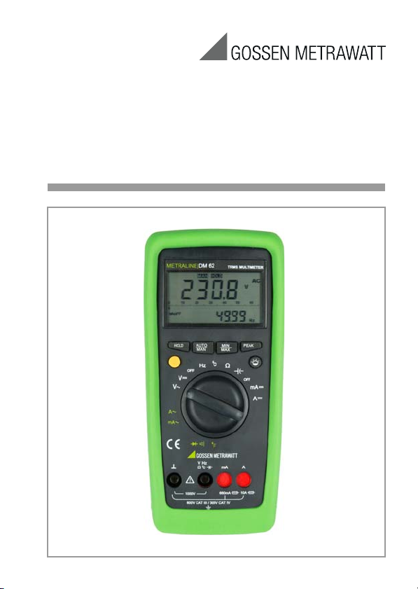
Operating Instructions
METRALINE DM 61/62
Analog-Digital Multimeter
3-447-013-03
2/7.18
+]
9
$&
$872
(10)
(11)
(18)
(20)
(12)
(21)
(11)
(19)
(16)
(15)
(14)
(17)
(15)
(13)
2 GMC-I Messtechnik GmbH

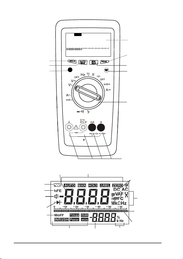
1 Liquid crystal display
2 PMAX / PMIN pushbutton
3 Pushbutton for MIN/MAX functions
4 Pushbutton for manual range selection
5 Multi function pushbutton
6 Function selector switch
7 Terminal sockets with automatic blocking system
8 Pushbutton for HOLD function
9 Pushbutton for backlight function
10 Main display for digits, decimal point and polarity
11 Display for manual range selection, Hold, MIN/MAX, Relative, Peak functions
12 Overrange indication
13 Bar graph for analog indication
14 Sub-display for digits, decimal point and polarity
15 Display for the unit of measured quantity
16 Display for indication of Auto Off Function
17 Display for diode testing
18 Buzzer indication
19 hFE: no function here
20 Low battery indication
21 Display for the selected function i. e. AC or DC
Standard Equipment
1Multimeter
1 Protective rubber cover
1Cable set
2 Batteries, 1.5 V, type AA, installed
1 Operating instructions
GMC-I Messtechnik GmbH 3

Contents Page
1 Introduction ................................................................................6
2 Safety Features and Safety Precautions ....................................6
3 Switching the Multimeter „ON“ .................................................9
4 Function and Range Selection .................................................10
4.1 Switching the Measuring Ranges .............................................................10
4.2 Auto / Manual Ranging ............................................................................10
5 Liquid Crystal Display (LCD) .....................................................11
5.1 Digital Display .........................................................................................11
5.2 Analog Indication .................................................................................... 12
5.3 Backlight ................................................................................................12
6 HOLD and Delay Hold Feature ..................................................13
6.1 HOLD Feature ......................................................................................... 13
6.2 Delay Hold Feature ..................................................................................13
7 MIN/MAX Feature .....................................................................13
8 Peak Measurement ..................................................................14
9 Voltage Measurement ..............................................................15
10 Current Measurement ..............................................................16
10.1 AC Current Measurement with (Clip-on) Current Transformer ....................17
10.1.1Transformer Output mA/A .......................................................................17
10.1.2Transformer Output V ..............................................................................18
11 Resistance Measurement ........................................................19
12 Continuity Test and Diode Test ................................................20
12.1 Continuity Test ........................................................................................20
12.2 Diode Test ..............................................................................................20
13 Capacitance Measurement (METRALINE DM 62 only) .............23
Frequency and Duty Measurement (METRALINE DM 62 only) ............ 24
14
4 GMC-I Messtechnik GmbH

14.1 Frequency Measurement .........................................................................24
14.2 Duty Cycle Measurement .........................................................................24
15 Temperature Measurement ..................................................... 25
16 Technical Characteristics ....................................................26
17 Maintenance ............................................................................32
17.1 Battery ...................................................................................................32
17.2 Fuses .....................................................................................................33
17.3 Case ......................................................................................................34
17.4 Device Return and Environmentally Compatible Disposal ...........................34
18 Product Support ....................................................................... 35
19 Repair and Replacement Parts Service
Calibration Center and Rental Instrument Service ..................35
20 Manufacturer‘s Warranty ......................................................... 36
21 Registration .............................................................................36
GMC-I Messtechnik GmbH 5

1 Introduction
Thank you very much for selecting our multimeter. These multimeters are manufactured as per IS 13875 and DIN 43751.
2 Safety Features and Safety Precautions
You have chosen a multimeter which provides you with a very
high degree of safety. The analog-digital multimeters are manufactured and tested in compliance with the safety standard
IEC 61010-1:2010/ DIN EN 61010-1:2011. In case of incorrect use or careless handling, the safety of both user and multimeter is not guaranteed.
For proper use and safe handling, it is absolutely necessary to read
and understand the operating instructions before using the multimeter.
For your safety and protection, the multimeters are fitted with
an Automatic terminal Blocking System (ABS). It is coupled
with the function selector switch which blocks the terminal
sockets not necessary for measurement.
Please note the following safety precautions
• The multimeter must be operated only by persons who
understand the danger of shock hazards and are aware of
the necessary safety precautions. Shock hazards exist
wherever voltage of more than 30 V (TRMS) is present.
• Do not work alone in shock hazardous environment while
carrying out measurements.
• The maximum permissible voltage between terminal socket
(7) and ground is 1000 V.
• Take into account that unexpected voltages may occur on
devices under test (e. g. defective instrument). For example, capacitors may be charged to a dangerously high voltage.
• Verify that the test leads are in good condition e. g. no
cracked insulation, no open circuits in the leads or connectors.
6 GMC-I Messtechnik GmbH
• This multimeter must not be used for measurements on
circuits with corona discharge (high voltage).
• Be particularly careful when measuring on HF circuits. Dangerous composite voltages may exist there. Measurements
under moist environmental conditions are not permitted.
• Do not overload the measuring ranges beyond their allowable capacities. Limit values are given in specifications, see
section 16.
• All current measuring ranges are protected with a fuse. The
maximum permissible voltage of the measuring circuit (nominal voltage of the fuse) is 1000 V AC/DC in the „mA“ and „A“
ranges.
• Protection provided by the digital multimeter may be
impaired if the multimeter is not used in a manner specified
in this user manual.
Meaning of the symbols on the device
Warning concerning a source of danger
(Attention, refer to the operating instructions)
Earth (ground) terminal.
Double or reinforced insulation
CAT II / III / IV Instrument for overvoltage
category II / III or IV
EU conformity mark
UL
GMC-I Messtechnik GmbH 7
UL approval

Opening of Equipment / Repair
The equipment may be opened only by authorized service personnel to ensure the safe and correct operation of the equipment and to keep the warranty valid.
Even original spare parts may be installed only by authorized
service personnel.
In case the equipment was opened by unauthorized personnel, no warranty regarding personal safety, measurement
accuracy, conformity with applicable safety measures or any
consequential damage is granted by the manufacturer.
Repair and Parts Replacement by Authorized Service Personnel
When the instrument is opened, voltage conducting parts may
be exposed. The instrument must be disconnected from the
measuring circuit before the performance of repairs or the
replacement of parts. If repair of a live open instrument is
required, it may only be carried out by trained personnel who
are familiar with the dangers involved.
Faults and abnormal stress:
If it has been ascertained that safe operation is no longer possible, take the multimeter out of service and secure it against
accidental use. Safe operation may not be possible
• if the multimeter shows obvious signs of damage,
• if the multimeter no longer functions correctly,
• after prolonged storage under adverse conditions,
• on account of severe stress during transport,
• if the multimeter is not being used in compliance with the
manner described in this manual.
8 GMC-I Messtechnik GmbH

3 Switching the Multimeter „ON“
Battery
Your multimeter works on 2 x AA size alkaline manganese batteries per IEC LR6. They are provided with the multimeter.
Before you use the multimeter for the first time or after storage,
refer to section 17.1. Set the rotary knob (6) to other than the
„OFF“ position to switch the multimeter ON. Switch „ON“ is
acknowledged by an acoustic signal. All segments of the LCD
will be displayed as shown on page 2.
Note:
Electric discharges and high-frequency influence may cause
incorrect information to be displayed and block the measuring
process. Reset the multimeter by switching it OFF and ON
again. Otherwise, check the battery connections. Disconnect
the multimeter from the measuring circuit before you open it,
and refer to section 17.
Automatic Meter-OFF (MoFF)
The digital multimeter has a default auto meter-off function. If
the multimeter is idle for more than 15 minutes, the multimeter
automatically turns the power off. When MoFF happens, the
state of the multimeter is saved. The „MoFF“ (16) sign on the
LCD panel indicates whether the MoFF is enabled or not. In
some cases, the user might want to disable this feature. Power
ON the multimeter by pressing any of the push functions
except for the HOLD (8) and multifunction (5) pushbuttons.
After auto meter-off, pushing any of the push functions or
changing the rotary switch mode can turn on the multimeter
again. If the multimeter is re-powered by changing the rotary
mode, the saved state is cleared. If the multimeter is re-powered by push functions, the chip restores the saved state and
enters HOLD mode. The LCD displays the saved value.
Turning the multimeter OFF
To turn OFF the multimeter, set the rotary knob (6) to the „OFF“
position.
GMC-I Messtechnik GmbH 9

4 Function and Range Selection
The function selector switch (6) is coupled with the Automatic
terminal Blocking System (ABS) which allows access only to
two correct sockets for each function. Prior to switching to the
„mA“ or „A“ functions or from the „mA“ or „A“ functions,
remove the test lead from the corresponding socket. When the
test leads are plugged in, the terminal blocking system prevents accidental switching to non permissible functions.
4.1 Switching the Measuring Ranges
The 660 mVAC and 660 mVDC measuring ranges are not
automatically selected when the multimeter is switched ON.
The above ranges can only be selected manually with the
„AUTO/MAN“ key.
4.2 Auto / Manual Ranging
The multimeter features auto ranging for all measuring ranges
with the exception of the °C, °F, continuity, Diode, %, AAC,
ADC. Autoranging is automatically selected after switching the
multimeter ON. According to the measured quantity applied,
the multimeter automatically selects the measuring range
which gives the best resolution. You can switch OFF autoranging and select the ranges manually according to the table
shown in this section. Manual mode is switched OFF when
pushbutton AUTO/MAN is pressed (4) for approximately 1 s, or
when the function selector switch (6) is operated, or when the
multimeter is turned OFF and ON again.
10 GMC-I Messtechnik GmbH
AUTO/
MAN
(4)
brief
VAC/VDC: 6.6 V → 66 V → 660 V → 1000 V →
mA AC/mA DC: 66 mA → 660 mA → 66 mA ...
Ω:660Ω→6.6 kΩ→66 kΩ→
brief
F:
Hz: 66 Hz → 660 Hz → 6.6 kHz → 66 kHz →
long Return to automatic range selection AUTO (11)
Function
Manual mode ON:
utilized measuring range is fixed
Range switching sequence for:
660 mV → 6.6 V ...
660 kΩ→6.6 MΩ→66 MΩ→660 Ω
6.6 nF→66 nF→660 nF→6.6 mF→66 mF
→
660 mF
660 kHz → 6.6 MHz → 10 MHz → 66 Hz...
6.6 mF→40 mF→6.6 nF
...
Acknow-
ledgement
Display
MAN
(11)
MAN
(11)
Note: °C, Continuity, Diode, AAC, ADC, % all functions have
fixed range.
5 Liquid Crystal Display (LCD)
5.1 Digital Display
The main digital display (10) shows the measured value with
correct location of decimal point and sign. The selected measuring unit (15) and the function (21) are simultaneously displayed. When measuring DC quantities, a minus sign appears
in front of the digits, when the positive pole of the measured
quantity is applied to the „ “ input terminal. When upper range
limit 6600 (on the range :1999) is exceeded, „OL“ is displayed. The digital display is updated 2.8 times per second.
The digital sub-display (14) shows the measured value with
correct location of decimal point and sign. The main purpose
of the two digital displays is to display simultaneous measurement as mentioned below:
GMC-I Messtechnik GmbH 11

Main Display Sub-display
Voltage Frequency
Voltage Min/Max
Frequency Duty cycle
Current Frequency
5.2 Analog Indication
The analog indication with bar graph is updated 28 times per
second. Analog indication is of particular use when observing
variations of measured values. The analog bar graph (13) has
its own polarity indication in measuring DC quantities, when
the positive pole of the measured quantity is applied to the „ “
input terminal. Analog bar graph has 65 scale divisions so that
variations of the measured values around „zero“ can be
observed exactly. The overrange is indicated by the right triangle (12) when measured value is > 6600 counts (for measurement > 1999).
5.3 Backlight
The instrument is provided with user selectable backlight for
taking measurements in poor lighting conditions/dark areas.
Switching the backlight ON
By pressing (9) key, the backlight can be switched ON for
60 s.
Switching the backlight OFF
By pressing the (9) key once again before 60 s, the backlight can be switched OFF. Otherwise it switches off automatically after 60 s.
12 GMC-I Messtechnik GmbH

6 HOLD and Delay Hold Feature
6.1 HOLD Feature
After pressing the „HOLD“ (8) button, the multimeter stops
updating the LCD panel. After enabling the HOLD function, the
multimeter switches from AUTO to the manual ranging mode,
but the measuring range remains the same.
6.2 Delay Hold Feature
The multimeter provides a delay HOLD feature. To activate the
delay HOLD feature, press the „HOLD“ (8) button for 2 seconds. The multimeter will wait for 6 seconds, then enters
HOLD mode. During the 6 second period, the HOLD symbol
on the LCD will blink and after 6 seconds, the multimeter will
hold the measured value present on the LCD. To exit the delay
HOLD function, either change range or press the „AUTO/MAN“
(4) or „HOLD“ (8) button again.
7 MIN/MAX Feature
With the MIN/MAX function, you can hold the minimum and
maximum measured value which has been applied to the input
of the multimeter after activating the MIN/MAX function. The
most important application is the determination of the minimum and maximum value for long-term monitoring of measured parameters. The actual measured value can still be
noted/read during this feature. Apply the measured quantity to
the multimeter and select the measuring range prior to activating the MIN/MAX function. With the function activated, you can
select the measuring ranges only manually, if you switch to
another range, the stored MIN/MAX values are cleared. After
pressing MIN/MAX (3) for the first time, the sub-display shows
maximum value. The sub-display shows minimum value when
it is pressed again. The main display always shows the current
value in MIN/MAX mode. To exit from this mode, either press
and hold the MIN/MAX (3) button for longer than one second,
operate the function selector switch (6) or turn the multimeter
OFF and ON again. Pressing HOLD (8) in MIN/MAX mode
GMC-I Messtechnik GmbH 13

makes the multimeter stop updating the maximum or the minimum value.
Note
MIN/MAX function is available in all measuring ranges except in
Hz.
8 Peak Measurement
METRALINE DM 61 and 62 provide a peak hold function to
capture the maximum or minimum peak value. To enter peak
mode, press the PEAK (2) pushbutton for less than 1 second.
A self-calibration process will be executed automatically before
normal peak-hold operation. In peak mode, the main display
shows the current value of signal, and the sub-display shows
the PMAX or PMIN value which is selected by the PEAK key.
After pressing the PEAK (2) pushbutton for the first time, the
sub-display shows the PMAX value. The sub-display shows
the PMIN value when the PEAK (2) pushbutton is pressed
again. To exit the PEAK-hold function, either press the PEAK
key for more than 1 second, operate the function selector
switch (6) or turn the multimeter OFF and ON again.
14 GMC-I Messtechnik GmbH

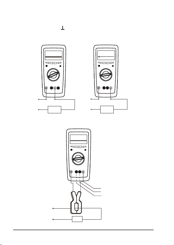
9 Voltage Measurement
a
a
+]
9
Voltage measurement
According to the voltage to be measured, set the function
selector switch (6) to V AC or V DC. Connect the test leads as
shown. The „ “ socket should be connected to the lowest
potential ground available. In V AC mode, the main display
always shows voltage and the sub-display shows frequency.
Note
The 660 mV measuring ranges can only be selected manually
with the „AUTO/MAN“ (4) pushbutton.
Caution
Ensure that the current
measuring range („mA“ or
„A“) is not selected during
voltage measurement! If
the cut-out rating of the
fuses is exceeded due to
improper operation, a
dangerous situation may
occur!
GMC-I Messtechnik GmbH 15

10 Current Measurement
• First disconnect the power supply to the circuit being measured and/or to the load, and discharge all capacitors
within that circuit.
• With the function selector switch (6), select A for currents
> 660 mA and mA for currents ≤ 660 mA. When measuring current of unknown magnitude, select the highest measuring range first.
• Select the function corresponding to the measured quantity by briefly pressing the yellow multi-function (5) pushbutton.
• Each time the pushbutton is pressed, alternate switching
takes place between DC and AC. The change-over is
acknowledged by an acoustic signal.
• The symbols DC and AC (21) are displayed as per selected
function on the LCD.
• When selecting a range with the function selector switch
(6), the DC function is always set by default.
• Connect the multimeter in series with the load, as shown.
Ensure that the connections are tight (with least resistance).
Notes on current measurement
• The multimeter must be used only in the power systems,
where the current circuit is protected by a fuse or a circuit
breaker of 20 A, and when the nominal voltage of the system does not exceed 1000 V AC/DC.
• Carefully secure the measuring circuit connections by
mechanical means so that they do not accidentally open.
The conductor cross sections and connection points
should be designed so as to avoid excessive heating.
• The current measuring ranges up to 660 mA are protected
against a short circuit current of 25 A by a 1.6 A/
1000 V AC/DC fuse in conjunction with power diodes.
16 GMC-I Messtechnik GmbH

The cut-out capacity of the fuse is 10 kA at a rated voltage
of 1000 V AC/DC and ohmic load.
• The 10 A current measuring ranges are protected by a
10 A / 1000 V AC/DC fuse. The cut-out capacity of the
fuse is 30 kA at a nominal voltage of 1000 V AC/DC and
ohmic load.
• Replacement of the fuses is described in section 17.
10.1 AC Current Measurement with (Clip-on) Current Transformer
10.1.1 Transformer Output mA/A
Caution
If current transformers are operated with an open circuit on the
secondary side, e. g. due to defective or disconnected leads, a
blown fuse in the multimeter, or a wrong connection, dangerously high voltages may occur at the connectors. Therefore,
make sure that the current circuit of the multimeter and secondary winding of the transformer connected to the multimeter
form an intact circuit. Connect the transformer to the and
mA or A sockets. The maximum permissible operating voltage
is the nominal voltage of the current transformer. When reading
the measured value, take into account the transformer ratio
and the additional error in indication.
Transformer output METRALINE DM 61
The METRALINE DM 61 shows the switching position and the
corresponding sockets. Connect a (clip-on) current transformer with a transmission ratio of 1000:1 to this socket. The
measured values are then displayed directly in the „A“ range.
GMC-I Messtechnik GmbH 17
10.1.2 Transformer Output V
P$
a
a
+]
P
$
$
a
a
+]
$
a
$
P$
9
+]
$
a
AC current measurement with (clip-on) current transformers
Current measurement
Many transformers have a voltage output (referred to as mV/A).
The secondary output must therefore be connected to the
connection sockets „“ and „V“.
18 GMC-I Messtechnik GmbH

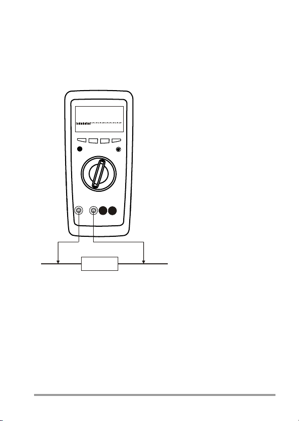
11 Resistance Measurement
• Verify that the device under test is electrically dead.
External voltages would falsify the measured result!
• Set the function selector switch (6) at „Ω“
• Connect the device under test as shown.
Zero adjustment on the 660 Ω measuring range
When measuring small resistance values on the 660 Ω range,
you can eliminate the resistance of the leads and contact resistance by means of the REL function.
• Connect the test leads with the multimeter and join the free
ends.
• Press and hold the PEAK (2) key and press the AUTO/MAN
(4) pushbutton. The multimeter enters into the „REL“ mode.
The „REL“ symbol is displayed on the LCD.
• The value „00.00“ (+1 digit) is shown on the main display
while the resistance value measured at the time of pressing
the pushbuttons is indicated on the sub-display and used
as reference value.
• This value is automatically deducted from the values measured subsequently.
The REL function can be cleared
• by pressing and holding the PEAK pushbutton and then
pressing the AUTO/MAN key. This is acknowledged by
acoustic signals.
• by switching the multimeter off.
.
GMC-I Messtechnik GmbH 19
12 Continuity Test and Diode Test
• Verify that the device under test is electrically dead. External voltages would falsify the measured results!
12.1 Continuity Test
• Set the function selector switch (6) at „Ω“, then press the
yellow multi-function pushbutton (5). The multimeter
acknowledges turn-ON with an acoustic signal.
• At the same time, (18) appears on the LCD and „OL“ is
displayed on the main display.
• An acoustic signal is generated whenever the reading is
less than 30 Ω.
12.2 Diode Test
• Set the function selector switch (6) at „Ω“, then press the
yellow multi-function pushbutton (5) twice. The multimeter
acknowledges turn ON with an acoustic signal.
• At the same time, (18) appears on the LCD and „OL“ is
displayed on the main display.
• The multimeter displays the forward voltage in Volts.
• As long as the voltage drop does not exceed the maximum
display value of 1.999 V, you can also test several seriesconnected elements or reference diodes with a small reference voltage.
• Reverse direction or open circuit: the multimeter indicates
overrange „OL“.
• With the diode function selected, the multimeter emits a
continuous acoustic signal whenever the reading is less
than 30 mV.
Note
Resistors and semiconductor junction in parallel with the diode
falsify the measured results!
20 GMC-I Messtechnik GmbH
Changing between resistance, continuity, diode testing
.
"
Resistance Measurement
Repeated brief pressing of the yellow multi-function switch (5)
changes the measuring functions in the following order:
Resistance → Continuity → Diode → Resistance...
GMC-I Messtechnik GmbH 21
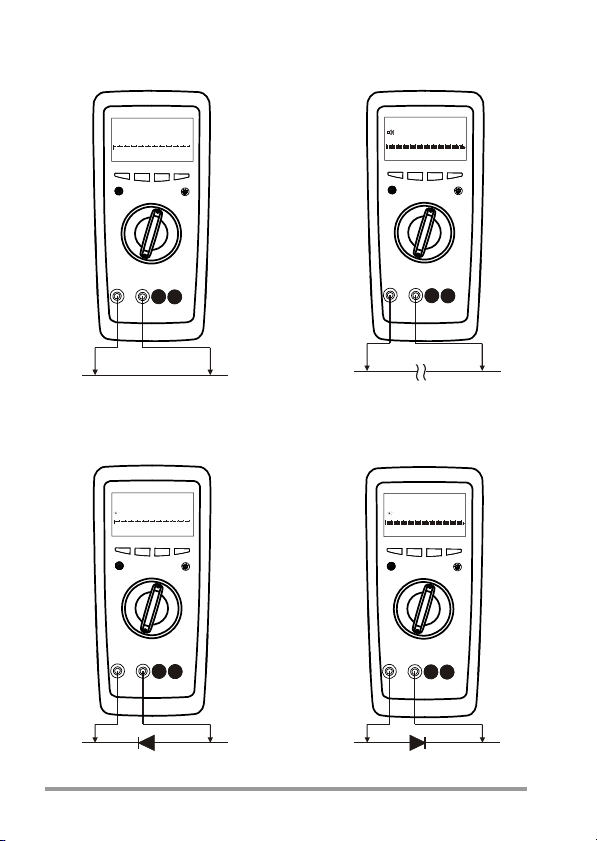
"
O
"
O
9
9
Continuity Test
Diode Test
Forward direction Reverse direction
22 GMC-I Messtechnik GmbH
13 Capacitance Measurement (METRALINE DM 62 only)
• Verify that the device under test is electrically dead. External voltages would falsify the measured results!
• Set the function selector switch (6) at „ “.
• Connect the (discharged !) device under test to the „ “
and „ “ sockets via test lead.
Note
• Connect polarized capacitors with the „–“ pole to the „ “
socket.
• Resistors and semiconductor junctions in parallel with the
capacitor falsify the measured results!
Zero adjustment on the 6.600 nF measuring range
When measuring small capacitance values on the 6.600 nF
range, the internal resistance of the multimeter and the capacitance of the leads can be eliminated by the „REL“ function.
• Connect the test leads to the multimeter without a device
under test.
• Press and hold the PEAK (2) key and press the AUTO/MAN
(4) pushbutton. The multimeter enters into the „REL“ mode.
The „REL“ symbol is displayed on the LCD. The value
„00.00“ (+1digit) is shown on the main display while the
capacitance measured at the time of pressing the pushbuttons is displayed on the sub-display and used as a reference value. This value is automatically deducted from the
values measured subsequently.
The REL function can be cleared
• by pressing and holding the PEAK pushbutton and then
pressing the AUTO/MAN key. This is acknowledged by
acoustic signals.
• by switching the multimeter off.
GMC-I Messtechnik GmbH 23

14 Frequency and Duty Measurement (METRALINE DM 62 only)
Duty cycle (%) =
Pulse duration
Cycle duration
x 100
14.1 Frequency Measurement
• Set the function selector switch (6) at „Hz“
• The multimeter switches to frequency measurement. The
frequency is displayed on the main display and duty cycle
is displayed on the sub-display. See section 16 for the lowest measurable frequencies and the maximum permissible
voltages.
• Connections are established in the same way as for voltage measurement.
14.2 Duty Cycle Measurement
With duty cycle measurement, the user can determine the ratio
of pulse duration to cycle time of recurring square-wave signals.
• Set the function selector switch (6) at „Hz“.
• The multimeter switches to frequency measurement. The
frequency is displayed on the main display and duty cycle
is displayed on the sub-display.
• The duty cycle (i.e. the percentage pulse duration of a signal) is displayed on the LCD in %
•That is:
Note
• The applied frequency must remain constant during duty
cycle measurement.
24 GMC-I Messtechnik GmbH

15 Temperature Measurement
The METRALINE DM 61 and METRALINE DM 62 multimeters
allow the user to measure temperature with a K type thermocouple in the range from –50 °C ... 1300 °C.
• Set the function selector switch (6) at „°C“
• Connect the multimeter probe with the two unblocked terminals and the thermocouple output.
• The multimeter measures temperature in °C.
• To measure temperature in F, press the yellow multi-function pushbutton (5).
Changing between °C and °F
Repeated brief pressing of the yellow multi-function switch (5)
changes the measuring functions in the following order:
°C → °F → °C ....
The analog scale is disabled in temperature measurement
mode.
GMC-I Messtechnik GmbH 25

16 Technical Characteristics
Meas.
Measuring
Func-
Range
tion
660.0 mV • • 100 μV
6.600 V • • 1 mV
V(DC)
66.00 V • • 10 mV
660.0 V • • 100 mV
1000 V • • 1 V
660.0 mV • • 100 μV
6.600 V • • 1 mV
V(AC)
66.00 V • • 10 mV
660.0 V • • 100 mV
1000 V • • 1 V
66.00 mA • • 10 μA 66.00 mV 0.8 + 5
A(DC)
660.0 mA • • 100 μA 66.00 mV 0.8 + 5
10.00 A — • 10 mA 10.00 mV 1.5 + 5 12 A cont.
66.00 mA • • 10 μA 66.00 mV 0.8 + 5
A(AC)
660.0 mA • • 100 μA 66.00 mV 0.8 + 5
10.00 A — • 10 mA 10.00 mV 1.5 + 5 12 A cont.
66.00 A • — 10 mA 66.00 mV 0.8 + 5
5)
(AC)
660.0 A • — 100 mA 66.00 mV 0.8 + 5
660.0 Ω • • 100 mΩ –3.3 V 0.8 + 5
6.600 kΩ ••1 Ω –1.08 V 0.8 + 5
66.00 kΩ • • 10 Ω –1.08 V 0.8 + 5
Ω
660.0 kΩ • • 100 Ω –1.08 V 0.8 + 5
6.600 MΩ ••1 kΩ –1.08 V 1.0 + 5
66.00 MΩ • • 10 kΩ –1.08 V 2.0 + 5
DM61 DM62
(TRMS)
Resolution
Input
Impedance
>100 MΩ //
<40pF
11 MΩ //<40pF
10 MΩ // <40pF
10 MΩ // <40pF
10 MΩ // <40pF
>100 MΩ //
<40pF
11 MΩ //<40pF
10 MΩ // <40pF
10 MΩ // <40pF
10 MΩ // <40pF
Voltage Drop
no-load Voltage
Digital display inherent
deviation at
referen ce
condition
+(...% rdg.
+...digits)
0.7 + 5
0.4 + 5
0.4 + 5
0.4 + 5
0.4 + 5
1.2 + 5
1.0 + 3
Overload
Capacity
1)
Over-
Over-
load
load
Values
Duration
1000 V
DC
AC
cont.
eff/rms
sine
wave
0.7 A cont.
0.7 A cont.
0.7 A cont.
1000 V
DC
AC
max.
eff/rms
10 s
sine
wave
26 GMC-I Messtechnik GmbH

Meas.
Function
Measuring
Range
DM61 DM62
660.0 Ω • • 100 mΩ
(TRMS)
tion
Input
Impedance
Digital display inherent
deviation at
referen ce
condition
+(...% rdg.
+...digits)
–3.3 V 0.8 + 5
Resolu-
DIODE 2.000 V • • 1 mV 3.3 V 2.0 + 10
6.600 nF — • 1 pF
3.0 + 40
66.00 nF — • 10 pF 2.0 + 10
660.0 nF — • 100 pF 2.0 + 10
6.600 μF — • 1 nF 2.0 + 10
F
66.00 μF — • 10 nF 2.0 + 10
—
660.0 μF — • 100 nF 5.0 + 10
6.600 mF — • 1 μF 5.0 + 10
40.00 mF — • 10 μF 5.0 + 10
66.00 Hz — • 0.01 Hz
660.0 Hz — • 0.1 Hz
6.600 kHz — • 1 Hz
66.00 kHz — • 10 Hz
Hz
10 Hz (f min) 0.2 + 2
660.0 kHz — • 100 Hz
6.600 MHz — • 1 kHz
10.00 MHz — • 10 kHz
1.0 ... 98.90%
%
0 ... 1300 °C
°C/°F
–50 ... 0 °C
1)
at 0 °C ... + 40 °C
2)
at input > 3.5 Vrms
3)
for < 10 kHz at 5 Vp-p
4)
without sensor
5)
display with current transformers 1000:1
— • 0.01 %
••1°
••1°
C
C
0.9% (% min)
—2,0 ±3
—2,0 ±10
10 Hz ... 1 kHz
±5 digit 3)
1...10 kHz;
±
5 digit/kHz
2)
4)
4)
Overload
Capacity
Overload
Values
1000 V
DC
AC
eff/rms
sine
wave
1)
Overload
Duration
max.
10 s
GMC-I Messtechnik GmbH 27

Influencing quantities and influence error
Influencing
Quantity
Temperature
Range of Influence
0 °C ... +21 °C
and
+25 °C ... +40 °C
20 Hz ... < 50 Hz
> 50 Hz ... 200 Hz 5.0 + 3
Measured
quantity
frequency
20 Hz ... < 50 Hz
>50Hz...2kHz 5.0+7
> 50 Hz ... 200 Hz
20 Hz ... < 2 kHz 5.0 + 3
Crest
factor CF
4)
Battery
voltage
... < 2.49
V
> 2.49 V ... 3 V
75%
Relative
humidity
3 days
Meter off
1)
with temperature: Error data apply per 10 K change in temperature.
With frequency: Error data apply to a display from 300 digits onwards.
2)
with unknown waveform (crest factor CF > 2), measure with manual range
selection
3)
with the exception of sinusoidal waveform.
4)
after the „ “ symbol is displayed.
1 ... 1.4
1.4 ... 5
Measured Quantity/
Measuring Range
±(... % of rdg. + ... digits)
V DC, V AC
A DC, A AC
Ω
1 x intrinsic uncertainty/K
Diode
F, Hz, %, °C
660 mV~
66 ... 1000 V~
A~
3)
3)
, A~
V~
2)
V DC 5 digit
V~, A DC 10 digit
A AC 6 digit
660 Ω 4digit
6.600 kΩ ...
66.00 MΩ
nF, F, mF, Hz, % 5 digit
V~, V DC
A~, A DC
Ω
F
Hz
°C
%
Variation 1)
1.0 + 3
1.0 + 3
1.0 + 3
±1% of rdg.
±5% of rdg.
3digit
1 x intrinsic uncertainty
28 GMC-I Messtechnik GmbH

Influencing
Quantity
Common Mode
Interference
Volt age
Normal Mode
Interference
Volt age
Range of Influence
Noise quantity max. 1000 V
Noise quantity max. 1000 V
50 Hz, 60 Hz sinusoidal
Noise quantity: V ,
value of the measuring range at a time
max. 1000 V , 50 Hz, 60 Hz sinusoidal
Noise quantity max. 1000 V V > 45 dB
Measuring
Range
V > 100 dB
V > 100 dB
V > 100 dB
V>50dB
660 mV, 6.6 V,
660 V, 1000 V
DC
66 V DC > 35 dB
Attenuation
> 43 dB
Display
Liquid crystal display (58 mm x 31.4 mm) with analog indication and digital display with display of the unit of measured
quantity, function and various special functions.
Analog
Indication LCD scale with bar graph
Scale length 55 mm
Scaling 65 scale divisions during all the mea-
surement
Polarity indication With automatic reversal
Overrange indication By triangle
Sampling rate 28 times/s
Digital
Height of main
display numerals 7 segment numerals: 12 mm
Height of subdisplay numerals 7 segment numerals: 7 mm
Number of counts 4 digit: 6600 counts
Overrange display „OL“ is shown
Polarity display „–“ sign is shown
when positive pole connected to „ “
Sampling rate 2.8 times/s
GMC-I Messtechnik GmbH 29

Power supply
Battery 2 x AA size alkaline manganese
batteries per IEC LR6.
Service life for METRALINE DM 61:
600 hrs. for V DC, A DC
300 hrs. for V AC, A AC
for METRALINE DM 62:
400 hrs. for V DC, A DC
200 hrs. for V AC, A AC
Battery test Automatic display of „ “ symbol
when battery voltage falls below following value: approx. 2 V.
Electromagnetic compatibility (EMC)
Emission EN 61326: 2013 Class B
Immunity IEC 61000-4-2:
8 kV atmospheric discharge
4 kV contact discharge
IEC 61000-4-3: 3 V/m
Short-term measured value deviation may occur during electromagnetic interference thus reducing the specified operating quality.
Safety: IEC 61010-1-2010
Measuring category 600 V CAT II I, 300 V CAT IV
The maximum voltage of 1000 V may
only be used with CAT I I.
High Voltage Test 6.7 kV (IEC 61010-1-2010)
Fuse for up to 660 mA ranges
FF (UR) 1.6 A / 1000 V AC/DC; 6.3 mm X 32 mm; rating 10 kA
with 1000 V AC/DC and ohmic load; in conjunction with power
diodes, protects all current measuring ranges up to 660 mA.
Fuse for up to 10 A ranges (METRALINE DM 62)
FF (UR) 10 A / 1000 V AC/DC; 10 mm x 38 mm; rating 30 kA
with 1000 VAC/DC and ohmic load; protects the 10 A ranges
up to 1000 V AC/DC, see section 17 for types of fuses.
Note: Defective fuses are not displayed!
30 GMC-I Messtechnik GmbH

Response Time (after manual range selection)
Measured Quantity/
Measuring Range
V , V , °C 0.1 s 1 s from 0 to 80%
A , A 0.1 s 1 s
660 Ω ... 6.6 MΩ 0.1 s 1 s
66 MΩ 0.2 s 2 s
6.6 nF ... 66 μF 0.7 s max. 1 s
660 μF ... 6.6 mF 1.4 s max. 3 s
66 mF 7.0 s max. 15 s
660 Hz, 6.6 kHz 2.0 s max. 2 s
66 kHz, 660 kHz, 1 MHz 0.5 s max. 1 s
% (≥ 10 Hz) 0.7 s max. 2.5 s
Response Time
Analog
Display
Digital Display
0.1 s 1 s
Transient response for
step function of the
measured quantity
of the upper range limit
from 0 to 50%
of the upper range limit
from 0 to 80%
of the upper range limit
Reference conditions
Ambient temperature 23 °C+ 2 K
Relative humidity 45% ... 55 % RH
Frequency of
measured quantity 50 or 60 Hz ±2%
Waveform of the
measured quantity sinusoidal
Battery voltage 3 V ±0.1 V
Environmental conditions
Functional
temperature range –10 °C ... 50 °C
Storage
temperature range –25 °C ... +70 °C (without batteries)
Relative humidity 45 ... 75 %
Altitude up to 2000 m
Mechanical configuration
Protection for the multimeter
IP52
Pollution degree 2
Connection sockets IP20 according to EN 60529
GMC-I Messtechnik GmbH 31
Dimensions 86 mm x 185 mm x 55 mm
Attention!
!
+
Weight
480 g approx., including battery and holster
17 Maintenance
Caution
Disconnect the multimeter from the measuring circuit before
you open it to replace the battery or the fuse!
17.1 Battery
Prior to initial start-up or after storage of multimeter, verify that
the batteries inserted in the multimeter do not leak. Repeat this
check at regular brief intervals. If the batteries are leaking,
remove them carefully and entirely with a moist cloth and install
new batteries before putting the multimeter back into operation. When the symbol „ “ (17) appears on the LCD (1),
replace the batteries as soon as possible. Although measurements can still be performed, a reduced measuring accuracy
must be taken into account in this case.
ates with 2 x AA size alkaline manganese batteries per IEC LR6.
Replacing the Battery
➭ Place the multimeter on its face, loosen the single screw on
the rear side and remove the battery cover.
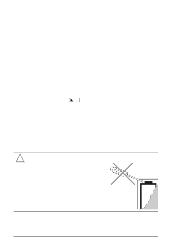
Remove the batteries by levering out the negative pole of
the batteries with a screw
driver first. Otherwise, the
contacts of the positive pole
in the battery compartment
might be damaged and the
battery lead severed.
➭ Remove the batteries from the battery compartment and
replace them with new ones (for technical specifications
refer to sub-section „Power supply“).
The multimeter oper-
32 GMC-I Messtechnik GmbH

Attention!
!
When inserting the batteries, begin with the positive
pole of the battery and fit the negative pole into place
afterwards, in order to avoid damage to the contacts of
the positive pole.
➭ Tighten the battery cover with the screw.
17.2 Fuses
The 10 A fuse protects the 10 A range, the 1.6 A fuse protects
the 66 mA, 660 mA current measuring ranges. When a fuse
blows, eliminate the cause of the overload before using the
multimeter again!
Replacing the Fuses
• Place the multimeter on its face, loosen the two bottom
cover screws on the rear and remove the bottom cover by
lifting it from the bottom.
• Remove the defective fuse from the fuse holders.
• Remove the blown fuse, e. g. with the aid of a probe, and
replace it with a new one.
• Tighten the bottom cover with the two screws.
Fuse types for current measuring ranges up to 660 mA:
– FF (UR) 1.6 A / 1000 V AC/DC; (10 kA); 6.3 mm x 32 mm
For 10 A current measuring range:
– FF (UR) 10 A / 1000 V AC/DC; (30 kA); 10 mm x 38 mm
Caution
It is imperative to ensure that only the fuses specified above
are installed!
If a fuse of other cut-out capacity, other nominal current or
other switching capacity is used, a dangerous situation exists,
and there is a risk of damaging protective diodes, resistors or
GMC-I Messtechnik GmbH 33

other components. The short-circuiting of the fuse holder is
Pb Cd Hg
not permissible.
17.3 Case
No special maintenance is required for the housing. Keep outside surfaces clean. Use a slightly dampened cloth for cleaning. Avoid the use of cleansers, abrasives or solvents.
17.4 Device Return and Environmentally Compatible Disposal
The instrument is a category 9 product (monitoring and control
instrument) in accordance with ElektroG (German Electrical
and Electronic Device Law). This device is subject to the RoHS
directive. Furthermore, we make reference to the fact that the
current status in this regard can be accessed on the Internet at
www.gossenmetrawatt.com by entering the search term
WEEE.
We identify our electrical and electronic devices in
accordance with WEEE 2012/19/EU and ElektroG
using the symbol shown at the right per
DIN EN 50419.
These devices may not be disposed of with the trash.
Please contact our service department regarding the return of
old devices (see address in Section 19).
If you use batteries or rechargeable batteries in your instrument or
accessories which no longer function properly, they must be
duly disposed of in accordance with the applicable national
regulations.
Batteries or rechargeable batteries may contain harmful substances or heavy metals such as lead (Pb), cadmium (Cd) or
mercury (Hg).
The symbol shown at the right indicates that batteries
or rechargeable batteries may not be disposed of with
the trash, but must be delivered to collection points
specially provided for this purpose.
34 GMC-I Messtechnik GmbH

18 Product Support
If required please contact:
GMC-I Messtechnik GmbH
Product Support Hotline
Phone +49 911 8602-0
Fax +49 911 8602-709
E-Mail support@gossenmetrawatt.com
19 Repair and Replacement Parts Service
Calibration Center* and Rental Instrument Service
If required please contact:
GMC-I Service GmbH
Service Center
Beuthener Straße 41
90471 Nürnberg, Germany
Phone: +49 911 817718-0
Fax: +49 911 817718-253
E-mail service@gossenmetrawatt.com
www.gmci-service.com
This address is only valid in Germany.
Please contact our representatives or subsidiaries for service in
other countries.
* DAkkS Calibration Laboratory for Measured Electrical Quantities
D-K-15080-01-01 accredited per DIN EN ISO/IEC 17025
Accredited quantities: direct voltage, direct current value, direct current resistance, alternating voltage, alternating current value, AC active power, AC apparent power, DC power, capacitance, frequency, temperature
GMC-I Messtechnik GmbH 35

20 Manufacturer‘s Warranty
Digital multimeters of the METRALINE DM series are guaranteed for a period of 3 years after shipment. The manufacturer’s
warranty covers materials and workmanship. Damages resulting from use for any other than the intended purpose or operating errors, as well as any and all consequential damages, are
excluded.
Kindly register each device at myGMC after purchase in order
to benefit from the 3 year warranty.
21 Registration
Register your device at www.gossenmetrawatt.com → myGMC
Your Benefits for your digital multimeter
• Backup for serial number
• Free downloads
• Info hotline
• Update information
• Application notes
Edited in Germany • Subject to change without notice • A pdf version is available on the
Internet
GMC-I Messtechnik GmbH
Südwestpark 15
90449 Nürnberg •
Germany
Phone +49 911 8602-111
Fax +49 911 8602-777
E-Mail
info@gossenmetrawatt.com
www.gossenmetrawatt.com
 Loading...