

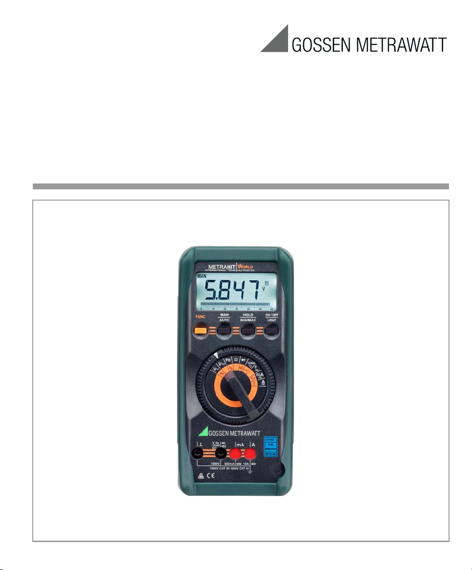
Operating Instructions
METRAHITWORLD
International TRMS Multimeter
3-349-529-03
10/6.17
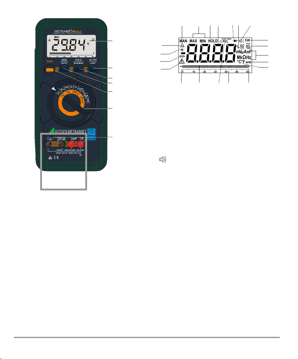
1 Display (LCD)
1
2
3
4
5
6
7
Max.
1000 V !
14
542
12
13
9
1516
19
18
21
71 3
10
17
20
8
6
11
2 ON / OFF
3 HOLD Key for the following functions: save
4 MAN / AUTO Key for manual measuring range selection
5 FUNC Key for selecting ranges or functions
6 rotary selector switch for measuring functions
7 Connector jacks
Light
Key for ON / OFF and display illumination
ON / OFF
measured value, delete and MAX-MIN
Symbols used in the Digital Display
1 MAN: manual measuring range selection is active
2 MAX/MIN value storage
3 HOLD: display memory, “freeze” measured value
4 Digital display with decimal point and polarity display
5 Diode measurement selected
6 Display Duty Cycle Measurement
7 appears when acoustic signal is active
8 Selected type of current
9 interface active
10 Unit of measure
11 Unit of measure C / F for temperature measurement
12 Rotation Per Minute measurement selected
13 Triangle appears: indicates overranging
14 Pointer for analog display
15 REL: relative measurement with reference to offset
16 Scale for analog display
17 Indicates that the negative analog display range has been exceeded
18 Warning regarding dangerous voltage: > 40 V AC / 60 DC
19 Display in case of defective fuse
20 Low battery display
21 Symbol for continuous duty
2 GMC-I Messtechnik GmbH
Standard Equipment
1 TRMS-digital multimeter
1 Protective rubber holster
2 1.5 V AA size batteries
1 Set of measurement cables KS17-2
1 DAkkS calibration certificate
1 Short-form operating instructions

Table of Contents
Page Page
1 Safety Features and Precautions ...............................3
2 Initial Start-Up ............................................................5
3 Selecting Measuring Functions and Measuring
Ranges .......................................................................5
3.1 Automatic Measuring Range Selection .....................................5
3.2 Manual Measuring Range Selection .........................................5
3.3 Quick Measurements ..............................................................5
3.4 Relative Measurement D REL ................................................... 6
4 LCD .............................................................................6
4.1 Digital Display ......................................................................... 6
4.2 Analog Display ........................................................................ 6
4.3 Display Illumination .................................................................6
5 Measured Value Memory “HOLD” ..............................6
6 Saving Minimum or Maximum Values
“MIN/MAX” Hold .........................................................6
7 Voltage Measurement ................................................7
7.1 Sub-function Hz ...................................................................... 7
8 Current Measurement ................................................8
8.1 Measuring Alternating Current with (Clip-On) Current
Transformers ........................................................................ 10
8.1.1 Transformer Output mA / A ...................................................10
8.1.2 Transformer Output V ............................................................ 10
9 Resistance Measurement .........................................10
10 Continuity and Diode Testing ...................................11
11 Capacitance Measurement ......................................12
12 Frequency Measurement –
Duty Cycle Measurement .........................................12
12.1 Duty Cycle Measurement ....................................................... 12
12.2 RPM Measurement ...............................................................12
13 Temperature Measurement ......................................13
14 Characteristic Values ...............................................14
15 Maintenance ............................................................17
15.1 Battery ................................................................................. 17
15.2 Fuses ...................................................................................17
15.3 Housing ................................................................................ 17
16 Recalibration ............................................................18
17 Accessories ............................................................. 18
17.1 General ................................................................................ 18
17.2 Technical Data for Measurement Cables
(included: KS17-2 safety cable set) ........................................ 18
18 Repair and Replacement Parts Service,
Calibration Center and Rental Instrument Service ... 19
19 Manufacturer’s Guarantee ....................................... 19
20 Product Support ....................................................... 19
1 Safety Features and Precautions
You have selected an instrument which provides you with a
high level of safety.
This instrument fulfills the requirements of the applicable EU
guidelines and national regulations. We confirm this with the
CE marking. The relevant declaration of conformity can be
obtained from GMC-I Messtechnik GmbH.
The analog-digital multimeter is manufactured and tested in
accordance with safety regulations IEC 61010–1:2010/
DIN EN 61010–1:2011/VDE 0411–1:2011. When used for its
intended purpose, safety of the operator, as well as that of
the instrument, is assured. Their safety is however not
guaranteed, if the instrument is used improperly or handled
carelessly.
In order to maintain flawless technical safety conditions, and to
assure safe use, it is imperative that you read the operating
instructions thoroughly and carefully before placing your instrument
into service, and that you follow all instructions contained therein.
In the interest of your own safety and in order to protect the
instrument, the multimeter is equipped with an automatic
socket blocking mechanism. This mechanism is linked to the
function selector switch and only allows access to those
jacks which are actually required for the selected function. It
also prevents the user from turning the selector switch to
impermissible functions after the measurement cables have
already been plugged in.
Observe the following safety precautions:
• The instrument may only be operated by persons who
are capable of recognizing contact hazards and taking
the appropriate safety precautions.
anywhere, where voltages of greater than 33 V
• Avoid working alone when taking measurements which
involve contact hazards. Be certain that a second person
is present.
• Maximum allowable voltage between any of the connector
jacks and earth is 1000 V, category III or 600 V CAT IV.
Nominal voltage at the system may not exceed 600 V.
For the application of measuring cables see chap. 17.2.
Contact hazards exist
may occur.
RMS
GMC-I Messtechnik GmbH 3
Voltage measurement may only be performed with the
Warning!
!
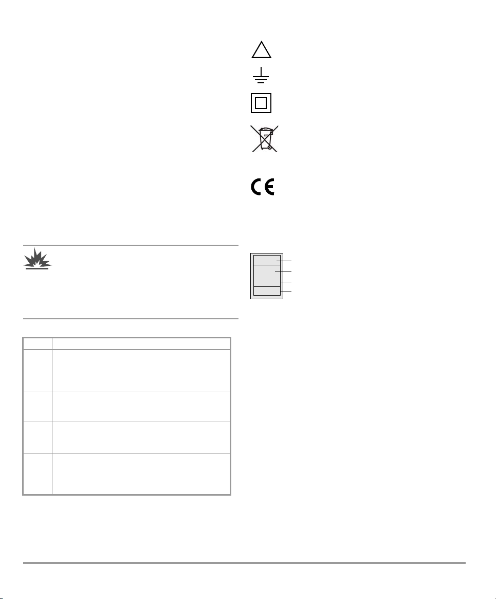
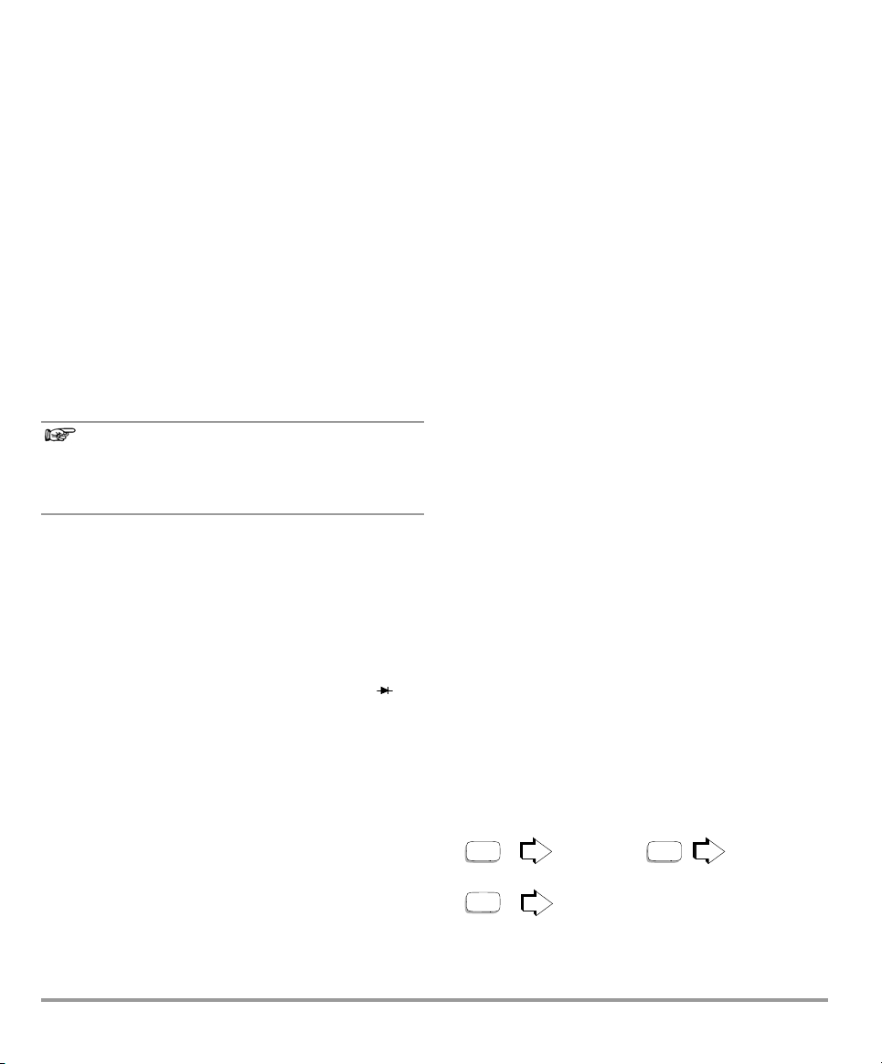
Consecutive number
Registration number
Date of calibration (year - month)
Deutsche Akkreditierungsstelle GmbH – calibration laboratory
XY123
2012-07
D-K-
15080-01-01
selector switch set to the V= or the V~ position.
• Be prepared for the occurrence of unexpected voltages
at devices under test (e.g. defective devices). For
example, capacitors may be dangerously charged.
• Make certain that the measurement cables are in flawless
condition, e.g. no damage to insulation, no interruptions
in cables or plugs etc.
• No measurements may be made with this instrument in
electrical circuits with corona discharge (high-voltage).
• Special care is required when measurements are made in
HF electrical circuits. Dangerous pulsating voltages may
be present.
• Measurements under moist ambient conditions are not
permitted.
• Be absolutely certain that the measuring ranges are not
overloaded beyond their allowable capacities. Limit values
can be found in the “Measuring Ranges” table in chapter
14 “Characteristic Values”.
• All current measuring ranges are protected with fuses.
Maximum allowable voltage for the measuring current
circuit is 1000 V in all “mA” and “A” ranges.
The standard instrument may not be operated in
explosive atmosphere, or connected to intrinsically
safe electrical circuits.
There is a special type World IS which is certified for
this application.
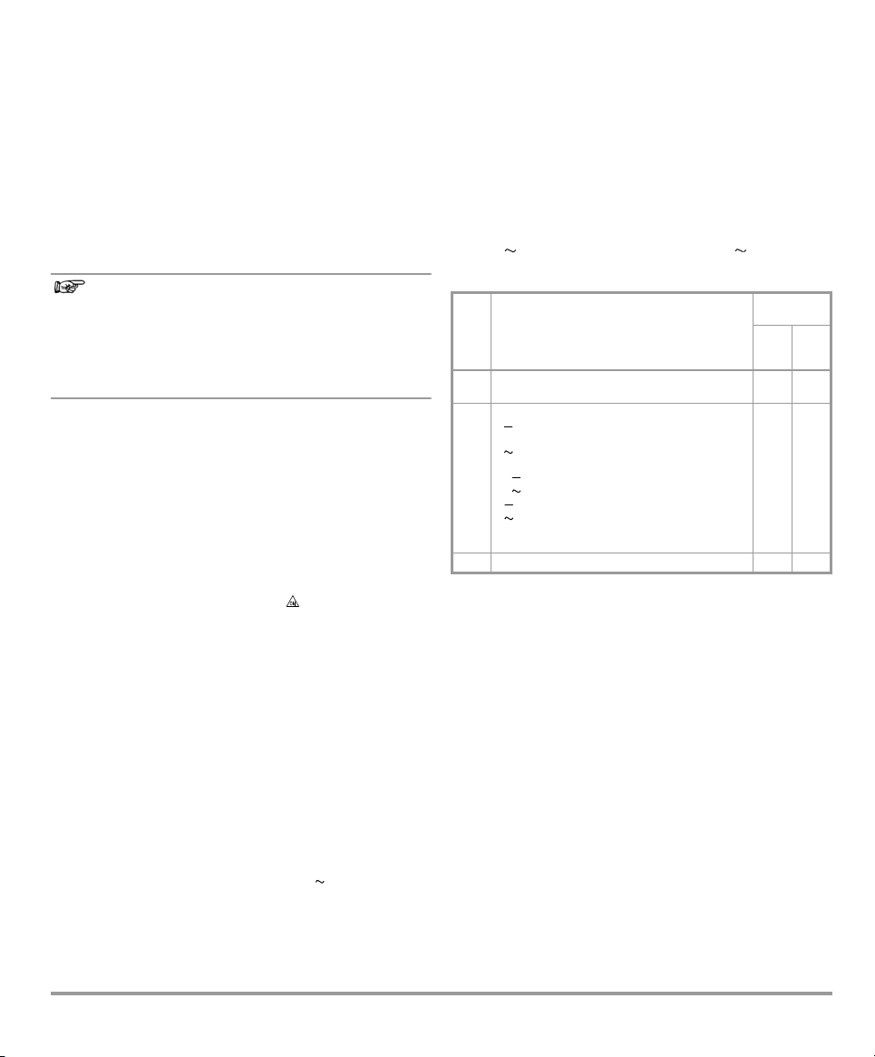
Measuring Categories and their Meaning per IEC 61010-1
CAT Definition
Measurements in electrical circuits not directly
connected to the mains system:
I
e. g. power systems in motor vehicles or
aeroplanes, batteries ...
Measurements in electrical circuits directly
II
connected to the low-voltage system:
via plug, e.g. in households, offices, laboratories ...
Measurements in facility installations:
III
stationary consumers, distributor connections,
devices attached to a distributor
Measurements at the source of low-voltage
installations:
IV
Meters, main terminal, primary overcurrent
protection devices
The measurement category and the relevant maximum rated
voltage (e. g. 1000 V CAT III) which are shown on the
instrument casing apply to your measuring instrument.
Meanings of symbols on the instrument:
Warning concerning a source of danger
(attention: observe documentation)
Earth terminal
Continuous, doubled or reinforced
insulation
This device may not be disposed of with the
trash. Further information regarding the WEEE
mark can be accessed on the Internet at
www.gossenmetrawatt.com by entering the
search term ’WEEE’.
Indicates EC conformity
CAT III / IV
Repair, Parts Replacement and Balancing
When the instrument is opened, voltage conducting parts
may be exposed. The instrument must be disconnected from
the measuring circuit before the performance of repairs, the
replacement of parts or balancing. If balancing, maintenance
or repair of a live open instrument is required, this may only
be carried out by trained personnel who are familiar with the
dangers involved.
Defects and Extraordinary Strains
If it may be assumed that the instrument can no longer be
operated safely, it must be removed from service and
secured against unintentional use.
Safe operation can no longer be relied upon:
• If the device demonstrates visible damage
• If the instrument no longer functions
• After lengthy periods of storage under unfavorable
Maximum allowable voltage
connector jacks and earth is
600 V category IV
DAkkS Calibration Upon Request:
conditions (e.g. humidity, dust, temperature), see
ambient conditions on page 16
between the
1000 V, category III or
.
4 GMC-I Messtechnik GmbH
2 Initial Start-Up
Note!
Battery
Your instrument is supplied with two 1,5 V AA size batteries in
accordance with IEC LR 6, and is ready for operation. Be sure
to refer to chapter 15.1 “Battery”, before initial start-up, or after
your device has been in storage for a lengthy period of time.
Switching the Instrument On
➭ Press the ON / OFF key.
Power-up is acknowledged with an acoustic signal. All of
the segments at the liquid crystal display (LCD) are
illuminated shortly. The LCD is shown in the diagram on
page 2.
Electrical discharge and high frequency interference
may cause incorrect displays to appear, and may
disable the measuring sequence. In such cases,
switch the instrument off and back on again in order
to reset. If the problem persists, briefly dislodge the
battery from the connector contacts.
Disconnect the instrument from the measuring circuit before
opening and refer to chapter 15 “Maintenance”!
Automatic Shutdown
The instrument switches itself off automatically if neither one
of the keys nor the rotary selector switch are activated for a
period of approximately 15 minutes.
Disabling Automatic Shutdown
The instrument can be set to continuous duty. Press the
FUNC key and the ON / OFF key simultaneously when
switching the instrument on to this end. Continuous duty is
indicated at the LCD by means of the symbol.
Switching the Instrument Off
Press the ON / OFF key.
3 Selecting Measuring Functions and Measuring Ranges
The function selector switch is linked to the automatic socket
blocking mechanism, which only allows access to two
connector jacks for each function. Be certain to remove the
appropriate plug from its respective jack before switching to
and from the “mA” or the “A” function. The socket blocking
mechanism prevents the user from inadvertently turning the
selector switch to impermissible functions after the
measurement cables have been plugged in to the instrument.
3.1 Automatic Measuring Range Selection
The multimeter is equipped with automatic measuring range
selection for all ranges except the 600 mV range. Autoranging is active as soon as the instrument is switched on.
The instrument automatically selects the measuring range
which allows for highest possible resolution of the applied
quantity.
The instrument is automatically switched to:
– The next highest range at typically (6039 digits + 1 digit)
– The next lowest range at typically (560 digits – 1 digit)
3.2 Manual Measuring Range Selection
Auto-ranging can be deactivated and measuring ranges can
be selected manually in accordance with the following table.
Manual operation is deactivated by pressing and holding the
MAN / AUTO key (approx. 1 s), by activating the
rotary selector switch, or by switching the instrument off and
then back on again.
If the instrument is switched back to auto-ranging in the
600 mV range, the respective range or 6 V is selected
automatically.
AUTO/
MAN
(4)
brief
V : 600 mV 6V 60 V 600 V 1000 V
600 mV...
V : 6V 60 V 600 V 600 mV 6V
1000 V...
mA : 60 mA 600 mA ...
brief
mA : 60 mA 600 mA ...
A : 6A 10 A 6A ...
A : 6A 10A 6 A ...
:60M 600 6k60 k
600 k 6M 60 M ...
long Return to automatic range selection — 2 x
Function
Manual mode active:
utilized measuring range is fixed
Range switching sequence for:
Acknowledge-
ment
Acou-
Dis-
stic
play
Signal
MAN
1 x
(10)
MAN
1 x
(10)
3.3 Quick Measurements
Measurements performed using a suitable fixed measuring
range are executed more quickly than those which utilize
automatic range selection. Quick measurement is made
possible with the following two functions:
• Manual measuring range selection, i.e. selection of the
measuring range with best resolution (see chapter 3.2)
or
•With the HOLD function (see chapter 5). In this way, the
correct measuring range is selected automatically after
the first measurement and all further measurements are
executed more quickly.
The selected measuring range remains active for the
subsequent series of measurements with these two
functions.
GMC-I Messtechnik GmbH 5
3.4 Relative Measurement REL
Note!
MAX MIN
MAN / AUTO *
HOLDHOLD x 2
HOLD long
A reference value for relative measurements can be stored to
memory with the keys MAN / AUTO and HOLD.
The applicable reference or correction value is substracted
individually for the respective measuring function as an offset
from all subsequent measurements, and remains in memory
until deleted, or until the multimeter is switched off.
Reference value setting is only possible for the respective
manually selected measuring range.
Setting the Reference Value
➭ Plug the measuring cable into the instrument and
measure a reference value.
➭ Press the MAN / AUTO key and the HOLD key
simultaneously.
The instrument acknowledges storage of the reference
value with an acoustic signal, and the REL symbol
appears at the LCD. The value measured at the
moment the keys are pressed serves as a reference
value.
➭ The reference value can be cleared by once again
pressing the MAN / AUTO and HOLD keys.
4.3 Display Illumination
After the instrument has been switched on, background
illumination can be activated by briefly pressing the
ON / OFF LIGHT key. Illumination is switched back off by once
again pressing the same key, or automatically after
approximately 1 minute.
5 Measured Value Memory “HOLD”
By pressing the HOLD key, the currently displayed
measurement value can be “frozen” in the display, and “Hold”
is simultaneously indicated. Automatic shutdown is
deactivated during this process.
The Hold display is deactivated if:
•the HOLD key is pressed and held
•the rotary selector switch is activated
•the FUNC multifunction key is pressed for a change of
function, e.g. AC
Hz.
6 Saving Minimum or Maximum Values
“MIN/MAX” Hold
Minimum and maximum measured values applied to the
measuring instrument’s input after the MAX/MIN function has
been activated, can be “frozen” at the display with the MAX/
Relative measurement effects the digital display only.
Relative measurement is not active during overflow.
In the case of relative measurement, quantities may
MIN function. The most important use of this function is the
determination of minimum or maximum values during longterm measured quantity observation.
also appear as negative values.
➭ Select the measurement function with the
4LCD
4.1 Digital Display
The measured value with decimal and plus or minus sign
appears at the digital display. The selected unit of measure
and the current type are displayed as well. A minus sign
appears to the left of the value during the measurement of
zero-frequency quantities, if the plus pole of the measured
quantity is applied to the “” input. “OL” is displayed if the
upper range limit of 6039 is exceeded (or 1999 in the
range).
The digital display is refreshed twice per second during V, A
and measurements.
4.2 Analog Display
The analog display with simulated pointer and the same
dynamic performance as a moving-coil mechanism is
rotary selector switch and, if appropriate, with the FUNC
multifunction key.
➭ Connect the device under test as described in the
following measurement instructions.
➭ Press the HOLD key twice.
MAX is displayed. The measuring instrument continually
updates and digitally displays the largest occurring
measured value.
➭ Press the HOLD key.
MIN is displayed. The measuring instrument continually
updates and digitally displays the lowest occurring
measured value. Pressing HOLD once more switches this
function back to MAX.
➭ Press and hold the HOLD key for approx. 2 seconds, to
quit the HOLD function.
refreshed 20 times per second during V, A and
measurements. This display is especially advantageous for
observing measured value fluctuation, and for balancing
procedures.
The analog display has its own polarity indicator. If the
measured value exceeds the display range, polarity at the
analog display is switched after approximately 0.7 seconds.
Overranging is indicated by the triangle at the right (> 6039
digits).
* range selection is not provided for with MAN + MIN / MAX
6 GMC-I Messtechnik GmbH

7 Voltage Measurement
Note!
Attention!
!
MAN
AUTO
brief
V=
– (+)
+ (–)
max. 1000 V
V=: 600 mV 1000 V
Measuring Ranges:
!
>60V:
> 1000 V:
20.00
V
DC
acoustic signal
6V 60 V
60 V 600 V
600 V 1000 V
600 mV 6V
1000 V 600 mV
MAN
AUTO
brief
V~
Max. 1000 V (2 kHz)
V~: 600 mV 1000 V
(30 Hz 2kHz)
Measuring Ranges:
~
!
> 1000 V:
* manual only
>40V:
acoustic signal
6V 60 V
60 V 600 V
600 V 1000 V
600 mV* 6V
1000 V 600 mV*
20.00
V
~
AC
TRMS
➭ Depending upon the voltage to be measured, set the
rotary selector switch to V
➭ Connect the measurement cables as shown. The “”
connector jack should be grounded.
The 600 mV measuring range can only be selected
manually with the MAN / AUTO key.
If the measured value exceeds 60 V DC or 40 V AC
the symbol appears at the display.
An intermittent acoustic signal warns the operator if
the measured value exceeds the upper range limit
value of 1000 V in the 1000 V range.
Make sure than none of the current measuring ranges
(neither “mA” nor “A”) are activated when connecting
the multimeter for the performance of voltage
measurements! If fuse trip limits are exceeded as a
result of operator error, both the operator and the
instrument are in danger!
or V .
Zero Balancing REL in the V AC und V DC Measuring Range
You can select the reference point in the V AC and V DC
measuring range:
➭ Plug the measuring cables into the instrument and
connect the free ends to each other.
➭ After selecting the measuring range, briefly press the two
HOLD and MAN / AUTO keys.
The instrument acknowledges zero balancing with an
acoustic signal and „0“ ( 1digit) and REL appears at the
LCD, depending on the measuring range. The voltage
displayed at the moment the key is pressed is automatically
substracted from all subsequent measured values.
Zero balancing can be deleted:
– by briefly pressing the MAN / AUTO key, which is
acknowledged with an acoustic signal,
– by switching the instrument off.
GMC-I Messtechnik GmbH 7
7.1 Sub-function Hz
➭ Turn t h e rotary selector switch to V
➭ Briefly press the FUNC multifunction key to display the
frequency (max. 2_kHz) of the AC voltage.
➭ Press the FUNC key once again to quit the Hz function.

8 Current Measurement
FUNC
brief
1x
A
...6 A
!
00.00
A
Current
~ ~
1
3
2
A: 6A 10.00 A
Measuring Range:
MM
>11A:
!
0.000
A
acoustic signal
acoustic
signal
...10 A
DC AC~
AC ~ DC
DC
AC ~
TRMS
DC
AC ~
TRMS
➭ First disconnect supply power from the measuring circuit
or the consuming device, and discharge any included
capacitors.
➭ Select the A range with the rotary selector switch for
current greater than 600 mA, or the mA range for
current less than 600 mA. Activate the highest measuring
range first when measuring current of an unknown
magnitude.
➭ Select the current type appropriate for the measured
quantity by briefly pressing the FUNC key. Each time the
key is pressed, DC and AC are alternately selected, and
switching is acknowledged with an acoustic signal. The
selected current type is indicated at the LCD by means of
the DC and AC symbols.
DC current is always active immediately after range
selection with the rotary selector switch.
➭ Securely connect the measuring instrument to the
consuming device in series as shown (without transfer
resistor).
8 GMC-I Messtechnik GmbH

connector jacks.The following symbol appears at the
FUNC
brief
Measuring Range:
mA
... 600 mA
000.0
mA
~
R
x
~
R
x
1
3
2
> 600 mA:
!
Current
DC AC~
AC ~ DC
1x
mA: 60 mA 600,0 mA
00.00
mA
... 60 mA
acoustic signal
acoustic
signal
DC
AC ~
TRMS
DC
AC ~
TRMS
digital display in this case: .
• If a fuse blows, eliminate the cause of overload before
placing the instrument back into service!
• Refer to chapter 15 “Maintenance”, regarding fuse
replacement.
Zero Balancing REL during Current Measurement
You can select the reference point in the mA AC / DC and
A AC / DC measuring range:
➭ Plug the measuring cables into the instrument and
connect the free ends to each other.
➭ After selecting the measuring range, briefly press the two
HOLD and MAN / AUTO keys.
The instrument acknowledges zero balancing with an
acoustic signal and „0“ ( 1digit) and REL appears at the
LCD, depending on the measuring range. The voltage
displayed at the moment the key is pressed is automatically
substracted from all subsequent measured values.
Zero balancing can be deleted:
– by briefly pressing the MAN / AUTO key, which is
acknowledged with an acoustic signal,
– by switching the instrument off.
Notes Regarding Current Measurement:
• The measuring circuit must be mechanically stable and
must be secured against accidental interruption. Select
conductor cross-sections and connectors such that no
overheating occurs.
• An intermittent acoustic signal warns the operator if the
measured value exceeds the upper range limit in the
600 mA and 10 A measuring ranges.
• Measuring ranges up to 600 mA are protected against
short-circuit current of up to 25 A with an FF 1.6 / 1000 V
fuse link in combination with power diodes. The fuse has
a breaking capacity of 10 kA at a nominal voltage of
1000 V and ohmic load.
• The 6A and 10 A current measuring ranges are protected
with a 10 A / 1000 V fuse link. The fuse has a breaking
capacity of 30 kA at a nominal voltage of 1000 V and
ohmic load.
• If one of the fuses blows, this condition is indicated at the
LCD as soon as a measured quantity with a voltage of
greater than 4 V is applied to the corresponding
GMC-I Messtechnik GmbH 9

8.1 Measuring Alternating Current with (Clip-On) Current
Attention!
!
~
R
x
~
R
x
1
3
Current
V~
05.00
V
Z13B
2
0.5
k
R
x
: 600 40 M
Measuring Range:
+–
R
x
0V !
!
Tra nsf orme rs
8.1.1 Transformer Output mA / A
If current transformers are operated without being
connected at the secondary side (e.g. as a result of
defective or missing cables, a blown device fuse or
incorrect connection), dangerously high voltages
may occur at the connector jacks. For this reason,
make sure that the measuring instrument’s current
path and the transformer’s secondary coil connected
to the instrument constitute an uninterrupted circuit,
and connect this circuit to the and mA or A jacks.
Maximum allowable operating voltage is equal to the current
transformer’s nominal voltage. Do not forget to consider the
transformer’s transformation ratio and additional display error
when reading measured values.
8.1.2 Transformer Output V
Some transformers are equipped with a voltage output
(designation mV/A). The secondary terminals must thus be
connected to and V.
9 Resistance Measurement
➭ Make sure that the device under test is voltage-free.
Interference voltages distort measurement results!
➭ Set the rotary selector switch to .
➭ Connect the device under test as shown.
Zero Balancing REL in the entire resistance measuring range
Cable and contact resistances can be eliminated during
resistance measurement by means of zero balancing:
➭ Plug the measuring cables into the instrument and
connect the free ends to each other.
➭ Press the MAN / AUTO and HOLD keys after selecting the
measuring range.
The instrument acknowledges zero balancing with an
acoustic signal and „0“ (+1 digit) and REL appears at
the LCD, depending on the measuring range. The
resistance value measured at the moment the key is
pressed is automatically subtracted from all subsequent
measured values.
Zero balancing can be deleted:
– by briefly pressing the MAN / AUTO key, which is
acknowledged by an acoustic signal,
– by switching the instrument off.
10 GMC-I Messtechnik GmbH

10 Continuity and Diode Testing
Note!
0.654
0L
Conducting Direction
Reverse Direction
0.000
V
FUNC
brief
0V !
Continuity
R < 40
!
030.0
acoustic
signal
➭ Make sure that the device under test is voltage-free.
Interference voltages distort measurement results!
➭ Set the rotary selector switch to .
➭ Connect the device under test as shown.
Conducting Direction and/or Short-Circuit:
The instrument displays conducting-state voltage in volts. As
long as voltage drop does not exceed the maximum display
value of 1,999 V, several series connected components or
reference diodes can be tested with a small reference
voltage.
Reverse Direction or Interruption:
The measuring instrument indicates overflow “OL”.
Resistors and semiconductors which are connected
in parallel to the diode distort measurement results!
Sub-function Continuity Test with Acoustic Signal
If the sub-function “continuity test with acoustic signal” is
activated, a continuous acoustic signal is generated by the
instrument within a display range of R < 40.
Acoustic Signal ON:
➭ Briefly press the FUNC key.
Activation is acknowledged with an acoustic signal.
The symbol appears at the display as well.
Acoustic Signal OFF:
➭ Briefly press the FUNC key once again.
Deactivation is acknowledged with an acoustic signal.
The symbol is cleared from the display.
The acoustic signal function is always inactive immediately
after the “continuity test” function has been selected with the
rotary selector switch. The acoustic signal can be activated
and deactivated by repeatedly and briefly pressing the FUNC
key. If the key is pressed and held, the acoustic signal is
always deactivated, which is acknowledged with two
acoustic signals.
GMC-I Messtechnik GmbH 11

11 Capacitance Measurement
Note!
Note!
+
–
F
00.00
nF
F: 40 nF 400 μF
Messbereich:
Duty Cycle (%) = ——————— • 100
Pulse Duration
Period
➭ Make sure that the device under test is voltage-free.
Interference voltages distort measurement results!
➭ Turn the rotary switch to the “F” position.
➭ Connect the (discharged!) device under test to the and V
jacks with the measurement cables
12 Frequency Measurement – Duty Cycle Measurement
➭ Turn the rotary switch to the Hz position.
➭ Apply the measured quantity as described under voltage
measurement.
➭ Smallest measurable frequencies and maximum
allowable voltages are listed in chapter 14 “Characteristic
Values”.
The “–“ pole of polarized capacitors must be
connected to the „“ jack.
Resistors and semiconductor paths connected in
parallel to the capacitor distort measurement results!
12.1 Duty Cycle Measurement
The pulse-period ratio can be ascertained for square-wave
signals with the duty cycle measurement.
➭ Turn the rotary swith to Hz position
➭ Briefly press the multifunction FUNC key twice. The
instrument is switched to duty cycle measurement. The
duty cycle, i.e. the pulse duration of a signal as a
percentage, is displayed at the LCD.
The applied frequency must remain constant during
duty cycle measurement.
12.2 RPM Measurement
RPM is measured by acquiring pulses. The number of
measurable pulses per revolution varies depending upon the
type of engine.
➭ Set the rotary switch to Hz.
➭ Press the multifunction key FUNC twice until unit of
measure RPM appears.
The measured value then appears, for
example
“244.3 RPM”.
12 GMC-I Messtechnik GmbH

13 Temperature Measurement
Note!
023.2
C
TC Measuring Range
Type_K –50 +400 C
+401 ... +800C
C
FUNC
brief
TYPE K
C F
The multimeter provides for the measurement of
temperatures within a range of – 50°C to + 800°C with the
help of a type K temperature sensor.
➭ Set the rotary selector switch to „°C“.
➭ Connect the sensor to the two accessible jacks.
The device indicates the measured temperature in C at
the digital display.
➭ Briefly press the FUNC key to switch between C and F.
The cold junction temperature (reference
temperature) is measured with a Pt100 temperature
sensor inside the instrument. It is displayed when the
measuring input is short-circuited. Due to internal
heating or a change from warm to cold environment
or vice versa, the reference temperature may differ
from the ambient temperature.
GMC-I Messtechnik GmbH 13

14 Characteristic Values
Meas.
FunctionMeasuring Range
Resolution
Input Impedance
6000
600 mV 100 V10M // < 40 pF 8.1 M // 50 pF 0.5 + 5
6V 1mV5.2M // < 40 pF 4.6 M // 50 pF 0.5 + 5
V
60 V 10 mV 5 M // < 40 pF 4.4 M // 50 pF 0.5 + 5
600 V 100 mV 5 M // < 40 pF 4.4 M // 50 pF 0.5 + 5
1000 V 1 V 5 M // < 40 pF 4.4 M // 50 pF 0.5 + 5
Voltage drop at approx. range limit
60 mA 10 A 100 mV 100 mV
A
600 mA 100 A 700 mV 700 mV
6 A 1 mA 200 mV 200 mV
10 A 10 mA 300 mV 300 mV
Open-circuit
voltage
Meas. current at
range limit
600 100 m max. 1 V max. 250 A1 + 5
6k 1 max. 1 V max. 100 A 0.7 + 3
60 k 10 max. 1 V max. 12 A 0.7 + 3
600 k 100 max. 1 V max. 1,2 A 0.7 + 3
6M 1k max. 1 V max. 120 nA 0.7 + 3
40 M 10 k max. 1 V max. 50 nA 2.0 + 3
2V 1mV max. 3V 1.0 + 5
600 0.1 max. 1 V max. 250 A 1.0 +5
-50,0 ...
TYP K
C
+400 C
+ 401 ...
+800 C
0,1 C 1.0 + 5 K
0,1 C 5.0 + 7 K
Power limit (... % rdg. + ... d)
Hz
V
Hz
100 Hz 0,1 Hz
1000 Hz 1 Hz
100 Hz 0,1 Hz
1000 Hz 1 Hz
6
V x Hz @ U > 100 V 0.1 + 2
3 x 10
6
3 x 10
V x Hz @ U > 100 V
1000 kHz 1 kHz
Power limit
30 Hz ... 1KHz: 2,0 ... 98,0
1 kHz ... 4 kHz: 5,0 ... 95,0 0.2% v.MUL/kHz + 8 D
%
6
3 x 10
V x Hz @ U > 100 V
40 kHz ... 10 kHz:10,0 ...90,0 0.2% v.MUL + 8 D
Intrinsic Uncertainty at Max. Resolution
under Reference Conditions
(... % rdg. + ... d) (... % rdg. + ... d)
1.0 + 5 (> 10 D) 1.5 + 5 (> 10 D)
(... % rdg. + ... d)
(... % rdg. + ... K)
2)
3)
3)
0.1 + 2
0.2% v.MUL + 8 D
1 + 5
Overload Capacity
1)
5)
5)
Value Time
1000 V
DC
AC
eff
Sinus
Cont.
Meas.
Function
V
1.0 A Cont.
10 A
1000 V
DC
AC
eff
Sinus
1000 V
DC/AC
eff
Sinus
1000 V
1000 V
1000 V
4)
Cont.
max. 10 s
max. 10 s
max. 10 s
max. 10 s
max. 10 s
A
C
Hz
V
Hz
%
Rpm
60 ... 99.99 k 1 Rpm 2 Rpm
1000 V
max. 10 s
Rpm
Discharge Resistance (... % rdg. + ... MR)
40 nF 10 pF 10 M 2.0 + 10 with zero active
400 nF 100 pF 1 M 1.0 + 6
F
4 μF 1 nF 100 M 1.0 + 6
40 μF 10 nF 12 M 2.5 + 6
1000 D
DC
AC
max. 10 s
F
400 μF 100 nF 3 M 5.0 + 6
1)
At 0 C ... + 40 C
2)
with zero balancing, + 35 digits without zero balancing
3)
without sensor
4)
12 A 5 minutes, 16 A 30 seconds
5)
1 ... 35 d from the zero point due to TRMS converter when probe tips are shortcircuited
Key
rdg. = reading (measured value); d = digit
MUL = upper range limit; MR = measuring range
14 GMC-I Messtechnik GmbH

Influencing Quantities and Influence Error
Influencing
Temperature
Measured
Frequency
Influencing
MIN / MAX — V , A 2Digits
1)
2) With zero balancing
3) After the symbol appears at the display
Sphere of Influence
Quantity
0 C ... +21 C
and
+25 C... +40 C
> 30 Hz ... 45 Hz A 2.0 + 10
> 65 Hz ... 1 kHz
Quantity
Quantity
Battery
Volta ge
Relative
Humidity
For temperature: specified error valid starting with t emperature changes as of 10 K.
For frequency: specified error valid starting with display values as of 300 digits.
> 30 Hz ... 45 Hz
> 65 Hz ... 500 Hz 600 mV 35 + 20
>65Hz...800Hz
Sphere of
Influence
3)
... < 2.9 V
> 3.1 V ... 3.6 V
75%
3 days
Instrument off
HOLD — 1Digits
Measured Quantity /
Measuring Range
600 mV 1.0 + 3
6 ... 600 V 0.15 + 1
1000 V 0.2 + 1
V0.4+2
2)
0
2)
600
6k ... 6 M 0.15 + 1
40 M 1.0 + 1
mADC, ADC 0.5 + 1
mAAC, AAC 0.75 + 1
– 50 ... + 200 C 0.5 K + 2
+ 200 ... + 400 C 0.5 + 2
60 / 600 mA / 6 A 1.5 + 10
10 A 2 + 10
600 mV 3 + 10
6 / 60 /600 V 2.5 + 10
1000 V 3.5 + 20
6 / 60 V 2.5 + 10
600 V 3 + 20
1000 V 3.5 + 20
Measured Quantity /
Measuring Range
V 2Digits
V 4Digits
A 4Digits
A 6Digits
60 / 600 / C 4Digits
6k ... 40 M3Digits
V
A
C
Influence Error 1)
(... % rdg. + ... digits)
0.15 + 2
0.25 + 2
Influence Error
1 x intrinsic uncertainty
Influencing
Quantity
Common
Mode
Interference
Volt age
Series Mode
Interference
Volt age
Sphere of Influence
Interference quantity max. 600 V V > 120 dB
Interference quantity max. 600 V
50 Hz, 60 Hz sine
Interference quantity: V ,
respective nominal value
of the measuring range,
max. 600 V , 50 Hz, 60 Hz sine
Interference quantity max. 600 V V > 110 dB
Measuring
Range
6V ,
60 V
600 V > 70 dB
V > 50 dB
Crestfaktor CF
Test signal: Rectangle 55 Hz, no DC component
Influencing
Quantity
Crest factor CF
Sphere of Influence
1.5 < CF 2
2 < CF 4 5% rdg.
Measured Quantity /
Measuring Range
6 V, 60 V, 600 V,
1000 V
The admissible crest factor CF of the alternating quantity to
be measured depends on the display value.
Crest factor 4 at the end of range, it is increased accordingly
when the range is reduced. However, due to input protection,
voltage is limited to 1000 V, therefore the admisible crest factor in the 600 V ranges is half as high.
When the waveform is unknown, measurement is to be performed with manual range selection in the case of higher frequency signals.
Power limiting: voltage x frequency max. 3 x 10
6
Response Time (after manual range selection)
Measured
Quantity/
Measuring Range
V , V ,
A , A
600... 6 M 1.5 s 2 s
40 M 4 s 5 s
C—*max. 3 s
F—*max. 5
* without bargraph
Response Time
Analog Display Digital Display
0.7 s 1.5 s
— * 1.5 s
— * < 50 ms
Measured Quantity
Step Function
from 0 to 80%
of the upper range limit
from to 50%
of the upper range limit
from 0 to 50%
of the upper range limit
Damping
>80dB
Influence Error
1% rdg.
V x Hz.
GMC-I Messtechnik GmbH 15

Reference Conditions
Ambient temperature + 23 C 2K
Relative humidity 40 % ... 60 %
Measured quantity
frequency 45 Hz ... 65 Hz
Measured quantity
waveshape sinusoidal
Battery voltage 3 V 0.1 V
Display
LCD panel (65 mm x 30 mm) with analog and digital display
including unit of measure, type of current and various special
functions
Analog
:
Display LCD scale with pointer
Scale length 55 mm in all ranges
Scaling 0 ... 60 with 61 scale divisions in
all ranges
Polarity display With automatic switching
Overflow display Triangle
Measuring rate 30 measurements per second
Digital
:
Display / char. height 7-segment characters / 15 mm
Number of places 3
6
/7-place 6000 steps
Overflow display “OL” appears
Polarity display “–” sign is displayed if plus pole is
connected to “”
Measuring rate 3 measurements per second
Power Supply
Battery 2 x 1.5 V AA size batteries
alkaline manganese per IEC LR6 or
equivalent rechargeable NiCd
battery
Service life With alkaline manganese:
approx. 750 hours for V , A
approx. 200 hours for V , A
Battery test is displayed automatically if
battery voltage drops to below
approx. 2.1 V.
Electrical Safety
Safety class II per IEC 61 010-1:2010/
DIN EN 61010-1:2011/
VDE 0411-1:2011
Overvoltage category 1000 V CAT III, 600 V CAT IV
Nominal voltage 1000 V
Fouling factor 2
Test voltage 6.7 kV~ per IEC 61010-1:2010/
DIN EN 61010-1:2011
Electromagnetic Compatibility (EMC)
Interference emission EN 61 326-1: 2013 class B
Interference immunity
EN 61326-1: 2013
EN 61326-2-1: 2013
Fuses
Fuse links for all
ranges up to 600 mA FF(UR) 1.6 A/1000 V;
mm,
6.3 mmx32
switching capacity: 10 kA at
1000 V~ with ohmic load, protects
all current measuring ranges up to
600 mA in combination with power
diodes
Fuse links for all
ranges up to 10 A FF(UR) 10 A/1000 V;
10 mmx 38 mm,
switching capacity: 30 kA at
1000 V with ohmic load, protects
6 A and 10 A ranges to 600 V
Refer to chapter 15
“Maintenance”, regarding fuse
manufacturers and types.
Ambient Conditions
Accuracy range 0 C ... + 40 C
Operating temperature –10 C ... + 50 C
Storage temperature – 25 C ... + 70 C without batteries
Relative humidity
45 ... 75%, no condensation allowed
Elevation to 2000 m
Deployment indoors only, except within
specified ambient conditions
Mechanical Design
Protection IP 40
(IP 54 special type WORLD_IS)
per DIN VDE 0470 part 1 /
EN 60529
Extract from table on the meaning of IP codes
IP XY
st
(1
Protection against
digit X)
foreign object entry
0 not protected 0 not protected
1 50.0 mm dia. 1 vertically falling drops
2 12.5 mm dia. 2
3 2.5 mm dia. 3 spraying water
4 1.0 mm dia. 4 splashing water
IP XY
(2nd digit Y)
Protection against the
penetration of water
vertically falling drops
with enclosure tilted 15
Dimensions 84 mm x 195 mm x 35 mm
Weight approx. 350 gr. with battery
16 GMC-I Messtechnik GmbH

15 Maintenance
Attention!
!
Attention!
!
(b) (a)
Disconnect the instrument from the measuring circuit
before opening to replace batteries or fuses!
15.1 Battery
Make sure that no battery leakage has occurred before initial
start-up, and after long periods of storage. Continue to
inspect the batteries for leakage at short, regular intervals.
If battery leakage has occurred, carefully and completely
clean the electrolyte from the instrument with a damp cloth,
and replace the batteries before using the instrument.
If the symbol appears at the display , the batteries should
be replaced as soon as possible. You can continue working
with the instrument, but reduced measuring accuracy may
result.
The instrument requires 2 x 1.5 V AA size batteries or two
equivalent NiCd rechargeable batteries.
Replacing the Battery
➭ Set the instrument face down onto a flat working surface,
loosen the two screws at the back and lift off the housing
base, starting at the bottom. The housing top and
housing base are held together with the help of snap
hooks at the top front.
➭ Remove the batteries from the battery compartment.
➭ Insert two new 1.5 V AA size batteries into the battery
compartment, making sure that the plus and minus poles
match up with the provided polarity symbols.
➭ Important for reassembly: First set the housing base onto
the housing top and align accurately (see photo below).
Then press the two housing halves together, first at the
bottom front (a), and then at the top front (b).
➭ Secure the housing base with the two screws.
➭ Please dispose of depleted batteries in accordance with
environmental protection regulations!
15.2 Fuses
If one of the fuses blows, this condition is displayed at the
LCD as soon as a measured quantity with a voltage of greater
than 4 V is applied to the corresponding connector jacks. The
following symbol appears at the digital display in this case:
.
The 16 A fuse interrupts the 6 A and 10 A ranges, and the
1.6 A fuse interrupts all other current measuring ranges. All
other measuring ranges remain functional.
If a fuse should blow, eliminate the cause of overload before
placing the instrument back into service!
Replacing the Fuse
➭ Open the instrument as described under “Replacing the
Battery”.
➭ Remove the blown fuse with the help of an object such
as a test probe, and replace it with a new fuse.
The following fuses are approved for use:
– For current measuring ranges up to 600 mA:
Type FF 1.6 A / 1000 V AC (10 kA),
6.3 mm x 32 mm
– For 6 A and 10 A current measuring ranges:
FF 10 A/1000 V AC (30 kA),
10 mm x 38 mm
Use specified fuses only! If fuses with other blowing
characteristics, other current ratings or other
breaking capacities are used, the operator is placed
in danger, and protective diodes, resistors and other
components may be damaged.
The use of repaired fuses or short-circuiting the fuse holder is
prohibited.
15.3 Housing
No special maintenance is required for the housing. Keep
outside surfaces clean. Use a slightly dampened cloth for
cleaning. Avoid the use of cleansers, abrasives and solvents.
Device Return and Environmentally Compatible Disposal
The instrument is a category 9 product (monitoring and control
instrument) in accordance with ElektroG (German Electrical
and Electronic Device Law). This device is subject to the
RoHS directive. Further-more, we make reference to the fact
that the current status in this regard can be accessed on the
Internet at www.gossenmetrawatt.com by entering the
search term WEEE.
We identify our electrical and electronic devices in
accordance with WEEE 2012/19/EU and ElektroG
with the symbol shown to the right per DIN EN
50419.
GMC-I Messtechnik GmbH 17

These devices may not be disposed of with the trash. Please
Attention!
!
Pb Cd Hg
contact our service department regarding the return of old
devices.
If you use batteries or rechargeable batteries in your instrument
or accessories which no longer function properly, they must
be duly disposed of in compliance with the applicable
national regulations.
Batteries or rechargeable batteries may contain harmful
substances or heavy metal such as lead (PB), cadmium (CD)
or mercury (Hg).
They symbol shown to the right indicates that
batteries or rechargeable batteries may not be
disposed of with the trash, but must be delivered to
collection points specially provided for this purpose.
16 Recalibration
The respective measuring task and the stress to which your
measuring instrument is subjected affect the ageing of the
components and may result in deviations from the
guaranteed accuracy.
If high measuring accuracy is required and the instrument is
frequently used in field applications, combined with transport
stress and great temperature fluctuations, we recommend a
relatively short calibration interval of 1 year. If your measuring
instrument is mainly used in the laboratory and indoors
without being exposed to any major climatic or mechanical
stress, a calibration interval of 2-3 years is usually sufficient.
17 Accessories
17.1 General
The extensive accessories available for our measuring
instruments are checked for compliance with currently valid
safety regulations at regular intervals, and are expanded as
required for new applications. Currently up-to-date
accessories which are suitable for your measuring instrument
are listed at the following web address along with photo,
order number, description and, depending upon the scope of
the respective accessory, data sheet and operating
instructions: www.gossenmetrawatt.de
(Products Measuring Technology – Portable Multimeter
Accessories )
or
(Products Measuring Technology – Portable Digital
Multimeters METRA HIT ... Accessories).
17.2 Technical Data for Measurement Cables (included: KS17-2 safety cable set)
Electrical Safety
Maximum Rated Voltage 600 V
Measuring Category
CAT IV CAT II I CAT II
Maximum Rated Current 1 A 1 A 16 A
with safety cap applied —
without safety cap applied — —
1000 V
1000 V
During recalibration* in an accredited calibration laboratory
(DIN EN ISO/IEC 17025) the deviations of your instrument in
relation to traceable standards are measured and
documented. The deviations determined in the process are
used for correction of the readings during subsequent
Ambient Conditions (EN 61010-031)
Temperature –20C ... + 50C
Relative humidity max. 80%
Pollution degree 2
application.
We are pleased to perform DAkkS or factory calibrations for
Application KS17-2
you in our calibration laboratory. Please visit our website at
www.gossenmetrawatt.com ( Company DAkkS
Calibration Center or FAQs Calibration questions and
answers).
By having your measuring instrument calibrated regularly, you
fulfill the requirements of a quality management system per
DIN EN ISO 9001.
Please observe the maximum values of the electrical safety
of the device.
In conformity with standard DIN EN 61010-031,
measurements in an environment according to
measuring category II I and IV may only be performed
with the safety cap applied to the test probe of the
measurement cable.
For establishing contact in 4 mm jacks you have to remove
the safety cap by levering out the snap lock of the safety cap
with another sharp object (e.g. the second test probe).
*
Verification of specifications or adjustment services are not part of the
calibration. For products from our factory, however, any necessary adjustment
is frequently performed and the observance of the relevant specification is
confirmed.
18 GMC-I Messtechnik GmbH

18 Repair and Replacement Parts Service,
Calibration Center* and Rental Instrument Service
If required please contact:
GMC-I Service GmbH
Service Center
Thomas-Mann-Str. 20
90471 Nürnberg • Germany
Phone +49 911 817718-0
Fax +49 911 817718-253
E-Mail service@gossenmetrawatt.com
www.gmci-service.com
This address is only valid in Germany.
Please contact our representatives or subsidiaries for service
in other countries.
* DAkkS Calibration Laboratory for Electrical Quantities
Competent Partner
GMC-I Messtechnik GmbH is certified in accordance with
DIN EN ISO 9001.
Our DAkkS calibration laboratory is accredited by the
Deutsche Akkreditierungsstelle GmbH (National accreditation
body for the Federal Republic of Germany) in accordance
with DIN EN ISO/IEC 17025 under registration number D-K15080-01-01.
We offer a complete range of expertise in the field of
metrology: from test reports and factory calibration certificates,
right on up to DAkkS calibration certificates.
Our spectrum of offerings is rounded out with free test
equipment management.
D-K-15080-01-01 accredited per
DIN EN ISO/IEC 17025
Accredited quantities: direct voltage, direct current value, direct
current resistance, alternating voltage, alternating current value,
alternating current active power, alternating current apparent power,
DC power, capacitance, frequency, temperature
An on-site DAkkS calibration station is part of our service
department. If errors are discovered during calibration, our
specialized personnel are capable of completing repairs using
original replacement parts.
As a full service calibration lab, we can calibrate instruments
from other manufacturers as well.
DAkkS Calibration Certificate Reprints (upon request)
If you order a DAkkS calibration certificate reprint for your
instrument, please provide us with the reference numbers
indicated in the upper and lower most fields of the calibration
seal. We do not need the instrument’s serial number.
19 Manufacturer’s Guarantee
All METRAHIT digital multimeters and calibration instruments
are guaranteed for a period of 3 years after shipment. The
manufacturer’s guarantee covers materials and
workmanship. Damages resulting from use for any other than
the intended purpose or operating errors, as well as any and
all consequential damages, are excluded.
The calibration certificate confirms that the product
conformed to the specified technical data at the time of
calibration. We guarantee the observance of the specified
technical data within the admissible tolerance limits for a
period of 12 months from delivery.
20 Product Support
If required please contact:
GMC-I Messtechnik GmbH
Hotline Produktsupport
Phone +49 911 8602-0
Fax +49 911 8602 709
E-Mail support@gossenmetrawatt.com
GMC-I Messtechnik GmbH 19

Edited in Germany • Subject to change without notice • A pdf version is available on the Internet.
GMC-I Messtechnik GmbH
Südwestpark 15
90449 Nürnberg •
Germany
Phone +49 911 8602-111
Fax +49 911 8602-777
E-Mail info@gossenmetrawatt.com
www.gossenmetrawatt.com
 Loading...