

Page 1
Operating Instructions
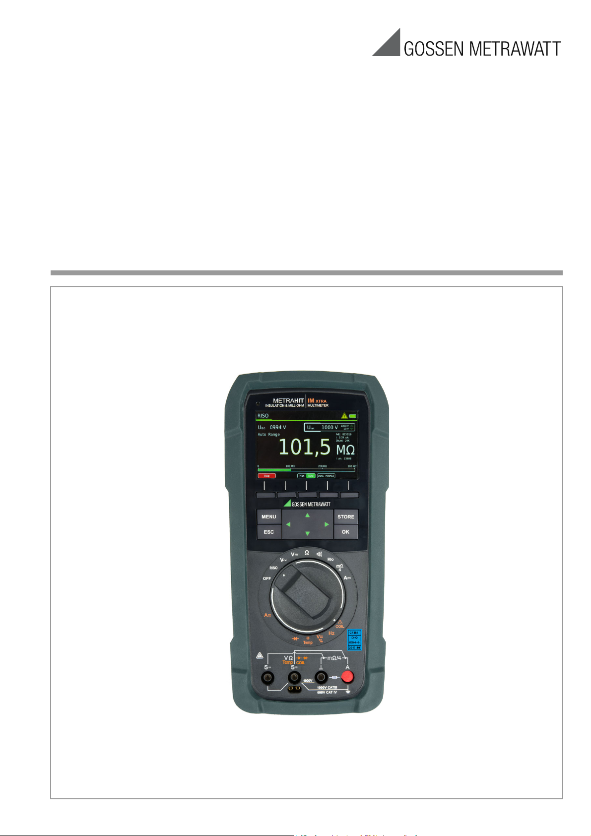
METRAHITIM XTRA
(M273A/D/W)
& METRAHITIM E-DRIVE
Insulation Tester, Milliohmmeter,
TRMS Multimeter, Short-Circuited Coil Tester
(M274A/B)
3-447-035-03
6/10.19
Page 2

Scope of Delivery (depending on instrument variant)
1kHz
1kHz
1 METRAHIT IM XTRA or METRAHIT IM E-DRIVE multimeter
with rubber holster
1 Probe with start/stop and store/send function
1 KS17-2 cable set: 1 pair of safety measurement cables,
red/black, with 4 mm test tips
1 Type KC4 Kelvin clip (1 pair with METRAHIT IM XTRA)
1 Type KC27 Kelvin probe (with METRAHIT IM E-DRIVE only)
1 Quick change, rechargeable lithium polymer battery with
micro USB charging socket
1 USB mains power pack (5 V DC, 2 A) with cable and micro
USB charging plug
1 DAkkS calibration certificate
1 Hard case for the multimeter and accessories
1 Condensed operating instructions, German/English
– Comprehensive operating instructions in German and English
available on the Internet for download at www.gossenme-
trawatt.com
1 Card with registration key
for the software
Overview Supply
Accessories Type Article No. M273S M274S
METRAHIT IM XTRA
METRAHIT IM E-DRIVE BT M274B X
LiIon module & USB charger Z270A+ X X
Mains module with electrical
isolation and USB charger O O
Remote probe Z270S Z270S X X
Cable set
1 pair Kelvin clips KC4 Z227A X O
1 pair Kelvin probes KC27 Z227B O O
1 Kelvin clip &
1 Kelvin probe KC&S Z227C — X
Hard case HC40 Z270K X X
COIL Adapter 10 μH ,,, 50 mH COIL Adapter 50mH Z270F O O
COIL Adapter 10 μH ,,, 500 mH
IZYTRONIQ Business Starter
Licence S101S & Z956A
KS17-2
COIL Adapter XTRA Z270M O O
Legend
X = Standard
O = Option
— = not possible, not provided for
M273D X
GTY362003
P0002 X X
S101S &
Z956A X X
Overview of Included Features
Function METRAHIT IM XTRA (BT)
METRAHIT IM E-DRIVE (BT)
VDC (Ri 9 M)
VAC / Hz TRMS (Ri 9 M)
V
TRMS (Ri 9 M)
AC+DC
V
TRMS (Ri 1 M)
AC+DC
R
range (interference voltage)
ISO
Hz (VAC)
V
A
Fuse
Current sensor transformation ratio
Hz (A AC)
Insulation resistance RISO: test voltages
Short-circuited coil test (1 kV) with COIL adapter
Duty cycle measurement as %
RPM measurement
Resistance Rlo with 200 mA per
EN 61557 / VDE 0413
Milliohm with 4-wire method, m with 200 mA
Milliohm with 4-wire method, m with 1 A pulse
Fuse
Resistance
Continuity
Diode ... 5.1 V
Temperature: °C/°F TC type K and Pt100/1000
Capacitance
Min-Max / data hold
Test sequence
64 MBit memory
Bluetooth® interface
WiFi interface
3.5" TFT color graphic display
Probe with start/stop and send/store keys
Quick-change battery with USB charging
Mains module with electrical isolation and USB
WPC quick change battery for inductive charging
Protection
Measuring category
1
2
bandwidth
AC, AC+DC
DC, AC, AC+DC
With optional temperature sensors
For 300,000 measured values, sampling rate adjustable from 0.1 seconds to 9 hours
/ Hz TRMS
2
1 mV : 1
50
1
METRAHIT IM XTRA BT
METRAHIT IM E-DRIVE BT
1000 V CAT III, 600 V CAT IV
✔
filter
filter
✔
... 300 kHz
100 kHz
10 nA ... 1 A
1 A / 1000 V - 30 kA
• 10 • 100 • 1000 mA
... 30 kHz
• 100 • 250 • 500 • 1000 V
Option
✔
✔
✔
✔
✔
FF 1A/1000 V – 30 kA
✔
✔
✔
✔
✔
✔
20 steps
✔
Option
✔
✔
✔
Option
Option
IP 52
Accessories (sensors, plug inserts, adapters, consumable materials)
The accessories available for your instrument are checked for
compliance with currently valid safety regulations at regular intervals, and are amended as required for new applications. Currently
up-to-date accessories which are suitable for your measuring
instrument are listed on our website along with photo, order number, description and, depending upon the scope of the respective
accessory, data sheet and operating instructions:
www.gossenmetrawatt.de
Software Version
These operating instructions describe a multimeter based on software version 1.2.6. Refer to chapter 4.4.1 in order to query the
respectively installed version number.
Current operating instructions for the latest firmware update are
available for download from our website at
www.gossenmetrawatt.com.
Please register at myGMC in order to continuously receive the latest information regarding current software and firmware, as well
as instrument updates and options.
2 GMC-I Messtechnik GmbH
Page 3

Contents Page Contents Page
1 Addresses .........................................................................4
1.1 Product Support .......................................................................... 4
1.2 Recalibration Service .................................................................. 4
1.3 Repair and Replacement Parts Service
Calibration Center* and Rental Instrument Service .................... 4
2 Safety Features and Precautions ..................................... 5
2.1 Use for Intended Purpose ...........................................................6
2.2 Meanings of Danger Symbols ..................................................... 6
2.3 Meanings of Acoustic Warning Signals ......................................6
3 Operating Overview .......................................................... 7
3.1 Connections, Keys, Rotary Switch, Symbols ..............................7
3.2 Symbols Used in the Digital Display .......................................... 7
3.3 Symbols Used for Rotary Switch Positions ................................ 8
3.4 User Interface Symbols in the Following Sections ..................... 8
3.5 Symbols on the Instrument ......................................................... 8
4 Initial Startup .................................................................... 9
4.1 Battery Pack ...............................................................................9
4.2 Mains Module ............................................................................. 9
4.3 Switching the instrument On ...................................................... 9
4.4 Querying or Setting Operating Parameters – General Setup ......9
4.4.1 Info > Version – Check Current Software Version ............................ 9
4.4.2 Language >German/English – Selecting the User Interface
Language ..................................................................................... 9
4.4.3 System > Date/Time – Setting Date and Time ................................9
4.4.4 System > Brightness – Digital Display Brightness ........................... 9
4.4.5 System > Display Zeros ............................................................... 10
4.4.6 System > Change Password ........................................................ 10
4.4.7 System > Display Profile – Digital Display View ............................. 10
4.4.8 System > Default Settings ........................................................... 11
4.5 Switching the Instrument Off .................................................... 11
4.5.1 System > Auto-OFF – Automatic Shutdown .................................. 11
5 Control Functions ...........................................................12
5.1 Help ........................................................................................... 12
5.2 Selecting Measuring Functions and Measuring Ranges ........... 13
5.2.1 Automatic Range Selection .......................................................... 13
5.2.2 Manual Range Selection .............................................................. 13
5.2.3 Quick Measurements ..................................................................13
5.3 Zero Offset / Relative Measurements ....................................... 13
5.4 Display (TFT) ............................................................................. 14
5.4.1 Digital Display ............................................................................. 14
5.4.2 Analog Display ............................................................................ 14
Measured Value Storage – Data Function (auto-hold/compare) .....15
5.5
5.5.1 Saving Minimum and Maximum Values – “MinMax” ...................... 16
5.6 Measured Value Memory – STORE Function. ...........................16
5.6.1 Remote read-out and storage via the Z270S probe .......................16
Remote Read-Out and Storage via the PC – PUSH/PRINT Function .......16
5.6.2
5.7 Measurement Data Recording .................................................. 17
6.6.4 Direct and Pulsating Voltage Measurement, V DC and V (AC+DC) .. 30
6.7 Resistance Measurement “” .............................................. 31
6.8 Capacitance Measurement F ................................................ 32
Temperature Measurement with Resistance Thermometer –
6.9
Temp RTD ............................................................................. 33
6.10 Temperature Measurement with Thermocouple – Temp TC . 34
6.11 Continuity Test .................................................................... 35
6.12 Diode Testing with Constant Current of 1 mA ..................... 35
6.13 Milliohm Measurement – Rlo (2-wire measurement) ............ 36
6.14 Milliohm Measurement – m/4 (4-wire measurement) ....... 37
6.14.1 Compensation of Cable Resistance .............................................. 37
6.14.2 Thermovoltage Compensation ...................................................... 37
6.14.3 Milliohm Measurement with 200 mA or 20 mA DC [m] .............. 38
6.14.4 Milliohm Measurement with 1 A Pulsating Measuring Current
(automatic thermovoltage correction at 3
6.15 Current Measurement ........................................................... 39
6.15.1 Direct and Pulsating Current Measurement, Direct Connection,
– A DC and A (AC+DC) ............................................................... 40
6.15.2 Alternating Current and Frequency Measurement, Direct Connection,
– AAC and Hz ............................................................................. 41
6.15.3 Direct and Pulsating Current Measurement with Current Clamp
Sensor – ADC and A (AC+DC) ..................................................... 42
6.15.4 Alternating Current Measurement with Current Clamp Sensor –
AAC and Hz ................................................................................ 43
6.16 Measuring Sequences .......................................................... 44
300 m
) .............................38
7 Interface Operation .........................................................46
7.1 Bluetooth Interface ................................................................... 46
7.2 WiFi Interface ........................................................................... 46
8 Characteristic Values ..................................................47
9 Maintenance and Calibration .......................................... 51
9.1 Displays – Error Messages ...................................................... 51
9.2 Battery Pack ............................................................................. 51
9.3 Fuse .......................................................................................... 52
9.4 Housing Maintenance ............................................................... 52
9.5 Measurement Cables ................................................................ 52
9.6 Returns and Environmentally Sound Disposal .......................... 52
9.7 Recalibration ............................................................................ 53
9.8 Manufacturer’s Guarantee ........................................................ 53
10 Accessories ....................................................................53
10.1 General ..................................................................................... 53
10.2 Technical Data for Measurement Cables
(included with KS17-2 cable set and Z270S probe) ................. 53
11 Index ...............................................................................54
6 Measurements ................................................................20
6.1 Enabling Parameter Changes ................................................... 20
6.2 Insulation Resistance Measurement – RISO Function ........... 20
6.2.1 Preparing for Measurement .........................................................20
6.2.2 Performing Insulation Measurement ............................................. 21
6.2.3 Ending the Measurement and Discharging .................................... 21
COIL
6.3 Short-Circuited Coil Measurement –
6.3.1 Preparing for Measurement ........................................................ 22
6.3.2 Conducting the Short-Circuited Coil Measurement ........................23
6.3.3 Ending the Measurement and Discharging .................................... 24
6.4 Absorption Index Measurement – DAR ................................. 25
6.5 Polarization Index Measurement – PI ................................... 26
6.6 Voltage Measurement ........................................................... 27
6.6.1 Alternating Voltage and Frequency Measurement V AC and Hz with
Selectable Low-Pass Filter ........................................................... 28
6.6.2 Duty Cycle Measurement – Duty AC ............................................. 29
6.6.3 RPM Measurement – RPM AC ..................................................... 29
GMC-I Messtechnik GmbH 3
Function ..............22
Page 4

1 Addresses
1.1 Product Support
Technical Queries
(use, operation, software registration)
If required please contact:
GMC-I Messtechnik GmbH
Product Support Hotline
Phone : +49 911 8602-0
Fax: +49 911 8602-709
e-mail:support@gossenmetrawatt.com
1.2 Recalibration Service
We calibrate and recalibrate all instruments supplied by GMC-I
Messtechnik GmbH, as well as other manufacturers, at our service center, for example after one year within the framework of
your test equipment monitoring program, as well as prior to use
etc. See also chapter 9.7.
1.3 Repair and Replacement Parts Service Calibration Center* and Rental Instrument Service
If required please contact:
GMC-I Service GmbH
Service Center
Beuthener Straße 41
90471 Nürnberg, Germany
Phone: +49-911-817718-0
Fax: +49-911-817718-253
e-mail: service@gossenmetrawatt.com
www.gmci-service.com
This address is only valid in Germany.
Please contact our respective representatives or subsidiaries for
service in other countries.
* DAkkS calibration laboratory for electrical quantities, registration no.
D-K-15080-01-01, accredited per DIN EN ISO/IEC 17025
Accredited quantities: direct voltage, direct current value, direct current
resistance, alternating voltage, alternating current value, AC active power, AC apparent power, DC power, capacitance, frequency, temperature
Competent Partner
GMC-I Messtechnik GmbH is certified in accordance with
DIN EN ISO 9001.
Our DAkkS calibration laboratory is accredited by the Deutsche
Akkreditierungsstelle GmbH (national accreditation body of the
Federal Republic of Germany) under registration number
D-K-15080-01-01 in accordance with DIN EN ISO/IEC 17025.
We offer a complete range of expertise in the field of metrology:
from test reports and factory calibration certificates right on up to
DAkkS calibration certificates.
Our spectrum of offerings is rounded out with free test equipment
management.
As a full service calibration laboratory, we can calibrate instruments from other manufacturers as well.
4 GMC-I Messtechnik GmbH
Page 5

2 Safety Features and Precautions
You have selected an instrument which provides you with high
levels of safety.
This instrument fulfills all requirements of applicable EU directives
and national regulations. We confirm this with the CE mark. The
relevant declaration of conformity can be obtained from
GMC-I Messtechnik GmbH.
The TRMS digital multimeter has been manufactured and tested
in accordance with the following safety regulations:
IEC 61010–1:2010 / DIN EN 61 010–1:2011 (VDE 0411–1:2011)
and IEC 61010-2-033:2012 / DIN EN 61010-2-033 (VDE 04112-033)
When used for its intended purpose (see page 6), safety of the
operator, as well as that of the instrument, is assured. Their safety
is however not guaranteed, if the instrument is used improperly or
handled carelessly.
In order to maintain flawless technical safety conditions, and to assure
safe use, it’s imperative that you read the operating instructions thoroughly and carefully before placing your instrument into service, and that
you follow all instructions contained therein. Make sure that the operating instructions are available to all users of the instrument.
Tests may only be executed by a qualified electrician.
The multimeter is equipped with an automatic socket blocking
mechanism for your safety, and in order to safeguard your instrument. This mechanism is linked to the rotary switch and only
allows access to those jacks which are actually required for the
selected function. It also prevents the user from turning the rotary
switch to impermissible functions after the measurement cables
have already been plugged in.
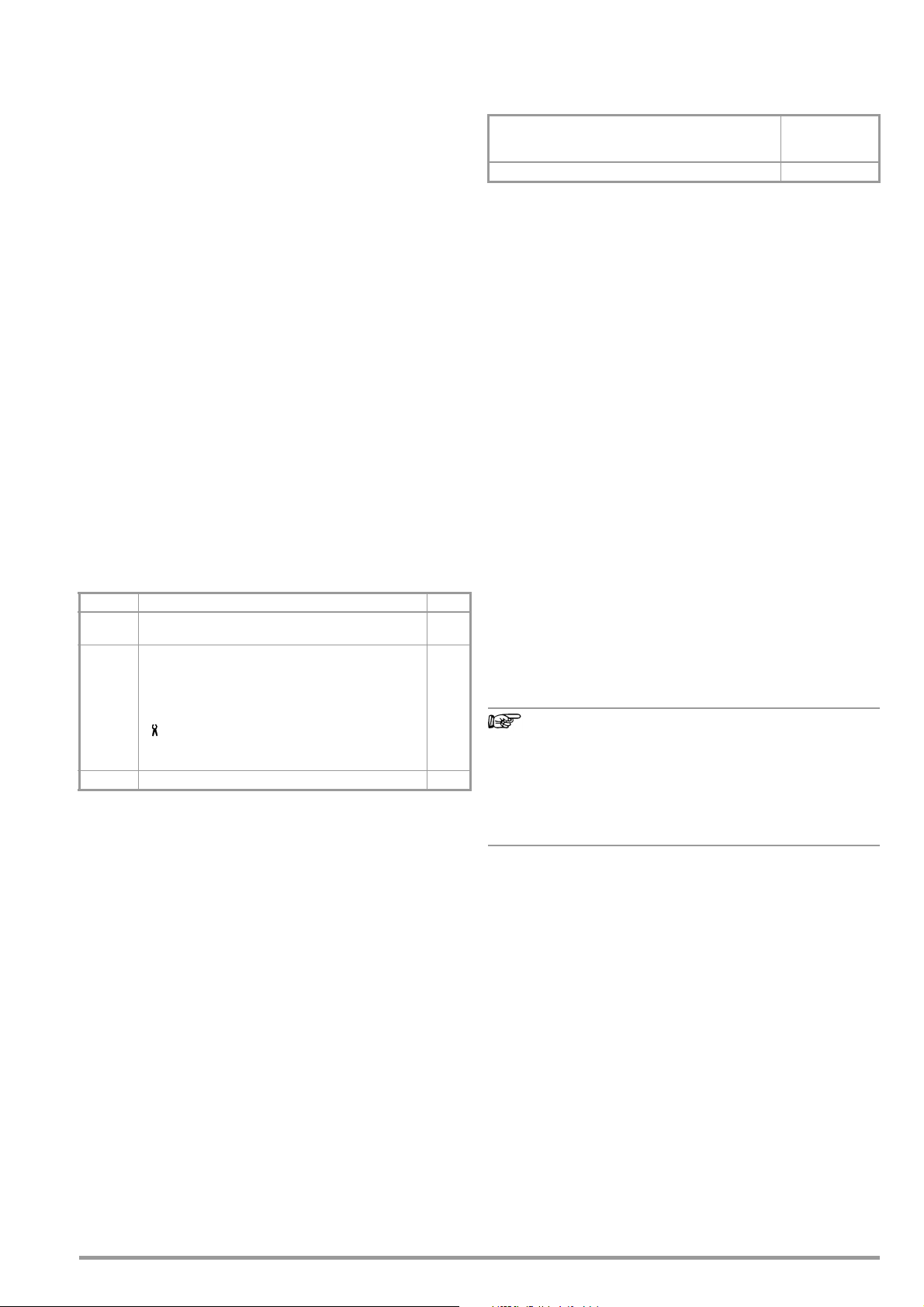
Measuring Categories and their Significance per IEC 61010-1
CAT Definition
Measurements in electrical circuits
0
which are not directly connected to the mains:
e.g. electrical systems in motor vehicles and aircraft, batteries etc.
Measurements in electrical circuits
II
which are electrically connected to the low-voltage mains:
via plug, e.g. in household, office and laboratory applications
Measurements in building installations:
III
stationary consumers, distributor terminals, devices connected permanently to
the distributor
Measurements at power sources for low-voltage installations:
IV
meters, mains terminals, primary overvoltage protection devices
The measuring category and the maximum rated voltage which
are printed on the device apply to your measuring instrument, e.g.
1000 V CAT III.
Refer to chapter 10.2 regarding use of the measurement cables.
Observe the following safety precautions:
• The multimeter may not be used in potentially explosive atmospheres.
• The multimeter may only be operated by persons who are
capable of recognizing touch hazards and taking the appropriate safety precautions. Touch hazards in accordance with the
standard exist anywhere, where voltages of greater than 33 V
(RMS) or 70 V DC may occur. Avoid working alone when taking measurements which involve touch hazards. Be certain
that a second person is present.
• Maximum allowable voltage
between the voltage measuring sockets or all connector
sockets and ground is 1000 V for measuring category III and
600 V for measuring category IV.
• Be prepared for the occurrence of unexpected voltages at
devices under test (e.g. defective devices). For example,
capacitors may be dangerously charged.
• Make certain that the measurement cables are in flawless
condition, e.g. no damage to insulation, no interruptions in
cables or plugs etc.
• No measurements may be made with this instrument in electrical circuits with corona discharge (high-voltage).
• Special care is required when measurements are made in HF
electrical circuits. Dangerous pulsating voltages may be present.
• Measurements under moist ambient conditions are not permitted.
• Be absolutely certain that the measuring ranges are not overloaded beyond their allowable capacities. Limit values are
included in chapter 8, “Characteristic Values”, in the table entitled “Measuring Functions and Measuring Ranges” in the
“Overload Capacity” column.
• The multimeter may only be operated with installed rechargeable
batteries or mains module. Dangerous currents and voltages are otherwise not indicated, and the instrument may be damaged.
• Weak (insufficiently charged) rechargeable battery
If the “weak battery” icon appears in the battery level indicator,
it’s no longer permissible to perform safety-relevant measurements. Furthermore, compliance with the listed specifications
is no longer assured in the case of a weak rechargeable battery.
• The instrument may not be operated if the fuse cover, the
rechargeable battery pack or the mains module has been
removed, or if its housing is open.
• The input for the current measuring range is equipped with a
fuse link.
Maximum permissible voltage for the measuring circuit (=
rated voltage of the fuse) is 1000 V AC/DC.
Use specified fuses only (see page 49)! The fuse must have a
breaking capacity of at least 30 kA.
Opening the Instrument / Repairs
The instrument may only be opened by authorized, trained personnel in order to ensure flawless operation and to assure that the
guarantee is not rendered null and void.
Even original replacement parts may only be installed by authorized, trained personnel.
If it can be ascertained that the instrument has been opened by
unauthorized personnel, no guarantee claims can be honored by
the manufacturer with regard to personal safety, measuring accuracy, compliance with applicable safety measures or any consequential damages.
If a guarantee seal is included and it has been damaged or
removed, all guarantee claims are rendered null and void.
Repair and Replacement of Parts by Authorized, Trained Personnel
When the instrument is opened, voltage conducting parts may be
exposed. The instrument must be disconnected from the measuring circuit before performing repairs or replacing parts. If repair of
a live, open instrument is required, it may only be carried out by
trained personnel who are familiar with the dangers involved.
Defects and Extraordinary Strains
If it may be assumed that the instrument can no longer be operated safely, it must be removed from service and secured against
unintentional use.
Safe operation can no longer be relied upon:
• If the device demonstrates visible damage
• If the instrument no longer functions, or if malfunctioning
occurs
• After long periods of storage under unfavorable conditions
(e.g. humidity, dust or extreme temperature (see “Ambient
Conditions” on page 49)
GMC-I Messtechnik GmbH 5
Page 6
2.1 Use for Intended Purpose
Attention!
!
Attention!
!
!
• The multimeter is a portable device which can be held in the
hand during the performance of measurements.
• Only those types of measurements described in chapter 6
may be performed with the measuring instrument.
• The measuring instrument, including measurement cables
and plug-on test probes, may only be utilized within the specified measuring category (see page 53 and the table on
page 5 regarding significance).
• Overload limits may not be exceeded. See technical data on
page 47 for overload values and overload limits.
• Measurements may only be performed under the specified
ambient conditions. See page 49 regarding operating temperature range and relative humidity.
• The measuring instrument may only be used in accordance
with the specified degree of protection (IP code) (see
page 50).
Data Backup
We advise you to regularly transfer your stored data to a PC in
order to prevent potential loss of data in the test instrument.
We assume no responsibility for any data loss.
Battery Pack Safety Precautions
The test instrument is powered by a rechargeable lithium-ion battery. Consequently, it’s absolutely essential to observe the following points:
• Temperature ranges: The test instrument with battery pack must
not be exposed to direct sunlight or charged, operated or
stored at high temperatures, for example in a car.
The following ambient conditions apply to the battery pack:
– Charging mode (10 ... 45 °C): The battery may only be charged
within this temperature range.
– Measuring mode (–10 ... 50 °C): The battery may only be used
within this temperature range.
– Storage (–20 ... 50 °C): The maximum storage temperature is
50 °C.
• Excessive depletion: The rechargeable battery’s safety circuit
consumes minimal amounts of current. In order to prevent the
battery from becoming fully depleted, the instrument should
be connected to the mains for recharging at least once a year,
and preferably at more frequent, regular intervals. In some
cases it’s no longer possible to recharge a fully depleted battery, in which case it must be replaced by GMC-I Service
GmbH.
2.2 Meanings of Danger Symbols
Warning concerning a point of danger
(attention, observe documentation!)
Warning concerning dangerous voltage at the measurement
input: U > 15 V AC or U > 25 V DC
2.3 Meanings of Acoustic Warning Signals
Hi-voltage warning: > 1000 V (intermittent acoustic signal)
Heavy current warning: > 1 A (continuous acoustic signal)
Excessive depletion should be avoided because the battery’s service life might otherwise be reduced, or the battery could fail. The battery pack is subject to selfdischarging at a rate of roughly 25% per year.
Battery pack transport:
Observe the supplementary sheet with safety information
for the Z270A or Z270G battery pack with rechargeable
lithium-polymer battery
(3-349-997-15 oder 3-447-030-15)!
The supplementary sheet with safety information for the Z270A/
Z270G battery pack is included with the manufacturer’s safety
data sheet for the installed lithium-polymer battery.
6 GMC-I Messtechnik GmbH
Page 7
3 Operating Overview
2
3
4
1
5
6
8
Chapter 3.2
Chapter 5.6
Chapter 9.2
Chapter 3.3
13
Max. 1000 V!
12
15
Chapter 4.4.4
14
Chapter 3.4
11
7
Chapter 3.5
9
10
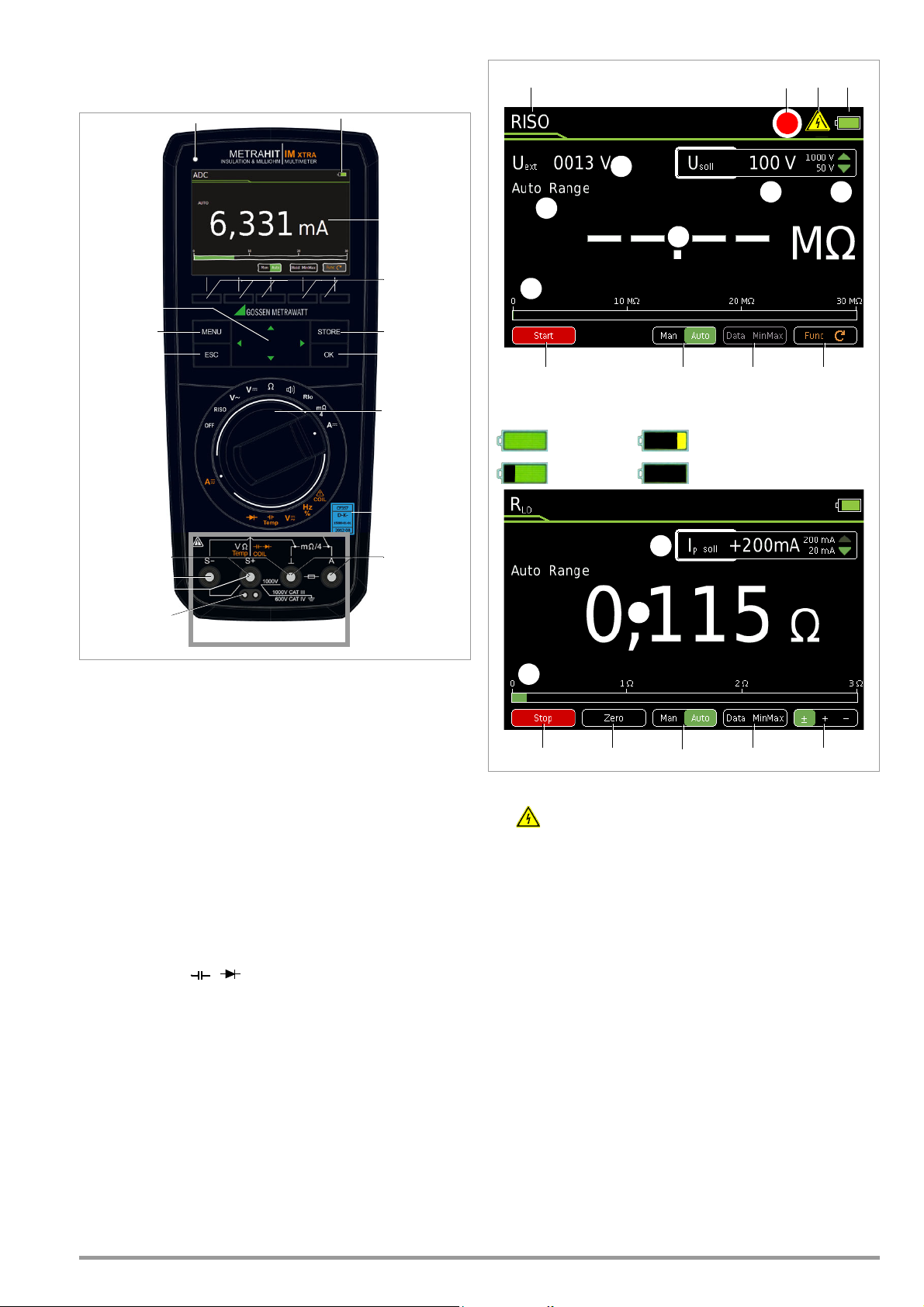
Battery full
Battery OK
Battery weak
Battery (almost) dead, U < 3.3 V
Charge Levels
1 3 4
567
8
11
12
3
109
135
6
1415
16
1%
REC
2
12
11
!
3.1 Connections, Keys, Rotary Switch, Symbols
3.2 Symbols Used in the Digital Display
1 Charging status LED (charging mode – yellow: battery is charging, green:
fully charged)
2 Display (TFT), see Chapter 3.2 for meanings of symbols
3 Softkeys (menu -dependent keys for selecting switching functions and
parameters, and for starting/ending measurements)
4 STORE: Save key or push/print function for IZYTRONIQ
5 OK: Key for acknowledgment and for restarting the instrument from the
standby mode by pressing and holding
6
Rotary switch
7 DAkkS calibration seal
for measuring functions, (see page 8 for meanings of symbols
8 Connector sockets for current measurement with automatic blocking
earthing input
A current measurement input
9 S+/S–: sense terminals for 4-wire measurements (m /4)
10 Extended connection for Z270S probe
(operating instructions 3-349-996-15)
Connector sockets for voltage measurement with automatic blocking
11
earthing input
V, , Temp, M, , , COIL measurement input
12 ESC:
Operating mode menu:
Press key briefly: Exit the menu level – jump back to a higher level, exit
parameters entry without saving
Press and hold: The instrument is switched to the standby mode. Switch
back on by pressing and holding the OK key.
13 MENU: Key for accessing the five main menus.
14 Scroll keys:
Increase parameter values
Operating mode menu: Selection of individual menu items
Decrease values
Operating mode menu: Selection of individual menu items
Increase measuring range or move decimal point to right (
Decrease measuring range or move decimal point to left (
15 Brightness sensor
Man
Man
function)
function)
1 Momentary measuring function
2 Memory symbol
3 Important, in this case: Uext (interference voltage) or
warning regarding dangerous voltage: U > 15 V AC or U > 25 V DC
4 Battery charge level
5 Func: switch back and forth amongst the functions of a given rotary
switch position
6 Data MinMax: switch amongst “Data” (freeze measured value), “Min-Max
storage” and deactivate both functions
7 Man Auto: switch back and forth between manual and automatic measur-
ing range selection
8 Display of the selected measuring range with manual measuring range
selection:
Select a lower measuring range
Select a higher measuring range
9 Selected test voltage
10 Select test voltage:
Select a larger test voltage
Select a smaller test voltage
11 Digital display with decimal point and polarity display
Measuring range exceeded: OL is displayed
12 Scale for analog display
13 Polarity selection
14 Zero: Zero balancing active
15 Start/Stop: For measurements which are not started automatically
16 Ip: Test Current
GMC-I Messtechnik GmbH 7
Page 8
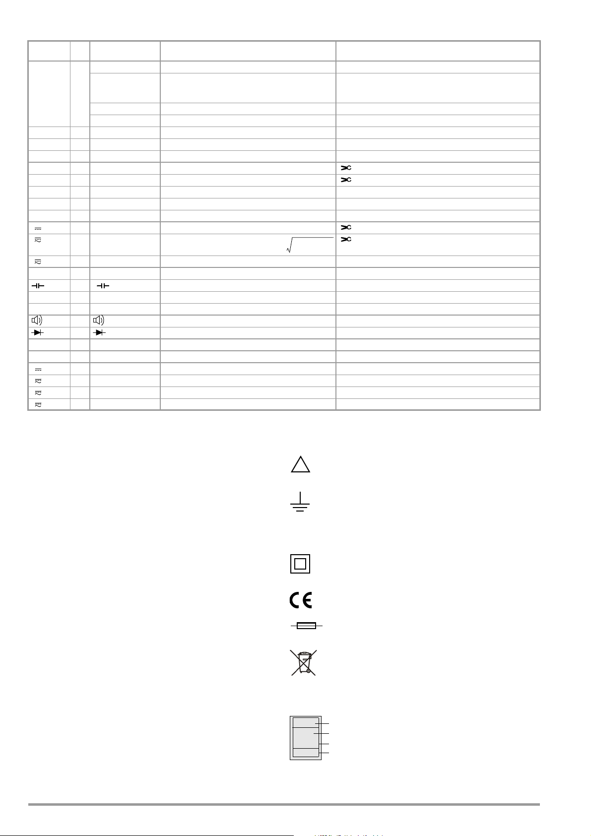
3.3 Symbols Used for Rotary Switch Positions
V
ACDC
V
AC
2
V
DC
2
+=
!
Consecutive number
Registration number
Date of calibration (year – month)
Deutsche Akkreditierungsstelle GmbH – calibration lab
XY123
2019-04
D-K-
15080-01-01
Switches
RISO 0/4 RISO M Insulation resistance measurement
Coil 1 Coil L1, L2, L3 [μs] Short-circuited coil test with optional COIL adapter
Coil 2 DAR [k/s] Dielectric absorption rate
Coil 3PI [k/s] >Polarization index
V~ 0/5 VAC Alternating voltage, AC TRMS, full bandwidth
Hz 1 Hz Voltage frequency, full bandwidth
Hz 2 Duty AC %
Hz 3RPM AC
V~ 4V AC Fil
V 0/3 VDC
V 1V (AC+DC)
FUNC
Display Measuring Function
Uext
Uset Selectable test voltage: 50, 100, 250, 500or 1000 V
UISO Applied/measured test voltage during measurement
1
1
Pulsating voltage, TRMS DC + AC, 15 Hz ... 500 Hz,
only for detection of interference voltage! (before starting
measurement)
Duty cycle measurement
RPM measurement
Alternating voltage, AC TRMS, with low-pass filter (1 kHz)
Direct voltage DC clamp (V): Current clamp sensor
Pulsating voltage, TRMS
Additional Current Clamp Sensor Function Clip = 1:1/10/100/1000
(via the “Setup for currently selected measurement” menu)
AC clamp (V): Current clamp sensor
Hz client (V): Current clamp sensor
AC + DC clamp (V): Current clamp sensor
V 2V (AC+DC) Fil
0/4 (DC) resistance
1F, nF, F Capacitance
Temp. RT D 2 C Pt 100/1000
Temp. TC 3 C, type K Temperature, type K thermocouple
0/2 Continuity test with acoustic signal
1
Rlo 0R
m/4 0R
A 0/4 ADC Direct current amperage
A 1 A (AC+DC) Pulsating current amperage, AC DC TRMS
A 2 AAC Alternating current amperage, AC TRMS
A 3 Hz Current frequency
1
Clip = off
LO/2L 2-wire milliohm measurement where IP = /+/- 200 mA
LO/4W 4-wire milliohm measurement where IP = 200 mA or 1 A
1
Pulsating voltage, TRMS AC DC, with low-pass filter (1 kHz)
Temperature with Pt 100 / Pt 1000 resistance thermometer
V Diode voltage where I is constant
3.4 User Interface Symbols in the Following Sections
... Scroll through main menu
... Scroll through submenu
Select decimal point,
increase/decrease measuring range
Increase/decrease value
(test voltage for insulation resistance measurement or
threshold for continuity test)
3.5 Symbols on the Instrument
Warning concerning a point of danger
(attention, observe documentation!)
Ground
CAT III / IV
Measuring category III or IV device, see also “Measuring Categories and their Significance per IEC 61010-1” on page 5
Continuous, doubled or reinforced insulation
Indicates European Conformity
Fuse for current measuring ranges, see chapter 9.3
This device may not be disposed of with the trash. Further information regarding the WEEE mark can be
accessed on the Internet at www.gossenmetrawatt.com
under the search term WEEE (see also chapter 9.6).
Calibration seal (blue seal):
See also “Recalibration” on page 53
8 GMC-I Messtechnik GmbH
Page 9
4 Initial Startup
Attention!
!
Note
MENU
MENUOKESC
MENU
OKOKESC
MENU
OKOKESC
MENU
OKOKESC
4.1 Battery Pack
Be certain to refer to Chapter 9.2 regarding correct installation of the battery
pack!
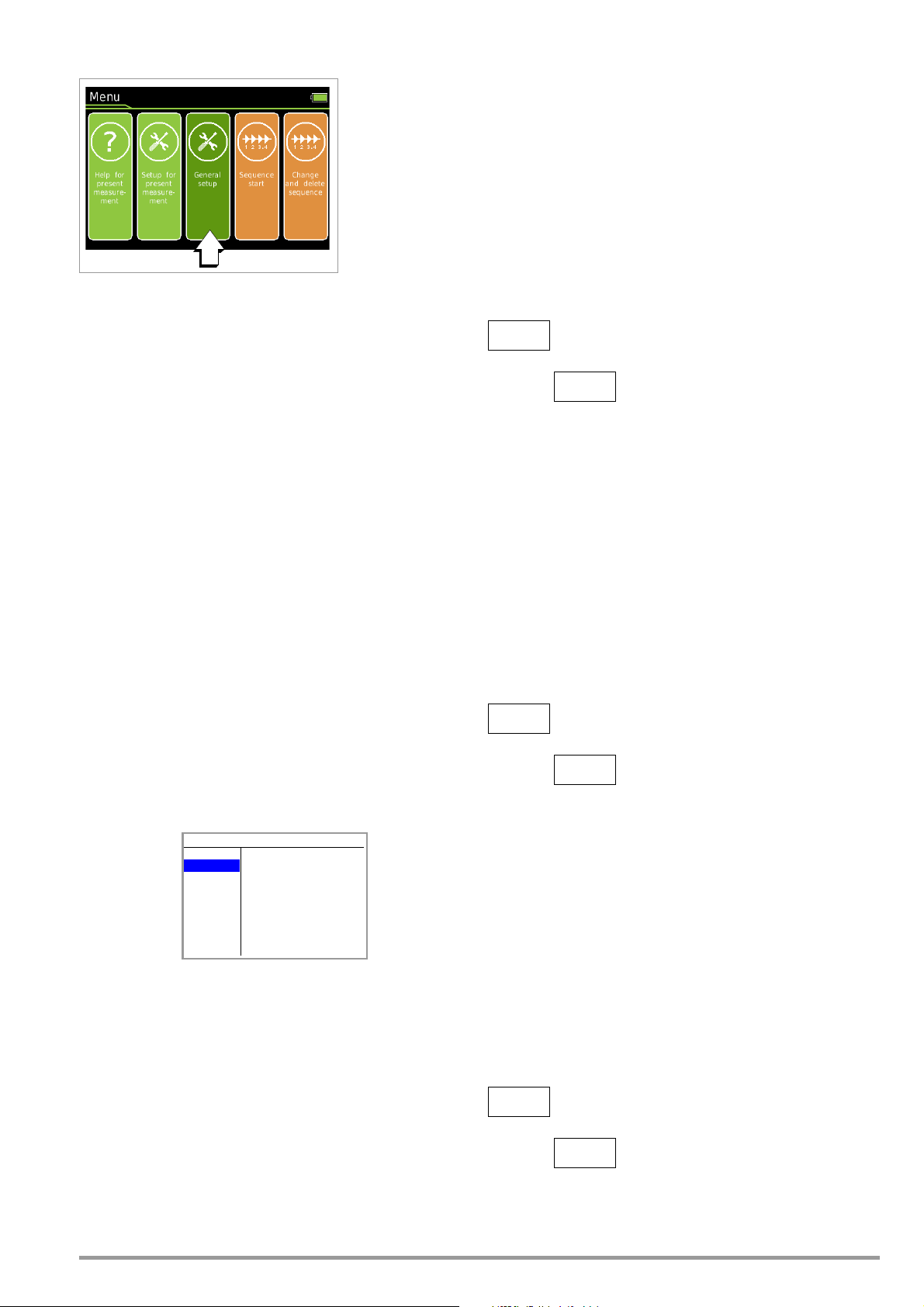
Momentary battery capacity can be queried by clicking the Info
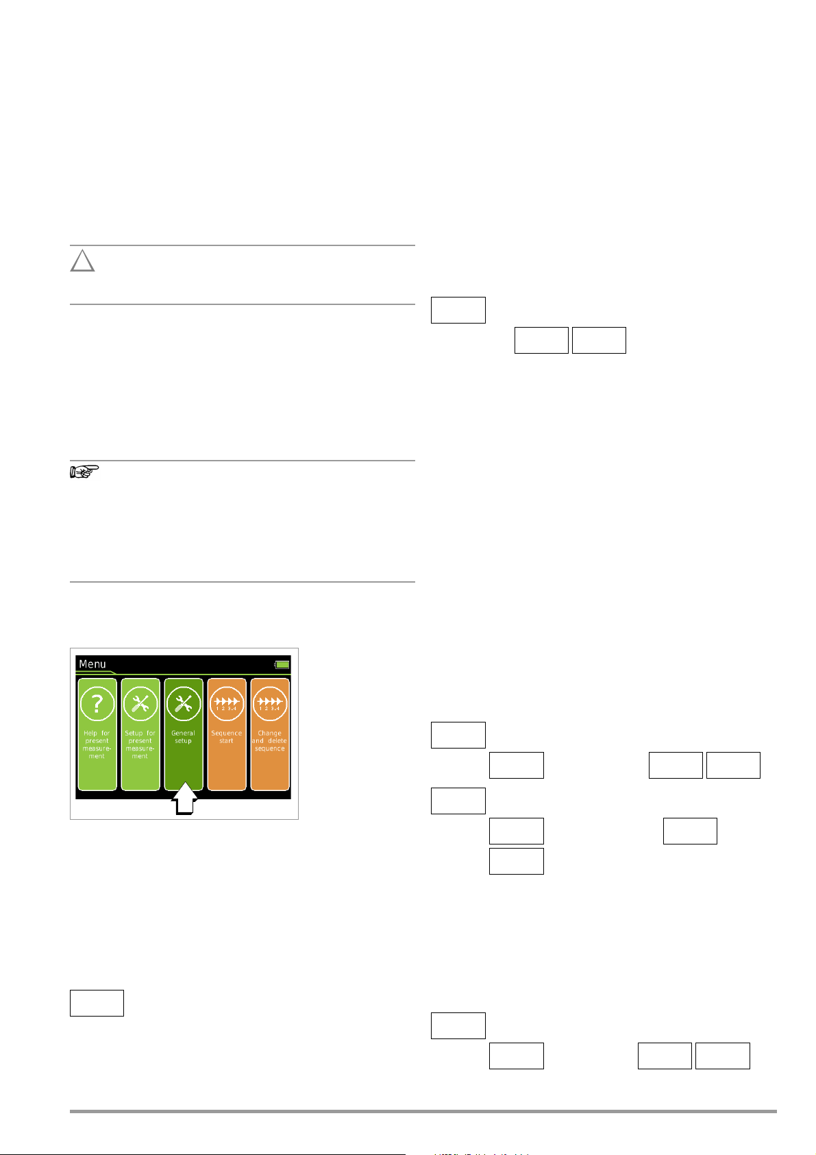
item in the General Setup menu:
➭ Press the MENU key to this end.
➭ Then press the General Setup softkey.
➭ Select the Info parameter with the help of the scroll keys.
The “Battery” parameter indicates the battery pack’s charge level
as a percentage.
Disconnect the instrument from the measuring circuit before removing the battery pack for charging!
4.2 Mains Module
In preparation
4.4.2 Language >German/English – Selecting the User Interface Language
➭ Press the MENU key.
➭ Press the General Setup softkey.
➭ Select the Language parameter with the help of the
keys.
➭ Switch to the settings menu with the help of the scroll key.
➭ Select the desired language with the
➭ Acknowledge by pressing the OK key. The input cursor jumps
back to the parameters list.
➭ Return to the main menu by pressing the ESC key or the MENU
key.
➭ The instrument is returned to the measuring mode after press-
ing the ESC key once more.
> General Setup > Language German/English
2x
scroll keys.
scroll
4.3 Switching the instrument On
Switching the Instrument On Manually
➭ The instrument is switched on automatically after selecting
any rotary switch position other than OFF.
Electrical discharge and high frequency interference may
cause incorrect displays to appear, and may disable the
measuring sequence.
Disconnect the device from the measuring circuit. Switch the
instrument off and back on again in order to reset. If the
problem persists, briefly dislodge the battery from the
connector contacts (see also chapter 9.2).
4.4 Querying or Setting Operating Parameters – General Setup
4.4.3 System > Date/Time – Setting Date and Time
➭ Press the MENU key.
➭ Press the General Setup softkey.
➭ Select the System parameter with the help of the
keys.
➭ Switch to the submenu with the help of the
➭ Select the Date or Time parameter with the help of the
scroll keys.
➭ Acknowledge the selected parameter by pressing the OK key.
The entry cursor jumps to a random position in the settings
menu.
➭ Select the desired entry position with the scroll keys and
change the respective value with the scroll keys.
➭ Acknowledge the change with the OK key. The entry cursor
once again marks the entire parameter line.
➭ Return to the main menu by pressing the ESC key twice or the
MENU key once.
➭ The instrument is returned to the measuring mode after press-
ing the ESC key once more.
> General Setup
System Time
09:50:20
3x
scroll
scroll key.
> General Setup
4.4.1 Info > Version – Check Current Software Version
➭ Press the MENU key.
➭ Press the General Setup softkey.
➭ Select the Info parameter with the help of the
➭ The version parameter indicates the current software (firm-
ware) revision level.
➭ The instrument is returned to the measuring mode after press-
ing the ESC key twice.
> General Setup >
GMC-I Messtechnik GmbH 9
Info > Version
scroll keys.
4.4.4 System > Brightness – Digital Display Brightness
Brightness of the digital display can be set between 1 (minimum
brightness) and 9 (maximum brightness).
It can also be set to automatic. In this case, digital display brightness is adjusted depending on the intensity of the light which
strikes the brightness sensor.
> General Setup System Brightness:
System Date
13:06:2017
3x
1 ... 9, Auto
3x
Page 10
4.4.5 System > Display Zeros
MENU
OKOKESC
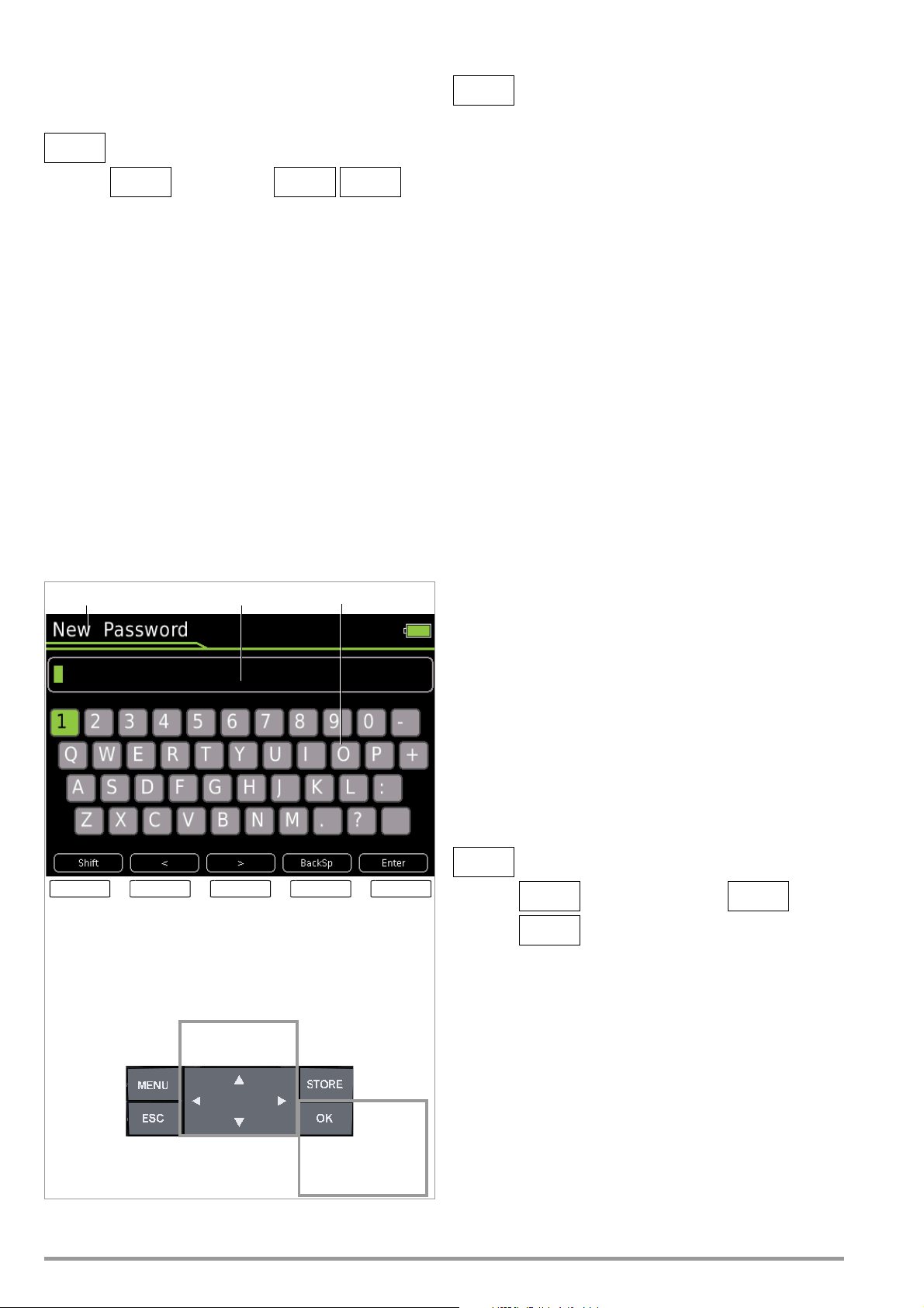
< > BackSp Enter
Entry Field Keypad
Shift
Entry Prompt
Entry field:
Delete
characters from
right
Entry field:
Accept
password from
entry field
Entry field:
Scroll left
Entry field:
Scroll
right
Keypad:
Switch
between
upper/
lower
case and
symbols
Char. Selection
in the Keypad
Transfer character
from the keypad to
entry field
MENU
MENU
OKOKESC
The Display Zeros parameter can be used to specify whether leading zeros will appear or be suppressed at the measured value display.
Entering the Old Password
> General Setup System
Change Password
> General Setup
System Display Zeros:
000.0 / 0.0
3x
4.4.6 System > Change Password
A password must be entered in order to adjust the parameters for
each of the following measurements:
• RISO: change test voltage
•M/4: change test current
The default password is “METRAHIT”.
If necessary, an individual password can be assigned via the
Change Password parameter.
Password protection is not activated with the default setting, i.e.
“METRAHIT”. An individual password must be entered in order to
activate this function.
Password Characteristics
Maximum length 31 characters
Composition: any desired alphanumeric characters
Keyboard for Entering Text
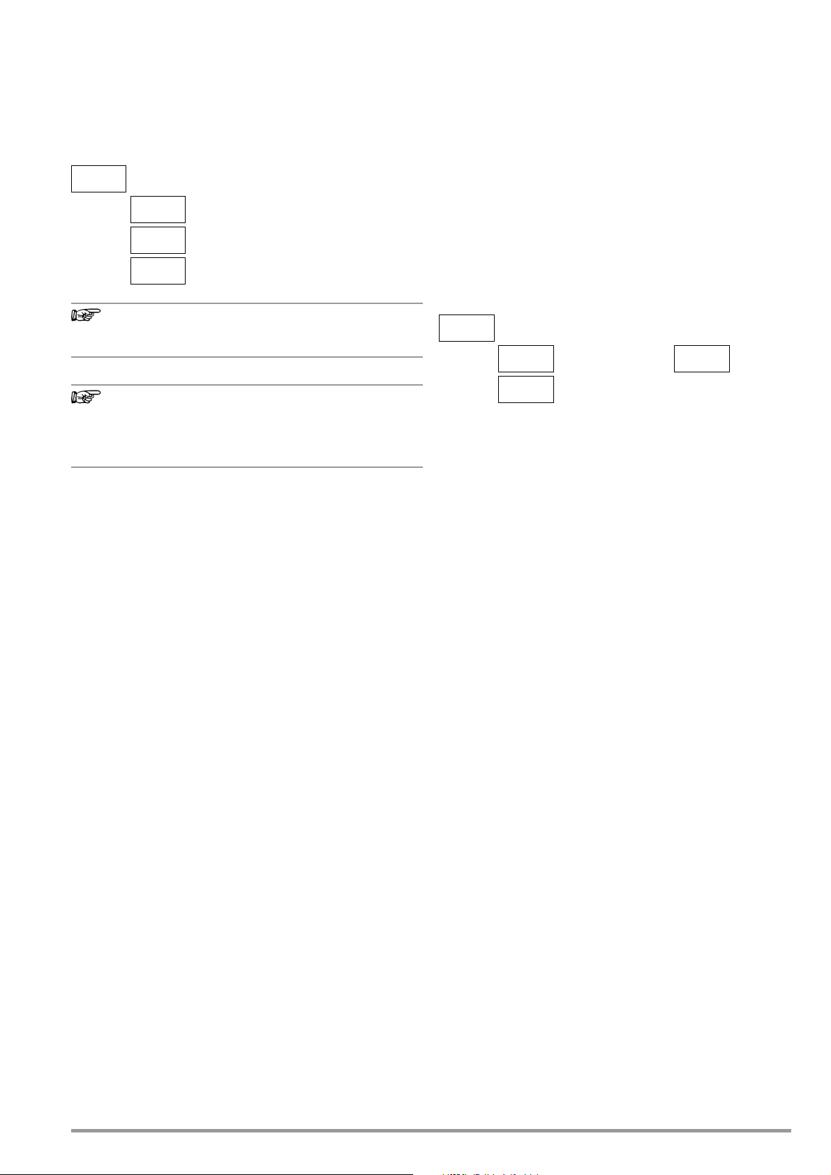
Press the MENU key and then press the “General Setup” softkey.
Select the “System” menu with the help of the
Switch to the submenu with the help of the
scroll key.
scroll key and
select the Change Password parameter using the scroll keys.
After acknowledging the Change Password parameter by pressing
the OK key, “Old Password” appears in the header in order to
prompt you to enter your current password.
Your current password is entered using the alphanumeric keyboard. Select the individual characters from the keypad using the
scroll keys to this end. The position of the cursor is indicated by
the green background at the respective key. Acknowledge the
selected character by pressing the OK key, after which the character is transferred to the entry field. The last entered character or
characters can be deleted with the help of the BackSp (backspace)
key. You can move the blinking cursor in the entry field to the
desired position within the word using the “<” or “>” softkey, in
order to add characters or delete them with the help of the BackSp
softkey. The Shift softkey can be used to switch back and forth
between upper and lower case letters, as well as numerals and
special characters. A fully entered (old) password is accepted by
pressing the Enter key. “New Password” appears in the header in
order to prompt you to enter a new password.
Entering the New Password
Enter a new password as described above. After acknowledging
by pressing the Enter softkey, “Confirm Password” appears at the
display and prompts you to enter the new password once again.
Proceed as described above to enter the password again, and
then acknowledge by pressing OK. If the exactly the same password has been entered both the first and the second time, the following message appears in order to indicate that the password
has been successfully changed: “The password has been
changed”.
The menu mode is exited by pressing ESC three times and the
instrument is returned to the measuring function.
4.4.7 System > Display Profile – Digital Display View
Two different views can be selected here – black lettering against
a bright background or vice versa.
> General Setup
Default setting: White lettering against a dark background
System Display Profile:
Inverted or Normal
3x
10 GMC-I Messtechnik GmbH
Page 11
4.4.8 System > Default Settings
Note
Note
MENU
OK
OK
ESC
MENU
OK
OK
ESC
All of the settings which you have changed can be returned to
their default settings here. The following warning appears after
pressing the OK button: “Reset?”. The parameter settings are not
reset until you acknowledge with “Yes” (scroll with
press OK). Resetting can be aborted by scrolling with to No
and pressing OK.
> General Setup
System Default Settings:
Yes / N o Pro m pt
3x
to Yes and
4.5 Switching the Instrument Off
Switching the Instrument Off Manually
➭ The instrument is switched off automatically by setting the ro-
tary switch to the OFF position. The display goes blank.
4.5.1 System > Auto-OFF – Automatic Shutdown
The period of time after which the instrument is shut down automatically regardless of whether a measuring or a menu view is
open can be set to a value within a range of 10 to 59 minutes.
The instrument is switched off automatically if the measured value
remains unchanged for a long period of time (maximum measured
value fluctuation of approx. 0.8% of the measuring range per minute or 1C or 1 per minute), and if none of the keys or the rotary
switch have been activated before a selected period of time in
minutes has elapsed. Shutdown is acknowledged with a brief
acoustic signal.
The password for changing the test voltage for insulation
resistance measurement is reset to METRAHIT.
If you adjust any settings deviating from the default settings, such as „Bluetooth = On“ or „Brightness = Auto“, it
may lead to a reduction in the service life specified in the
Characteristic Values.
> General Setup
System Auto-OFF:
10 ... 59 min/Off
3x
Exceptions
Transmission and memory mode operation, continuous operation
and whenever a dangerous voltage is applied to the input (U >
15 V AC or U > 25 V DC).
Deactivation (continuous operation)
Automatic shutdown can be deactivated.
Set the Auto-OFF parameter to Off in the System submenu of the
General Setup menu to this end.
GMC-I Messtechnik GmbH 11
Page 12
5 Control Functions
1/3
2/3
ESC
2/3
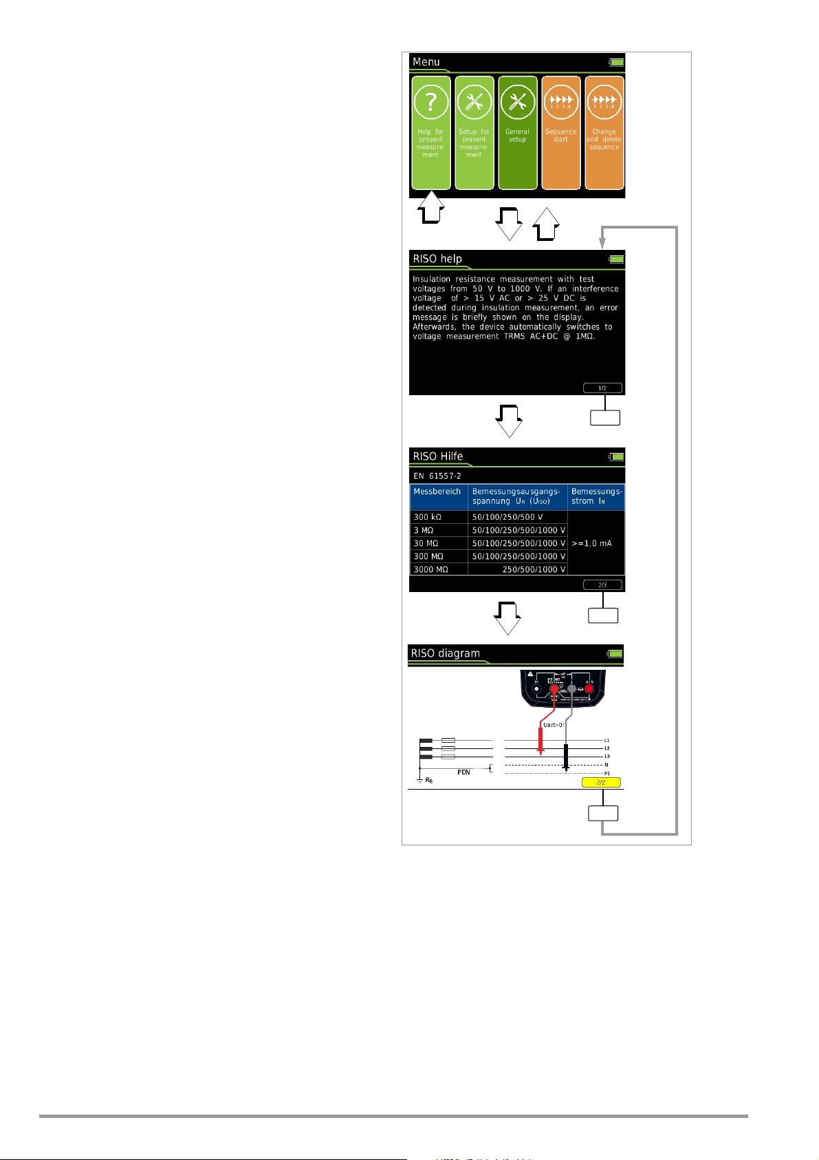
5.1 Help
The following information can be displayed for switch positions
and basic functions after they have been selected with the rotary
selector switch:
• Explanation of the measurement
• Measuring ranges
• Wiring diagram
➭ Press the MENU key to this end.
➭ Then press the “Help for currently selected measurement”
softkey. Comments concerning the measurement are displayed.
➭ By pressing the 1/3 softkey, the measuring ranges and test
voltages (2/3) are shown on the display.
➭ The wiring diagram (3/3) is displayed by pressing the 2/3 soft-
key.
➭ You can return to the help text (1/3) by pressing the 3/3 soft-
key.
➭ Press the ESC key once to return to the menu.
➭ The display can be returned to the measurement by pressing
the ESC key.
12 GMC-I Messtechnik GmbH
Page 13
5.2 Selecting Measuring Functions and Measuring Ranges
Note
5.2.1 Automatic Range Selection
The multimeter is equipped with auto-ranging for all measuring
functions except for temperature measurement, as well as diode
and continuity testing. Auto-ranging is active as soon as the instrument is switched on. The instrument automatically selects the
measuring range which allows for highest possible resolution of
the applied quantity. When the instrument is switched to frequency measurement, the previously selected voltage measuring
range remains active.
AUTO-Range Function
The multimeter is switched automatically to the next higher range
at (3099 d + 1 d 0310 d), and to the next lower range at
(280 d – 1 d 2799 d).
In the case of high resolution (available depending upon measuring function), the multimeter is switched automatically to the next
higher range at (30,999 d + 1 d 03100 d), and to the next
lower range at (2800 d – 1 d 27,999 d).
5.2.2 Manual Range Selection
Auto-ranging can be deactivated and measuring ranges can be
selected manually in accordance with the following table by
pressing the Man / Auto button.
The desired measuring range can then be selected with the
or scroll key.
The instrument is automatically returned to automatic range selection when the Man / Auto key is pressed, the rotary switch is activated or the instrument is switched off and back on again.
Overview: Auto-Ranging and Manual Range Selection
Function Display
Man / Auto
Range switching sequence for:
V: 300 mV*
Hz: 300 Hz
:
300
or
Man / Auto
* Only via manual range selection for V AC
A:
300A
A : 0.3 A 3 A 30 A 300 A
F:
30 nF
RISO:
300 k
Return to automatic measuring range selection Auto
Manual mode active:
utilized measuring range is fixed
3 V 30 V 300 V 1000 V
3 kHz 30 kHz 300 kHz (Hz(U))
3 k
30 k
3 mA
30 mA
300 nF 3 F 30F
3 M
30 M
300 M
300 k
3 M
300 mA
30 M
1 A
300F
3000 M
Man
Man
The multimeter is held in the selected measuring range. If the
range limit is exceeded, “OL” appears at the display. You should
then switch to the next higher measuring range with the help of
scroll key.
the
5.2.3 Quick Measurements
Measurements performed using a suitable fixed measuring range
are executed more quickly than those which utilize automatic
range selection. Quick measurement is made possible with the
following two functions:
• Manual measuring range selection, i.e. by selecting the measuring
range with the best resolution (see Chapter 5.2.2)
or
•With the DATA function (see Chapter 5.5) In this way, the appro-
priate measuring range is selected automatically after the first
measurement and the second measurement is executed more
quickly.
The selected measuring range remains active for the subsequent
series of measurements with these two functions.
5.3 Zero Offset / Relative Measurements
Zero offset or a reference value for relative measurements can be
stored to memory depending upon deviation from the zero point:
Deviation from zero point
– with short-circuited measurement cables for V, , A
– with open input for capacitance unit of measure F
0 ... 200 digits
Display
ZERO
The relevant reference or correction value is deducted individually
for the respective measuring function as an offset from all future
measurements and remains in memory until deleted, or until the
multimeter is switched off.
Zero balancing and reference value adjustment can be used with
auto-ranging, as well as for manual measuring range selection.
Note:
Zero offset is available for the following measuring functions and
switch positions: RISO, Coil, DAR, PI, Hz, Duty AC, RPM AC, ,
Temp RTD (the RLeads function is offered here as an alternative),
Temp TC, Continuity, Diode, R
pressing the START key!) and R
/2L (ZERO is also activated after
LO
/4L (the thermal compensation
LO
function is offered here as an alternative).
Zero Balancing
➭ Plug the measuring cables into the instrument and connect
the free ends to each other, except for capacitance measurement and current measurement in which case the ends of the
cables are not connected to each other.
➭ Briefly press the Zero softkey.
The value measured at the moment the key is pressed serves
as a reference value. The instrument acknowledges zero balancing with an acoustic signal, and “Zero” and the reference
value appear at the display. The Zero softkey is displayed with
a green background.
➭ Zero balancing can be cleared by once again pressing the
Zero softkey.
As a result of TRMS measurement, the multimeter displays a residual value of 1 to 10/35 digits with short-circuited measurement cables as the zero point for V AC / I
AC or V(AC+DC) / I (AC+DC) measurements (non-linearity of the TRMS converter). This has no influence on
specified accuracy above 1% of the measuring range (or
3% in the mV, V(AC+DC) ranges).
Setting the Reference Value
➭ Plug the measuring cables into the instrument and measure a
reference value (max. 50% of measuring range).
➭ Briefly press the Zero softkey.
The instrument acknowledges storage of the reference value
with an acoustic signal and the “ZERO” symbol appears at the
display. The value measured at the moment the key is
pressed serves as a reference value.
➭ The reference value can be cleared by once again pressing
the Zero softkey.
Notes Regarding Relative Measurement
• Relative measurement effects the digital display only.
The analog display continues to read out the original measured value.
• In the case of relative measurement, F or AC quantities may
also appear as negative values.
GMC-I Messtechnik GmbH 13
Page 14

5.4 Display (TFT)
5.4.1 Digital Display
Measured Value, Unit of Measure, Type of Current, Polarity
The measured value with decimal and plus or minus sign appears
at the digital display. The selected unit of measure and current
type are displayed as well. A minus sign appears to the left of the
value during the measurement of zero-frequency quantities, if the
plus pole of the measured quantity is applied to the “” input.
The Display Zeros parameter can be used to determine whether
leading zeros will appear or be suppressed at the measured value
display (see chapter 4.4.5).
Exceeded Measuring Range
If the upper range limit of 1000 digits is exceeded “OL” (overload)
appears at the display.
Exceptions: “OL” appears at the display as of 1030.0 V in the
case of voltage measurement in the 1000 V range, as of 5100 V
for diode testing and as of 1.100 A in the 1 A range.
5.4.2 Analog Display
Measured Value, Polarity
The analog display demonstrates the dynamic performance of a
moving-coil mechanism. This display is especially advantageous
for observing measured value fluctuation, and for balancing procedures.
Display as a horizontal (green) bar which indicates the current
measured value in real-time.
The analog scale displays a small negative range for the measurement of zero-frequency quantities with positive measured values,
allowing for precise observation of measured value fluctuation
around zero. If the measured value exceeds a certain negative
range, polarity is reversed at the analog display.
The analog scale displays a small positive range for the measurement of zero-frequency quantities with negative measured value,
allowing for precise observation of measured value fluctuation
around zero in this case as well.
Scaling of the analog scale is automatic. This is very helpful for
manual measuring range selection.
Exceeded Measuring Range
Exceeding the measuring range is indicated exclusively via the
digital display.
Refresh Rate
The analog display is refreshed 40 times per second.
14 GMC-I Messtechnik GmbH
Page 15
5.5
Note
V, A, Hz
t [s]
100%
10%
Activated
Reactivated
Save
Save
3000 Digits
Of Measuring Range
F, %
Measured Value Storage – Data Function (auto-hold/compare)
General
An individual measured value can be automatically “frozen” with
the DATA function (auto-hold).
Applications
This function is useful, for example, when contacting the measuring points with the test probes requires your full attention. After
the measuring signal has been applied and the measured value
has settled in in accordance with the “condition” listed in the table
below, the measured value is frozen at the digital display and an
acoustic signal is generated. The test probes can now be
removed from the measuring points, and the measured value can
be read from the digital display. If the measuring signal falls below
the value specified in the table, the function is reactivated for storage of the next value.
The Data function can be activated in all measuring functions. This
is possible for the following functions after measurement has
been started: RISO, R
/2L and RLO/4L.
LO
Procedure
Apply the measured quantity to the instrument and set the measuring range with the Man / Auto softkey before activating the Data
function with the Data / MinMax softkey. Man appears at the display
with a green background. After activating the Data function with
the corresponding softkey, Man is grayed out and cannot be
changed until Data / MinMax is pressed again three times for deactivation. Data appears at the display with a green background. If
automatic measuring range selection was active prior to activation
of the Data function, switching to manual measuring range selection is also disabled as long as the MinMax function is active.
Data and the associated value appear between the digital and
analog displays.
Condition Response from Instrument
Meas.
Function
V, A, F, Hz, %> 10%
V, A, F, Hz, %< 10%
Measuring
Signal
rdg.
0L
MR
= 0L
Display
Data + MV
Is
displayed
Is
displayed
Stored MV
Is
cleared
Acous-
tic
1 x
1 x
2 x
1 x
2
Function
Data
Activate Short
Save
(stabilized
measured
value)
Reactivate
Change to
MinMax
1
Reactivation results from falling short of specified measured value limits.
2
Two acoustic signals are generated the first time a measured value is
saved as a reference value. For subsequent data hold, two acoustic signals are only generated if the currently frozen value deviates from the first
saved value by less than 100 digits.
Data / Min-
1
Key
Max
Short
Key: MV = measured value, MR = measuring range
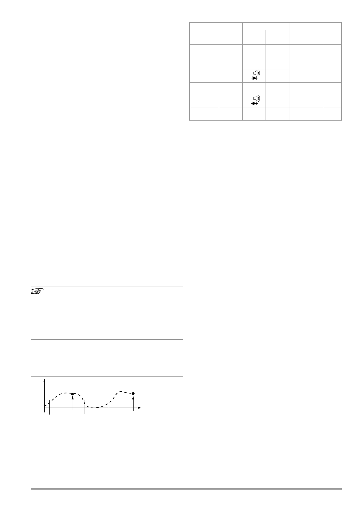
Example
The voltage measuring range is set manually to 30 V.
The first measured value is 5 V and is stored to memory because
it’s greater than 10% of the measuring range (= 3 V), and is thus
reliably above the background noise level. As soon as the measured value drops to less than 10 % of the measuring range, i.e.
amounts to less than 3 V which corresponds to removal of the
test probes from the measuring point, the instrument is ready to
store a new value.
Measured Value Comparison (DATA Compare)
If the currently frozen value deviates from the first saved value by
less than 100 digits, the acoustic signal is generated twice. If deviation is greater than 100 digits, only a brief acoustic signal is generated.
The Data function has no effect on the analog display, at
which the current measured value continues to appear.
However, when the digital display is “frozen”, the decimal
point is fixed as well (fixed measuring range, Man appears
with a gray-green background).
The selected measuring range cannot be manually
changed as long as the Data function is active.
The Data function is deactivated by briefly pressing the Data / Min-
Max softkey three times, if you switch to the MinMax function,
when the measuring function is changed or when the instrument
is switched off and back on again.
GMC-I Messtechnik GmbH 15
Page 16
5.5.1 Saving Minimum and Maximum Values – “MinMax”
Note
START
STORE
Test T i p
Safety Cap
Safety Collar
Z
2
7
0
S
REC
S– A
V
Tem p
m/4
COIL
S+
KS17-2
General
Minimum and maximum measured values applied to the measuring instrument’s input after the MinMax function has been activated can be “frozen” at the display.
Applications
The most important use of this function is the determination of
minimum and maximum values during long-term measured value
observation. The MinMax function can be activated in all measuring functions. This is possible for the following functions after
measurement has been started: RISO, R
/2L and RLO/4L.
LO
The MinMax function has no effect on the analog display, at which
the current measured value continues to appear.
Procedure
Apply the measured quantity to the instrument and set the measuring range with the Man / Auto softkey before activating the Min-
Max function with the Data / MinMax softkey. Man appears at the
display with a green background. After activating the MinMax
function with the corresponding softkey, Man is grayed out and
cannot be changed until MinMax is pressed again for deactivation.
MinMax appears at the display with a green background. If automatic measuring range selection was active prior to activation of
the MinMax function, switching to manual measuring range selection is also disabled as long as the MinMax function is active.
Both Min and Max, as well as the associated values, are displayed
between the digital and analog displays along with the time of
their occurrence.
The MinMax function is deactivated by briefly pressing the Data /
MinMax softkey, when the measuring function is changed or when
the instrument is switched off and back on again.
As opposed to the Data function, the MinMax function can
also be used for temperature measurement.
The MinMax function is reset by pressing the ESC key.
After pressing Data / MinMax once again, the minimum and maxi-
mum values are displayed together with the average value
(“Avg.”). The Min Avg Max display appears without timestamp.
MinMax
Function
Activate
and save
Save and
display
Stop Short Are deleted
Data /
MinMax
Key
Short
Min. and Max.
Measured Values
Are
saved
Storage continues in
background,
new min. and max. values are
displayed.
Response from Instrument
Display
Min + MV
Max + MV
Current
Measured value
Stored min. value 1 x
Stored max. value 1 x
cleared
Is
Acous-
tic
Signal
1 x
1 x
5.6 Measured Value Memory – STORE Function.
The following options are available for the storage of measured
values:
• Store at instrument by pressing the STORE key on the instrument
• Store at instrument by pressing the STORE key on the probe
• Store at the PC by triggering the PUSH/PRINT function in the
report generating program IZYTRONIQ
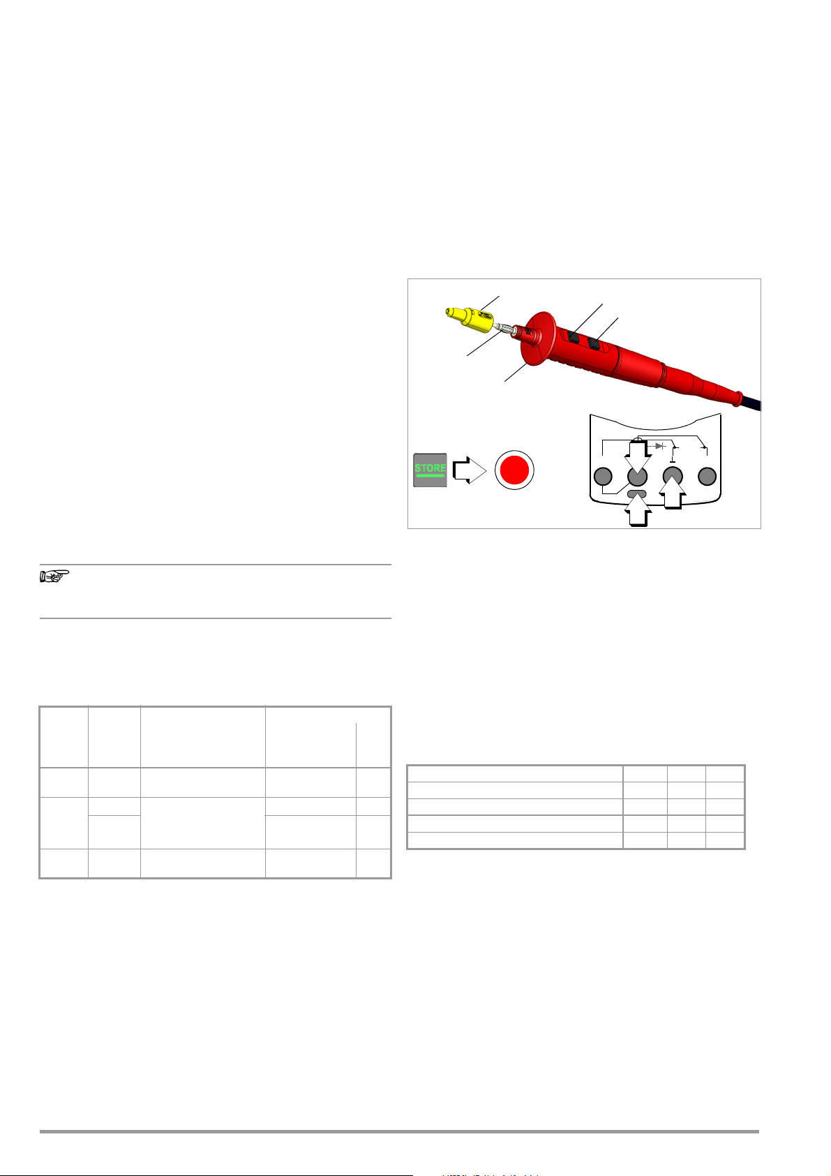
5.6.1 Remote read-out and storage via the Z270S probe
The probe with integrated control unit permits remote triggering at
difficult to access places, and at locations which require your full
attention. The probe can be used for all measuring functions
except for current measurement. The connector cable is shielded
against interference.
➭ Connect the probe’s double plug to the voltage socket (V).
➭ Connect the KS17-2 safety measurement cable to the ground
socket.
➭ Establish contact with the measuring point.
➭ Start the respective measuring function by pressing the START
key on the probe.
➭ As soon as the measured value has settled in, it can be stored
by pressing the STORE key on the probe.
Alternatively, the measured value can be stored with the help
of the STORE key on the instrument.
The REC storage symbol appears briefly in the header in order to
visualize the storage process.
Electrical Safety
Maximum rated voltage 300 V
Measuring category
Maximum rated current 1 A 1 A 16 A
With safety cap attached —
Without safety cap — —
600 V
CAT IV CAT III CAT II
Measurements per DIN EN 61010-031 may only be performed in
environments in accordance with measuring categories III and IV
with the safety cap attached to the control unit’s test tip.
In order to establish contact inside 4 mm sockets, the safety cap has
to be removed by prying open the snap fastener with a pointed
object (e.g. the other test probe).
5.6.2 Remote Read-Out and Storage via the PC – PUSH/PRINT
Function
The procedure for storage via the PUSH/PRINT function is
described in the online help included with IZYTRONIQ report generating software.
600 V
16 GMC-I Messtechnik GmbH
Page 17
5.7 Measurement Data Recording
System
Memory
Interface
Information
Language
General Setup
Recording
Record type
Sampling rate
Recording time
Hysteresis
Trigger
Trigger, low limit
Tri gger , high lim it
Groups
Clear memory
Start
Periodic
00:00.5
Unlimited
Off
Within
+00000
+01000
...
...
MENU
OK
MENU
OK
MENU
OK
The multimeter is capable of recording measurement data with
adjustable sampling rates, hysteresis and trigger conditions for
long periods of time in the form of measurement series (Parameter Record type = Periodic). Data are stored to a battery-backed
memory module, and are retained even after the multimeter is
switched off. The system acquires measured values relative to
real-time.
Momentary or stored measurement data can be read out via a
bidirectional wireless interface, Bluetooth or WiFi, or the USB port
at the optional mains module. IZYTRONIQ software is required to
this end.
See also interface operation chapter 7.
➭ First set the sampling rate for memory mode operation (see
below).
➭ Set recording time to Unlimited or to a value within a range of
0:00:00 to 90:00:00.
➭ Select an hysteresis in order to assure efficient use of memory
capacity.
➭ Select a trigger function if required.
➭ Check current memory occupancy (see below).
➭ Before starting lengthy measured value recordings, check the
battery’s charge level (see chapter 4.1) or use the mains module.
➭ Start memory mode operation (see below).
➭ First select the desired measuring function and an appropriate
measuring range.
Setting the Record Type
In this menu, you can choose between a definable periodic and
fixed sampling rate (parameter Periodic) and a one-off storage of a
data value by means of the STORE key (parameter Data Value).
➭ Press the MENU key.
➭ Press the General setup softkey.
➭ Select the Memory menu with the
scroll keys.
➭ Switch to the submenu with the help of the scroll key.
➭ Select the Record type parameter with the
scroll keys.
➭ Acknowledge the selected parameter by pressing the OK key.
➭ Change the respective value using the
scroll keys.
➭ Acknowledge the change with the OK key. The entry cursor
once again marks the entire parameter line.
> General setup
Memory Record type
Periodic / Data Value
Setting the Sampling Rate
This parameter cannot be set during memory mode operation.
Proceed as follows in order to set the sampling rate:
➭ Press the MENU key.
➭ Press the General Setup softkey.
➭ Select the Memory menu with the
➭ Switch to the submenu with the help of the
➭ Select the Sampling Rate parameter with the
scroll keys.
scroll key.
scroll keys.
➭ Acknowledge the selected parameter by pressing the OK key.
➭ Change the respective value using the
scroll keys
[h:mm:ss] or [mm:ss:s/10].
➭ Acknowledge the change with the OK key. The entry cursor
once again marks the entire parameter line.
> General Setup
Memory Sampling Rate
[h:mm:ss] / Data Value
Adjusting Recording Time
This parameter cannot be set during memory mode operation.
Proceed as follows in order to set recording time:
➭ Press the MENU key.
➭ Press the General Setup softkey.
➭ Select the Memory menu with the
➭ Switch to the submenu with the help of the
➭ Select the Recording Time parameter with the
➭ Acknowledge the selected parameter by pressing the OK key.
➭ Change the respective value using the
[h:mm:ss].
➭ Acknowledge the change with the OK key. The entry cursor
once again marks the entire parameter line.
scroll keys.
scroll key.
scroll keys.
scroll keys
> General Setup
Memory Recording Time
[h:mm:ss]
GMC-I Messtechnik GmbH 17
Page 18

Setting Hysteresis
Note
Note
MENU
OK
MENU
OK
MENU
OK
The hysteresis setting allows for efficient use of memory space.
During memory mode operation, new measured data are only
saved if they deviate from the previously stored value by an
amount which exceeds the selected hysteresis value.
Hysteresis can be selected in steps from 1 to 10,000 digits. These
digits are related to the measuring range as follows: The position
of the set digit in the specified hysteresis value corresponds to the
same position within the measuring range, although counting is
started at the left.
Example: A specified hysteresis of 00100 for the 300.00 V measuring range means that only those measured values which deviate from the last measured value by more than 001.00 V are
saved to memory.
Due to the fact that the value is specified in digits (highest
place all the way to the left), and thus depends on the
measuring range, it’s advisable to use the function with a
fixed measuring range only.
This parameter cannot be set during memory mode operation.
Proceed as follows in order to activate and set hysteresis:
➭ Press the MENU key.
➭ Press the General Setup softkey.
➭ Select the Memory menu with the
➭ Switch to the submenu with the help of the
➭ Select the Hysteresis parameter with the help of the
scroll keys.
scroll key.
scroll
keys.
➭ Acknowledge the selected parameter by pressing the OK key.
➭ If the parameter is set to off, activate hysteresis by a pressing
the scroll key.
➭ Then select the desired entry position within the parameter
using the
(00000 digits) with the
scroll keys and change the respective value
scroll keys.
➭ Acknowledge the change with the OK key. The entry cursor
once again marks the entire parameter line.
> General Setup
Memory Hysteresis
➭ Hysteresis is deactivated again by selecting the first digit or
the leading zero of the display hysteresis value, pressing the
scroll key and acknowledging with OK.
Trigger Mode Operation
The Off, Outside and Within settings
can be used to specify how measured value recording is started
and stopped:
• Trigger = Off: Storage is started with Recording > Start and ended
with Recording > Stop.
• Trigger = Outside: Recording is started as soon as a measured
value occurs which is outside of the selected measuring limits,
and is stopped as soon as this is no longer the case, or after
selected Recording Time is exceeded.
• Trigger = Within: Recording is started as soon as a measured
value occurs which is within a specified band, and is stopped
as soon as this is no longer the case, or after maximum Record-
ing Time has elapsed.
The band is specified with the help of the lower trigger limit (Trigger
Low Limit) and the upper trigger limit (Trigger High Limit). The limits
are entered in digits and are defined by the upper range limit. In
the case of DC, for example, this is 30.000 (–30.000 to +30.000).
For measuring functions with a minimal measuring-range span,
for example R
or m/4 with 3000 digits, setting the trigger
LO
threshold above this measuring range limit does not make sense.
It’s thus advisable to perform measurement with a fixed measuring range.
Actual measurement is always executed using the selected sampling rate.
Measurements performed close to the trigger level may
result in an incorrect display. If this is the case, select a
smaller voltage measuring range. In the case of measured values which are much higher than the expected
results, the input signal may be distorted. Perform measurement with activated 1 kHz low-pass filter in this case.
Activating the Trigger
The trigger function cannot be set during memory mode operation. Proceed as follows in order to activate and set the trigger
function:
➭ Press the MENU key.
➭ Press the General Setup softkey.
➭ Select the Memory menu with the
scroll keys.
➭ Switch to the submenu with the help of the scroll key.
➭ Select the Trigger parameter with the
scroll keys.
➭ Acknowledge the selected parameter by pressing the OK key.
➭ Select the respective function (within, outside or off) with the
help of the
scroll keys.
➭ Acknowledge the change with the OK key. The entry cursor
once again marks the entire parameter line.
> General Setup
Memory Trigger
Adjusting the Trigger Threshold
These parameters cannot be set during memory mode operation.
Proceed as follows in order to set the upper and lower trigger
thresholds:
➭ Press the MENU key.
➭ Press the General Setup softkey.
➭ Select the Memory menu with the
➭ Switch to the submenu with the help of the scroll key.
➭ Select the Trigger Low Limit or Trigger High Limit parameter with
the help of the
scroll keys.
➭ Acknowledge the selected parameter by pressing the OK key.
➭ Select the desired entry position within the parameter using
the
scroll keys and change the respective value with the
scroll keys.
➭ Acknowledge the change with the OK key. The entry cursor
once again marks the entire parameter line.
> General Setup
Memory Trigger Low Limit
+00000 digits / Trigger High Limit +00000 digits
scroll keys.
18 GMC-I Messtechnik GmbH
Page 19

Creating Groups
MENU
MENU
MENU
OK
MENU
OK
MENU
Groups can be created here in order to be able to sort measured
values when they’re saved. As is also the case when the password is changed, entries are made using a keyboard which appears at the display (see chapter 4.4.6). Before starting the respective measurement, select a suitable group from the list
you’ve created to which the measured values will be saved.
> General Setup Memory Groups
Querying Memory Occupancy
You can query memory occupancy from within the “Info” menu
before as well as during the save operation.
Memory occupancy range: 000.1% ... 099.9%.
Ending Recording
Proceed as follows in order to stop recording:
➭ Press the MENU key.
➭ Press the General Setup softkey.
➭ Select the Memory menu with the
➭ Switch to the submenu with the help of the
➭ Select the Stop Recording parameter with the
➭ Acknowledge the selected parameter by pressing the OK key.
The “Start” setting changes to “Stop”.
The following message appears: “Measurement has been ended”.
The red “REC” symbol is cleared from the display.
> General Setup
Memory Stop Recording
scroll keys.
scroll key.
scroll keys.
> General Setup Info > Memory Occupancy x.x%
Starting Recording via Menu Functions
Proceed as follows in order to start recording:
➭ Press the MENU key.
➭ Press the General Setup softkey.
➭ Select the Memory menu with the
➭ Switch to the submenu with the help of the scroll key.
➭ Select the Start Recording parameter with the
➭ Acknowledge the selected parameter by pressing the OK key.
The “Start” setting changes to “Stop”.
The following message appears: “Measurement has begun.” At
the same time, “REC” appears in red to the left of the battery level
display.
> General Setup Memory Start Recording
> Stop
➭ The display is returned to the measuring function by pressing
the ESC key three times.
scroll keys.
scroll keys.
> Start
➭ The display is returned to the measuring function by pressing
the ESC key three times.
➭ Memory mode operation can also be exited by switching the
multimeter off.
Clearing Memory (deleting measured values)
This function deletes all measured values from memory!
This function cannot be executed during memory mode opera-
tion.
> General Setup
The following security prompt appears before memory is cleared:
“Clear memory?”. This prompt must be acknowledged with “Yes”
via the function key (not with OK).
Confirmation is displayed at the end of the operation: “Memory
has been cleared.”
Memory Clear Memory
GMC-I Messtechnik GmbH 19
Page 20

6 Measurements
Note
Note
Note
Note
S– A
V
Tem p
m/4
COIL
S+
00.00
Short circuit the measurement cables.
R
x
0V!
!
Te mp
Interference Voltage Detection
RISO
COIL
6.2 Insulation Resistance Measurement – RISO Function
6.1 Enabling Parameter Changes
A password must be entered in order to adjust the parameters for
each of the following measurements:
• RISO: change test voltage
•m/4: change test current
Entering the Password for Changing Parameters
As soon as you attempt to change, for example, test voltage U
via the scroll keys, the “Password” menu appears. Enter the
current password as described in chapter 4.4.6.
If you’ve forgotten your password, please contact our
product support department (see phone number in chapter 1.1).
set
Changing the Password
A previously selected password can be changed in the “General
Setup” menu (see chapter 4.4.6).
6.2.1 Preparing for Measurement
Checking the Measurement Cables
The test probes at the ends of the measurement cables
should be short circuited before performing insulation
resistance measurements with the selector switch in the
position, in order to make sure that a value close to 0
is displayed at the instrument.
nection can be avoided and broken measurement cables
can be detected.
In this way, incorrect con-
Insulation resistance may only be measured at voltagefree devices.
The measurement cables may not come into contact with
one another during high-resistance insulation measurements.
➭ Set the rotary switch to “
➭ Connect the measurement cables to the accessible M and
sockets, using the included probe for connection to the M
socket if possible.
➭ Interference voltage measurement (V AC+DC TRMS) is con-
ducted in this switch position.
The START key may only be pressed when the device under test is
voltage-free (display: Uext <10V).
The “
RISO
” or “
insulation resistance measurement and short-circuited
coil detection. However, if interference voltage is inadvertently applied with the switch in this position, it appears at
the display. If an interference voltage of Uext 15 V AC or
> 25 V DC is present within the system, insulation resistance measurement is disabled. The display panel continues to show the interference voltage value. If a voltage
of greater than 1000 V is present, an acoustic signal is
generated as well.
RISO
” or “
COIL
”.
COIL
” switch position may only be used for
20 GMC-I Messtechnik GmbH
Page 21

Caution: High-Voltage!
Do not touch the conductive ends of the test probes
Note
Attention!
!
Note
Func
Func
Func
Func
Zero:
RISO
COIL
RISO
Coil
DAR
PI
The above symbol
blinks when test voltage is connected.
+
–
0V!
Discharge
instrument has been activated for the measurement of insulation
resistance.
You may otherwise be exposed to a current of 2.5 mA (limited in the measuring instrument), and although this is not
life endangering, the resulting electrical shock is quite discernible.
If, on the other hand, measurement is being performed on a
capacitive device under test, for example a cable, it may be
charged with up to approximately 1200 V. Touching the
device under test after measurement has been performed is life
endangering in this case!
Selecting the Test Voltage (U
➭ Select the desired test voltage U
➭ It may be necessary to enter a password in order to change
test voltage (see chapter 6.1).
The selected test voltage appears at the display during testing.
= 50 ... 1000 V)
set
with the ▲▼ scroll keys.
set
when the
6.2.2 Performing Insulation Measurement
➭ When the device under test is voltage-free, activate the mea-
surement by pressing the Start softkey on the instrument or on
the probe.
➭ Don’t read the measurement results until the display has set-
tled in. The high-voltage symbol next to the battery level dis-
play blinks during measurement.
Auto-ranging is active during insulation resistance measurement.
A DATA function which is matched specifically to the insulation
measurement can be activated for automatic retention of valid
measured values (see chapter 5.2.1).
Automatic Detection of Interference Voltage During Insulation
Measurement
If the instrument detects interference voltage of greater than
15 V AC or > 25 V DC (condition: U
100 V, see page 48, footnote 1), the instrument is switched automatically to voltage measurement and the currently measured
voltage value is displayed as Uext.
A dead zone results in erroneous measurements for
automatic interference voltage detection during insulation
measurement. The dead zone lies within a range of 80%
to 120% of the selected test voltage (in the case of an
interference voltage whose value is equal to that of measuring voltage, the two voltages neutralize each other).
ext
U
, e.g. Riq < 100 k at
INS
Manual switching to insulation resistance measurement is disabled for as long as voltage is applied to the test terminals.
If interference voltage is no longer present, insulation measurement can be started by pressing the Start softkey once again.
If “Error” appears at the display, the cable (the device
under test) is most likely capacitively charged to a significant extent. Remedy:
Short circuit the cable (the device under test). Repeat the
measurement.
6.2.3 Ending the Measurement and Discharging
➭ Press the Start softkey in order to end the measurement.
A warning is displayed during the discharging
procedure which isn’t cleared from the display
until applied voltage
Uext = 0000 V.
The instrument’s internal 1 M resistor causes
rapid discharging. Contact between the object
and the instrument must not be interrupted. Do
not disconnect the object until voltage has fallen below 25 V and the
warning has been cleared from the display!
GMC-I Messtechnik GmbH 21
Voltage measurement in the RISO or COIL switch position
is used primarily for interference voltage detection before
the respective measurement.
Use the V , V or V switch position in order to perform precise voltage measurements.
Page 22

6.3 Short-Circuited Coil Measurement –
Note
S– A
V
Tem p
m/4
COIL
S+
0V!
!
V
U
W
Example
COIL
COIL
TEST ADAPTER
with Star
M
Connect COIL TEST ADAPTER
and
measurement cables
UISO
1200 V!
> 500 A!
(pulse)
RISO
COIL
V
U
W
L1
L2
L3
Example
with Delta Connection
Connection
MENUOKOK
ESC
MENUOKOK
ESC
Func
Func
Func
Zero:
RISO
COIL
RISO
Coil
DAR
PI
The above symbol
blinks when test voltage is connected.
Func
COIL
Function
In combination with the optional COIL TEST ADAPTER, short-circuited coil measurements with a test voltage of 1000 V are possible within an inductance range of 10 μH to 50 mH at 100 Hz. This
range corresponds to motors in accordance with DIN standards
with power ratings of roughly 15 kVA to 80 MVA.
A semi-periodic time value which is proportional to the inductance
of the respective coil is ascertained during this measurement by
means of cyclical discharging with high-voltage for each motor
coil or coil combination, one after the other. A comparison of the
measurement results makes it possible to examine the motor
coils for symmetry, and thus to detect a short-circuited coil.
6.3.1 Preparing for Measurement
Short-circuited coil measurements may only be conducted on voltage-free coils.
➭ Set the rotary switch to “
➭ Repeatedly press the Func softkey until the measurement view
for COIL appears at the display.
➭ Select the motor or coil type to be tested under the measure-
ment type parameter in “Setup for currently selected measurement” (see below).
Selecting the Type of Measurement
> Momentary Measurement Setup > Parameter
Measurement Type
1-Ph. Motor: AC motor (L1)
3-Ph. Motor: 3-phase motor (L1, L2, L3)
Coil Motor with up to 15 coils (L1 - L15)
➭ Select polarity: unipolar or bipolar (see below).
Polarity Selection
22 GMC-I Messtechnik GmbH
> Momentary Measurement Setup > Parameter
Polarity
RISO
” or “
COIL
”.
Coil / 1-Ph. Motor / 3-Ph. Motor
3 x > Measurement View
Bipolar / Unipolar
3 x > Measurement View
Test voltage (U
= 1000 V)
set
Test voltage for the short-circuited coil measurement is permanently set to 1000 V and cannot be changed.
Connection and Contacting
➭ Connect the
of its connector cable to the two accessible sockets at the
multimeter: i.e. the red cable to the COIL socket and the black
cable to the socket.
➭ Connect the two measurement cables to the sockets at the
COIL TEST ADAPTER
➭ If possible, contact the inductive device under test with op-
tional alligator clips plugged onto the test probes. In the case
of 3-phase motors, for example, contact coil terminals U–V,
V–W and U–W or L1, L2 and L3, one after the other.
➭ Interference voltage measurement (V AC+DC TRMS) is con-
ducted in this switch position.
➭ The short-circuited coil measurement may only be started
when the device under test is voltage-free.
COIL TEST ADAPTER
via the contact protected plug
(identified with motor symbol).
Page 23

Note
The “RISO” or “COIL” switch position may only be used for
Caution: High-Voltage!
Attention!
!
Graphic Representation List View
short-circuited coil detection. However, if interference
voltage is inadvertently applied with the switch in this
position, it appears at the display.
If an interference voltage of 50 V is present, the shortcircuited coil measurement is disabled. The “Caution
High-Voltage” symbol continues to appear at the display.
If a voltage of greater than 1000 V is present, an acoustic
signal is generated as well.
6.3.2 Conducting the Short-Circuited Coil Measurement
➭ Contact the desired coil (e.g. U–V) in order to test for absence
of voltage.
Do not establish contact manually – use a self-retaining
contacting method instead, for example with the help of
alligator clips. Poor contact may result in sparking and if
the contacting element slips off of the device under test,
the inspector is exposed to life-threatening danger!
Do not touch the conductive ends of the test probes as long as
measurement is active and the Stop softkey is displayed.
A voltage of up to 1200 V is present at the multimeter’s two
enabled output sockets, and as a pulsed voltage at the two
output sockets of the
symbol).
Multimeter: You may otherwise be exposed to a current of
2.5 mA (limited in the measuring instrument), and although
this is not life endangering, the resulting electrical shock is
quite discernible.
COIL TEST ADAPTER
500 A can flow from the output sockets.
The device under test can become charged: Wait until voltage at
the device under test has been discharged after each measurement (message: „Discharge ...“). Touching the device
under test may otherwise be life endangering!
COIL TEST ADAPTER
: Power pulse currents of greater than
(identified with motor
Measured Value Displays
Graphic
Graphic representation is used as a standard feature for the measurement view. If the instrument is in the list view, you can switch
to the graphic display by pressing the Graphic softkey.
Horizontal axis: Coil L1, L2, L3 ...
Vertical axis: Discharging time in μs
The currently measured discharging time for the coil selected with
the scroll key is digitally displayed in microseconds to the right of
the bar graph. As of the second measurement, deviation from the
smallest to the largest measured value is additionally displayed as
a percentage.
➭ You can delete each measurement in order to repeat it by se-
lecting the desired axis position for coil L1, L2 or L3 with the
or scroll key and pressing the Delete softkey.
List
You can switch to the list view anytime by pressing the List softkey. In this case, deviation from the previous value, as well as date
and time of the measurement, are listed along with the respective
measured values. The final comparison of all measurements
appears in the table’s header.
➭ You can delete each measurement in order to repeat it by se-
lecting the desired table row for coil L1, L2 or L3 with the
scroll key and pressing the Delete softkey.
or
➭ Activating the Short-Circuited Coil Measurement
Activate the measurement by pressing the Start softkey. The
high-voltage symbol next to the battery level display blinks
during measurement.
➭ Measurement is stable as soon as a bar graph appears along
with the associated discharging time specified in microsec-
onds to the right of the bar graph and deviation to the previ-
ous measurement is displayed as a percentage for the
respective coil L.
➭ End measurement by pressing the Stop softkey.
➭ Before removing the contacting element, allows the coil to dis-
charge via the multimeter (see chapter 6.3.3).
➭ Measurement for motors with three or more coils: Connect the
next coil (e.g. V–W) and repeat the measurement procedure
described above. The next coil is automatically incremented in
the measurement display and activated.
Automatic Evaluation of Measurement Results
Automatic evaluation of measurement results begins when the
second measurement is started. The respective measurement
view (graph or list view) shows maximum deviation to the previous
measurement as a percentage. This permits direct comparison of
the first and all subsequent measurements. Due to the fact that
the third measurement is then compared with the results of both
previous measurements, you automatically get a final comparison
of all three measurements.
The list view permits a final comparison of all measured motor
coils (star or delta connection).
Permissible asymmetry depends on motor type:
A motor with squirrel-cage rotor demonstrates only minimal
asymmetry (typically 1%). If deviation is greater than 10%, the device under test is faulty (e.g. short-circuited coil).
If any of the measured values is 0, there’s a short-circuit. If no discharging takes place, the measured coil is interrupted.
In order to start a new measurement series, delete the recorded
measurement for each coil as described under “Measured Value
Displays” or reselect the Coil function with the Func softkey (or by
turning the rotary switch).
In the case of permanent-field motors, short-circuited coil measurement is not dependent on rotor position. This also applies to
squirrel cage motors with large inductances which result in more
frequently occurring remanence. In this case, the bipolar setting
must be selected for the short-circuited coil measurement. First of
all, measurement must be performed at each coil with positive
polarity. Afterwards, each coil is measured once again with reversed polarity. The connections between the coil adapter’s terminals and the motor coil are reversed to this end. The instrument
generates a mean value based on both measurement results
which, to a great extent, is independent of rotor position.
GMC-I Messtechnik GmbH 23
Page 24

6.3.3 Ending the Measurement and Discharging
Note
+
–
0V!
Discharge
➭ End the respective measurement by pressing the Stop softkey.
After ending the measurement, any remaining residual voltage (Uext) is displayed (message:
„Discharge ...“), which may result from cable capacitance. The instrument’s internal 1 M resistor causes rapid discharging.
Contact to the motor coils must be retained to this end.
Do not disconnect the object until voltage has fallen
below 25 V, i. e. message „Discharge ...“ disappears.
Voltage measurement in the RISO or COIL switch position
is used primarily for interference voltage detection before
the respective measurement.
Use the V , V or V switch position in order to perform precise voltage measurements.
24 GMC-I Messtechnik GmbH
Page 25

6.4 Absorption Index Measurement – DAR
+
–
0V!
Discharge
Func
Func
Func
Zero:
RISO
COIL
RISO
Coil
DAR
PI
The above symbol
blinks when test voltage is connected.
Func
The absorption index test is part of the polarization index test (PI).
Insulation resistance measurements are placed in relationship to
one another after 30 and 60 seconds.
Application: faster version of the polarization index test.
RISO
➭ Set the rotary switch to “
➭ Repeatedly press the Func softkey until the measurement view
for DAR appears at the display.
➭ Contact the device under test with alligator clips which have
been plugged onto the test probes.
➭ Interference voltage measurement (V AC+DC TRMS) is con-
ducted in this switch position.
➭ Measurement may only be started when the device under test
is voltage-free (U
= 0000 V).
ext
➭ Activate the measurement by pressing the Start softkey. The
high-voltage symbol next to the battery level display blinks
during measurement.
➭ You can interrupt the measurement at any time by pressing the
Stop softkey.
The measurement is recorded and you can observe its progress
which is displayed as a curve over the time axis.
The result for R
is displayed after reaching the 30 s mark. Mea-
30
surement is stopped automatically and results for R60 and DAR are
displayed after reaching the 60 s mark.
”.
The following measured values are displayed digitally next to the
graphic representation:
DAR Absorption index after 60 s
RISO Momentary measured value in M/G
U
ext
U
set
t
act
R
30
R
60
After measurement has been completed, any
remaining residual voltage U
Momentary measuring voltage (actual
value)
Test voltage (target value)
Measured time since beginning of mea-
surement
Measured value after 30 s in M/G
Measured value after 60 s in M/G
is displayed which
ext
may result from cable capacitance and a capacitive device under test. The instrument’s internal
1M resistor causes rapid discharging.
Contact to the insulation resistance must be retained to
this end.
GMC-I Messtechnik GmbH 25
Page 26

6.5 Polarization Index Measurement – PI
+
–
0V!
Discharge
Func
Func
Func
Zero:
RISO
COIL
RISO
Coil
DAR
PI
The above symbol
blinks when test voltage is connected.
Func
Polarization index testing is recommended for electric machines.
This procedure involves expanded testing of insulation resistance.
DC measuring voltage from the multimeter is applied to the insulation for a duration of 10 minutes. Measured values are documented after one minute, and after ten minutes. If the insulation is
good, the value measured after ten minutes is higher than the
value measured after one minute. The relationship between the
two measurement values is the polarization index. Charged material within the insulation is aligned due to the application of measuring voltage over a long period of time, resulting in polarization.
The polarization index indicates whether or not the charged material contained in the insulation can still be moved, i.e. whether or
not polarization is possible at all. This, in turn, is an indication of
the condition of the insulation.
The following rules apply in general:
PI values < 1: Troubleshooting is required.
PI values = 1 2 Maintenance is recommended
PI values = 2 4 DUT is OK,
no immediate action is required
Preventive maintenance can be planned
according to workload.
PI values > 4 DUT in flawless condition
Applications: Determination of moisture and contamination levels
After measurement has been completed, any
remaining residual voltage U
is displayed which
ext
may result from cable capacitance and a capacitive device under test. The instrument’s internal
1M resistor causes rapid discharging.
Contact to the insulation resistance must be retained to
this end.
The following applies to the insulation of electric drive units:
Intact insulation PI 2
Very good insulation PI > 4
➭ Set the rotary switch to “
➭ Repeatedly press the Func softkey until the measurement view
for PI appears at the display.
➭ Contact the device under test with alligator clips which have
been plugged onto the test probes.
➭ Interference voltage measurement (V AC+DC TRMS) is con-
ducted in this switch position.
➭ Measurement may only be started when the device under test
is voltage-free (U
➭ Activate the measurement by pressing the Start softkey. The
high-voltage symbol next to the battery level display blinks
during measurement.
➭ You can interrupt the measurement at any time by pressing
the Stop softkey.
The measurement is recorded and you can observe its progress
which is displayed as a curve over the time axis.
The result for R
60
surement is stopped automatically and results for R
are displayed after reaching the 600 s mark.
RISO
”.
= 0000 V).
ext
is displayed after reaching the 60 s mark. Mea-
600
and DAR
The following measured values are displayed digitally next to the
graphic representation:
PI Polarization index after 600 s
Riso Momentary measured value in M/G
U
ext
U
set
t
act
R
60
R
600
Momentary measuring voltage (actual
value)
Test voltage (target value)
Measured time since beginning of mea-
surement
Measured value after 60 s in M/G
Measured value after 600 s in M/G
26 GMC-I Messtechnik GmbH
Page 27

6.6 Voltage Measurement
Note
Notes Regarding Voltage Measurement
• The multimeter may only be operated with installed rechargeable
batteries or mains module. Dangerous voltages are otherwise not
indicated, and the instrument may be damaged.
• The multimeter may only be operated by persons who are
capable of recognizing touch hazards and taking the appropriate safety precautions. Contact hazards exist anywhere,
where voltages of greater than 33 V (RMS) may occur.
The test probes may only be gripped up to the finger guard.
Do not touch the metallic test probes under any circumstances.
• Avoid working alone when taking measurements which
involve touch hazards. Be certain that a second person is present.
• Maximum permissible voltage
between the V and (ground) terminals is 1000V for measuring category III and 600V for measuring category IV.
• Be prepared for the occurrence of unexpected voltages at
devices under test (e.g. defective devices). For example,
capacitors may be dangerously charged.
• No measurements may be made with this instrument in electrical circuits with corona discharge (high-voltage).
• Special care is required when measurements are made in HF
electrical circuits. Dangerous pulsating voltages may be present.
• Be aware of the fact that dangerous voltage spikes are not displayed
during measurement with the low-pass filter.
We recommend measuring voltage without the low-pass filter first, in
order to be able to detect any dangerous voltages.
• Be absolutely certain that the measuring ranges are not overloaded beyond their allowable capacities. Limit values are
included in chapter 8, “Characteristic Values”, in the table entitled “Measuring Functions and Measuring Ranges” in the
“Overload Capacity” column.
Rotary selector switch position “RISO” is available for the
detection of interference voltage during insulation resistance measurement.
Use switch position V , V or V in order to perform
precise voltage measurements.
GMC-I Messtechnik GmbH 27
Page 28

6.6.1 Alternating Voltage and Frequency Measurement V AC and
Note
Attention!
!
Note
S– A
V
Tem p
m/4
COIL
S+
V: 300 mV/3 V/30 V
Measuring ranges:
V:
300 V/1000 V
Func
Func
Max. 1000 V 3 kHz
Hz: 1Hz 300 kHz
P
max
= 3 x 10⁶ V x Hz
Func
Func
~
Hz: 300 Hz/3 kHz/
Hz: 30 kHz/300 kHz
VAC
Hz
Duty AC
RPM AC
VAC Fil
Func
V~ & Filter
V~
Hz
Zero
Zero
Hz with Selectable Low-Pass Filter
➭ In accordance with the voltage or frequency to be measured,
turn the rotary switch to V~ or Hz.
➭ Press the MENU key.
➭ Press the “Setup for currently selected measurement” softkey.
➭ Make sure that the Clip parameter is set to Off. Otherwise all
measured values are displayed in amperes, corrected by the
amount resulting from the selected transformation ratio for an
interconnected current clamp sensor.
➭ The display is returned to the measurement view by pressing
the ESC key twice.
➭ Repeatedly press the Func softkey until the desired measuring
function is displayed.
➭ Connect the measurement cables as shown.
The “” connector jack should be grounded.
V AC – Voltage Measurement
An intermittent acoustic signal warns the operator if the
Make sure that a current measuring range (“A”) has not been activated, when the multimeter is connected for voltage measurement! If the fuse’s blowing limits are exceeded as a result of operator error, both the operator and the instrument are in danger!
➭ You can switch back and forth between voltage measurement
➭ Repeatedly press the Func softkey until the unit of measure
➭ If necessary, conduct zero balancing by pressing the Zero key
Hz – Frequency Measurement
➭ Connect the measured quantity in the same way as for volt-
➭ Manually select the measuring range for the voltage ampli-
➭ Repeatedly press the Func softkey until the unit of measure Hz
measured value exceeds the upper range limit in the
1000 V range.
with and without low-pass filter.
VAC or VAC Fil appears at the display.
(see chapter 6.6.4 for description).
age measurement.
tude. When the instrument is switched to frequency measurement, the previously selected voltage measuring range
remains active.
appears at the display. Lowest measurable frequencies and
maximum allowable voltages are listed in chapter 8, “Characteristic Values”,.
VAC Fil – Voltage Measurement with Low-Pass Filter
A 1 kHz/-3dB low-pass filter can be activated if required, in order
to filter out capacitively induced high frequency pulses of greater
than 1 kHz, for example when performing measurements at cables, i.e. undesired voltages of greater than 1 kHz can be suppressed.
Fil appears at the display in order to indicated the activated lowpass filter. The multimeter is automatically switched to manual
measuring range selection.
Specified measuring accuracy is not reached with signals of
greater than 500 Hz when the filter is active.
28 GMC-I Messtechnik GmbH
Be aware of the fact that dangerous voltage spikes are
not displayed during this type of measurement (see also
“Voltage Comparator”).
We recommend measuring voltage without the low-pass
filter first, in order to be able to detect any dangerous
voltages.
Voltage Comparator for Displaying Dangerous Voltage
The input signal or measuring signal is checked by a voltage comparator for dangerous spikes, because these do not appear at the
display when the low-pass filter is used.
At voltages of greater than 15 V AC or 25 V DC, a danger symbol
appears at the display:
The “Setup for currently selected measurement” submenu cannot be accessed for the above described measurements because no further settings are provided for.
Page 29

6.6.2 Duty Cycle Measurement – Duty AC
Note
Duty cycle (%) =
Pulse duration (t
E
)
Pulse period (t
P
)
100
RPM
Revolutions
min
---------------------------
Pulses
Revolution
-------------------------
x
60s
s
--------
=
S– A
V
Tem p
m/4
COIL
S+
S– A
V
Tem p
m/4
COIL
S+
Measuring ranges:
Max. 1000 V 3 kHz
Hz: 1Hz 300 kHz
P
max
= 3 x 10⁶ V x Hz
Duty AC: 2.0 ... 98.0%
RPM: 30 ... 30,000
V~
Hz
U
t
t
E
t
P
Pulse Time Quantities
f
P
pulse frequency = 1/tP
t
E
pulse duration
t
P
pulse period
t
P
– tEinterpulse period
t
E/tP
pulse or duty cycle
Duty AC measuring ranges:
MR Hz tE/t
P
3V
15 Hz ... 1 kHz 2 ... 98%
1 kHz ... 4 kHz 10 ... 90%
30 V
15 Hz ... 1 kHz 5 ... 95%
1 kHz ... 4 kHz 10 ... 90%
M
Measuring ranges:
Max. 1000 V 3 kHz
Hz: 1Hz 300 kHz
P
max
= 3 x 10⁶ V x Hz
Func
Func
Func
VAC
Hz
Duty AC
RPM AC
VAC Fil
Func
Func
V/~
I(A)
M
The pulse-period ratio can be ascertained for square-wave signals with the duty cycle measurement.
➭ Set the rotary switch to V~.
➭ Repeatedly press the Func softkey until Duty AC appears at the
display.
➭ Connect the measurement cables as you would for a voltage
measurement.
Make sure that a current measuring range (“A”) has not been activated, when the multimeter is connected for frequency or duty
cycle measurement!
The ratio of pulse duration to pulse period is measured with periodic square-wave signals and is displayed as a percentage.
6.6.3 RPM Measurement – RPM AC
The applied frequency must remain constant during duty
cycle measurement.
Revolutions per minute at 2 and 4-stroke internal combustion
engines (also known as rotational frequency) are measured by
acquiring pulses. The number of measurable pulses per revolution
varies depending upon engine type (2 or 4 stroke).
for this measurement, the number of measurable pulses per
must first be set in the RPM settings menu (RPM 0FF)
below).
➭ Set the rotary switch to V~.
➭ Repeatedly press the Func softkey until RPM AC appears at the
display.
➭ Select the desired motor 2-S or 4-S via the scroll keys ▲▼.
➭ Connect the measurement cables as you would for a voltage
measurement. In the case of internal combustion engines, ignition pulses can be acquired alternatively with a current sensor (see wiring diagram).
➭ The measured value then appears in RPM, for example
“244.3 r”.
As a prerequisite
revolution
(see
Measured RPM value revolutions per minute
RPM parameter pulses per revolution
Pulses per Revolution Settings Menu
2-S RPM measurement at 2-stroke engines:
4-S RPM measurement at 4-stroke engines:
Voltage Comparator for Displaying Dangerous Voltage
The input signal or measuring signal is checked by a voltage comparator for dangerous spikes, because these do not appear at the
display when the low-pass filter is used.
At voltages of greater than 15 V AC or 25 V DC, a danger symbol
appears at the display:
GMC-I Messtechnik GmbH 29
1 pulse per revolution) or
1 pulse per 2 revolutions)
Page 30

6.6.4 Direct and Pulsating Voltage Measurement, V DC and
Note
Note
Attention!
!
S– A
V
Tem p
m/4
COIL
S+
V
V
300 mV/3 V/30 V
Measuring ranges:
– (+)
+ (–)
300 V/1000 V
Func
Func
Func
Max. 1000 V 3 kHz
P
max
= 3 x 10⁶ V x Hz
VDC
VAC/DC
V (AC+DC) Fil
Zero
Zero
Zero
V(AC+DC)
➭ Set the rotary switch to V or V .
➭ Press the MENU key.
➭ Press the “Setup for currently selected measurement” softkey.
➭ Make sure that the Clip parameter is set to Off. Otherwise all
measured values are displayed in amperes, corrected by the
amount resulting from the selected transformation ratio for an
interconnected current clamp sensor.
➭ The display is returned to the measurement view by pressing
the ESC key twice.
➭ Repeatedly press the Func softkey until the desired measuring
function is displayed.
➭ If necessary, conduct zero balancing by pressing the Zero key
(see description below).
➭ Connect the measurement cables as shown.
The “” connector jack should be grounded.
➭ Measurement is started immediately.
V (AC+DC) measurement: Due to system design, the DC
component displayed in the smallest measuring range
(300 mV) has an offset. Select the VDC function for precise measurement of the DC component.
An intermittent acoustic signal warns the operator if the
measured value exceeds the upper range limit in the
1000 V range.
Make sure that a current measuring range (“A”) has not been activated, when the multimeter is connected for voltage measurement! If the fuse’s blowing limits are exceeded as a result of operator error, both the operator and the instrument are in danger!
As soon a the Man / Auto key is pressed, and assuming the measured value is less than 280 mV, the multimeter is switched to the
mV measuring range.
V (AC+DC) Fil – Measurement with Low-Pass filter
Be aware of the fact that dangerous voltage spikes are
not displayed during this type of measurement (see also
A 1 kHz/-3dB low-pass filter can be activated if required, in order
to filter out capacitively induced high frequency pulses of greater
than 1 kHz, for example when performing measurements at
“Voltage Comparator”).
We recommend measuring voltage without the low-pass
filter first, in order to be able to detect any dangerous
voltages.
cables, i.e. undesired voltages of greater than 1 kHz can be suppressed.
Fil appears at the display in order to indicate the respectively activated low-pass filter. The multimeter is automatically switched to
manual measuring range selection.
Specified measuring accuracy is not reached with signals of
greater than 500 Hz when the filter is active.
Voltage Comparator for Displaying Dangerous Voltage
The input signal or measuring signal is checked by a voltage comparator for dangerous spikes, because these do not appear at the
display when the low-pass filter is used.
At voltages of greater than 15 V AC or 25 V DC, a danger symbol
appears at the display:
Improving Accuracy by means of Zero Balancing – Zero
The currently measured voltage value can be subtracted from
future measurements in all voltage measuring ranges.
➭ Press the Zero softkey.
➭ The value ascertained for Zero is saved and appears above the
measurement display. Automatic compensation is implemented for future measurements. This value remains in memory even after the instrument has been switched off.
➭ The value for Zero is retained when the instrument is switched
to a different measuring function. The correction or offset value
is deleted by pressing Zero once again, or when the instrument
is switched off. The value is cleared from the display.
30 GMC-I Messtechnik GmbH
Page 31

6.7 Resistance Measurement “”
Note
Note
S– A
V
Tem p
m/4
COIL
S+
Func
Tem p
Func
Func
Func
F
Temp . R T D
TEMP TC
300 /3 k/30 k
Measuring ranges:
300 k/3 M/30 M
R
x
0V!
!
R
x
Zero
➭ Disconnect supply power from the electrical circuit of the de-
vice to be measured, and discharge all high-voltage capacitors.
➭ Make sure that the device under test is voltage-free. Interfer-
ence voltages distort measurement results!
Refer to Chapter 6.6.4 regarding testing for the absence of
voltage with the help of the direct voltage measurement.
➭ Set the rotary switch to “”.
➭ Repeatedly press the Func softkey until the “” measuring
function is displayed.
➭ If necessary, conduct zero balancing by pressing the Zero key
(see description below).
➭ Connect the device under test as shown.
➭ Measurement is started immediately.
Use short or shielded measurement cables in the case of
high-impedance resistance.
Improving Accuracy by means of Zero Balancing – Zero
Cable resistance and contact resistance can be eliminated in all
measuring ranges by means of zero balancing.
➭ Short circuit the measurement cables to this end.
➭ Press the Zero softkey.
➭ Insofar as the value for Zero is less than a permissible threshold
of 0 to 50% of the measuring range, the Zero softkey is no lon-
ger grayed out in the display and the Zero function can be activated by pressing the Zero key.
➭ The value ascertained for Zero is saved and appears above the
measurement display. Automatic compensation of cable resistance is activated for all subsequent measurements.
➭ The value for Zero is retained when the instrument is switched
to a different measuring function. The correction or offset value
is deleted by pressing Zero once again, or when the instrument
is switched off. The value is cleared from the display.
The “Setup for currently selected measurement” submenu cannot be accessed for the resistance measurement because no further settings are provided for.
GMC-I Messtechnik GmbH 31
Page 32

6.8 Capacitance Measurement F
Note
Note
S– A
V
Tem p
m/4
COIL
S+
S– A
V
Tem p
m/4
COIL
S+
0V!
!
+
–
Tem p
30 nF/300 nF/
Measuring ranges:
+ –
3 μF30 μF/300 μF
Func
Func
Func
Func
F
Temp . R T D
TEMP TC
Zero
➭ Disconnect supply power from the electrical circuit of the de-
vice to be measured, and discharge all high-voltage capacitors.
➭ Make sure that the device under test is voltage-free.
Capacitors must always be discharged before measurement
is performed.
Interference voltages distort measurement results!
Refer to Chapter 6.6.4 regarding testing for the absence of
voltage with the help of the direct voltage measurement.
➭ Set the rotary switch to “” or .
➭ Repeatedly press the Func softkey until the F measuring
function is displayed.
➭ If necessary, conduct zero balancing by pressing the Zero key
(see description below).
➭ Connect the (discharged!) device under test to the sockets
with the measurement cables as shown.
➭ Measurement is started immediately.
Improving Accuracy by means of Zero Balancing – Zero
Cable capacitance and junction capacitance can be eliminated in
all measuring ranges by means of zero balancing.
➭ Open the connected measurement cables to this end.
➭ Press the Zero softkey.
➭ Insofar as the value for Zero is less than a permissible threshold
of 0 to 50% of the measuring range, the Zero softkey is no lon-
ger grayed out in the display and the Zero function can be activated by pressing the Zero key.
➭ The value ascertained for Zero is saved and appears above the
measurement display. Automatic compensation of cable capacitance is activated for all subsequent measurements. This
value remains in memory even after the instrument has been
switched off.
➭ The value for Zero is retained when the instrument is switched
to a different measuring function. The correction or offset value
is deleted by pressing Zero once again, or when the instrument
is switched off. The value is cleared from the display.
The “–” pole of polarized capacitors must be connected
to the “” jack.
Resistors and semiconductor paths connected in parallel
to the capacitor distort measurement results!
The “Setup for currently selected measurement” submenu cannot be accessed for the capacitance measurement because no further settings are provided for.
32 GMC-I Messtechnik GmbH
Page 33

6.9
MENUOKOK
MENU
OK
OK
MENU
OK
OK
S– A
V
Tem p
m/4
COIL
S+
Tem p
Measuring Ranges
RTD
Pt100 –200.0 + 850.0 C
RTD
Pt1000 –150.0 + 850.0 C
RTD
Func
Func
Func
Func
F
Temp . R T D
TEMP TC
RLeads
Temperature Measurement with Resistance Thermometer – Temp RTD
Temperature measurement is performed with a Pt100 or Pt1000
resistance thermometer (accessory, not included), which is connected to the voltage input.
➭ Set the rotary switch to “” or “Temp”.
➭ Repeatedly press the Func softkey until the Temp RTD measur-
ing function is displayed.
➭ Select the connected temperature sensor (see settings menu
below).
➭ Ascertain offset resistance by pressing the R Leads softkey or,
if the value is known, enter it to the “Setup for currently selected measurement” submenu (see below). The currently selected value for R Leads appears above the measurement
display.
➭ Connect the sensor to the sockets with the measurement ca-
bles as shown.
➭ Measurement is started immediately. The instrument displays
the measured temperature using the selected unit of measure.
Temperature Sensor Selection
>
Setup for currently selected measurement
Setup)
(Temp
RTD
Temperature sensor PT100 / PT1000
Selecting the Unit of Measure for Temperature
> Setup for currently selected measurement
(Temp
(°C = default setting)
Entering R Leads Offset Resistance
> Setup for currently selected measurement
(Temp
R Leads 00.xx
➭ Enter the known resistance of the connector cables with the
scroll keys:
Select the digit to be changed with the
the respectively selected digit with the
value is 0.43 . Values can be selected within a range of 0 to
50 .
Setup)
RTD
Temperature U/M
Setup)
RTD
°C / °F
keys, and change
keys. The default
Ascertaining Cable Resistance – R Leads
➭ Press the RLeads softkey. The “Short circuit cable!” message
appears.
➭ Short circuit the connected measurement cables.
➭ Store the measured offset resistance value by pressing the
Save softkey. The ascertained value for R Leads appears
above the measurement display. Automatic compensation of
cable resistance is activated for all subsequent measurements.
Cable resistance remains in memory even after the instrument
has been switched off.
GMC-I Messtechnik GmbH 33
Page 34

6.10 Temperature Measurement with Thermocouple – Temp
Note
MENU
MENU
OK
OK
MENUOKOK
MENUOKOK
S– A
V
Tem p
m/4
COIL
S+
Tem p
TC
Measuring Range
TC
K (NiCr-Ni)
–250.0 +1372.0 C
Func
Func
Func
Func
F
Temp. RTD
TEMP TC
TC
Temperature measurement is performed with a type K thermocouple (accessory, not included), which is connected to the voltage input.
➭ Set the rotary switch to “” or “Temp”.
➭ Repeatedly press the Func softkey until the Te mp TC measuring
function is displayed.
The reference temperature is measured via an internal reference
junction. It’s displayed as T
INT, or it can be queried via “General
Setup” (see description below).
The “Setup for currently selected measurement” menu can be
used to specify whether or not the internal reference junction temperature or a manually entered temperature will be used (see
below). If “Manual” temperature is selected, T
MAN appears that
the display.
➭ Connect the sensor to the sockets with the measurement ca-
bles as shown.
➭ Measurement is started immediately. The instrument displays
the measured temperature using the selected unit of measure.
Querying the Measured Reference Temperature
> General Setup > Info > Temperature xx.x °C
The internal reference temperature (temperature of the
internal reference junction) is measured by a temperature
sensor inside the instrument. This may be somewhat
higher or lower than room temperature as a result of internal heat-up, or moving from warmer to colder surroundings or vice versa.
Selecting the Unit of Measure for Temperature
> Setup for currently selected measurement
(Temp TC Setup)
Temperature U/M
(°C = default setting)
Entering “Manual” Reference Temperature Tman
> Setup for currently selected measurement
TC
Setup)
(Temp
Tman +xx.x °C
°C / °F
Choice Between Measured and “Manual” Reference Temperature
> Setup for currently selected measurement
(Temp
Compensation Type Man / Int
TC
Setup)
Man Manually specified reference temperature
Int Internally measured reference temperature
34 GMC-I Messtechnik GmbH
Page 35

6.11 Continuity Test
Note
Note
S– A
V
Tem p
m/4
COIL
S+
R
x
0V!
!
R
x
300
Measuring Range
(0.1 ... 310 )
R
R < 1, 10, 20, 30, 40, 50, 60, 70, 80, 90
Func
Func
S– A
V
Tem p
m/4
COIL
S+
Func
Func
Forward Direction
Reverse Direction
0V!
up to 5.100 V
Measuring Range:
!
+ –
OL
➭ Disconnect supply power from the electrical circuit of the de-
vice to be measured, and discharge all high-voltage capacitors.
➭ Make sure that the device under test is voltage-free. Interfer-
ence voltages distort measurement results!
➭ Set the rotary switch to “ ”.
A loudspeaker symbol appears at the display.
➭ Select the desired threshold with the ▲▼ scroll keys (see de-
scription below).
➭ Connect the conductor path under test as shown.
➭ Measurement is started immediately.
Adjusting the Threshold
Depending upon the selected threshold, the multimeter generates
a continuous acoustic signal in the case of continuity or short-circuiting, i.e. at a value of less than the selected threshold.
“OL” appears at the display in the case of an open connection.
The threshold is adjusted with the ▲▼scroll keys.
6.12 Diode Testing with Constant Current of 1 mA
➭ Disconnect supply power from the electrical circuit of the de-
vice to be measured, and discharge all high-voltage capacitors.
➭ Make sure that the device under test is voltage-free. Interfer-
ence voltages distort measurement results!
Refer to Chapter 6.6.4 regarding testing for the absence of
voltage with the help of the direct voltage measurement.
➭ Set the rotary switch to “ ”.
➭ Press the Func key.
The diode symbol appears at the display.
➭ Connect the device under test as shown.
➭ Measurement is started immediately.
Forward Direction and Short-Circuit
The instrument displays forward voltage in volts
(display: 4 places). As long as voltage drop does not exceed the
maximum display value of 5.1 V, several series connected components or reference diodes with small reference voltages, as well
as Zener diodes and LEDs, can be tested.
Reverse Direction and Interruption
The measuring instrument indicates overflow “OL”.
Resistors and semiconductor paths connected in parallel
to the diode distort measurement results!
GMC-I Messtechnik GmbH 35
The “Setup for currently selected measurement” submenu cannot be accessed for the continuity test or the
diode test.
Page 36

6.13 Milliohm Measurement – Rlo (2-wire measurement)
Note
F2
S– A
V
Tem p
m/4
COIL
S+
S– A
V
Tem p
m/4
COIL
S+
+ –
R
x
0V!
!
R
x
Rlo
Short circuit measuring
cable ends
Start
300 m/3 /30
Measuring ranges:
/+/– 20 mA
Test current:
/+/– 200 mA
Zero
Stop
➭ Disconnect supply power from the electrical circuit of the de-
vice to be measured, and discharge all high-voltage capacitors.
➭ Make sure that the device under test is voltage-free. Interfer-
ence voltages distort measurement results!
Refer to Chapter 6.6.4 regarding testing for the absence of
voltage with the help of the direct voltage measurement.
➭ Set the rotary switch to Rlo.
➭ Select desired test current Ip set with the ▲▼ scroll keys.
➭ Select desired test current Ip set polarity:
/+/–
➭ Connect the device under test as shown.
➭ Activate the measurement by pressing the Start softkey on the
instrument or on the included probe.
➭ If necessary, conduct zero balancing by pressing the Zero key
(see description below).
➭ Press the Stop softkey in order to end the measurement.
Improving Accuracy by means of Zero Balancing – Zero
Cable resistance and contact resistance can be eliminated in all
measuring ranges by means of zero balancing.
➭ Short circuit the measurement cables to this end.
➭ Activate the measurement by pressing the Start softkey.
➭ Insofar as the value for Zero is less than a permissible threshold
of 0 to 50% of the measuring range, the Zero softkey is no lon-
ger grayed out in the display and the Zero function can be activated by pressing the Zero key.
➭ The value ascertained for Zero is saved and appears above the
measurement display. Automatic compensation of cable resistance is activated for all subsequent measurements. Cable resistance is deleted after the measurement has been ended.
➭ The correction or offset value is deleted by pressing Zero once
again during measurement, or by ending the measurement.
The value is cleared from the display.
The “Setup for currently selected measurement” submenu cannot be accessed for the milliohm measurement, because zero balancing and the polarity of the test
current I
view.
P can be selected directly in the measurement
Blown Fuse
In the event of a blown fuse, measurement is not possible and the
following display appears:
36 GMC-I Messtechnik GmbH
Page 37
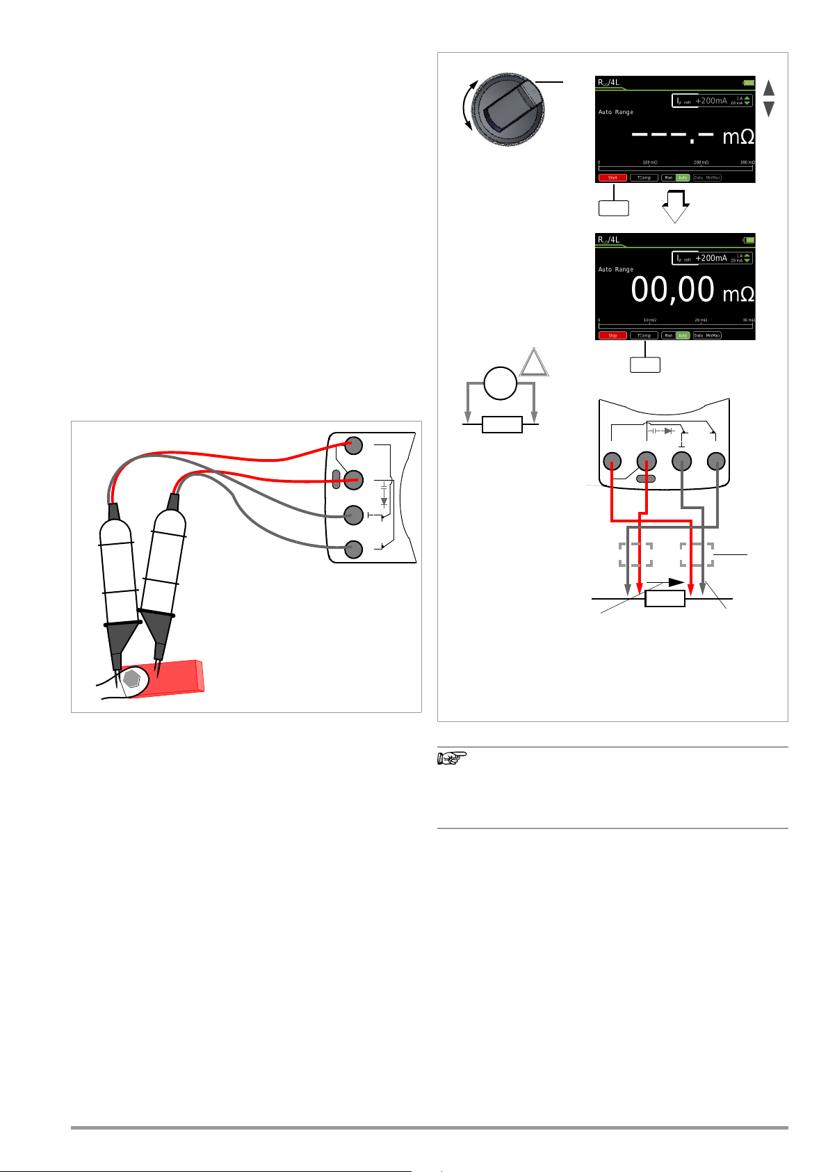
6.14 Milliohm Measurement – m/4 (4-wire measurement)
Note
S– A
V
Tem p
m/4
COIL
S+
Red
Black
Milliohm measurements at busbars,
welding seems, coils with up to roughly
1 H etc. with the KC27 Kelvin Probe
(or KC4 Kelvin clip)
If possible, tips which are not spring-loaded
should be aligned inwardly to the DUT
because they’re connected via the red plugs
labeled S
+
and S– (sense).
Red
Black
R
x
0V!
!
300 m/3 /30
Measuring ranges:
+20 mA/+200 mA/+2 A
Test current:
m
4
Measurement
KC27 or KC4
Voltage Drop
Measuring Current
Note:
If KC27 or KC4 is
used, the red plug is
always connected to
S+ or S–.
m: 0.001 m 30
Overall measuring range:
Start
TComp
Cables,
S– A
V
Tem p
m/4
COIL
S+
R
x
+–
6.14.1 Compensation of Cable Resistance
Electrical resistance is a dipole which can generally only be measured using two poles. This is accomplished by directing a measuring current of predetermined magnitude through the device
under test and measuring the resultant voltage drop. The respective resistance value is derived from the quotient of these two values.
The two points between which voltage is measured are decisive
as regards the results of the measurement. All resistances
between these two points add to the measured resistance value.
These include contact resistance, as well as cable resistance. If a
very low resistance value needs to be measured, for example
contact resistance at a contactor with a value of only a few milliohms, the points between which voltage is measured must be
moved out of the measuring instrument and positioned as closely
as possible to the device under test. For this reason, the measuring instrument is equipped with separate jacks for current feed
and voltage measurement. This type of 4-pole connection is
known as connection according to Kelvin.
KC4 Kelvin clips and KC27 Kelvin probes (available as accessories) allow for simple, correct connection.
Measurement with the KC27 Kelvin Probe
6.14.2 Thermovoltage Compensation
Thermovoltages which occur as a result of material and temperature differences may distort measurement results. For this reason,
the instrument is equipped with automatic thermal voltage compensation within the relevant ranges.
If measuring current is interrupted during the 4-L-m
measurement, or if the fuse blows,
“LEADS OPEN” blinks at the display.
Refer to chapter 9.3 in the event of a blown fuse.
GMC-I Messtechnik GmbH 37
Page 38

6.14.3 Milliohm Measurement with 200 mA or 20 mA DC [m]
➭ Make sure that the device under test is voltage-free (see
Chapter 6.6.4). Interference voltages distort measurement results!
➭ Set the rotary switch to “m/4”.
➭ Select desired test current Ip set with the ▲▼ scroll keys.
➭ If applicable, select the desired measuring range using the
Man / Auto key: 30 m, 300 m, 3 (Ip set = +200 mA) or 30
(Ip set = +20mA).
➭ Connect the device under test as shown.
➭ Activate the measurement by pressing the Start softkey.
➭ If required, activate thermovoltage correction (see description
below).
➭ Press the Stop softkey in order to end the measurement.
KC4 Kelvin clips and KC27 Kelvin probes (available as accesso-
ries) allow for simple, correct connection.
Resistance at the current jacks should amount to <5.
This measuring method is suitable for resistances with induc-
tances of up to 1 H.
Thermovoltage Correction in the 30/300 m Range
➭ Connect the measurement cables and press the TComp soft-
key in order to measure thermovoltage.
Wait until the measured value has settled in. This may take
several seconds, depending upon inductivity. After the measured value has settled in, press the Save softkey. The TComp
softkey changes color from black to green. All future measurement results will be corrected based upon the previously measured thermovoltage value.
Thermovoltage can also be measured during a running measurement after pressing the Start softkey.
Use the same procedure as described above.
6.14.4 Milliohm Measurement with 1 A Pulsating Measuring Current
(automatic thermovoltage correction at 3
➭ Make sure that the device under test is voltage-free (see
Chapter 6.6.4). Interference voltages distort measurement results!
➭ Set the rotary switch to “m/4”.
➭ Connect the device under test as shown.
KC4 Kelvin clips and KC27 Kelvin probes (available as accessories) allow for simple, correct connection.
Resistance at the current jacks should amount to < 0.5 .
➭ If applicable, select the desired measuring range using the
Man / Auto key: 3m (Ip set = +1A), (30 m or 300 m
(Ip set = +1A)
➭ Connect the device under test as shown.
Thermovoltage is compensated automatically.
➭ Activate the measurement by pressing the Start softkey.
➭ Press the Stop softkey in order to end the measurement.
The 1 A setting for test current can be protected with a password.
If applicable, you’ll be prompted to enter the valid password.
See also chapter 4.4.6 on page 10, “Changing the Password”,
and chapter 6.1 on page 20, “Enabling Parameter Changes”.
300 m
)
Thermovoltage Correction in the 30/300 m Range
➭ First of all press the Start softkey and then the TComp softkey in
order to measure thermovoltage. The TComp softkey changes
color from black to green. Wait until the measured value has
settled in. This may take several seconds, depending upon inductivity. All future measurement results will be corrected
based upon the previously measured thermovoltage value.
Measurements at Inductive Devices
Coils, for example in motors, choke ballasts and contactors, are
highly inductive. Changes in current at inductive devices, including those caused by switching the milliohmmeter on and off or
changing the measuring range, result in a corresponding voltage
change. These changes may be of significant magnitude, and
may result in arcing under unfavorable conditions. The milliohmmeter is protected against arcing by means of suitable voltage
arrestors.
38 GMC-I Messtechnik GmbH
Page 39

6.15 Current Measurement
F1
Notes Regarding Current Measurement
• The multimeter may only be operated with installed rechargeable
battery pack or mains module. Dangerous currents are otherwise not
indicated, and the instrument may be damaged.
• Set up the measuring circuit in a mechanically secure fashion,
and secure it against inadvertent breaks. Select conductor
cross-sections and lay out connections such that they do not
overheat.
• In the case of current greater than 1.1 A, “OL” appears at the
display.
• The input for the current measuring range is equipped with a
fuse link. Maximum permissible voltage for the measuring circuit (= rated voltage of the fuse) is 1000 V AC/DC.
Use specified fuses only! The fuse must have a breaking capac-
ity of at least 30 kA.
• If the fuse for the active measuring range
has blown, the blown fuse symbol appears
at the digital display.
• If a fuse should blow, eliminate the cause of
overload before placing the instrument back into service!
• Fuse replacement is described in Chapter 9.3.
• Be absolutely certain that the measuring ranges are not overloaded beyond their allowable capacities. Limit values are
included in chapter 8, “Characteristic Values”, in the table entitled “Measuring Functions and Measuring Ranges” in the
“Overload Capacity” column.
GMC-I Messtechnik GmbH 39
Page 40

6.15.1 Direct and Pulsating Current Measurement, Direct Connec-
S– A
V
Tem p
m/4
COIL
S+
Func
Func
ADC
A(AC+DC)
AAC
Hz
Func
A
A
~
R
x
~
R
x
1
3
2
A: 10 nA ... 1 A
A: 10 nA ... 1 A
5 ranges:
A DC Measuring Range:
300 A / 3 mA / 30 mA /
300 mA / 1 A
A (AC+DC) measuring range:
5 ranges:
300 A / 3 mA / 30 mA /
300 mA / 1 A
Func
Current
Zero
Zero
tion, – A DC and A (AC+DC)
➭ First disconnect supply power from the measuring circuit or
the power consumer (1), and discharge any capacitors.
➭ Set the rotary switch to A (A ).
➭ Repeatedly press the Func softkey until the desired measuring
function is displayed.
➭ If necessary, conduct zero balancing by pressing the Zero
softkey (see description below).
➭ Safely connect the measuring instrument (without contact re-
sistance) in series to the power consumer (2) as shown.
➭ Switch supply power to the measuring circuit back on (3).
➭ Read the display. Make a note of the measured value if the in-
strument is not being operated in the memory mode or the
transmission mode.
➭ Disconnect supply power from the measuring circuit or the
power consumer (1) once again, and discharge any capacitors.
➭ Remove the test probes from the measuring point and return
the measuring circuit to its normal condition.
Improving Accuracy by means of Zero Balancing – Zero
The currently measured current value can be subtracted from
future measurements in all measuring ranges.
➭ Press the Zero softkey.
➭ The value ascertained for Zero is saved and appears above the
measurement display. Automatic compensation is implemented for future measurements.
➭ The value for Zero is retained when the instrument is switched
to a different measuring function. The correction or offset value
is deleted by pressing Zero once again, or when the instrument
is switched off. The value is cleared from the display.
40 GMC-I Messtechnik GmbH
Page 41

6.15.2 Alternating Current and Frequency Measurement, Direct
S– A
V
Tem p
m/4
COIL
S+
A
A
~
R
x
~
R
x
1
3
2
!
I > 1 A
A~: 10 nA ... 1 A
5 ranges:
300 A / 3 mA / 30 mA /
300 mA / 1 A
A AC measuring range:
Current
300 Hz / 3 kHz /
4 ranges:
30 kHz / 300 kHz
Hz: 0.01 ... 300 kHz
Hz measuring range:
Func
Func
ADC
A(AC+DC)
AAC
Hz
Func
FuncZero
Connection, – AAC and Hz
➭ First disconnect supply power from the measuring circuit or
the power consumer (1), and discharge any capacitors.
➭ Set the rotary switch to A (A ).
➭ Repeatedly press the Func softkey until the desired measuring
function is displayed.
➭ If necessary, conduct zero balancing for AAC by pressing the
Zero softkey (see description below).
➭ Safely connect the measuring instrument (without contact re-
sistance) in series to the power consumer as shown.
➭ Switch supply power to the measuring circuit back on (3).
➭ Read the display. Make a note of the measured value if the in-
strument is not being operated in the memory mode or the
transmission mode.
➭ Disconnect supply power from the measuring circuit or the
power consumer (1) once again, and discharge any capacitors.
➭ Remove the test probes from the measuring point and return
the measuring circuit to its normal condition.
Improving Accuracy by means of Zero Balancing – Zero
The currently measured current value can be subtracted from
future measurements in all measuring ranges.
➭ Press the Zero softkey.
➭ The value ascertained for Zero is saved and appears above the
measurement display. Automatic compensation is implemented for future measurements.
➭ The value for Zero is retained when the instrument is switched
to a different measuring function. The correction or offset value
is deleted by pressing Zero once again, or when the instrument
is switched off. The value is cleared from the display.
GMC-I Messtechnik GmbH 41
Page 42

6.15.3 Direct and Pulsating Current Measurement with Current
MENU
OKOKESC
S– A
V
Tem p
m/4
COIL
S+
V
V
mA/A: See table
Measuring ranges:
Func
Func
ADC
A(AC+DC)
Zero
Zero
~
R
x
Current
R
i
Ri ~ 9 M
mA/A: See table
Measuring ranges:
Clip Off
Clamp Sensor – ADC and A (AC+DC)
Voltage/Current Transformer Output
When a current clamp sensor is connected to the multimeter
(V input), all current displays appear with the correct value in
accordance with the selected transformation ratio. The only prerequisite is that the current sensor is equipped with at least one of
the below listed transformation ratios, and that the ratio has been
previously selected in the following menu (Clip Off).
➭ Set the rotary switch to V or V .
➭ Press the MENU key.
➭ Press the “Setup for currently selected measurement” softkey.
➭ Set the Clip parameter to the desired transformation ratio (the
same ratio as selected at the current clamp sensor) as described below in the current clamp settings menu or select the
desired transformation ratio with the scroll keys ▲▼.
➭ The display is returned to the measurement view by pressing
the ESC key three times.
➭ Repeatedly press the Func softkey until the desired measuring
function is displayed.
➭ Connect the current clamp sensor’s measurement cables as
shown.
➭ If necessary, conduct zero balancing by pressing the Zero key
(see description below).
Current Clamp Setup Menu
>
Setup for currently selected measurement
Off / 1:1 / 1:10 / 1:100 / 1:1000
3 x > Measurement View
Clip
Tra ns fo rma tion Ratio
1:1
1mV/1mA
1:10 AM
1mV/10mA
1:100
1mV/100mA
1:1000
1mV/1A
The maximum allowable operating voltage is equal to the nominal
voltage of the current transformer.
value, additional error resulting from the current clamp sensor must
also be taken into consideration
(default setting: Clip = Off = voltage display).
Measuring Ranges Clamp Type
300 mV 3 V 30 V
300.0 mA 3.000 A 30.00 A
3.000 A 30.00 A 300.0 A CP30
30.00 A 300.0 A 3,000 kA
300.0 A 3,000 kA 30.00 kA
CP330/1100/
1800
CP330/1100/
1800
When reading the measured
Improving Accuracy by means of Zero Balancing – Zero
The currently measured current value can be subtracted from
future measurements in all measuring ranges.
➭ Press the Zero softkey.
➭ The value ascertained for Zero is saved and appears above the
measurement display. Automatic compensation is implemented for future measurements.
➭ The correction or offset value is deleted by pressing Zero, by
changing to another measuring function or by switching the instrument off. The value is cleared from the display.
42 GMC-I Messtechnik GmbH
Page 43

6.15.4 Alternating Current Measurement with Current Clamp Sen-
MENUOKOK
ESC
S– A
V
Tem p
m/4
COIL
S+
Func
Func
AAC
Hz (A)
V~
Hz
~
R
x
Current
R
i
Ri ~ 9 M
mA/A: See table
Measuring ranges:
Measuring ranges:
Hz: 300 Hz/3 kHz/
Hz: 30 kHz/300 kHz
Clip Off
Zero
sor – AAC and Hz
Voltage/Current Transformer Output
When a current clamp sensor is connected to the multimeter
(V input), all current displays appear with the correct value in
accordance with the selected transformation ratio. The only prerequisite is that the current sensor is equipped with at least one of
the below listed transformation ratios, and that the ratio has been
previously selected in the following menu (Clip Off).
➭ Set the rotary switch to V~ or Hz.
➭ Press the MENU key.
➭ Press the “Setup for currently selected measurement” softkey.
➭ Set the Clip parameter to the desired transformation ratio (the
same ratio as selected at the current clamp sensor) as described below in the current clamp settings menu or select the
desired transformation ratio with the scroll keys ▲▼.
➭ The display is returned to the measurement view by pressing
the ESC key three times.
➭ Repeatedly press the Func softkey until the desired measuring
function is displayed.
➭ Connect the current clamp sensor’s measurement cables as
shown.
➭ If necessary, conduct zero balancing by pressing the Zero key
(see description below).
➭ The correction or offset value is deleted by pressing Zero, by
changing to another measuring function or by switching the instrument off. The value is cleared from the display.
Current Clamp Setup Menu
Tra ns fo rma tion Ratio
1mV/1mA
1:10 AM
1mV/10mA
1mV/100mA
1:1000
1mV/1A
The maximum allowable operating voltage is equal to the nominal
voltage of the current transformer.
value, additional error resulting from the current clamp sensor must
also be taken into consideration
(default setting: Clip = Off = voltage display).
1:1
1:100
>
Setup for currently selected measurement
Off / 1:1 / 1:10 / 1:100 / 1:1000
Clip
3 x > Measurement View
Measuring Ranges Clamp Type
300 mV 3 V 30 V
METRAFLEX 300M
300.0 mA 3.000 A 30.00 A
3.000 A 30.00 A 300.0 A
30.00 A 300.0 A 3,000 kA
300.0 A 3,000 kA 30.00 kA
WZ12C,
Z3512A
CP30,
METRAFLEX
3000/300M
WZ11B, WZ12B,
Z3512A
CP330/1100/1800
METRAFLEX
3000/300M,
WZ11B,
Z3512A
CP330/1100/1800
METRAFLEX 3000
WZ12C,
Z3512A
When reading the measured
Improving Accuracy by means of Zero Balancing – Zero
The currently measured current value can be subtracted from
future measurements in all measuring ranges.
➭ Press the Zero softkey.
➭ The value ascertained for Zero is saved and appears above the
measurement display. Automatic compensation is implemented for future measurements.
GMC-I Messtechnik GmbH 43
Page 44

6.16 Measuring Sequences
If the same sequence of single measurements will be run frequently (one after the other with subsequent report generation),
it’s advisable to make use of measuring sequences.
Up to 10 measuring steps can be created for each measuring
sequence. The measuring steps can include measuring functions
as well as measuring instructions.
Automatic measuring sequences can be conducted in all rotary
switch positions except for OFF.
Measuring sequences can also be created at a PC and transferred to the multimeter with the help of IZYTRONIQ software.
Creating a New Measuring Sequence
➭ Select any rotary switch position other than “OFF”.
➭ Press the “MENU” key.
➭ Press the “Edit/delete new measuring sequence” softkey. The
sequence’s steps are displayed.
➭ First of all assign a name to the sequence to be created.
➭ Press the “SEQ Name” softkey to this end.
➭ Enter a name using the keyboard which appears at the display
as described on page 10.
➭ Acknowledge your entry by pressing the “Enter” softkey.
The sequence’s steps are displayed once again.
➭ You can insert a measuring step with any desired measuring
function after pressing the “Ins Function” softkey.
➭ Press the “Ins Function” key, select the desired function with
the rotary switch and acknowledge your selection by pressing
the STORE key.
➭ The “Information > Sequence draft > Accept function with
STORE key” window is displayed once every 5 seconds for a
duration of 1 second.
➭ If you would like to insert measuring instructions, press the
“Ins Check” softkey.
➭ You can enter a comment for each measuring step (measur-
ing function or measuring instructions), which appears at the
display during the measuring sequence, for example “measure voltage at point XY”. Press the “Comment” softkey to this
end.
➭ Enter a text using the keyboard which appears at the display
as described on page 10.
➭ Acknowledge your entry by pressing the “Enter” softkey.
The sequence’s steps are displayed once again.
➭ Individual measuring steps can be removed by selecting the
desired step with the cursor and then pressing the “Delete”
softkey.
44 GMC-I Messtechnik GmbH
Page 45

Running a Measuring Sequence
➭ Select any rotary switch position other than “OFF”.
➭ Press the “MENU” key.
➭ Press the “Start sequence” softkey. General information con-
cerning the measuring sequence is displayed at first:
STORE: Press the STORE key at the multimeter or on the Z270S
probe at the end of a measuring step in order to save one or
more measured values.
OK: Press the OK key at the end of a measuring step in order to
start the next measuring step.
ESC: The sequence can be interrupted by pressing the ESC
key. Values saved up to this point in time are stored under a
name.
➭ Press the “Start” softkey with red background.
➭ Information concerning the pending measuring step is dis-
played first of all: Sequence step 1/x: Measuring function XY
and measuring instructions if applicable.
➭ Acknowledge this information by pressing the “OK” softkey
with green background.
➭ A warning appears prompting you to select the rotary switch
position which is required for the respective measuring function.
➭ The active sequence is displayed in the status bar by means
of the SEQ symbol.
➭ The respective measuring function is started automatically if
as a voltage measurement is involved. For other measuring
functions, the “Start” softkey for the respective measuring
function must first be pressed, and subsequently the “Stop”
softkey.
➭ Press the STORE key in order to save the measured value
➭ Press the OK key in order to start the next measuring step.
➭ If the last measuring step of the measuring sequence is ended
by pressing the “OK” softkey, the first four measuring steps or
measuring functions are displayed and stored with value, date
and time. Press the ▼ scroll key in order to display further
measuring steps.
➭ The measuring sequence is ended by pressing the “STORE”
softkey. A corresponding message appears.
Overview of the Meanings of Softkeys and Hard Keys
Key Meaning
Softkeys
SEQ Name Enter or change the name of a measuring sequence*
Ins Function Insert a measuring step above the selected line with measuring function
Ins Check Insert a measuring step above the selected line with measuring instruc-
tions
Delete Delete the measuring step which was previously selected with the cursor
Comment Enter a comment regarding the selected measuring step via the key-
board*
Start Start the measuring sequence
Start the measurement
Stop Stop the measurement
End the measuring sequence
OK Softkey: Acknowledge instructions during the measuring sequence
Hard Keys
▲▼ Sequence creation: Select measuring step (1 to 10)
STORE Sequence creation: Transfer the measuring function to the sequence
Sequence run: Save the measured value for the current measuring step
by pressing the hard key at the multimeter or on the Z270S probe
OK Sequence run: End the measuring step
* Description of keyboard operation for entering text (see page 10)
GMC-I Messtechnik GmbH 45
Page 46

7 Interface Operation
Warning!
!
Attention!
!
7.1 Bluetooth Interface
In the case of the METRAHIT IM XTRA BT (M273D) and the METRAHIT
IM E-DRIVE BT (M274B), wireless transmission is possible via Blue-
tooth to a PC, as well as to a smartphone or a tablet PC
(Android).
If you adjust the settings in a METRAHIT IM XTRA BT or
METRAHIT IM E-DRIVE BT via Bluetooth, please make sure
that the Bluetooth connection has been established with
the device to be configured rather than with another
METRAHIT IM device that might also be located nearby.
Apart from that, we recommend using an individual
device PIN in order to prevent third parties from having
access to your devices.
Activating the Interface
Interface > Bluetooth > On/Off in the General Setup menu
Configuring Interface Parameters
Interface > PIN > 1234 in the General Setup menu
7.2 WiFi Interface
In the case of the METRAHIT IM XTRA WiFi (M273W) and the
METRAHIT IM E-DRIVE WiFi (M274W), WiFi transmission is possible
to a PC, as well as to a smartphone or a tablet PC (Android).
The METRALOG app can be obtained from the
Google Play Store (see QR code to the right) and
installed to your smartphone or tablet PC (operating systems as of Android 2.3.3).
Any and all liability is excluded for possible software errors, in particular also resulting from interaction with
other applications.
Condensed Instructions
1 Tap the app logo in order to start the program.
2 Select METRAHIT IM XTRA BT or METRAHIT IM E-DRIVE BT from the
list of receivable Bluetooth devices. The following message
appears: “Connecting to measuring instrument via Bluetooth”.
3 In order to enable wireless connection, enter the same PIN
which you also entered under the multimeter’s PIN interface
parameter. After connection has been successfully established, an analog display appears and “Measurement completed” appears at the bottom right.
4 You can switch back and forth amongst digital display, Y(t)
measured value curve and analog display in the footer at the
left-hand side.
5 You can start or stop a measured value recording by tapping
the REC symbol.
6 You can switch the display to the measured value logger over-
view by tapping the magnifying glass icon in the footer at the
right-hand side Measuring intervals can be selected here, in
order to display them graphically or transmit them.
Activating the Interface
Interface > WiFi > On/Off in the General Setup menu
USB-Bluetooth Adapter for PC
The following Bluetooth adapters for communication between the
METRAHIT IM XTRA BT / METRAHIT IM E-DRIVE BT and the PC have
already been successfully tested: Belkin F8T016NG, LOGI LINK
BT0007 and SITECOM CN-524 V2 001.
Bluetooth adapters from other manufacturers should meet at
least the following technical requirements:
Bluetooth 4.2 + EDR, class 2
Terminal Program for a PC
Measured values received via a Bluetooth adapter can be displayed and evaluated at a terminal program.
METRALOG App for Smartphone and Tablet PC
If you use a smartphone or a tablet PC with the Android operating
system and a Bluetooth interface, our METRALOG app provides the
following functions in combination with the METRAHIT IM XTRA BT /
METRAHIT IM E-DRIVE BT TRMS digital multimeter:
• Display of received multimeter measured values as:
Digital or analog values, measured value curve Y(t), measured
value logger
• Recording of measuring operations
• Transmission of logs via wireless services and network services
• Acoustic warning in the event that wireless connection is interrupted
• Trigger in the event of exceeding or falling short of an adjustable limit value
• SMS and/or acoustic warning in the case of trigger events
46 GMC-I Messtechnik GmbH
Page 47

8 Characteristic Values
Mea-
suring
Func-
tion
(input)
Measuring Range
Resolution at
Upper Range Limit
30,000 3,000
Input impedance
300 mV 10 V9M 9M // < 50 pF 0.15 + 10
3 V 100 V9M 9M // < 50 pF 0.15 + 10
V
30 V 1 mV 9 M 9M // < 50 pF 0.15 + 10
300 V 10 mV 9 M 9M // < 50 pF 0.2 + 20
1000 V 100 mV 9 M 9M // < 50 pF 0.2 + 20
Voltage drop at approx. range limit
300 A 10 nA 70 mV 0.25 + 10 1+ 30
3 mA 100 nA 165 mV
A
30 mA 1 A 190 mV
300 mA 10 A 450 mV
1 A 100 A1.2V 1 A 5 min.
A
@ V
/
AC
V
DC
Factor: 1:1/10/100/1000
0.3/3/30/300 A 300 mV
3, 30, 300, 3 k A
Measuring input Input impedance ~
3V Plus current transformer clamp error 1000 V Max. 10 s
Voltage measurement input approx. 9 M
( V socket)
Open-circuit voltage
m @
1A
pulse
(4-wire)
m@
200 mA
(4-wire)
m@
20 mA (4-
wire)
2-wire
R
Lo
EN61557
3m 0.001 m 2.8 … 3.8 V 1 A 1.0 +20
30 m 0.01 m 2.8 … 3.8 V 1 A
300 m 0.1 m 2.8 … 3.8 V 1 A
30 m 0.01 m > 4 V 200 mA
300 m 0.1 m > 4 V 200 mA
3 1 m > 4 V 200 mA
30 10 m > 4 V 20 mA 0.5 + 7
@ 200 mA: 3 1 m > 4 V 200 mA 2.5 +10
@ 20 mA: 30 10 m > 4 V 20 mA 2.5 +10
300 10 m < 1.4 V Approx. 300 A0.2 + 30
(2-
wire)
3k 100 m < 1.4 V Approx. 100A
30 k 1 < 1.4 V Approx. 10 A 0.15 + 10
300 k 10 < 1.4 V Approx. 1 A 0.15 + 10
3M 100 < 1.4 V Approx. 0.2 A0.5 + 10
30 M 1k < 1.4 V Approx. 0.03A2.0 + 10
300 100m Approx. 3 V
3
4,5 V
1mV Approx. 8 V 0.5 + 2
Discharge resis-
tance
30 nF 10 pF 10 M 0.7 V 1.5 + 10
300 nF 100 pF 1 M 0.7 V 1 + 6
F
3 F 1 nF 100 k 0.7 V 1 + 6
30 F10nF12k 0.7 V 1 + 6
300 F 100 nF 3 k 0.7 V 5 + 6
Hz (V)/
Hz (A)
Hz
(A )
%
RPM
C / F
1
15 ... 45 ... 65 Hz ... 100 kHz sinusoidal. See influence on page 48.
2
At 0 ... + 40 C
3
Display up to 5.1 V, “OL” for higher values.
4
Applies to measurements at film capacitors
5
Lowest measurable frequency for sinusoidal measuring signals symmetrical to the zero point
6
Overload capacity of the voltage measurement input:
Power limiting: frequency x voltage max. 6 x 10
7
Overload capacity of the current measurement input: see current measuring ranges for maximum
current values
8
Input sensitivity, sinusoidal signal: 10% to 100% of the voltage or current measuring range, restriction in mV measuring range: 30% rdg.
The voltage measuring ranges with max. 10 kHz apply in the A measuring range.
9
Plus sensor deviation
10
With active ZERO function
300 Hz 0.01 Hz
3kHz 0.1Hz
30 kHz 1 Hz
300 kHz 10 Hz 20 Hz
10.0 ... 90.0
10.0 ... 90.0 > 1 kHz ... 4 kHz 0.2% MR/kHz + 8 d
5.0 ... 95.0
0.1%
15.0 ... 85.0 > 1 kHz ... 4 kHz 0.2% MR/kHz + 8 d
3 V AC
30 V AC
Resolution Voltage MR
13
30 … 30,000 1 RPM
– 200 ...
Pt 100
+850 C
K
(NiCr-Ni)
– 200 ...
+850 C
– 250 ...
+1372 C
0.1 C
6
V x Hz @ U > 100 V
Intrinsic Uncertainty at Reference Conditions
30,000 3,000 30,000 30,000
~ /
10
0.15 + 10 0,5 + 30
10
0.15 + 10
Meas. current at
range limit
Approx. 1 mAconst.
U
0 max
5
f
min
1 Hz
Frequency MR (... % MR + ... d)
15 Hz ... 1 kHz 0.2% rdg. + 8 d 1000 V
15 Hz ... 1 kHz 0.2% rdg. + 8 d
11
12
13
14
15
16)
(... % rdg. + ... d)
3,000
0.5 + 7
16
0.5 + 7
10
10
10
10
0.15 + 10
10
1 + 5
(... % rdg. + ... d)
4 10
4
4
4
4
(... % rdg. + ... d)
8
0.05 + 5
(... % rdg. + ... K)
0.5% + 1.5
0.5% + 1.5
1% + 5
Accuracy applies as of 1% MR. Values < 50 digits are suppressed at the zero point due to the
TRMS transformer.
10 minute cool-down period
Required signal range: 30% to 100% of the voltage measuring range
The integrated FF1A/1000V fuse blows in the event of overloading
The integrated FF0.315A/1000V fuse blows in the event of overloading
For measuring range 30 m and 300 m with function TComp active
1, 11
~
0.5 + 30 1.0 + 30
1, 11
~
10)
1.0 + 30 d
10)
1, 11
0.5 + 30 d 1.0 + 30 d
9
1, 11
1, 11
1, 11
Key: d = digit(s), MR = measuring range, rdg. = reading (measured
value)
Overload
Capacity
Value Time
1000 V
DC
AC
RMS
Sinusoi-
dal
6
0.3 A Cont.
Measurement input
14
±0.6V
14
±0.6V
14
±0.6V
15
±0.6V
1000 V
DC
AC
RMS
Max. 10 s
Sinusoi-
dal
1000 V
DC
AC
Max. 10 s
RMS
Sinusoi-
dal
Hz (V) 6:
Hz(A )6:
1000 V
Max. 10 s
7
Hz (A):
DC AC
RMS
Sinusoidal
6
1000 V
DC/AC
Max. 10 s Pt 1000
RMS
Sinusoidal
2(... % rdg. + ... d)
Cont.
6
Cont.
Cont.
Cont.
Cont.
Cont.
GMC-I Messtechnik GmbH 47
Page 48

Insulation Measurement
Measuring Range Resolution
3 ... 1000 V
1
1V
300 k 0.1 k
3 M 1k
30 M 10 k
300 M 100 k
3000 M 1M
1
TRMS interference voltage measurement (V
frequency response width: > 65 Hz ... 500 Hz, accuracy: 3% + 30 digits
Measuring
Function
U
interference
M
M
@UISO
@UISO
Nom.
Open-
Voltage
Circuit
Voltage
U
N
U
max.
/
o
— —— —
50
1.2 x
100
U
250,
500 V
1000 V
INS
1.12x
U
INS
Nominal Voltage
U
ISO
Ri=1M
50/100/250/500 V
50/100/250/500/1000 V
50/100/250/500/1000 V
50/100/250/500/1000 V
250, 500, 1000 V
AC+DC
Nom.
Short-
Cur-
Circuit
rent I
Cur-
N
rent I
) with 1 M input resistance,
Acoustic
Signal
k
U > 1000
1.0 mA < 1.4mAU > 1000 V 1000 V 10 s
Intrinsic Uncer-
tainty at Reference
Overload Capacity
for
Value Time
1000 V
V
Conditions
(% rdg. + d)
3 + 3
2 + 10
2 + 10
2 + 10
5 + 10
5 + 10
Short-circuited coil test (only with optional COIL adapter)
Measuring Range Resolution
0.3 V ... 1000 V
1
10.0 ... 30.9 μs 0.1 [μs]
31 ... 250 μs 1 [μs]
1
TRMS interference voltage measurement (V
frequency response width: > 65 Hz ... 500 Hz, accuracy: 3% + 30 digits
Nominal Voltage
U
ISO
Ri=1M
1000 V
) with 1 M input resistance,
AC+DC
Intrinsic Uncer-
tainty at Reference
Conditions
(% rdg. + d)
3 + 30 > 100 digits
10 + 5 digits
Short-circuited coil test within an inductance range of:
10 μH to 50 mH @ 100 Hz
Internal Clock
Time format DD.MM.YYYY hh:mm:ss
Resolution 0.1 s (measured values timestamp)
Accuracy 1 minute per month
Temperature influence
50 ppm/K
Reference Conditions
Ambient temperature + 23 C 2K
Relative humidity 40% 75%
Measured quantity frequency
Measured quantity waveform
Supply voltage 4.0 V 0.1 V
45 Hz 65 Hz
Sinusoidal
Continu-
ous
Frequency Influence for VAC V
Frequency Range
15 Hz ... 45 Hz 2 + 30 2 + 30 2 + 30
> 65 Hz ... 1 kHz 0.5 + 30 0.5 + 30 1 + 30
> 1 kHz ... 10 kHz 2 + 30 1.5 + 30 10 + 30
> 10 kHz ... 20 kHz 3 + 30 1.5 + 30 –
> 20 kHz ... 50 kHz 3 + 30 5 + 30 –
> 50 kHz ... 100 kHz 10 + 30 10 + 30 –
1
For sinusoidal input signals > 10% to 100% of the range (mV range: as 30% of the range), at 1% to 10%
of the range: f < 50 kHz, intrinsic error increased by 0.2% of the upper range limit.
2
Overload capacity of the voltage measurement input:
Power limiting: frequency x voltage max. 6 x 10
300 mV range
± (... % rdg. + ... digits)
Frequency Influence for IAC / I
Frequency Range
15 Hz ... 45 Hz 2 + 30 2 + 30
> 65 Hz ... 1 kHz 1 + 30 1 + 30
> 1 kHz ... 2 kHz 1 + 30 1 + 30
> 2 kHz ... 5kHz 1 + 30 3 + 30
> 5 kHz ... 10 kHz 5 + 30 5 + 30
1
For sinusoidal input signals > 10% to 100% of the range.
Influencing
Quantity
Crest Factor CF
1
Except for sinusoidal waveform
Influencing
Quantity
Relative
Atmospheric
Humidity
Battery Voltage 3.6 ... 4.2 V Ditto
Influencing
Quantity
Common Mode
Interference
Voltage
Series Mode
Interference
Voltage
Interference quantity max. 1000 V V > 90 dB
Interference quantity max. 1000 V
respective nominal value of the measuring
range,
Interference quantity max. 1000 V V > 50 dB
300 A to 300 mA
± (... % rdg. + ... digits)
Sphere of
Influence
1 ... 3
> 3 ... 5 3% rdg.
Sphere of
Influence
75%
3 days
instrument off
Sphere of Influence
50 Hz ... 60 Hz sinusoidal
Interference quantity: V ,
max. 1000 V , 50 Hz ... 60 Hz
sinusoidal
Voltage Ranges
AC+DC
Deviation
3 V, 30 V, 300 V range
± (... % rdg. + ... digits)
6
V x Hz @ U > 100 V
Current Measuring Ranges
AC+DC
Influence Error
Measured Qty./
Measuring Range
V, A
1
2
1
1 A range
± (... % rdg. + ... digits)
Influence Error
1% rdg.
Measured Qty. Influence Error
V, A, , F, Hz, C 1 x intrinsic uncertainty
Included in intrinsic uncer-
Measured Qty./
Measuring Range
3 V , > 90 dB
30, 300 V > 150 dB
1000 V > 150 dB
V> 50dB
1000 V range
± (... % rdg.)
tainty
Damping
Response Time (after manual range selection)
2
1
Influencing Quantities and Influence Error
Influencing
Quantity
Tem p er at ur e
1
With zero balancing
Sphere of
Influence
0 C ... +21 C
and
+25 C... +40 C
Measured Qty./
Measuring Range
V 0.2 + 5
V 0.4 + 5
300 ... 3 M 0.5 + 5
30 M 1 + 5
mA/A 0.5 + 5
mA/A 0.8 + 5
30 nF ... 300 F2 + 5
C/F (Pt100/Pt1000) 0.5 + 5
1
Hz 0.2 + 5
Influence Error
(...% rdg. + ... d)/10 K
Measured Qty./
Measuring Range
V, V
A, A
300 ... 3 M 2s
30 M,
M
@UISO
Continuity < 50 ms
C (Pt 100) Max. 3 s
30 nF ... 300 FMax. 5s
>10 Hz 1.5 s
Response Time
Digital Display
1.5 s
Max. 5 s
1.5 s
Jump Function
of the Measured Quantity
From 0 to 80%
of upper range limit value
From to 50%
of upper range limit value
From 0 to 50%
of upper range limit value
48 GMC-I Messtechnik GmbH
Page 49

Display
Power Supply
TFT color graphic display (55 x 36 mm) with analog and digital
display including unit of measure, type of current and various special functions
Background Illumination
Activated background illumination can be regulated by means of
a light sensor.
Analog Bar Graph
Scaling Linear
Polarity display With automatic switching
Sampling rate 40 measurements per second and display
refresh
Digital Measured Value Display
Resolution / char. height
320 x 480 dots, 12 mm
Number of places 31,000 / 3,100
4¾-place in the
V, A, Hz a n d
measuring
functions depending on parameter setting
Overflow display “OL” is displayed for 31,000 digits
or 3100 digits
Polarity display “–” (minus sign) is displayed
if plus pole is connected to “”
Sampling rate 10 and 40 measurements per second
with
the Min-Max function except for the capacitance, frequency and duty cycle measuring
functions
Refresh rate 2 times per second, every 500 ms
Battery pack 3.7 V, 4000 mAh, LiPo
(approx. 25% self-discharging per year)
Service life Approx. 20 hours (without M
surement / R
/ R 4-wire)
Lo
INS
mea-
Battery indicator Battery capacity display via battery sym-
bol: , querying of
momentary charge level via menu function.
Power OFF function
The multimeter is switched off automatically:
– When battery voltage
drops to below approx. 3.6 V
– If none of the keys or the rotary switch
are activated for an adjustable duration of
10 to 59 min. and the multimeter
is not in the continuous operation mode
Rechargeable battery packs can only be recharged externally.
Measuring
Function
1
Times 0.7 for interface operation
Nominal
Voltage U
V 20
V 15
RISO
100 V 1 M 5
100 V 100 k 300
500 V 500 k 60
1000 V 2 M 20
N
DUT Resistance
Service Life
in Hours
Number of Possible
Measurements with Nom.
Current per VDE 0413
1
1
Electromagnetic Compatibility (EMC)
Electrical Safety
Protection category
Measuring category CAT III CAT IV
Nominal voltage 1000 V 600 V
Pollution degree 2
Test voltage 7.4 kV~ per EN 61 010-1:2011/
II per EN 61010-1:2010/VDE 0411-1:2011
VDE 0411-1:2011
Fuse
Current measuring
ranges F1: FF 1 A/1000 V AC/DC;
& 2L m measuring 6.3 x 32 mm
ranges Fuse with breaking capacity of 30 kA at
1000 V AC/DC,
protects the current measurement input in
the 300 A to 1 A ranges
2L mmeasuring ranges
F2: FF 0,315 A / 1000 V
6.3 x 32 mm
Fuse with breaking capacity of 30 kA at
1000 V AC/DC
Interference emission EN 61 326-1:2013 class B
Interference immunity EN 61326-1:2013
Short-term measured value deviation of up to 10% may occur during electromagnetic interference thus reducing the specified operating quality.
Ambient Conditions
Accuracy range 0 C ... +40 C
Operating temperatures
(storage temp. w. battery)
Storage temperatures 25 C ... +70 C (without battery)
Relative humidity 40 ... 75%, no condensation allowed
Elevation To 2000 m
Place of use
10 C ... +50 C
20 C ... +50 C with rubber holster
Indoors, except within specified ambient
conditions
GMC-I Messtechnik GmbH 49
Page 50

Data Interface
Typ e
Bluetooth 4.2
Frequency band 2.402 ... 2.480 GHz
Transmitting power Max. 91 mW
Functions – Query measuring functions
and parameters
– Query momentary measurement data
Internal Measured Value Storage
Memory capacity 64 MBit for approx. 300,000 measured
values with indication of date and time
Mechanical Design
Housing Impact resistant plastic (ABS)
Dimensions 235 x 105 x 56 mm
(without rubber holster)
Weight Approx. 0.7 kg with battery pack
Protection Housing: IP 52
IP XY
st
(1
Protection Against Foreign
digit X)
0 Not protected 0 Not protected
1 50.0 mm 1 Vertically falling droplets
2 12.5 mm 2 Dripping (15 angle)
3 2.5 mm 3 Spraying water
4 1.0 mm 4 Splashing water
5 Dust protected 5 Jet-water
(pressure equalization by means of the
housing)
Table Excerpt Regarding Significance of
IP Codes
Object Ingress
IP XY
(2nd digit Y)
Protection Against Water
Ingress
Applicable Regulations and Standards
IEC 61010-1
DIN EN 61010–1
VDE 0411-1
DIN EN 61326-1
VDE 0843-20-1
DIN EN 60529
VDE 0470-1
Safety requirements for electrical equipment for measurement, control and laboratory use – Part 1: General requirements
Electrical equipment for measurement, control and laboratory
use –EMC requirements – Part 1: General requirements
Test instruments and test procedures
– degrees of protection provided by enclosures (IP code)
50 GMC-I Messtechnik GmbH
Page 51

9 Maintenance and Calibration
Note
Attention!
!
Note
Note
Attention!
!
Note
Attention!
!
b
a
a
Press
Tabs
Z
2
7
0
A
/
G
Micro USB 5 V DC, 2 A
Approx. 2 h
7
0
A
Z
2
7
0
A
/
G
Z270L
Z270L
Removing the Battery Pack
Recommendation:
Disconnect the instrument from the measuring circuit
before removing the battery pack or the mains module!
Disconnect the instrument from the measuring circuit before opening the fuse cover in order to replace the fuse!
9.1 Displays – Error Messages
Message Function Meaning
FUSE Current measurement Blown fuse
In all operating modes Battery voltage has fallen below 3.3 V
0L Measurement Indicates overflow
9.2 Battery Pack
Removing the Battery Pack during Periods of Non-Use
The integrated quartz movement draws power from the
battery pack even when the instrument is switched off.
It’s advisable to remove the battery pack before long periods of non-use for this reason (e.g. vacation). This prevents excessive depletion, which may result in damage to
the lithium-ion batteries under unfavorable conditions.
Removing the Battery Pack or Mains Module
Stored measurement data are not lost when the battery
pack or the mains module is removed. The selected
operating parameters remain in memory, although date
and time must be reentered.
End any automatic measured data recordings which are
currently running before removal. Removing the battery
pack or the mains module during storage operations may
cause data loss or corrupt memory.
Recommendation:
Turn the rotary switch to the OFF position and disconnect
the instrument from the measuring circuit before removing the battery pack or the mains module!
➭ Briefly press the two
locking tabs towards
each other at the
same time with
thumb and forefinger, and then release
them again. Pull the
battery pack up and
out as shown in the
figure to the right.
Charging the Battery Pack
➭ Connect the
micro USB port
to the charger.
The charge LED
lights up yellow
during the charging
process. The
charging cable can
be removed as
soon as the charge
LED lights up green
at the end of the
charging process.
Querying the Battery Pack’s Charge Level
Momentary battery capacity can be queried by clicking the Info
item in the General Setup menu:
➭ Press the MENU key to this end.
➭ Then press the General Setup softkey.
➭ Select the Info parameter with the help of the
The “Battery” parameter indicates the battery pack’s charge level
as a percentage.
scroll keys.
Please observe the currently valid safety notes for lithium-Ion batteries!
Installing the Battery Pack
Disconnect the instrument from the measuring circuit be-
If the “ ” symbol appears at the display, the battery pack
should be replaced as soon as possible. You can continue working with the instrument, but reduced measuring accuracy may
result.
fore removing the battery pack for charging!
➭ Push the battery pack back in until resistance is plainly per-
ceptible.
➭ In order to snap the battery back into place, press the two
locking tabs towards each other at the same time with thumb
and forefinger.
➭ Push the battery back into its final position and release the
locking tabs.
GMC-I Messtechnik GmbH 51
Page 52

9.3 Fuse
Attention!
!
Attention!
!
Note
Attention!
!
Testing the Fuse
The fuse is tested automatically:
• When the instrument is switched on with the rotary switch in
the A position
• When the instrument is already on and the rotary switch is turned to
the A position
• In the active current measuring range when voltage is applied
If the fuse is blown or if no fuse has been
inserted the “FUSE” symbol appears at the display. The fuse interrupts the current measuring
ranges. All other measuring ranges remain
functional.
Replacing the Fuse
If a fuse should blow, eliminate the cause of overload before placing the instrument back into service!
Disconnect the instrument from the measuring circuit before opening the fuse cover in order to replace the fuse!
➭ Set the instrument face
down onto the working
surface.
➭ Turn the slotted screw
on the cover with the
fuse symbol counterclockwise.
➭ Lift off the cover and
pry the fuse out using
the flat side of the fuse
cover.
➭ Insert a new fuse. Make
sure that the fuse is
centered, i.e. between
the tabs at the sides.
➭ When replacing the fuse cover, insert the side with the guide
hooks first.
Tighten the screw by turning it clockwise.
➭ Dispose of the blown fuse with the trash.
9.4 Housing Maintenance
No special maintenance is required for the housing. Keep outside
surfaces clean. Use a slightly dampened cloth for cleaning. In particular for the protective rubber surfaces, we recommend a moist,
lint-free microfiber cloth. Avoid the use of cleansers, abrasives or
solvents.
9.5 Measurement Cables
Inspect the measurement cables for mechanical damage at regular intervals.
Even in the case of minimal damage to the test leads, we
recommend sending them to GMC-I Service GmbH
without delay.
9.6 Returns and Environmentally Sound Disposal
The instrument is a category 9 product (monitoring and control
instrument) in accordance with ElektroG (German electrical and
electronic device law). This device is subject to the RoHS directive. Furthermore, we make reference to the fact that the current
status in this regard can be accessed on the Internet at
www.gossenmetrawatt.com by entering the search term WEEE.
We identify our electrical and electronic devices in
accordance with WEEE 2012/19/EU and ElektroG using
the symbol shown at the right per DIN EN 50419.
These devices may not be disposed of with the trash.
Please contact our service department regarding the return of old
devices (see address in Chapter 1.3).
Disposal of the Battery Pack (rechargeable lithium-ion battery)
If the battery pack is no longer usable, it must be disposed of
properly in accordance with valid national directives.
Dispose of the rechargeable battery in accordance with applicable regulations or send it to GMC-I Service GmbH for free disposal (see address in Chapter 1.3).
Use specified fuses only!
If fuses with other blowing characteristics, other current
ratings or other breaking capacities are used, the operator is placed in danger, and protective diodes, resistors
and other components may be damaged.
The use of repaired fuses or short-circuiting the fuse
holder is prohibited.
Testing the Fuse with the Instrument Switched On
After inserting the fuse with the instrument switched on,
the instrument must be switched off briefly and then
switched back on again, or briefly switched to a non-current measuring range and then back to the A measuring
range.
If contact is poor or the fuse is blown, the “FUSE” symbol
appears at the display.
52 GMC-I Messtechnik GmbH
Page 53

9.7 Recalibration
Note
Attention!
!
The measuring tasks performed with your instrument, and the
stressing it’s subjected to, influence aging of its components and
may result in deviation from the specified levels of accuracy.
In the case of strict measuring accuracy requirements, as well as
in the event of use at construction sites with frequent stress due
to transport and considerable temperature fluctuation, we recommend a relatively short calibration interval of once per year. If your
instrument is used primarily in the laboratory and indoors without
considerable climatic or mechanical stressing, a calibration interval of once every 2 to 3 years is sufficient as a rule.
During recalibration* at an accredited calibration laboratory
(DIN EN ISO/IEC 17025), deviations from traceable standards
demonstrated by your measuring instrument are documented.
Ascertained deviations are used to correct display values during
later use of the instrument.
We would be happy to perform DAkkS or factory calibration for
you at our calibration laboratory. Further information is available
on our website:
www.gossenmetrawatt.com ( COMPANY Quality and Certificates DAKKS Calibration Center Calibration Questions and
Answers.
10 Accessories
10.1 General
The extensive accessories available for our measuring instruments are checked for compliance with currently valid safety regulations at regular intervals, and are expanded as required for new
applications. Currently up-to-date accessories which are suitable
for your measuring instrument are listed at the following web
address along with photo, order number, description and,
depending upon the scope of the respective accessory, data
sheet and operating instructions: www.gossenmetrawatt.de (
PRODUCTS Measuring Technology – Portable – Multimeters
Specialized Applications METRAHIT IM XTRA ... Accessories).
10.2 Technical Data for Measurement Cables (included with KS17-2 cable set and Z270S probe)
Electrical Safety
Maximum rated voltage
Measuring category
Maximum rated current 1 A 1 A 16 A
With safety cap attached
Without safety cap
Observe the measuring instrument’s maximum values for electrical
safety!
600 V 1000 V
CAT IV CAT III CAT II
—
——
1000 V
Recalibration of your instrument at regular intervals is essential for
the fulfillment of requirements according to quality management
systems per DIN EN ISO 9001.
Regular calibration of the test instrument should be performed in a calibration laboratory which is accredited per
DIN EN ISO/IEC 17025.
* Examination of the specification, as well as adjustment, are not included
in calibration. However, in the case of our own products, any required
adjustment is performed and adherence to the specification is confirmed.
9.8 Manufacturer’s Guarantee
All METRA HIT digital multimeters and calibration instruments are
guaranteed for a period of 3 years after date of shipment. The
manufacturer’s guarantee covers materials and workmanship.
Damages resulting from use for any other than the intended purpose or operating errors, as well as any and all consequential
damages, are excluded.
The calibration certificate confirms that the product’s specified
technical data were complied with at the point in time of calibration. We guarantee compliance with the specified technical data
within the permissible tolerances for a period of 12 months after
delivery.
Ambient Conditions (EN 61010-031)
Temperature –20 C ... + 50 C
Relative humidity 50 ... 80%
Pollution degree
2
Use of KS17-2 and Z270S
Measurements per DIN EN 61010-031 may only be performed in environments in accordance with measuring
category III with the safety cap attached to the test probe
at the end of the measurement cable.
In order to establish contact inside 4 mm jacks, the safety caps
have to be removed by prying open the snap fastener with a
pointed object (e.g. the other test probe).
GMC-I Messtechnik GmbH 53
Page 54

11 Index
A
Absorption Index Measurement ..........................................................................25
Accessories ......................................................................................................2, 53
Addresses ..............................................................................................................4
Automatic Shutdown
Specifying a Time
AUTO-Range Function .........................................................................................13
..................................................................................... 11
B
Battery Pack
Charge Level Symbols at the Display
Charging ................................................................................................... 51
Disposal .................................................................................................... 52
Installation ................................................................................................. 51
Periods of Non-Use .................................................................................. 51
Querying Charge Level via Menu ............................................................. 51
Removal .................................................................................................... 51
Bluetooth ..............................................................................................................46
........................................................ 7
C
Cable Resistance .................................................................................................33
Calibration Seal ......................................................................................................8
Capacitance Measurement .................................................................................32
Continuity Test .....................................................................................................35
Current Clamp Sensor ...................................................................................42, 43
Current Measurement
Notes ......................................................................................................... 39
D
Data Backup ...........................................................................................................6
Device Returns .....................................................................................................52
Diode Test ............................................................................................................35
Discharge .............................................................................................................21
Discharging ..........................................................................................................24
Duty Cycle Measurement ....................................................................................29
E
Error ......................................................................................................................21
Error Messages ....................................................................................................51
F
Fuse
Replacement ............................................................................................. 52
Test ........................................................................................................... 52
G
Guarantee .............................................................................................................53
I
Included Features ..................................................................................................2
Interface
Bluetooth
WiFi ........................................................................................................... 46
Interference Voltage Detection ............................................................................21
................................................................................................... 46
K
Keyboard for Entering Text ..................................................................................10
M
Maintenance
Housing ..................................................................................................... 52
Manufacturer’s Guarantee ..................................................................................53
Measured Value Storage
Data Function ........................................................................................... 15
Min-Max Values ........................................................................................ 16
Measurement Cables ...........................................................................................53
Measuring Category
Significance
Measuring Range Selection
Automatic .................................................................................................. 13
Manual ...................................................................................................... 13
Memory
Activating the Trigger ............................................................................... 18
Adjusting Recording Time ........................................................................ 17
................................................................................................ 5
Clearing Memory .......................................................................................19
Creating Groups ........................................................................................19
Ending Recording ......................................................................................19
Querying Occupancy .................................................................................19
Setting Hysteresis .....................................................................................18
Setting the Recording Type ......................................................................17
Setting the Sampling Rate ........................................................................17
Start Recording .........................................................................................19
Trigger Mode Operation ............................................................................18
MemoryAdjusting the Trigger Threshold ............................................................18
Milliohm Measurement
2-Wire Measurement ................................................................................36
4-Wire Measurement ................................................................................37
O
Overview
Keys and Connections ................................................................................7
P
Parameter
Adjusting Recording Time
Auto-OFF ...................................................................................................11
Brightness ...................................................................................................9
Change Password .....................................................................................10
Clear Memory ............................................................................................19
Date/Time ....................................................................................................9
Default Settings .........................................................................................11
Display Profile ............................................................................................10
Display Zeros .............................................................................................10
Entering the Reference Temperature .......................................................34
Language .....................................................................................................9
Manual/Measured Reference Temperature .............................................34
Measured Reference Temperature ..........................................................34
Query Memory Occupancy .......................................................................19
Setting the Sampling Period .....................................................................17
Temperature U/M ......................................................................................34
Password
Change ......................................................................................................10
Parameter Changes ..................................................................................20
Polarization Index Measurement .........................................................................26
Product Support ..................................................................................................... 4
Product Support Hotline ........................................................................................ 4
.........................................................................17
R
Recalibration ........................................................................................................ 53
Recalibration Service ....................................................................................... 4, 53
Reference Junction ............................................................................................. 34
Repair and Replacement Parts Service ................................................................ 4
Resistance Measurement ...................................................................................31
Returns
........................................................................................................52
Device
RPM Measurement .............................................................................................. 29
S
Safety Precautions ................................................................................................. 5
Battery Pack ................................................................................................6
General ........................................................................................................5
Scope of Delivery ................................................................................................... 2
Short-Circuited Coil Measurement ..................................................................... 22
Switching the Instrument On
Manual .........................................................................................................9
Symbols
Danger
.........................................................................................................6
Digital Display ..............................................................................................7
Instrument ...................................................................................................8
on the Instrument ........................................................................................8
Rotary Switch Positions ..............................................................................8
User Interface ..............................................................................................8
54 GMC-I Messtechnik GmbH
Page 55

T
Temperature Measurement
With Thermocouples .................................................................................34
Test Sequences ....................................................................................................44
U
Use for Intended Purpose ......................................................................................5
Use of KS17-2 and Z270S ..................................................................................53
V
Voltage Comparator .................................................................................28, 29, 30
Voltage Measurement
Notes .........................................................................................................27
W
WEEE Mark .............................................................................................................8
GMC-I Messtechnik GmbH 55
Page 56

Edited in Germany • Subject to ch ange without notice • PDF version available on the Internet
GMC-I Messtechnik GmbH
Südwestpark 15
90449 Nürnberg
• Germany
Phone: +49-911-8602-111
Fax: +49 911 8602-777
E-mail info@gossenmetrawatt.com
www.gossenmetrawatt.com
 Loading...