

Gossen MetraWatt METRAHIT ENERGY TRMS System Multimeter, METRAHIT ENERGY, METRAHIT ENERGY M249A Operating Instructions Manual
Page 1
METRAHITENERGY
TRMS System Multimeter
Operating Instructions
3-349-576-03
3/9.11
Page 2
2 GMC-I Messtechnik GmbH
Standard Equipment – Contact Persons
Scope of Delivery
1 TRMS system multimeter METRAHIT ENERGY (M249A)
1 KS29 measurement cable set (Z229A)
2 Batteries
1 Condensed operating instructions
1 CD ROM (with operating instructions, data sheet and more)
1 DKD calibration certificate
1 Rubber holster and carrying strap
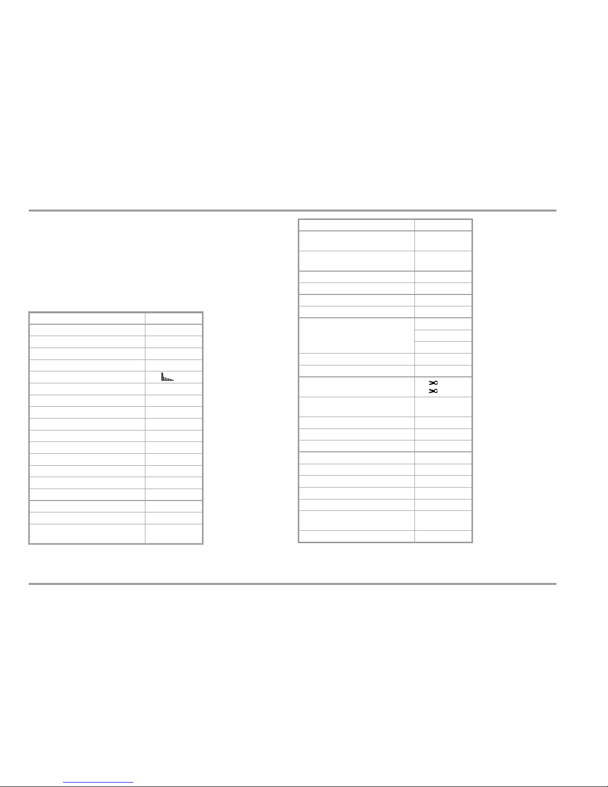
Overview
1
16 Mbit = 2048 kByte = up to 300,000 measured values,
sampling rate adjustable from 0.5 second to 9 hours
Function
Power measurement W (Var, VA, PF)
Energy measurement Wh (varh, VAh)
Events recording DC / AC events
Power disturbance recording PQ
Harmonic analysis V, A
Voltage (Ri 17 M) V
DC
Voltage (Ri 9 M) V
AC
TRMS
Voltage (Ri 9 ... 17 M) V
AC+DC
TRMS
Crest factor (1 CF 11) 3
Frequency in Hz with V
AC
... 300 kHz
Low-pass filter 1 kHz with VAC
Bandwidth for V
AC+DC
or V
AC
100 kHz
Pulse frequency in MHz at 5V
TTL 1 Hz...1 MHz
Duty cycle as % 2.0% ... 98%
Voltage level measurement in dB 3
Resistance
Conductivity nS
Low-resistance measurement
where I
CONST
= 3 mA
R
SL
Continuity test
where I
CONST
= 1 mA
3
Diode test
where I
CONST
= 1 mA
3
Temperature °C/°F with T
C
Type K
Temperature °C/°F R
TD
Pt100/Pt1000
Capacitance in F 3
Cable length in m 3
Current A
DC
AAC TRMS
A
AC+DC
TRMS
Bandwidth for A
AC+DC
or A
AC
10 kHz
Frequency in Hz for A
AC
... 60 kHz
Current clamp measurement with
adjustable transformation ratio
mV / A
mA / A
Relative value measurement
(ref. value measurement) REL
3
Zero point 3
Data logger function
1
(memory) 16 MBit
Min-Max / data hold 3
IR interface (38.4 kBd) 3
Power pack socket 3
Rubber holster 3
Fuse 10 A / 1000 V
Protection
3
IP 52
Measuring Category 600 V CAT III
300 V CAT IV
Calibration DKD
Function
Page 3

GMC-I Messtechnik GmbH 3
Standard Equipment – Contact Persons
Accessories (sensors, plug inserts, adapters, consumable materials)
The accessories available for your instrument are checked for
compliance with currently valid safety regulations at regular intervals, and are amended as required for new applications. Currently
up-to-date accessories which are suitable for your measuring
instrument are listed at the following web address along with
photo, order number, description and, depending upon the
scope of the respective accessory, data sheet and operating
instructions:
www.gossenmetrawatt.com
See also section 10 on page 89.
Product Support
Technical queries
(use, operation, software registration)
If required please contact:
GMC-I Messtechnik GmbH
Product Support Hotline
Phone: +49 911 8602-0
Fax: +49 911 8602-709
e-mail support@gossenmetrawatt.com
Software Enabling for METRAwin10 (as of version 6.xx)
GMC-I Messtechnik GmbH
Front Office
Phone: +49 911 8602-111
Fax: +49 911 8602-777
e-mail info@gossenmetrawatt.com
Page 4

4 GMC-I Messtechnik GmbH
Standard Equipment – Contact Persons
Recalibration Service
Our service center calibrates and recalibrates (e.g. after one year as
part of your test equipment monitoring system, prior to use etc.)
all instruments from GMC-I Messtechnik GmbH and other manufacturers, and offers free test equipment management.
Repair and Replacement Parts Service
Calibration Center* and Rental Instrument Service
If required please contact:
GMC-I Service GmbH
Service Center
Thomas-Mann-Str. 20
90471 Nürnberg, Germany
Phone: +49 911 817718-0
Fax: +49 911 817718-253
e-mail: service@gossenmetrawatt.com
This address is only valid in Germany. Please contact our
representatives or subsidiaries for service in other countries.
* Calibration laboratory for measured electrical quantities,
DKD – K – 19701, accredited in accordance with
DIN EN ISO/IEC 17025:2005
Accredited quantities: direct voltage, direct current value, direct current
resistance, alternating voltage, alternating current value, AC active
power, AC apparent power, DC power, capacitance, frequency,
temperature
Competent Partner
GMC-I Messtechnik GmbH is certified in accordance with
DIN EN ISO 9001:2000.
Our DKD calibration laboratory is accredited by the Deutscher
Kalibrierdienst (German Calibration Service) under registration
number DKD–K–19701 in accordance with DIN EN ISO/
IEC 17025:2005.
We offer a complete range of expertise in the field of metrology:
from test reports and proprietary calibration certificates right on up to
DKD calibration certificates.
Our spectrum of offerings is rounded out with free test equipment
management.
As a full service calibration laboratory, we can calibrate instruments from other manufacturers as well.
Page 5

GMC-I Messtechnik GmbH 5
Table of Contents
Contents Page Contents Page
1 Safety Features and Precautions ........................................ 7
1.1 Use for Intended Purpose .................................................................9
1.2 Meanings of Danger Symbols ........................................................... 9
1.3 Meanings of Acoustic Warning Signals .............................................. 9
2 Operating Overview – Connections, Keys, Rotary Switch, Symbols . 10
3 Initial Start-Up ................................................................... 14
3.1 Inserting Batteries or Rechargeable Batteries ................................... 14
3.2 Switching the Instrument On ...........................................................14
3.3 Setting the Operating Parameters ................................................... 14
3.4 Switching the Instrument Off ..........................................................15
4 Control Functions ..............................................................16
4.1 Selecting Measuring Functions and Measuring Ranges ....................16
4.1.1 Automatic Measuring Range Selection (auto-ranging) ....................... 16
4.1.2 Manual Measuring Range Selection ................................................ 16
4.1.3 Peak Value Monitoring
for Automatic and Manual Measuring Range Selection ..................... 17
4.1.4 Quick Measurements (MAN or DATA function) ................................. 18
4.2 Zero Offset / Relative Measurements – ZERO/Delta REL Function ..... 18
4.3 Display (LCD) .................................................................................19
4.4 Measured Value Storage: DATA (auto-hold / compare) ..................... 20
4.4.1 Saving Minimum and Maximum Values – Min/Max Function ............. 21
4.5 Measurement Data Recording – Memory Mode Operation, STORE Menu
Function ........................................................................................ 22
4.5.1 Rapid Momentary Value Acquisition for U DC and I DC ..................... 24
4.5.2 Power and Energy Measurement in the Memory Mode ..................... 24
5 Measurements ..................................................................25
5.1 Voltage Measurement .................................................................... 25
5.1.1 Direct Voltage, Pulsating Voltage and Crest Factor Measurement
– V DC, V (DC+AC) and CF ............................................................ 26
5.1.2 Alternating Voltage and Frequency Measurement V AC and Hz
with Selectable Low-Pass Filter, V AC + FILTER and dB V AC ........... 30
5.1.3 Mains Monitoring / Mains Disturbance Recording – PQ .................... 33
5.1.4 Mains Disturbance Recording in Memory Mode Operation ................ 35
5.1.5 Harmonic Analysis (voltage measurement) ..................................... 36
5.1.6 Frequency and Duty Cycle Measurement ........................................ 38
5.2 Resistance, Conductivity and Low-Resistance Measurement ............ 39
5.2.1 Conductivity Measurement ............................................................. 40
5.2.2 Low-Resistance Measurement with Constant Current (RPE) .............. 40
5.3 Continuity Test with Constant Current of 1 mA ............................... 41
5.4 Diode Testing with Constant Current of 1 mA ................................. 42
5.5 Temperature Measurement ............................................................ 43
5.5.1 Measurement with Thermocouples, Temp TC .................................. 43
5.5.2 Measurement with Resistance Sensors ........................................... 44
5.6 Measuring Capacitance and Cable Length in km ............................ 45
5.6.1 Cable Length Measurement in m .................................................... 46
5.7
Measurement of Active, Apparent and Reactive power – W, VA, VAr
Measurement of Active, Apparent and Reactive Energy – Wh, VAh, VArh 47
5.8 Current measurement .................................................................... 52
5.8.1 Direct Current Measurement .......................................................... 53
5.8.2 Current Measurement with Current Clamp Sensor ........................... 56
5.8.3 Current Measurement with Current Clamp Transformer ................... 58
6 Device and Measuring Parameters ...................................60
6.1 Paths to the Various Parameters .................................................... 61
6.2 List of all Parameters, Main Menus and Submenus ......................... 62
Page 6

6 GMC-I Messtechnik GmbH
Table of Contents
Contents Page Contents Page
6.3 Querying Parameters – InFo Menu (as moving letters) ................63
6.4 Entering Parameters – SETUP Menu ................................................64
6.4.1 SYSTEM Submenu .........................................................................64
6.4.2 EVEntS Submenu ...........................................................................65
6.4.3 General Parameters ........................................................................66
6.4.4 EnErGY Submenu ...........................................................................68
6.4.5 MAinS Submenu ............................................................................69
6.4.6 HArM Submenu ..............................................................................71
6.4.7 StorE Submenu – Parameters for Memory Mode Operation ...............72
6.5 Default Settings (factory settings) – Reset ........................................74
7 Interface Operation ........................................................... 75
7.1 Activating the Continuous Transmission Mode ..................................75
7.2 Configuring Interface Parameters ....................................................76
8 Technical Data .................................................................. 77
9 Maintenance and Calibration ........................................... 85
9.1 Displays – Error Messages .............................................................85
9.2 Batteries ........................................................................................85
9.3 Fuse ..............................................................................................86
9.4 Housing Maintenance .....................................................................87
9.5 Return and Environmentally Sound Disposal .....................................87
9.6 Recalibration ..................................................................................87
9.7 Manufacturer’s Guarantee ..............................................................88
10 Accessories ...................................................................... 89
10.1 General ..........................................................................................89
10.2 Technical Data for Measurement Cables
(KS17-2 safety cable set included with instrument) .......................... 89
10.3 NA X-TRA Power Pack (Z218G: not included) ...................................89
10.4 PMA 16 Power Measuring Adapter (Z228A: not included) .................90
10.5 Interface Accessories (not included) ................................................90
11 Glossary – Abbreviations of Measuring Functions and Mea-
suring Parameters with their Meanings ........................... 92
12 Index ................................................................................. 96
Page 7

GMC-I Messtechnik GmbH 7
Safety Precautions
1 Safety Features and Precautions
You have selected an instrument which provides you with high
levels of safety.
This instrument fulfills all requirements of applicable European and
national EC directives. We confirm this with the CE mark. The
relevant declaration of conformity can be obtained from GMC-I
Messtechnik GmbH.
The TRMS digital multimeter has been manufactured and tested
in accordance with the following safety regulations:
IEC 61010–1:2001 / DIN EN 61010–1/VDE 0411–1:2002. When
used for its intended purpose (see page 9), safety of the operator,
as well as that of the instrument, is assured. Their safety is however not guaranteed, if the instrument is used improperly or
handled carelessly.
In order to maintain flawless technical safety conditions, and to assure
safe use, it is imperative that you read the operating instructions
thoroughly and carefully before placing your instrument into service, and
that you follow all instructions contained therein.
The multimeter is equipped with an automatic socket blocking
mechanism for your safety, and in order to safeguard your instru-
ment. This mechanism is linked to the rotary switch and only
allows access to those jacks which are actually required for the
selected function (exception: the voltage jack is open during current measurement, but a visible red ring warns the user of possible incorrect connection). The socket blocking mechanism also
prevents the user from turning the rotary switch to impermissible
functions after the measurement cables have already been
plugged in.
If dangerous voltages are applied in the high-impedance voltage
measuring functions (switch position V or PQ), switching to lowimpedance measuring functions (switch position MHz, , continuity, temperature or capacitance) causes “HiVoLt” to appear at
the display and the respective measurement is disabled.
Hazardous contact voltages are not detected when the ohm or
capacitance measurement is selected.
If the instrument switches itself off in the event that hazardous
contact voltage is applied (only possible during memory mode
operation), the high-voltage warning symbol remains visible at the
display.
Measuring Categories and their Significance per IEC 61010-1
The measuring category and the associated maximum rated voltage which are printed on the device apply to your measuring instrument, e.g. 600 V CAT III.
Observe the following safety precautions:
• The multimeter may not be used in potentially explosive
atmospheres.
• The multimeter may only be operated by persons who are ca-
pable of recognizing contact hazards and taking the appropriate
safety precautions. Contact hazards according to the standard
exist anywhere, where voltages of greater than 33 V TRMS or
70 V DC may occur. Avoid working alone when taking measurements which involve contact hazards. Be certain that a
second person is present.
CAT Definition
I
Measurements in electrical circuits which are not directly connected to the
mains, e.g. electrical systems in motor vehicles and aircraft, batteries etc.
II
Measurements in electrical circuits which are directly connected to the lowvoltage mains via plug, e.g. in household, office and laboratory applications etc.
III
Measurements in building installations: Stationary consumers, distributor
terminals, devices connected permanently to the distributor
IV
Measurements at power sources for low-voltage installations:
meters, mains terminals, primary overvoltage protection devices
Page 8

8 GMC-I Messtechnik GmbH
Safety Precautions
• Maximum permissible voltage
between the voltage measuring sockets or all connector sockets and ground is 600 V for measuring category III and 300 V
for measuring category IV.
• Be aware of the fact that dangerous voltage peaks with significant frequency components of greater than 1 kHz are not displayed when the low-pass filter is activated. We recommend
measuring voltage without the low-pass filter first, in order to
be able to detect any dangerous voltages.
• Be prepared for the occurrence of unexpected voltages at devices under test (e.g. defective devices). For example, capacitors may be dangerously charged.
• Make certain that the measurement cables are in flawless condition, e.g. no damage to insulation, no interruptions in cables
or plugs etc.
• No measurements may be made with this instrument in electrical circuits with corona discharge (high-voltage).
• Special care is required when measurements are made in HF
electrical circuits. Dangerous pulsating voltages may be present.
• Measurements under moist ambient conditions or with an instrument with condensation are not permissible
• Be absolutely certain that the measuring ranges are not overloaded beyond their allowable capacities. Limit values are included in section 8, “Technical Data”, in the table entitled
“Measuring Functions and Measuring Ranges” in the “Overload Capacity” column.
• The multimeter may only be operated with installed batteries or rechargeable batteries. Dangerous currents and voltages are otherwise
not indicated, and the instrument may be damaged.
• The instrument may not be operated if the fuse cover or the
battery compartment lid has been removed, or if its housing is
open.
• The input for the current measuring range is equipped with a
fuse link. Use specified fuses only (see page 84)! The fuse
must have a breaking capacity of at least 30 kA.
• Observe optical and acoustic warning signals (see section 1.2
and section 1.3).
Repair and Parts Replacement
When the instrument is opened, voltage conducting parts may be
exposed. The instrument must be disconnected from the measuring circuit before performing repairs or replacing parts. If repair of
a live open instrument is required, it may only be carried out by
trained personnel who are familiar with the dangers involved.
Defects and Extraordinary Strains
If it may be assumed that the instrument can no longer be operated safely, it must be removed from service and secured against
unintentional use.
Safe operation can no longer be relied upon:
• If the device demonstrates visible damage
• If the instrument no longer functions, or if malfunctioning
occurs
• After long periods of storage under unfavorable conditions (e.g.
humidity, dust or extreme temperature (see “Ambient Conditions” on page 84).
Page 9
GMC-I Messtechnik GmbH 9
Safety Precautions
1.1 Use for Intended Purpose
• The multimeter is a portable device which can be held in the
hand during the performance of measurements.
• Only those types of measurements described in section 5 may
be performed with the measuring instrument.
• The measuring instrument, including measurement cables and
plug-on test probes, may only be utilized up to the maximum
specified measuring category (see page 84 and the table on
page 7 regarding significance).
• Overload limits may not be exceeded. See technical data on
page 77 for overload values and overload limits.
• Measurements may only be performed under the specified
ambient conditions. See page 84 regarding operating temperature range and relative humidity.
• The measuring instrument may only be used in accordance
with the specified degree of protection (IP code) (see page 84).
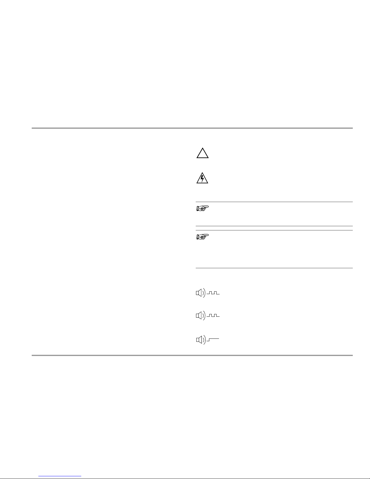
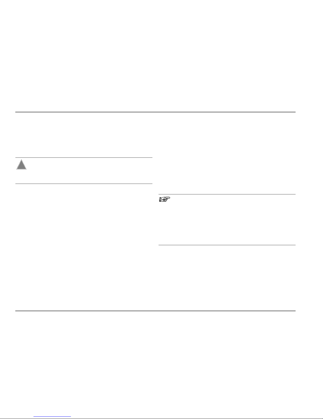
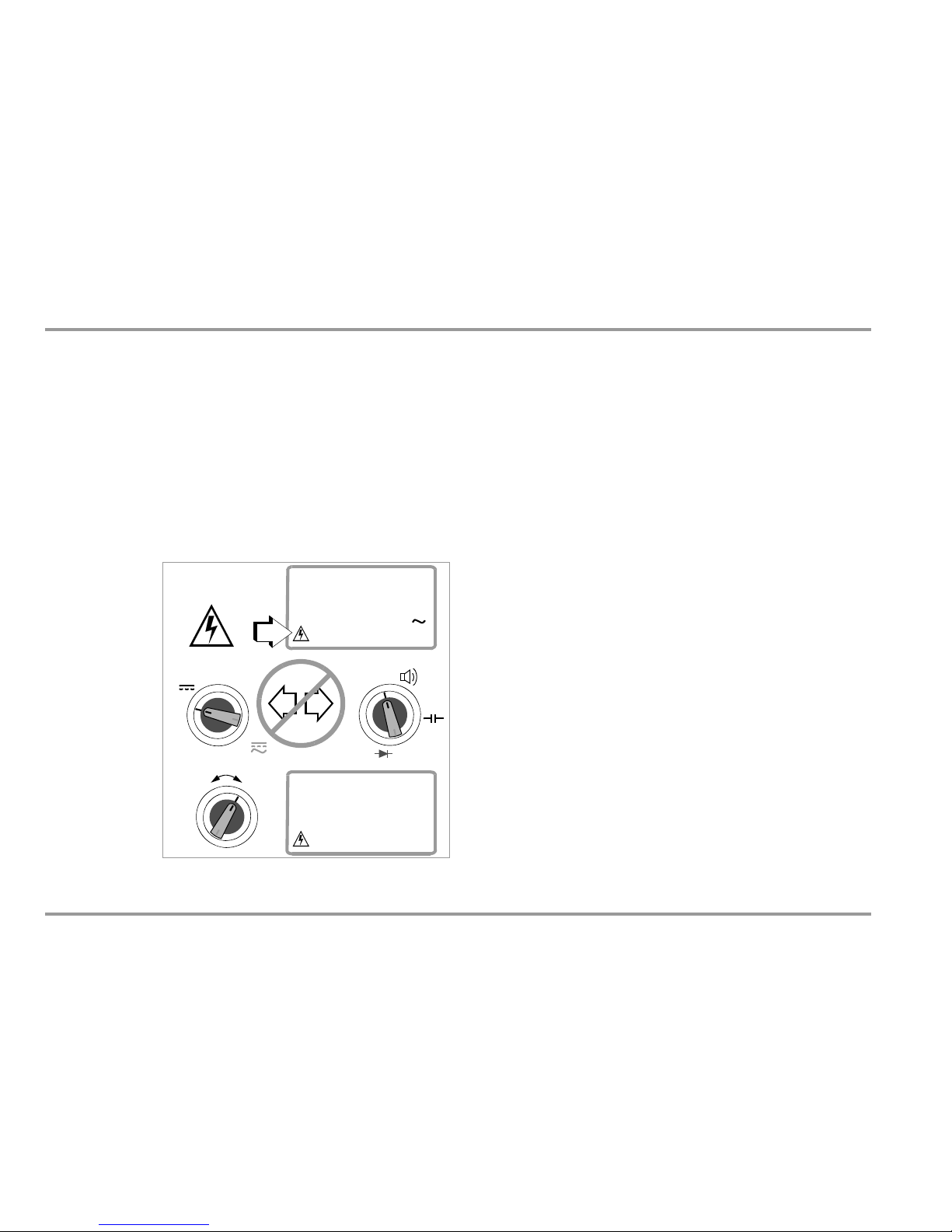
1.2 Meanings of Danger Symbols
Warning concerning a source of danger
(attention: observe documentation!)
Warning at the display regarding dangerous contact voltage
at the voltage measuring input (jacks 8 and 10, see page 10):
U > 30 V AC or U > 35 V DC
Note
For safety reasons, the instrument cannot be switched off
when dangerous contact voltages are being applied.
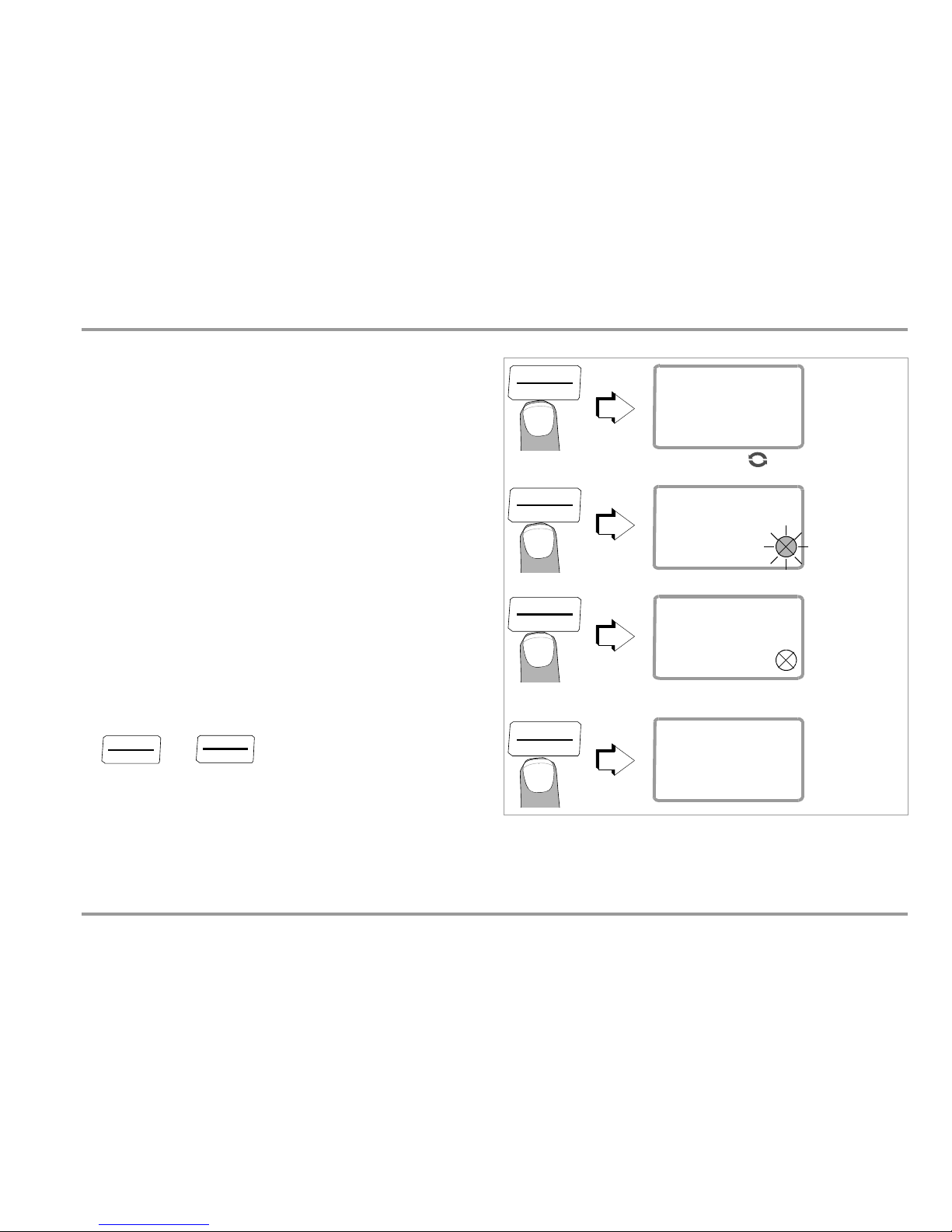
Note
Electrical discharge or high frequency interference may
cause incorrect displays to appear. To reset the instrument,
switch it off and then back on again. See also section 6.5
with regard to restoring the factory settings.
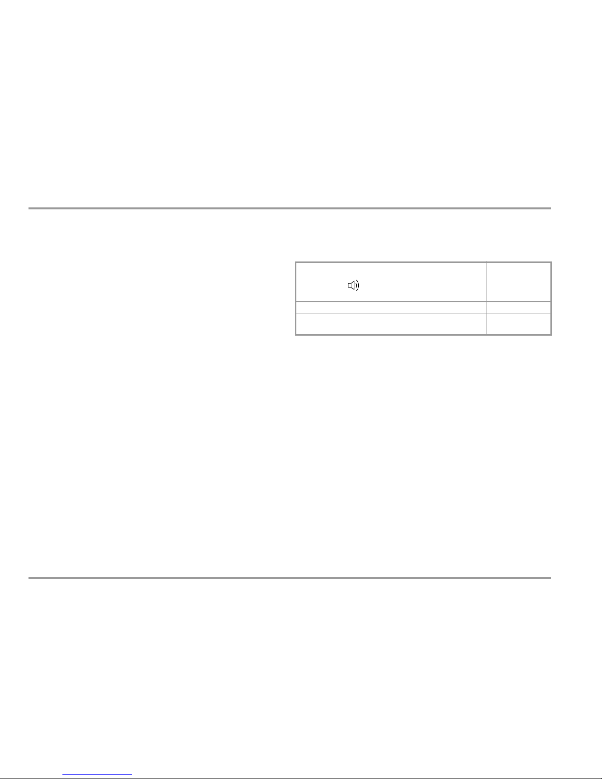
1.3 Meanings of Acoustic Warning Signals
Voltage warning: > 600 V (intermittent acoustic signal)
Current warning: > 10 A (intermittent acoustic signal)
Current warning: > 16 A (continuous acoustic signal)
!
Page 10
10 GMC-I Messtechnik GmbH
Operating Overview – Connections, Keys, Rotary Switch, Symbols
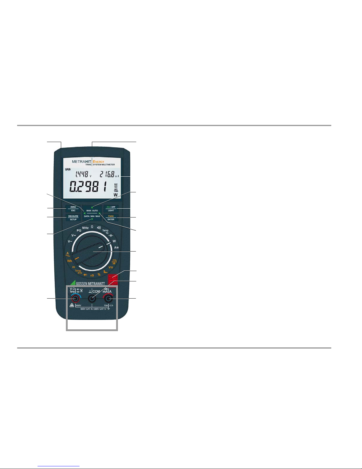
2
Operating Overview – Connections, Keys, Rotary Switch, Symbols
1 Display (LCD) (see page 12 for significance of symbols)
2 MAN/AUTO: shift key for manual/automatic measuring range selection
Increase parameter values
Operating mode menu:
selection of indiv. menu entries against direction of flow
3
ON / OFF | LIGHT
: key for switching device and display illumination on and off
4 FUNC | ENTER Multifunction key
Operating mode menu: acknowledge entry (ENTER)
5
Increase measuring range or move decimal point to the right (MAN function)
Power measurement: change displayed unit of measure
6 Rotary switch
for meas. functions
(see significance of symbols on
page 13)
7 DKD calibration mark
8 Connector socket for ground / connected to ground
9 Socket connector for direct current measurement and current clamp
transformer, with automatic blocking
10 Connector socket for voltage, resistance, temperature, diode and capacitance
measurement, and current
clamp
sensor
11 DATA/MIN/MAX: key for freezing, comparing and deleting measured value,
and for Min-Max function
Decrease values
Operating mode menu: s
election of indiv. menu entries in direction of flow
12 MEASURE | SETUP: key for switching back and forth between measuring
and menu function
13 ZERO | ESC
Key for zero balancing
Operating mode menu: Exit current menu level and
return to a higher level.
Exit parameters entry function
without saving.
14
Reduce meas. range or move decimal point to the left (MAN function)
Power measurement: change displayed unit of measure
15 Power pack connector jack
16 Infrared interface
1
3
4
16
5
6
9
*
*
sec. 4.3
sec. 3
sec. 5
sec. 7
sec. 6
sec. 3 ff.
sec. 3
13
12
sec. 4.1
10
2
sec. 4.1.2
14
8
Max. 600 V!
11
15
sec. 4.1
sec. 4.4
sec. 6
sec. 3
sec. 6
sec. 3.1
7
sec. 1.2
Page 11
GMC-I Messtechnik GmbH 11
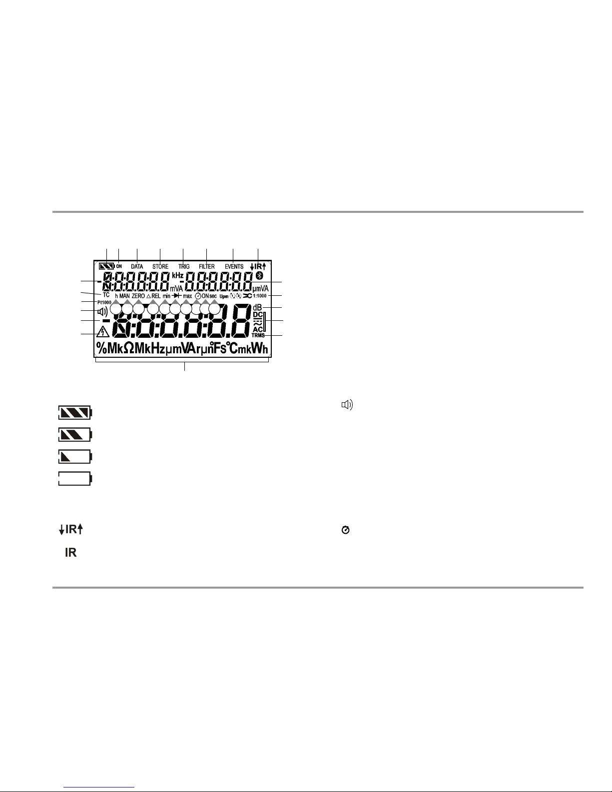
Operating Overview – Connections, Keys, Rotary Switch, Symbols
Symbols Used in the Digital Display 1 Battery level indicator
2 ON: continuous operation (automatic shutdown deactivated)
3 DATA: display memory, “freeze measured value”
4 STORE: memory mode active
5 TRIG: synchronized storage
6 FILTER: low-pass filter active
7 EVENTS: events measurement
8 IR: infrared interface indicator
9 Auxiliary display: digital display with decimal point and polarity display
10 Transformation ratio (factor for current clamp sensorc and transformers)
11 dB: alternating voltage level measurement
12 Selected type of current
13 TRMS measurement
14 Unit of measure
15 Warning regarding dangerous voltage: U > 30 V AC or U > 35 V DC
16 Main display: digital display with decimal point and polarity display
17 Continuity test with acoustic signal active
18 Pt100/Pt1000: selected platinum resistance sensor with automatic
selection of Pt100 / Pt1000
19 TC: temperature measurement with type K thermocouple (NiCr-Ni)
20 h (hours): unit of time
21 MAN: manual measuring range selection active
22 ZERO: zero balancing active
23 REL: relative measurement with reference to offset
24 min: minimum value storage
25 Diode measurement selected
26 max: maximum value storage
27 Stopwatch active or time since beginning of measurement
28 ON: together with the symbol in item 27: elapsed time since activation of the
respective function
29 sec (seconds): unit of time
Battery full
Battery OK
Battery weak
Battery (almost) dead, U < 1.8 V
Data transmission to / from multimeter, active
IR interface active (ready to receive starting
commands)
Battery Level Indicator
Interface Indicator
1 28
9
14
15
17
54 6
9
3
11
13
10
19
24 272120
18
16
25
12
7
22 23 26 2829
Page 12
12 GMC-I Messtechnik GmbH
Operating Overview – Connections, Keys, Rotary Switch, Symbols
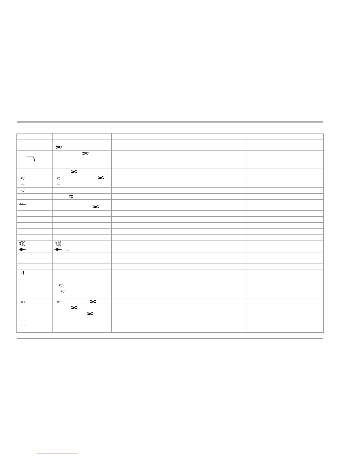
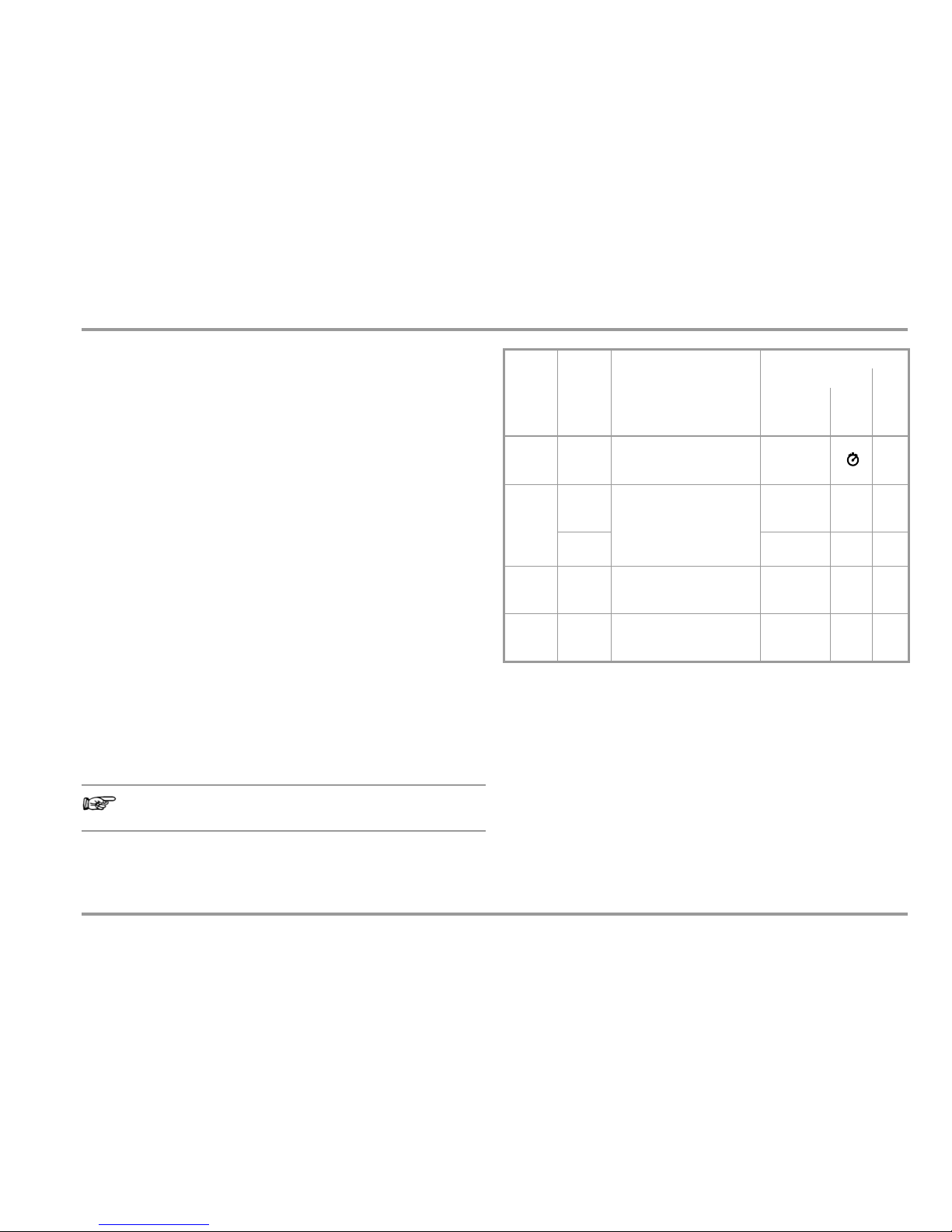
Symbols and Functions for Rotary Switch Positions (MD: main display, AD: auxiliary display, MR: measuring range)
Switch
FUNC
Display Measuring function Sub-Function
V~ 0/4 V~AC TRMS / HZ
A~AC TRMS (0/2)
CLiP=OFF: alternating voltage, AC TRMS, full bandwidth
CLiP=ON: alternating current via current clamp sensor, TRMS AC value
DATA/MIN/MAX, MAN/AUTO, ZERO
V~ 1 Hz ~AC TRMS / (1) CLiP=oFF: voltage frequency, to 300 kHz / CLiP=ON current frequency sensor DATA/MIN/MAX, MAN/AUTO, ZERO
V~ 2 V filter ~AC TRMS / Hz man Alternating voltage, AC TRMS, with low pass filter (1 kHz) DATA/MIN/MAX, MAN/AUTO, ZERO
dB 3 dB ~AC TRMS Alternating voltage level measurement DATA/MIN/MAX
V 0/4 V DC / (0/2) CLiP=OFF: direct voltage measured directly / CLiP=ON: via current clamp sensor DATA/MIN/MAX, MAN/AUTO, ZERO
V 1 V DC+ AC TRMS / CF / (1)
CLiP=OFF: pulsating voltage, direct, TRMS / CLiP=ON: via current clamp sensor
DATA/MIN/MAX, MAN/AUTO, ZERO
V 2 V DC EVENTS Direct voltage events DATA/MIN/MAX, MAN/AUTO
V 3 V~AC TRMS EVENTS Alternating voltage events DATA/MIN/MAX, MAN/AUTO
PQ 0/2 MAinS: V DC+AC TRMS Mains quality: events (type, start time, date, duration, value) Event querying: keys
1 thd % ~AC TRMS / V /
thd % ~AC TRMS / A / (0/2)
Main display: total harmonic distortion relative to fundamental frequency as %
Auxiliary display: RMS value for the total signal in V
Query harmonics 1 through 15: RMS values
and distortion via keys
MHz 0/2 MHz (High) Frequency at 5 V~ up to 1 MHz DATA/MIN/MAX, MAN/AUTO
% 1 % Duty cycle at 5 V~ DATA/MIN/MAX
0/3 (DC) resistance DATA/MIN/MAX, MAN/AUTO, ZERO
nS 1 nS Conductivity (in nano-Siemens) DATA/MIN/MAX
2RPE Low-resistance measurement with acoustic signal where Iconst = 3 mA DATA/MIN/MAX, ZERO
0/2 Continuity test, , with acoustic signal where Iconst = 1 mA DATA/MIN/MAX, ZERO
1 V DC Diode voltage up to max. 6 V where Iconst = 1 mA DATA/MIN/MAX
Temp . TC 0/2
C, type K
Temperature, type K thermocouple DATA/MIN/MAX
Temp . RT D 1°Pt100 Temperature with Pt100 / Pt1000 resistance sensor DATA/MIN/MAX, MAN/AUTO, ZERO
0/2 nF Capacitance DATA/MIN/MAX, MAN/AUTO, ZERO
m 1 km Cable length DATA/MIN/MAX, MAN/AUTO, ZERO
W 0/2 W DC+ AC TRMS / V+A / PF Power (active, reactive, apparent power) / voltage + current / power factor
DATA/MIN/MAX, MAN/AUTO
, W – VA – VAr: vw
Wh 1 Wh DC+ AC TRMS energy time Energy: energy (active, reactive, apparent energy) / on-time
Mean: average power / max: maximum power
MAN/AUTO, Wh – VAh – VArh:
vw
keys
Energy – Mean – max: , ZERO = reset
A 0/4 A DC+ AC TRMS / (2)
CLiP=OFF: pulsating current, direct, TRMS AC+DC, CLiP=ON: current clamp transformer
DATA/MIN/MAX, MAN/AUTO, ZERO
A/~ 1A DC / (3)
CLiP=OFF: direct voltage, direct, CLiP=ON: direct voltage via current clamp trans.
DATA/MIN/MAX, MAN/AUTO, ZERO
A~ 2 A~AC TRMS / Hz / (0/4) CLiP=OFF: alternating current direct, TRMS AC / current frequency,
CLiP=ON: alternating current via current clamp trans. // temperature: MB 6 A and 10 A
DATA/MIN/MAX, MAN/AUTO, ZERO
A/~ 3 thd % ~AC TRMS / A (1) Main display: total harmonic distortion relative to fundamental frequency as %
Auxiliary display: RMS value for the total signal in A
Query harmonics 1 through 15: RMS values
and distortion via keys
1kHz
Page 13
GMC-I Messtechnik GmbH 13
Operating Overview – Connections, Keys, Rotary Switch, Symbols
User Interface Symbols in the Following Sections
... Scroll through main menu
... Scroll through submenu
Select decimal point
Increase/decrease value
time Submenu/parameter (7-segment font)
1nFo Main menu (7-segment font, boldface)
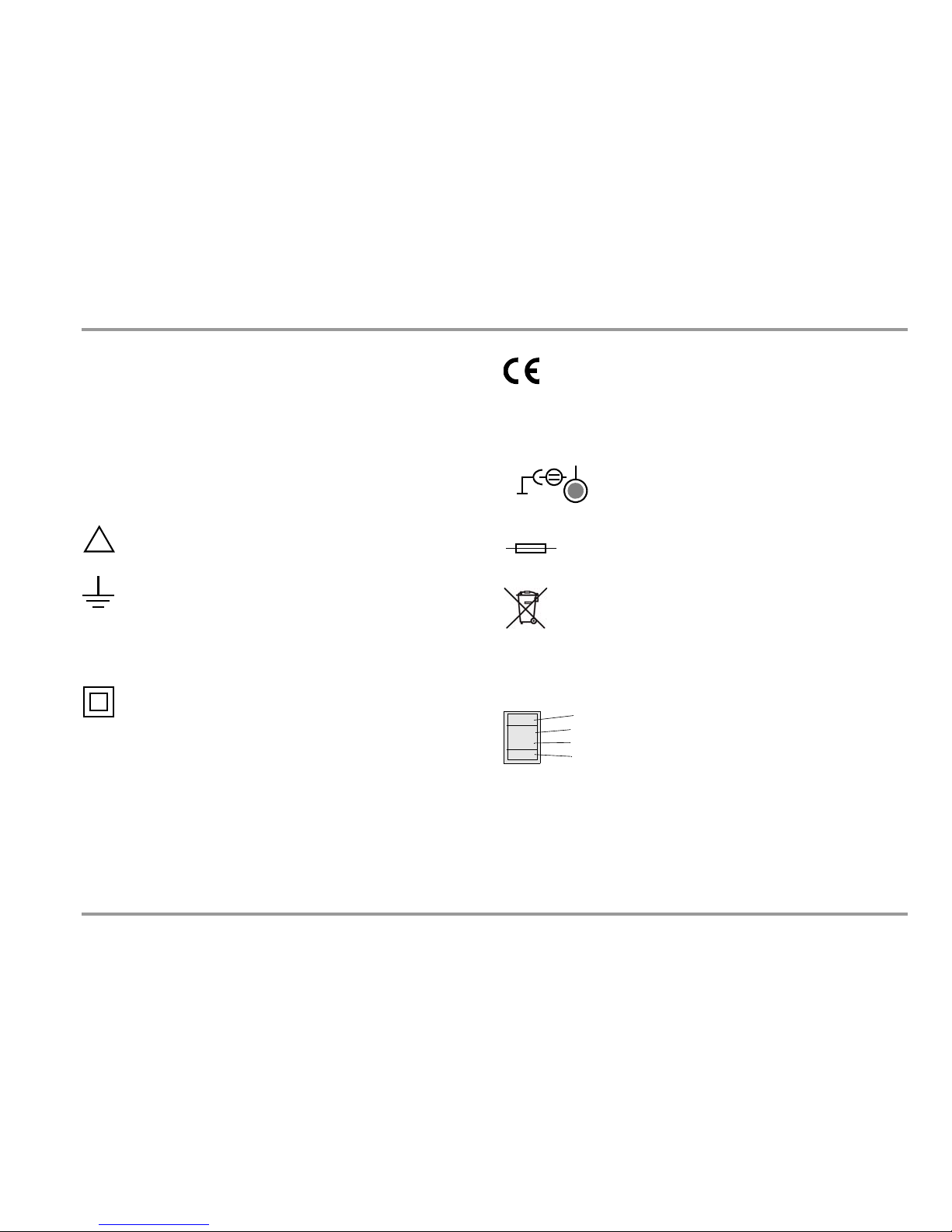
Symbols on the Device
Warning concerning a source of danger
(attention: observe documentation!)
Ground
CAT III / IV Measuring category III or IV device, see also
“Measuring Categories and their Significance per IEC
61010-1” on page 7
Continuous, doubled or reinforced insulation
EC mark of conformity
s
IR
t
Position of the infrared interface, window on the top of the
instrument
See also section 3.1 regarding location of the
power pack adapter socket.
Fuse for current measuring ranges, see section 9.3
This device may not be disposed of with the trash.
Further information regarding the WEEE mark can be
accessed on the Internet at
www.gossenmetrawatt.com under the search term
WEEE (see also section 9.5).
Calibration seal (red seal):
See also “Recalibration” on page 87.
!
5V/600mA
Consecutive number
Registration number
Date of calibration (year – month)
German Calibration Service – calibration laboratory
B0730
10-02
DKD-K-
19701
Page 14
14 GMC-I Messtechnik GmbH
Initial Start-Up – Setup
3 Initial Start-Up
3.1 Inserting Batteries or Rechargeable Batteries
Be certain to refer to section 9.2 regarding correct battery
installation.
Momentary battery voltage can be queried in the Info menu (see
section 6.3).
Attention!
!
Disconnect the instrument from the measuring circuit before opening the battery compartment lid in order to replace the batteries.
Operation With Power Pack (not included, see section 10.3)
Installed batteries are disconnected electronically if the NA X-TRA
power pack is used, and need not be removed from the instrument. If rechargeable batteries are used, they must be recharged
externally.
If the external power supply is switched off, the device is switched
to battery operation without interruption.
3.2 Switching the Instrument On
Switching the Instrument On Manually
Ð Press the ON / OFF | LIGHT key until the display appears.
Power-up is acknowledged with a brief acoustic signal. As
long as the key is held depressed, all of the segments at the
liquid crystal display (LCD) are illuminated.
The LCD is depicted on page 11.
The instrument is ready for use as soon as the key is released.
Display Illumination
After the instrument has been switched on, background illumination can be activated by briefly pressing the ON / OFF | LIGHT key.
Illumination is switched back off by once again pressing the same
key, or automatically after approximately 1 minute. If necessary,
automatic deactivation of background illumination can be disabled with the appropriate parameter setting (see bLiGht parameter
in SYStEM submenu) or via the interface.
Switching the Instrument On with a PC
The multimeter is switched on after transmission of a data block
from the PC, assuming that the “irStb” parameter has been set to
“on” (see section 6.4).
However, we recommend using the power saving mode: “off”.
Note
Electrical discharge and high frequency interference may
cause incorrect displays to appear, and may disable the
measuring sequence.
Disconnect the device from the measuring circuit. Switch the
instrument off and back on again in order to reset. If the
problem persists, briefly dislodge the battery from the connector contacts (see also section 9.2).
3.3 Setting the Operating Parameters
Setting Time and Date
See the “t iME” and “dAtE” parameter in section 6.4.
Page 15
GMC-I Messtechnik GmbH 15
Initial Start-Up – Setup
3.4 Switching the Instrument Off
Switching the Instrument Off Manually
Ð Press the ON / OFF | LIGHT key until 0FF appears at the display.
Shutdown is acknowledged with a brief acoustic signal.
If hazardous contact voltage has been detected (HV symbol
appears), the instrument cannot be switched off.
Automatic Shutdown
The instrument is switched off automatically if the measured value
remains unchanged for a long period of time (maximum measured
value fluctuation of approx. 0.8% of the measuring range per
minute or 1C or 1F per minute), and if none of the keys or the
rotary switch have been activated before a selected period of time
in minutes has elapsed (see “APoFF” parameter on page 64). Shutdown is acknowledged with a brief acoustic signal.
Automatic shutdown is disabled in the following operating modes:
continuous operation, mains analysis, power or energy measurement and whenever dangerous contact voltage has been detected (exception: memory mode).
Disabling Automatic Shutdown
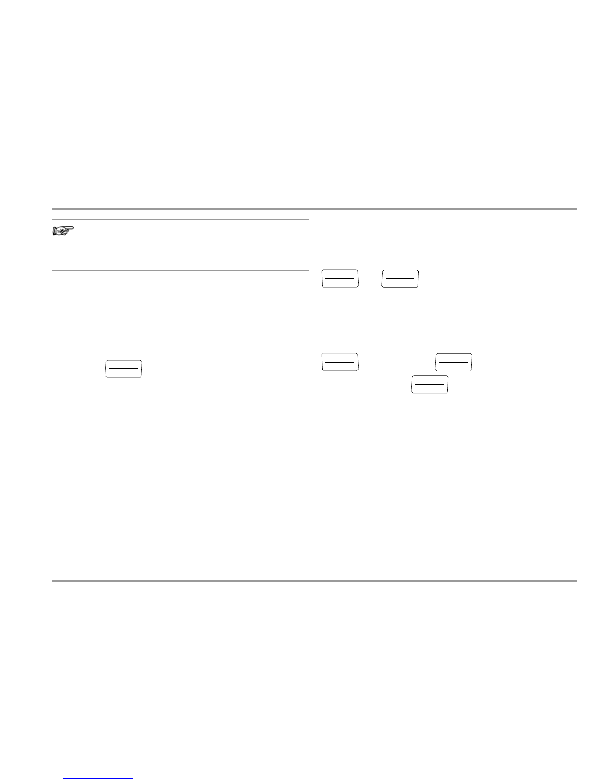
The instrument can be set to continuous operation.
Ð Simultaneously press the
and keys to this end.
The “Continuous On” function is indicated at by means of the
ON
display to the right of the battery symbol.
The “Continuous On” setting can only be canceled by changing the respective parameter (see “APoFF” on page 64 regarding instrument shutdown via parameter) or by switching the instrument off manually.
In this case, the parameter is reset to 10 minutes.
ON / OFF
LIGHT
FUNC
ENTER
ON / OFF
LIGHT
Auto-Range
8.8.8.8.8
Illumination On
000.00
ON / OFF
LIGHT
Illumination Off
000.00
ON / OFF
LIGHT
0ff
ON / OFF
LIGHT
Long
(1 s)
Page 16
16 GMC-I Messtechnik GmbH
Control Functions
4 Control Functions
4.1 Selecting Measuring Functions and Measuring Ranges
The rotary switch is linked to an automatic socket blocking mechanism which only allows access to two jacks per function (exception: the voltage jack is open during current measurement, but a
visible red ring warns the user of possible incorrect connection).
Be certain to remove the appropriate plug from its respective jack
before switching to and from the “A” functions. The socket blocking mechanism prevents the user from inadvertently turning the
selector switch to impermissible functions after the measurement
cables have been plugged in to the instrument.
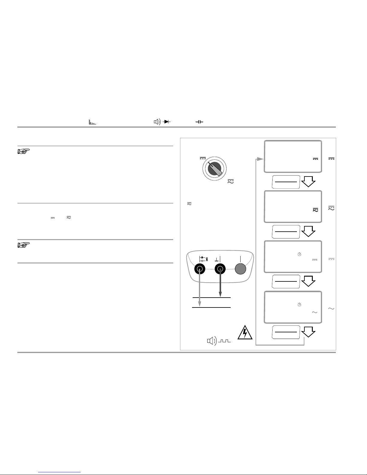
Presence of Dangerous Contact Voltages
If dangerous voltages are applied in
the high-impedance voltage measuring functions
(switch position V
or PQ), switching
to low-impedance
measuring functions (switch position MHz, , conti-
nuity, temperature
or capacitance)
causes “HiVoLt” to
appear at the display and the
respective measurement is disabled. The measuring function is not switched until dangerous contact voltage is
no longer applied to the input.
If the instrument switches itself off in the event that hazardous
contact voltage is applied (during memory mode operation with
large sampling period), the high-voltage warning symbol remains
visible at the display.
4.1.1 Automatic Measuring Range Selection (auto-ranging)
The multimeter is equipped with auto-ranging for most measuring
functions. Auto-ranging is active as soon as the instrument is
switched on. The instrument automatically selects the measuring
range which allows for highest possible resolution of the applied
quantity. When the instrument is switched to frequency measurement, the previously selected voltage measuring range remains
active.
AUTO-Range Function
The multimeter is switched automatically to the next higher range
at (61000 d + 1 d 06100 d) and to the next lower range at
(05400 d - 1 d 53999 d).
Exceptions: capacitance and cable length measurement
The multimeter is switched automatically to the next higher range
at (6100 d + 1 d 00 610 d) and to the next lower range at
(0540 d 5399 d).
4.1.2 Manual Measuring Range Selection
Auto-ranging can be deactivated and measuring ranges can be
selected manually in accordance with the following table by
pressing the
MAN / AUTO butt
on. The desired measuring range can
then be selected with the
or scroll key (exceptions: power
and energy measurement, see next page).
230.00
V
050.00
AC
TRMS
Hz
U > 35 V:
V~
V
V
PQ
MHz
%
Te mp
TC
Temp
RTD
nS
m
hivolt
Page 17

GMC-I Messtechnik GmbH 17
Control Functions
The instrument is automatically returned to automatic range
selection when the MAN / AUTO key is pressed, the rotary switch is
activated or the instrument is switched off and back on again.
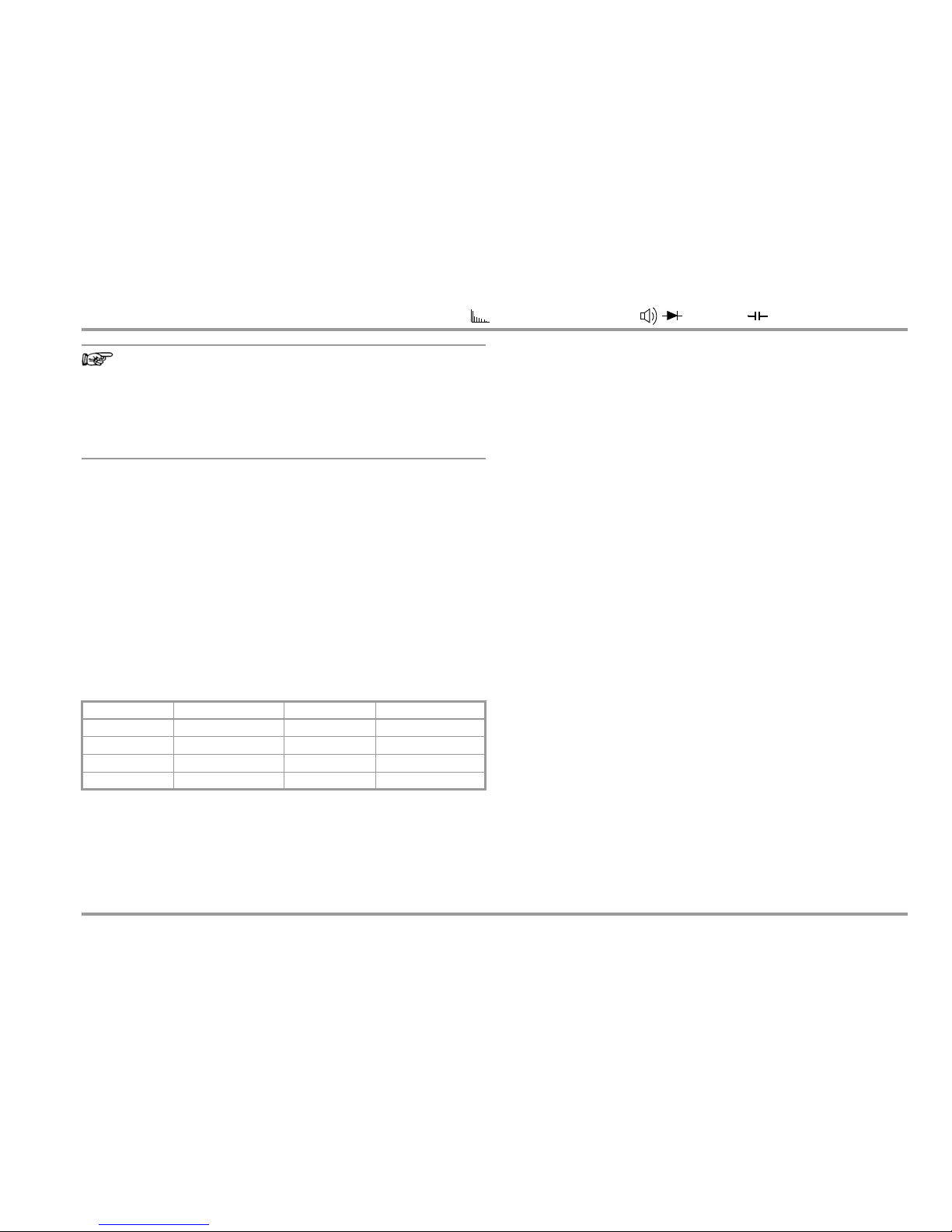
Overview: Auto-Ranging and Manual Range Selection
* Via manual measuring range selection only
“Intelligent” MAN Function
If a small measurement value occurs, the instrument can be
switched to a measuring range with higher resolution by pressing
the MAN / AUTO key.
Power and Energy Measurements
In the power meaurement function of Metrahit Energy, you can
choose between automatic measuring range selection or fixed
voltage and current measuring ranges.
In contrast to the other measuring functions, however, manual
measuring range selection is not possible in this case, as the
instrument cannot distinguish whether the voltage or current
measuring range is to be changed. The practical procedure is
therefore to start by applying the highest anticipated voltage and
current values in the case of automatic measuring range selection
and then to lock in the resulting measuring ranges by pressing the
MAN / AUTO key. Locking is disabled by pressing the key once
again.
The voltage and current measuring ranges can be selected individually when the multimeter is remote-controlled via its IR interface by using the USB X-TRA adapter (and the METRAwin10-Hit
software or control command via terminal program).
Mains and Harmonic Analysis
The measuring range for mains analysis (switch position PQ) is
specified in the menu (Set > MAinS > rAnGE).
The measuring range for harmonic analysis can be selected as a
fixed setting in the menu (Set > HArM > U.rAnGE and Set > HArM
> I.rAnGE, clamp factor is not taken into consideration!), or autoranging can be activated.
4.1.3 Peak Value Monitoring
for Automatic and Manual Measuring Range Selection
The peak value is measured in addition to RMS measurement in
the V / A DC, AC and AC+D functions, as well as for power measurement. If the peak value exceeds the valid range of the corresponding measuring path, the instrument is switched up one
range, even if the displayed measured value has not yet reached
the threshold value. If the momentary range is manually selected,
(-)OL is displayed.
This assures that, in these functions, measurement is always performed in the correct range (e.g. during measurement of a signal
with a high crest factor or measurement of the DC component of
a mixed signal with a large AC component).
Function Display
MAN / AUTO
Manual mode active:
utilized measuring range is fixed
MAN
or
Range switching sequence for:
V DC:
60 mV* 600 mV* 6 V 60 V 600 V
V AC/AC+DC:
600 mV* 6 V 60 V 600 V
Hz (V AC):
600 Hz 6 kHz 60 kHz 600 kHz
MHz
600 Hz 6 kHz 60 kHz 600 kHz 1 MHz
:
600 W 6 kW 60 kW 600 kW 6 MW 60 MW
A:
600 mA 6 mA 60 mA 600 mA 6 A 10 A (16 A)
Hz (A AC):
600 Hz 6 kHz 60 kHz 600 kHz
F:
60 nF 600 nF 6 mF 60 mF 600 mF
m:
6 km 60 km
MAN
MAN / AUTO
Return to automatic measuring range selection —
Page 18
18 GMC-I Messtechnik GmbH
Control Functions
4.1.4 Quick Measurements (MAN or DATA function)
Measurements performed using a suitable fixed measuring range
are executed more quickly than those which utilize automatic
range selection. Quick measurement is made possible with the
following two functions:
• Manual measuring range selection, i.e. selection of the measuring
range with the best resolution (see section 4.1.2)
or
•With the DATA function (see section 4.4) In this way, the appro-
priate measuring range is selected automatically after the first
measurement and the second measurement is executed more
quickly.
The selected measuring range remains active for the subsequent
series of measurements with these two functions.
4.2 Zero Offset / Relative Measurements – ZERO/Delta REL Function
Zero offset or a reference value for relative measurements can be
stored to memory depending upon deviation from the zero point:
The relevant reference or correction value is deducted individually
for the respective measuring function as an offset from all future
measurements and remains in memory until deleted, or until the
multimeter is switched off.
Zero balancing and reference value adjustment can be used for
auto-ranging, as well as for manual measuring range selection.
Zero Balancing
Ð Plug the measurement cables into the instrument and connect
the free ends to each other, except for capacitance
measurement in which case the ends of the cables are not
connected to each other.
Ð Briefly press the ZERO | ESC key.
The instrument acknowledges zero balancing with an acoustic
signal, and the “ZERO REL” symbol appears at the LCD. The
value measured at the moment the key is pressed serves as a
reference value.
Ð Zero balancing can be cleared by once again pressing the
ZERO | ESC key.
Deviation from Zero Point
– with short-circuited measurement cables
for V, , R
PE
, , A
– with open input for capacitance unit of measure (F)
Display
(0 ... 200) digits ZERO REL
(200 ... 25000) digits
(10 A measuring range: up to 5000 digits)
REL
Page 19

GMC-I Messtechnik GmbH 19
Control Functions
Setting the Reference Value
Ð Plug the measurement cables into the instrument and measure
a reference value (max. 25,000 digits, or 5000 digits in 10 A
range)
Ð Briefly press the ZERO | ESC key.
The instrument acknowledges storage of the reference value
with an acoustic signal, and the “ZERO REL” or the “REL”
symbol appears at the LCD. The value measured at the moment the key is pressed serves as a reference value.
Ð The reference value can be cleared by once again pressing the
ZERO | ESC key.
Notes Regarding Relative Measurement
• Relative measurement effects the main display only.
• In the case of relative measurement, , F or AC quantities may
also appear as negative values.
4.3 Display (LCD)
Measured Value, Unit of Measure, Type of Current, Polarity
The measured value with decimal and plus or minus sign appears
at the digital display. The selected unit of measure and current
type are displayed as well. A minus sign appears to the left of the
value during the measurement of zero-frequency quantities, if the
plus pole of the measured quantity is applied to the “” input.
Overranging
“0L” (overload) is displayed as of 61,000 digits.
Exceptions: “OL” appears at the display as of 6100 digits for measuring functions with a measuring range span of 6000 digits.
Page 20
20 GMC-I Messtechnik GmbH
Control Functions
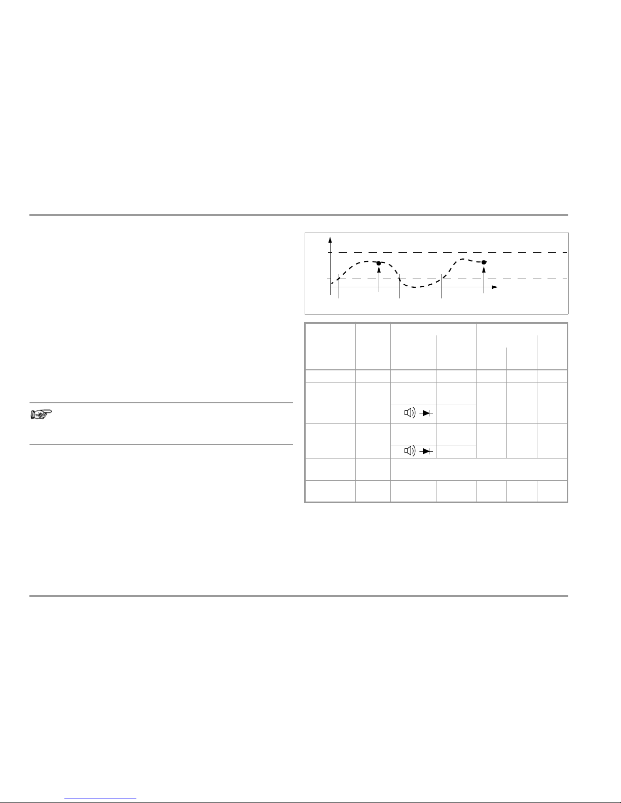
4.4 Measured Value Storage: DATA (auto-hold / compare)
An individual measured value can be automatically “frozen” with
the DATA function (auto-hold). This is useful, for example, when
contacting the measuring points with the test probes requires
your full attention. After the measuring signal has been applied
and the measured value has settled in in accordance with the
“condition” listed in the table below, the measured value is frozen
at the digital display and an acoustic signal is generated. The test
probes can now be removed from the measuring points, and the
measured value can be read from the digital display. If the measuring signal falls below the value specified in the table, the function is reactivated for storage of the next value.
Measured Value Comparison (DATA compare)
If the currently frozen value deviates from the first saved value by less
than 100 digits, the acoustic signal is generated twice. If deviation is
greater than 100 digits, only a brief acoustic signal is generated.
Note
The selected measuring range cannot be manually changed
as long as the DATA function is active.
The DATA function is deactivated by pressing and holding the
DATA/MIN/MAX key (approx. 1 second), when the measuring function is changed, or when the instrument is switched off and back
on again.
DATA Function in Memory Mode Operation (rAtE parameter = dAtA)
If dAtA is selected as the storage rate under the StorE > rAtE measuring parameter setting, and if memory mode operation is then
started, measured values “frozen” with activated DATA function are
automatically saved to permanent memory with time stamp.
1
Reactivation results from falling short of specified measured value limits.
2
Two acoustic signals are generated the first time a measured value is saved as a
reference value. For subsequent data hold, two acoustic
signals are only generated if the currently frozen value deviates from the first saved
value by less than 100 digits.
Key: MV = measured value, MR = measuring range
Function
DATA
Data/
Min/Max
Key
Condition Response from Instrument
Measuring
Function
Measuring
Signal
Display
Acous-
tic
Digital
MV
DATA
Activate Brief Blinks Once
Save
(stabilized
measured
value)
V, A, Hz, dB,
F, M H z, %
> 10%
rdg.
Is
dis-
played
Static
Once
Twi ce
2
0L
Reactivate
1)
V, A, Hz, dB,
F, M H z, %
< 10%
rdg.
Stored
MV
Blinks
= 0L
Change to
Min/Max
Brief See table in section 4.4.1
Exit Long
Is
deletedIsdeleted
Twi ce
V, A , Hz
t [s]
60,000
6000
Activated
Reactivated
Save
Save
dB, F, MHz, %
Digits
Digits
100% of measuring range
10% of measuring range
Page 21
GMC-I Messtechnik GmbH 21
Control Functions
Example
The voltage measuring range is set manually to 6 V. The first measured value is 3 V and is stored to memory because it is greater
than 10% of the measuring range (6000 digits = 0.6 V), and is
thus reliably above the background noise level. As soon as the
measured value drops to less than 10% of the measuring range
(6000 digits), i.e. amounts to less than 6 V which corresponds to
removal of the test probes from the measuring point, the instrument is ready to store a new value.
4.4.1 Saving Minimum and Maximum Values – Min/Max Function
Minimum and maximum measured values applied to the measuring instrument’s input after the Min-Max function has been activated can be “frozen” at the auxiliary display along with time of
occurrence. The most important use of this function is the determination of minimum and maximum values during long-term measured value observation.
Except during power measurement, the Min-Max function has no
effect on the main display, at which the current measured value
continues to appear.
Apply the measured quantity to the instrument and set the measuring range with the MAN / AUTO key before activating the Min-
Max function.
The Min-Max function is deactivated by pressing and holding the
DATA/MIN/MAX key (approx. 1 second), when the measuring function is changed, or when the instrument is switched off and back
on again.
Note
Extreme values can be reset by pressing the ZERO key.
Power Measurement (special case)
Instantaneous power is displayed with the switch in the W setting.
The Min-Max function is activated with the DATA/MIN/MAX key. The
minimum and maximum values for active, reactive and apparent
power are displayed as of the beginning of the power measurement, along with time of occurrence (date and time).
Previous Min-Max values can be cleared without exiting the function by pressing the ZERO key.
This function differs from the general Min-Max function insofar as
measurement is performed continuously in the background, even
if the Min-Max display is not shown, and while the instrument is in
the energy measuring mode
Min-Max
Function
Data/
Min/Max
Key
Min. and Max.
Measured Values
Response from Instrument
Display
Acous
tic
Sig-
nal
Digital
Measured
Valu e
Max.
Min.
1
Activate
and save
DATA/
MIN/MAX
1 x brief
Are
saved
Current
measured
value
Once
2
Save and
display
DATA/
MIN/MAX
Brief
Storage continues in the back-
ground, new min. and max.
values are displayed together
with time.
Saved min.
value
Min. Once
Brief
Saved max.
value
Max. Once
Reset
ZERO/
ESC
Brief
Are deleted
Saved min.max. values
min/
max
1
Stop
DATA/
MIN/MAX
Long
are deleted
and function is exited
Current
measured
value
Is dele-
ted
Twi ce
Page 22
22 GMC-I Messtechnik GmbH
Control Functions
4.5 Measurement Data Recording – Memory Mode Operation, STORE
Menu Function
The system multimeter is capable of recording measurement data
using an adjustable sampling rate for long periods of time in the
form of measurement series. Data are stored to permanent memory, an68: EnErGY Submenud are retained even after the multimeter is switched off, as well as after battery replacement.
Stored measured values can subsequently be read out at the
computer. The only prerequisite is a PC which is connected by
means of an interface cable to the USB X-TRA bidirectional interface adapter, which is plugged onto a system multimeter. See
also section 7, “Interface Operation”.
Memory Parameters Overview
Preparing for Recording – Parameter Settings
Ð First set the sampling rate for memory mode operation (see
section 6.4 the rAtE parameter).
Ð Set hysteresis for efficient use of available memory space.
During memory mode operation, new measured data are only
saved if they deviate from the previously stored value by an
amount which exceeds the selected hysteresis value (see
section 6.4, “hyst” parameter).
Ð Set “t.StorE” in order to limit recording duration.
Ð First select the desired measuring function and an appropriate
measuring range.
Ð Check the battery charge level before starting long-term mea-
surement recordings (see section 6.3).
Connect the NA X-TRA power pack if applicable.
Starting Recording via Menu Functions
Ð Switch to the “SET” mode by pressing MEASURE | SETUP and
select the “StorE” menu.
1nFo
... StorE store off StArt (blinks)
store
Ð Memory mode operation is started by acknowledging the
blinking “start” prompt at the main display with the FUNC |
ENTER key. The
STORE display segment appears in the header
and indicates that the memory mode has been activated.
“store” appears at the main display.
Ð Press the MEASURE | SETUP key in order to return to the measur-
ing function.
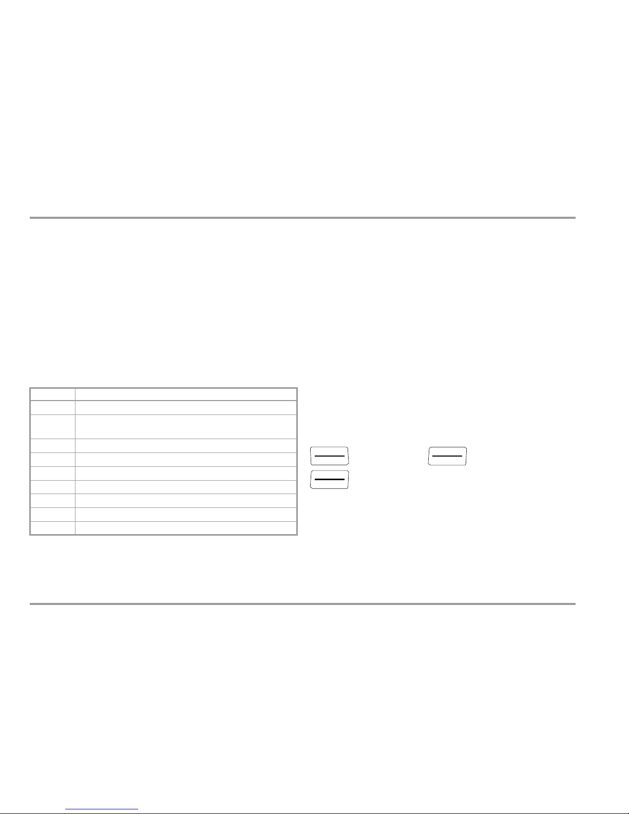
Parameter Page: Header
CLEAr
23: Clear Memory
dEMAnd
tiME
66: tEMP unit – Select a Unit of Measure for Temperature
EMpty
23: Clear Memory – appears after CLEAr
hyst
73: HYSt – Hysteresis (parameter for memory mode operation)
0CCvP
23: Querying Memory Occupancy
rAtE
68: EnErGY Submenu
StArt
22: Starting Recording via Menu Functions
StoP
23: Ending Recording
t.store
74: tStorE – Recording Time (parameter for memory mode operation)
MEASURE
SETUP
FUNC
ENTER
FUNC
ENTER
Page 23
GMC-I Messtechnik GmbH 23
Control Functions
Note
The StorE > StArt and StorE > CLEAr menu functions can
only be selected a long as memory is not completely full
(StorE > StArt), or not completely empty (StorE > CLEAr).
Ending Recording
Ð If the instrument is in the measuring mode, return to the menu
function by pressing the MEASURE | SETUP key. Select “StorE”
again and acknowledge by pressing the FUNC | ENTER key.
“StoP” blinks at the main display.
store on StoP store
Ð Acknowledge the “StoP” display by pressing FUNC | ENTER.
The
STORE display segment in the header is cleared, indicating
that recording has been ended.
Ð Press the MEASURE | SETUP key in order to return to the measur-
ing function.
Ð Memory mode operation can also be exited by switching the
multimeter off.
Querying Memory Occupancy
Memory occupancy can be queried during recording with the
help of the “1nFo” menu (see also section 6.3).
Memory occupancy range: 000.1% to 099.9%.
1nFo
bAtt
x.x V
...
0CCvP :
017.4
%
Clear Memory
This function deletes all measured values from memory! (blinks)
It’s advisable to execute this function before starting a new
measurement data recording.
1nFo
... StorE store off StArt (blinks)
store CLEAr no yes empty store
Storage of Individual Values Using the SAMPLE or dAtA Sampling Rate
If only individually selected values need to be saved, the SAMPLE
value must be selected as the StorE > rAtE sampling value. If
memory mode operation is then started, a single measured value
is saved to permanent memory with time stamp when the DATA/
MIN/MAX key is pressed and held until two rapidly repeating
acoustic signals are generated (not in the case of mains analysis).
If dAtA is selected as the StorE > rAtE sampling rate, and if memory mode operation is then started, measured values ascertained
with activated DATA function are automatically saved to permanent memory with time stamp.
FUNC
ENTER
MEASURE
SETUP
FUNC
ENTER
MEASURE
SETUP
FUNC
ENTER
FUNC
ENTER
Page 24

24 GMC-I Messtechnik GmbH
Control Functions
4.5.1 Rapid Momentary Value Acquisition for U DC and I DC
Rapid momentary value acquisition is only activated during memory mode operation in the U DC and I DC functions, and only after
selecting a sampling period of 0.5, 1, 2, 5, 10, 20 or 50 ms: All
trigger and hysteresis functions are available, although the
momentary value is acquired with a separate measuring circuit.
This allows for the recording of the waveshapes of low-frequency
signals with reduced resolution and accuracy (typically < 1% of the
measuring range under reference conditions, not specified).
Roughly 300,000 measured values can be saved in this mode.
Values of up to about 1.9 x Umax or Imax are recorded (with fixed
range, range-dependent fluctuations), and thus the range limit
can be exceeded by approximately 90%.
Note
The ZERO/REL function is not taken into consideration for
rapid momentary value acquisition!
4.5.2 Power and Energy Measurement in the Memory Mode
The value selected for the SEt > EnErGY > StorE menu parameter
specifies which values from power and energy measurements will
be saved during memory mode operation:
• SEt > EnErGY > StorE = normal (default setting):
Momentary values for current, voltage, active, reactive and
apparent power, as well as power factor, are acquired and
saved to memory at the selected sampling rate (at least 0.5 s).
• SEt > EnErGY > StorE = demand:
The instrument only saves mean power values at the end of the
dEMAnd tiME observation period
(see section 6.4.4, “dEMAnd tiME” parameter).
• SEt > EnErGY > StorE = all:
Momentary values are saved at the selected sampling rate and
mean power values are saved at the end of each dEMAnd
tiME observation period
(see section 6.4.4, “dEMAnd tiME” parameter).
Ð Set the dEMAnd tiME interval for memory mode operation
before you start recording.
Page 25
GMC-I Messtechnik GmbH 25
Measurements: V/Hz/dB – PQ/ – MHz/% – /nS/RSL
– / –
Temp – /m – W/Wh – A/Hz/thd
5 Measurements
5.1 Voltage Measurement
Notes Regarding Voltage Measurement
• The multimeter may only be operated with installed batteries or rechargeable batteries. Dangerous voltages are otherwise not indicated,
and the instrument may be damaged.
• The multimeter may only be operated by persons who are capable of recognizing contact hazards and taking the appropriate
safety precautions. Contact hazards exist anywhere, where voltages of greater than 33 V (RMS) may occur.
The test probes may only be only gripped up to the finger guard.
Do not touch the metallic test probes under any circumstances.
• Avoid working alone when taking measurements which involve
contact hazards. Be certain that a second person is present.
• Maximum permissible voltage between the connector sockets, (9
and 10) and ground (8) is 600 V for measuring category III and
300 V for measuring category IV. An acoustic signal is generated
at a display value of greater than 600.0 V in the 600 V range (intermittent acoustic signal: 250 ms on, 250 ms off).
• Power limiting: < 6 x 10
6
Volts x Hertz.
• Be prepared for the occurrence of unexpected voltages at devices
under test (e.g. defective devices). For example, capacitors may
be dangerously charged.
• No measurements may be made with this instrument in electrical circuits with corona discharge (high-voltage).
• Special care is required when measurements are made in HF
electrical circuits. Dangerous pulsating voltages may be present.
• Be aware of the fact that dangerous voltage spikes are not displayed
during measurement with the low-pass filter.
We recommend measuring voltage without the low-pass filter first, in
order to be able to detect any dangerous voltages.
• Be absolutely certain that the measuring ranges are not overloaded beyond their allowable capacities. Limit values are included in section 8, "Technical Data”, in the table entitled
“Measuring Functions and Measuring Ranges” in the “Overload
Capacity” column.
• With the rotary switch in the V position, the instrument is
always in the 6 V measuring range immediately after it’s
switched on. As soon a the MAN / AUTO key is pressed, and assuming the measured value is less than 600 mV, the instrument
is switched to the mV measuring range.
Scope of Functions, Voltage Measurement
1
A 1 kHz low-pass filter can be used in this case, in order to filter out high frequency
pulses of greater than 1 kHz, for example when performing measurements at
pulsed motor drives.
Function
V AC / Hz TRMS, dB
(Ri 9 M)
1
V AC / TP-Filter 1 kHz
1
(Ri 9 M) TRMS
V AC+DC TRMS
(Ri 9 M)
V DC (Ri 17 M)
MHz at 5 V AC
Duty cycle as %
Frequency bandwidth
100 kHz
Page 26
26 GMC-I Messtechnik GmbH
Measurements: V/Hz/dB – PQ/ – MHz/% – /nS/RSL
– / –
Temp – /m – W/Wh – A/Hz/thd
5.1.1 Direct Voltage, Pulsating Voltage and Crest Factor Measurement
– V DC, V (DC+AC) and CF
Note
Set the CL iP parameter to 0FF in the current clamp setup
menu. Otherwise all measured values are displayed in
amperes, corrected by the amount resulting from the
selected transformation ratio for an interconnected current
clamp sensor. The clamp symbol is also displayed. Refer to
section 6.4, "Entering Parameters – SETUP Menu”
,
regarding adjustment.
Ð In accordance with the voltage to be measured, turn the rotary
switch to V or V .
Ð Connect the measurement cables as shown.
The “” connector jack should be grounded.
Note
An intermittent acoustic signal warns the operator if the measured value exceeds the upper range limit in the 600 V range.
Make sure that a current measuring range (“A”) has not been activated when the multimeter is connected for voltage measurement!
If the fuse’s blowing limits are exceeded as a result of operator
error, both the operator and the instrument are in danger!
With the rotary switch in the V position (auto-ranging), the multimeter is always in the 6 V measuring range immediately after it’s switched on. As soon a the MAN / AUTO key is pressed, and assuming
the measured value is less than 600 mV, the instrument is switched to the 600 mV measuring range. Press the
key in order to
switch to the 60 mV measuring range.
COM
V
Tem p
– (+)
+ (–)
V= : 60 mV 600 V
20,000
V
DC
AC
TRMS
20,000
V
DC
V
V
V
V
> 30 V AC or > 35 V DC:
> 600 V:
Warnings regarding dangerous
max. 600 V (< 10 kHz)
V: 600 mV 600 V
max. 100 V (> 10 kHz)
P
max
= 6 x 10⁶ V x Hz
Measuring ranges:
000000
20.000 00:00:00
V
Cf: 01.0
EVENTS
MAN
DC
000000
00.000 00:00:00
V
EVENTS
MAN
AC
TRMS
voltage:
V
V
FUNC
ENTER
FUNC
ENTER
FUNC
ENTER
FUNC
ENTER
CL ip = 0FF
!
CF: 1.0 ... 11.0
Page 27
GMC-I Messtechnik GmbH 27
Measurements: V/Hz/dB – PQ/ – MHz/% – /nS/RSL
– / –
Temp – /m – W/Wh – A/Hz/thd
Note
60 mV range:
Thermovoltages occur in the event of temperature fluctuation, which appear as additional voltage offset. It may be
necessary to repeat zero offsetting in order to achieve the
specified degree of accuracy.
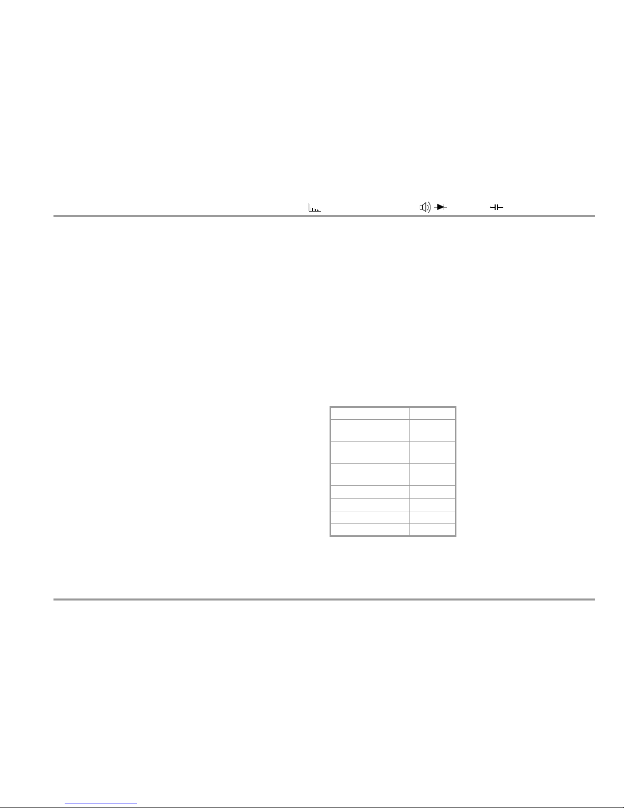
Crest Factor Display
Crest factor is displayed for voltages in the V (AC+DC) function
along with the measured voltage value. The voltage value is measured simultaneously in a separate measuring circuit to this end,
and crest factor is displayed within a range of 1.0 to 11.0.
This value indicates the quality of the applied signal. The only prerequisite is a periodic signal with a valid frequency (see table).
Measuring range: 1.0
CF 11.0; resolution: 0.1
Typical (not specified) maximum deviation
for U 5% of the measuring range:
Frequency CF 3.0 3.0 < CF 5.0 5.0 < CF 10.0
10 to 70 Hz 02 02 05
70 to 440 Hz 02 05 Not valid
440 Hz to 1 kHz 05 Not valid Not valid
> 1 kHz: Not valid Not valid Not valid
Page 28
28 GMC-I Messtechnik GmbH
Measurements: V/Hz/dB – PQ/ – MHz/% – /nS/RSL
– / –
Temp – /m – W/Wh – A/Hz/thd
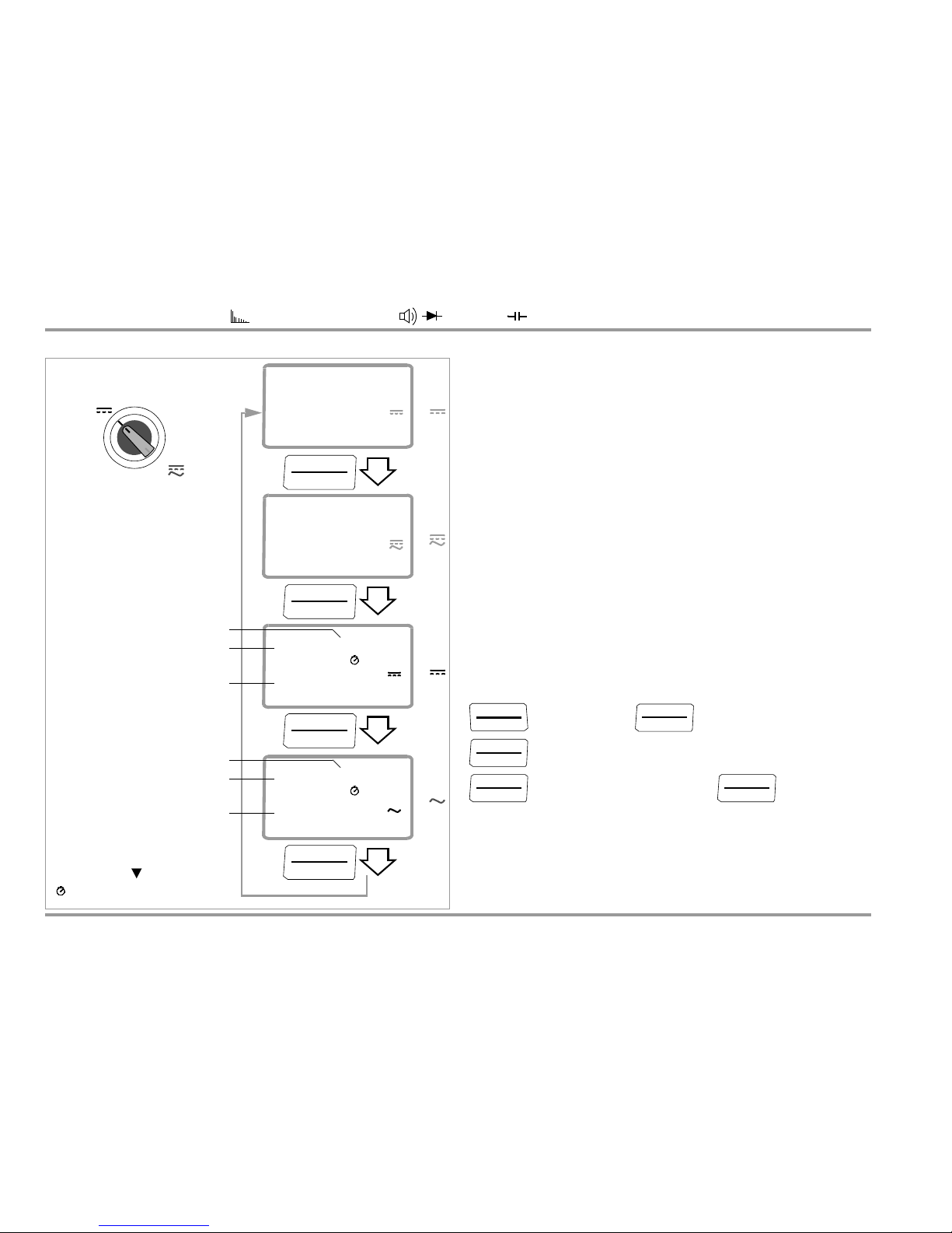
Events Recording “EVEntS” Events recording can be activated with DC or AC coupling in the
V DC switch position. The auto-ranging function is deactivated,
and the respective valid measuring range must be selected manually in the left-hand auxiliary display.
The following can be measured and displayed:
• Number of events
An event is recorded whenever at least 1 measured value has
fallen short of the L-trig threshold and subsequently at least 1
measured value has exceeded the H-trig threshold.
Voltage signals with a repetition frequency of less than 500 Hz
or 2 Hz are recorded (event rate or period of 0.001 s or 0.5 s).
• Total time for all events
Time during which measured voltage was above the upper
trigger threshold.
• Total time elapsed since event recording was started
Event Recording Parameter with DC Coupling – DC Sampling Rate
Ð Enter the desired sampling rate in the parameter settings
menu:
1nFo ... SET system ... events
events trig / events rate DC
events rate : 0 ..001 /0..5 s
20.000
V
DC
AC
TRMS
20.000
V
DC
V
V
V
V
000.000
20,000 00:00:00
V
Cf: 01.0
EVENTS
MAN
DC
000.000
00,000 00:00:00
V
EVENTS
MAN
AC
TRMS
V
V
FUNC
ENTER
FUNC
ENTER
FUNC
ENTER
FUNC
ENTER
CL ip = 0FF
!
Number of elements
Time elapsed since recording start
Event value
DC coupling
Number of elements
Time elapsed since recording start
Event value
AC coupling
(sampling rate: 0.5 s / 1 ms)
(sampling rate: 0.5 s)
Total time for all eventsOn
DATA/MIN/MAX
MEASURE
SETUP
FUNC
ENTER
FUNC
ENTER
FUNC
ENTER
FUNC
ENTER
Page 29
GMC-I Messtechnik GmbH 29
Measurements: V/Hz/dB – PQ/ – MHz/% – /nS/RSL
– / –
Temp – /m – W/Wh – A/Hz/thd
Note
1 ms sampling is executed with reduced resolution and
accuracy (approx. 1% of the measuring range under reference conditions).
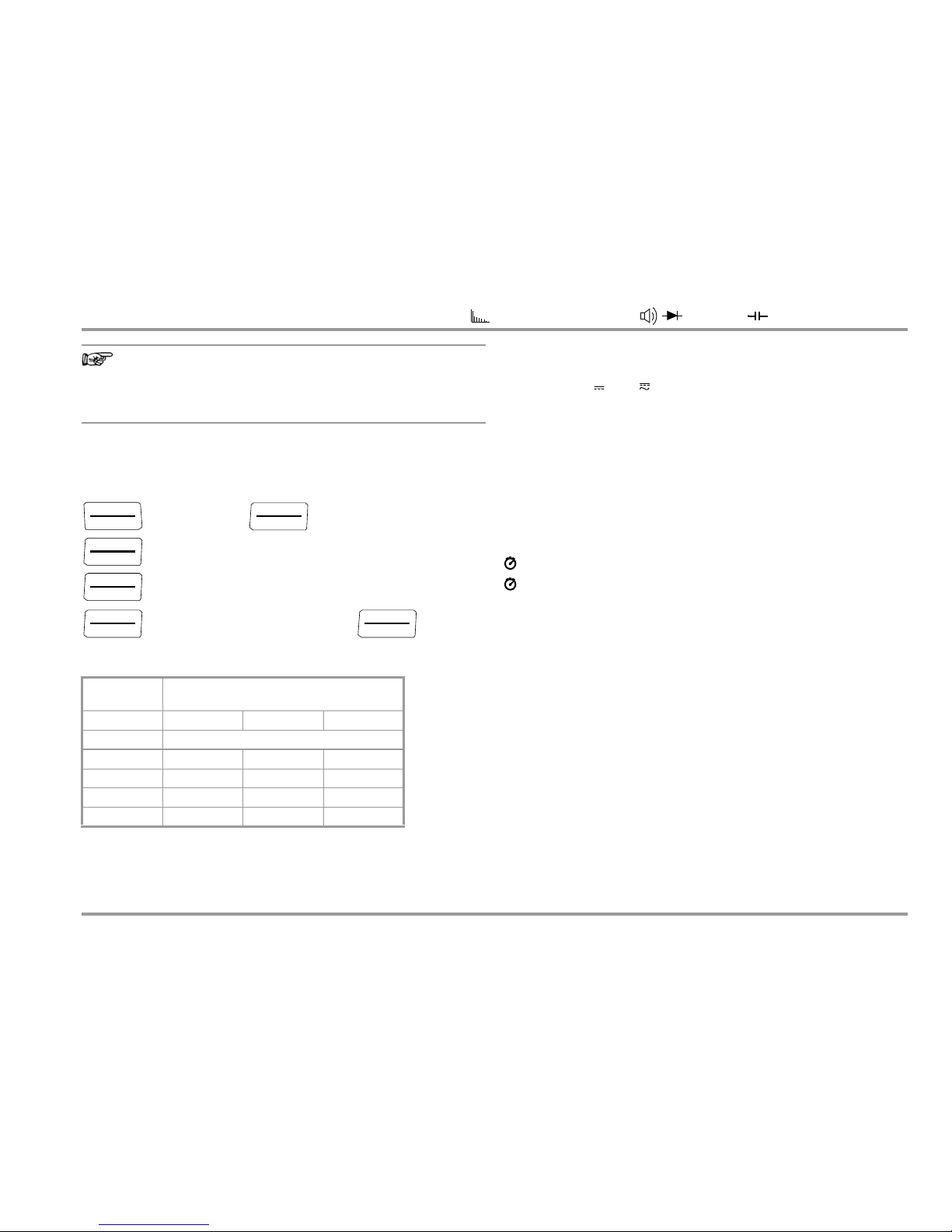
Events Measurement Parameter – Trigger Thresholds
Ð Enter upper threshold H-trig and lower threshold L-trig in digits in
the parameter settings menu (see table with examples below):
1nFo
... SET system ... events
events rate DC / events trig
h-trig set : -60000 ... +60000
l-trig set : -60000 ... +60000
Examples of Trigger Threshold Entries
Selecting the Measurement
Ð In accordance with the voltage to be measured, turn the rotary
switch to V or V .
Ð Manually select the measuring range for the event value in the
left-hand auxiliary display.
Ð Apply the signal as you would for a voltage measurement.
Ð Repeatedly press the multifunction key (FUNC | ENTER) until
EVENTS (DC) or EVENTS (AC) appears at the display.
You can switch back and forth between two times with the DATA/
MIN/MAX key:
Total time elapsed since event recording was started
ON Total time of all events (voltage above H-triG)
Entered Value:
H-trig or L-trig Trigger Threshold in Digits
20 000 02 000 00 200
Meas. range Effective trigger threshold
600 mV 200 mV 20 mV 2 mV
6 V 2 V 200 mV 20 mV
60 V 20 V 2 V 200 mV
600 V 200 V 20 V 2 V
MEASURE
SETUP
FUNC
ENTER
FUNC
ENTER
FUNC
ENTER
FUNC
ENTER
FUNC
ENTER
Page 30
30 GMC-I Messtechnik GmbH
Measurements: V/Hz/dB – PQ/ – MHz/% – /nS/RSL
– / –
Temp – /m – W/Wh – A/Hz/thd
5.1.2 Alternating Voltage and Frequency Measurement V AC and Hz
with Selectable Low-Pass Filter, V AC + FILTER and dB V AC
Note
Set the CL iP parameter to 0FF in the current clamp setup
menu.
Otherwise all measured values are displayed in amperes,
corrected by the amount resulting from the selected transformation ratio for an interconnected current clamp sensor.
The clamp symbol is also displayed. Refer to
section
6.4, "Entering Parameters – SETUP Menu”
,
regarding adjustment.
Ð In accordance with the voltage or frequency to be measured,
turn the rotary switch to V~.
Ð Connect the measurement cables as shown.
The “” connector jack should be grounded.
Voltage measurement
Note
An intermittent acoustic signal warns the operator if the measured value exceeds the upper range limit in the 600 V range.
Make sure that a current measuring range (“A”) has not been activated, when the multimeter is connected for voltage measurement!
If the fuse’s blowing limits are exceeded as a result of operator
error, both the operator and the instrument are in danger!
Ð You can switch back and forth between voltage measurement
with and without low-pass filter.
Ð Repeatedly press the multifunction key (FUNC | ENTER) until the
unit of measure V, or V and FILTER, appears at the display.
Frequency Measurement
Signal frequency appears at the left-hand auxiliary display when
the instrument executes alternating voltage measurements. A
separate frequency measurement can be additionally performed
by pressing the FUNC | ENTER key, which allows for use of the DATA
and Min-Max functions.
If the measuring signal is too low, switch manually to a lower
range.
Lowest measurable frequencies and maximum allowable voltages
are listed in section 8, "Technical Data”.
Note
For measurements close to the trigger threshold: display
error or zero. Select a lower voltage measuring range. In the
case of measured values which are many times greater than
the expected results, the input signal may be distorted. If this
is the case, perform a measurement with activated 1 kHz
low-pass filter.
Measurement with Low-Pass Filter
Attention!
!
Be aware of the fact that dangerous voltage spikes are not
displayed during this type of measurement (see also
“Voltage Comparator”. We recommend measuring voltage
without the low-pass filter first, in order to be able to detect
any dangerous voltages.
A 1 kHz low-pass filter can be activate if required, in order to filter
out high frequency pulses of greater than 1 kHz, for example when
performing measurements at pulsed motor drives, i.e.
undesired voltages of greater than 1 kHz can be suppressed.
Page 31

GMC-I Messtechnik GmbH 31
Measurements: V/Hz/dB – PQ/ – MHz/% – /nS/RSL
– / –
Temp – /m – W/Wh – A/Hz/thd
The active low-pass filter is indicated by the FILTER display. The
multimeter is automatically switched to manual measuring range
selection.
Specified measuring accuracy is not reached with signals of greater than 100 Hz when the filter is active.
Voltage Comparator for Displaying Dangerous Voltage
The input signal or measuring signal is checked by a voltage
comparator for dangerous spikes, because these do not appear at
the display when the low-pass filter is used.
At voltages of greater than 30 V AC or 35 V DC, a danger symbol
appears at the display: .
COM
V
Tem p
max. 600 V (< 10 kHz)
V~: 600 mV 600 V
Hz: 1 Hz ¼ 300 kHz
~
max. 100 V (> 10 kHz)
P
max
= 6 x 10⁶ V x Hz
Measuring ranges:
> 30 V AC or > 35 V DC:
> 600 V:
Warnings regarding dangerous voltage:
for U > 100 V
V~
Hz
V~
V~ & Filter
1 kHz
V~
049.45
AC
!
FUNC
ENTER
FUNC
ENTER
FUNC
ENTER
FUNC
ENTER
dB
dB
TRMS
230.00
V
050.00
AC
TRMS
1 kHz
dB
Hz
050.00
Hz
AC
TRMS
230.00
V
050.00
AC
TRMS
Hz
FILTER
CL ip = 0FF
!
R:00.775
V
230.0
V
Reference value
Current measured value
MAN
Page 32

32 GMC-I Messtechnik GmbH
Measurements: V/Hz/dB – PQ/ – MHz/% – /nS/RSL
– / –
Temp – /m – W/Wh – A/Hz/thd
Alternating Voltage Level Measurement (dB)
Voltage level measurement is used in order
to ascertain overall attenuation or boosting of
a transmission system (shown here as a 4pole setup).
Where U
1
= U
REF
(reference level)
Result > 1: boosting
Result < 1: attenuation
Ð Manually select the measuring range for the voltage amplitude.
When the instrument is switched to dB measurement, the previously selected voltage measuring range remains active.
Ð Repeatedly press the multifunction key FUNC | ENTER until the
unit of measure dB appears at the display.
Lowest measurable frequencies and maximum allowable voltages are included in section 8, "Technical Data”.
The level measurement function is now activated. The measured
value is calculated based upon the RMS value of the alternating
voltage component relative to the measuring range (600 mV
600 V), and displayed.
The default setting for the reference level is 0 dB = 0.775 V (1 mW
to 600 ). This value van be adjusted in the “SET” menu (see also
section 6.4):
1nFo
... SET system ... dbrEF
dbrEF set: 00 ..001 ... 99 V
Note
No terminal resistors have been integrated into the device. It
performs measurement with a high input impedance of at
least 9 M (see technical data).
In order to be able to perform correct measurement at nonterminated devices under test, the terminating resistor must
be connected to the terminals. Be sure to take power loss at
the terminating resistor into consideration!
U
1
U
2
Voltagelevel dB20
U
2
U
1
------log=
MEASURE
SETUP
FUNC
ENTER
FUNC
ENTER
FUNC
ENTER
Page 33

GMC-I Messtechnik GmbH 33
Measurements: V/Hz/dB – PQ/ – MHz/% – /nS/RSL
– / –
Temp – /m – W/Wh – A/Hz/thd
5.1.3 Mains Monitoring / Mains Disturbance Recording – PQ
Overview
The METRAHIT ENERGY is equipped with an operating mode for
mains disturbance recording in the PQ switch position. Input
voltage is simultaneously measured with a different measuring
circuit to this end.
• The RMS value of the applied voltage is measured and
displayed continuously. (This measurement corresponds to
DC+AC TRMS measurement, see section 5.1.2.) The
measurement is used for precise detection of overvoltages and
undervoltages.
• Additionally, the voltage is sampled at 1.2 kS/s and a half-cycle
RMS value is calculated for each half-cycle: This is used to detect short overvoltages (swells) and undervoltages (dips). Mains
frequency (50 or 60 Hz) must be correctly set for this measurement (see section 6.4.5).
• Momentary values acquired by means of fast sampling are used
for the detection of briefly exceeded absolute values (peaks).
• Steep voltage surges within a range of 200 V to 1000 V
relative to the momentary voltage value are additionally
acquired by a sample&hold circuit.
The measuring range can be adjusted from 6 to 600 V: With the
exception of transient detection (fixed range of 200 to 1000 V), all
disturbances can be detected in all three voltage ranges, but only
at frequencies of 0 Hz (direct voltage), 50 or 60 Hz.
Acquirable Mains Disturbances
The following types of disturbances are recorded:
• Undervoltage (LoVoLt) and overvoltage (HiVoLt) with start time,
duration and extreme value.
• Under and overvoltage of the half-period RMS value (dips and
swells) with start time, as well as minimum and maximum
values.
• Momentarily exceeded values with a duration of greater than
1 ms (peak) with time of occurrence and maximum value
• Steep transients with a rise time of 0.5 to 5 ms within a range of
200 to 1000 V including time of occurrence, relative voltage
value and the previous 1 ms instantaneous value
Based on the example of a 230 V, 50 Hz line voltage, the
following figure depicts acquirable disturbances in addition to the
detection of undervoltages and overvoltages:
It must be noted that certain events – depending upon the
threshold voltage selected for them – often occur in combination,
for example the “LoVolt” event always occurs together with the
“diP” event, if the same threshold voltage has been selected for
both, but not the other way around.
Line Voltage
Page 34

34 GMC-I Messtechnik GmbH
Measurements: V/Hz/dB – PQ/ – MHz/% – /nS/RSL
– / –
Temp – /m – W/Wh – A/Hz/thd
Parameters Configuration
Prior to mains analysis, the function’s parameters have to be configured under SET > MAinS. The following parameters are available:
• MAinS.F: Selection of the measuring signal line frequency is required for the calculation of the TRMS half-cycle value:
50 or 60 Hz can be selected. Selection is irrelevant for DC signals.
• rAnGE: The 6 V, 60 V or 600 V range (default) can be selected as
the voltage measuring range.
• TRIG: The threshold values for undervoltage (LoVoLt LiMit) and
overvoltage (HiVoLt LiMit) while monitoring the TRMS voltage
value can be entered here in digits. The full measuring range
corresponds to 60,000 digits.
• diP LiMit: If the TRMS half-cycle value falls short of the specified
value (in digits, 60,000 = full measuring range), a voltage drop
(dip) is detected.
• SWELL LiMit: If the TRMS half-cycle value exceeds the specified
limit, a brief overvoltage (swell) is detected.
• PEAK LiMit: If the momentary voltage value exceeds the value
specified here (regardless of polarity), an exceeded limit value is
recorded (PEAK).
• trAnS LiMit: A level can be set here as of which a voltage transient is recorded. This is a polarity-independent entry relative to
the momentary value. The smallest value is 200 V. Regardless of
the selected measuring range, acquisition always takes place
within a range of 200 to 1000 V.
* Absolute value of the transients is limited to 1000 V by input protection.
Sequence
Ð Set the trigger values for the MAinS menu:
Line frequency: MAinS.F
Meas. range formains disturbance recording: rAnGE
Lower trigger threshold: LoVolt LiMit
Upper trigger threshold: HiVolt LiMit
Voltage dip limit value: diP LiMit
Voltage swell limit value: SWELL LiMit
Trigger for surges or voltage peaks: PEAK LiMit
Limit value for transients: trAnS LiMit
See section 6.4.5, "MAinS Submenu”, regarding settings.
Ð Set the rotary switch to PQ.
Ð Connect meas. cables same as for a voltage measurement.
Mains monitoring is started automatically as soon as the selector
switch is set to PQ.
The number of recorded mains disturbances appears at the lefthand auxiliary display. Recorded events can be deleted by pressing and holding the ZERO key.
Typ e of
Disturbance
Measuring
Range
Resolution
Intrinsic Uncertainty
under Reference
Conditions with Fixed
Frequency of 50/60 Hz
Pulse Time
Over/undervoltage
6 ... 600 V
60,000
digits
Dip/swell
6 ... 600 V
6000 di-
gits
1% rdg. + 1% MR
1 half-cycle
Peak
6 ... 600 V
6000 di-
gits
1% rdg. + 2% MR
1 ms
Transients * 200 ... 1000 V 10 V 50 V 0.5 ... 5 s
Page 35

GMC-I Messtechnik GmbH 35
Measurements: V/Hz/dB – PQ/ – MHz/% – /nS/RSL
– / –
Temp – /m – W/Wh – A/Hz/thd
5.1.4 Mains Disturbance Recording in Memory Mode Operation
If memory mode operation is started (see STORE menu function
above), further data in addition to those which appear at the display are saved to memory, allowing for computer aided visual
assessment:
• Regardless of which events occur, (DC+AC) TRMS voltage is
continuously recorded with adjustable sampling rate, and in
consideration of the selected hysteresis value.
• If a dip or a swell is recorded, the RMS half-cycle values of the
10 previous and 90 subsequent half-cycles are recorded.
• If a peak is recorded, the momentary values of the two halfperiods both before and after the peak are acquired.
Note
Memory mode operation must be stopped before data can
be read out of the instrument.
Page 36

36 GMC-I Messtechnik GmbH
Measurements: V/Hz/dB – PQ/ – MHz/% – /nS/RSL
– / –
Temp – /m – W/Wh – A/Hz/thd
5.1.5 Harmonic Analysis (voltage measurement)
In the switch positions for the mains quality analysis and current measurement (A) functions, harmonic analysis is performed
approximately once per second using 32 averaged sampling
values per mains period (adjustable to 16.7, 50, 60 or 400 Hz, see
section 6.4.6 on page 71).
FFT (fast Fourier transformation) makes oscillations up to the 15
th
harmonic available to this end. The RMS values of the fundamental
harmonic (HD 1) and the individual higher harmonics (HD 2
through 15), as well as total harmonic distortion (THD) are calculated. RMS values and harmonic components are displayed in each
case (RMS values relative to the RMS value of the fundamental
harmonic). Harmonic analysis is also available for current clamp
measurement.
Ð Set the rotary switch to PQ.
Ð Press the multifunction key FUNC | ENTER.
Ð Connect the measurement cables as you would for a voltage
measurement.
The main display shows total harmonic distortion as a percentage,
and the total RMS value of distortion appears at the right-hand
auxiliary display.
Ð The distortion components (main display) and the RMS values
of the individual harmonics (left-hand auxiliary display) can be
measured by pressing the
scroll keys.
Ð The instrument is switched directly to a display of total har-
monic distortion after pressing the ZERO | ESC key.
Prerequisites
The results of harmonic analysis are only valid if the following
conditions are fulfilled:
• The fundamental frequency corresponds with the selected
fundamental frequency.
• Only significant harmonic components occur up to the 15
th
harmonic (made apparent by rapidly dropping RMS value components up to the 15
th
harmonic).
• The AC TRMS value amounts to at least 5% of the measuring
range.
Additional Harmonic Analyses (current measurement)
For direct current measurement see section 5.8.1, for measurement with current clamp sensor see section 5.8.2 and for measurement with current clamp transformer see section 5.8.3.
Page 37

GMC-I Messtechnik GmbH 37
Measurements: V/Hz/dB – PQ/ – MHz/% – /nS/RSL
– / –
Temp – /m – W/Wh – A/Hz/thd
FUNC
ENTER
000.0
%
AC
TRMS
thd
:
000
V
MAN / AUTO
DATA/MIN/MAX
100.0
%
AC
TRMS
harm:1 000
V
Fundamental harmonic: 1st harmonic
HArM
Line frequency: harm .f: 16 .7 /50 /60 /400 Hz
Measuring range: v.range: 600mV/6 /60 /600 V/auto
Parameters for harmonic analysis:
HArM:1 RMS value of the
fundamental harmonic in V
000.0
%
AC
TRMS
harm:2 000
V
Harmonics: 2 ... 15
RMS value,
2nd harmonic
100%
for fundamental harmonic
Distortion through
2
nd
harmonic
PQ
FUNC
ENTER
Event
duration*
Event
value
Types of events:
Dropout: mains failure
Swell:overvoltage
Peak: surge / voltage peak
Trans: transients
dip:voltage drop
lovolt: lower trigger threshold
hivolt: upper trigger threshold
231.00
V
DC
AC
TRMS
000.002
Number of
14:31:10
trans
DC
AC
TRMS
000001
270
26:04:10
Start
time
Event
type
280.1
Event no. 002
Event selection
001 ... 999
mains
Momentary
MAN
on
V
DC
AC
TRMS
MAN MAN
on on
000.00
26:04:10 00:22:43
V
DC
AC
TRMS
MAN
on
15:01:10
lovolt
DC
AC
TRMS
000002
MAN
on
events
measured value
ZERO
ESC
CLiP = OFF ! SETUP
Total RMS value
of distortion in V
thd: total distortion as %
relative to fundamental harmonic
on
ON: disturbance persists
PQ
* Exception, trAnS: previous 1 ms momentary value
Page 38

38 GMC-I Messtechnik GmbH
Measurements: V/Hz/dB – PQ/ – MHz/% – /nS/RSL
– / –
Temp – /m – W/Wh – A/Hz/thd
5.1.6 Frequency and Duty Cycle Measurement
Ð Set the rotary switch to MHz or %.
Ð Connect the measurement cables as shown.
Make sure that a current measuring range (“A”) has not been activated when the multimeter is connected for frequency or duty
cycle measurement!
Attention!
!
The applied signal voltage may not exceed 5 V.
Frequency Measurement, MHz
A 5 V signal with a frequency of up to 1 MHz is measured and displayed using MHz as a unit of measure. The pulse frequency is the
reciprocal value of the pulse period.
Duty Cycle Measurement t
E/tP
The ratio of pulse duration to pulse period is measured with
periodic square-cycle signals and is displayed as a percentage.
Note
The applied frequency must remain constant during duty
cycle measurement.
Duty cycle (%) =
Pulse duration (t
E
)
Pulse period (t
P
)
100
COM
V
Tem p
max. 5 V
!
1.0323
kHz
002.00
%
MHz
%
MHz
%
U
t
t
E
t
P
tE/t
P
Pulse Time Quantities
f
P
pulse frequency = 1/tP
t
E
pulse duration
t
P
pulse period
t
P
– tEinterpulse period
t
E/tP
pulse or duty cycle
f
P
FUNC
ENTER
Measuring ranges:
fp pulse frequency range
Hz tE/t
P
15 Hz ... 1 kHz 2 ... 98 %
... 10 kHz 5 ... 95 %
... 50 kHz 10 ... 90 %
Page 39

GMC-I Messtechnik GmbH 39
Measurements: V/Hz/dB – PQ/ – MHz/% – /nS/RSL
– / –
Temp – /m – W/Wh – A/Hz/thd
5.2 Resistance, Conductivity and Low-Resistance Measurement
Ð Disconnect supply power from the electrical circuit of the de-
vice to be measured, and discharge all high-voltage capacitors.
Ð Make sure that the device under test is voltage-free.
Interference voltages distort measurement results!
Refer to section 5.1.1 regarding testing for the absence of voltage with the help of the direct voltage measurement.
Ð Set the rotary switch to “” or “nS”.
Ð Connect the device under test as shown.
Note
Use short or shielded measurement cables in the case of
high-impedance resistance.
and R
PE
: “0 L” appears at the display in the case of an open con-
nection.
nS: “u r” (under range) appears at the display in the case of an
open connection.
Improving Accuracy for Resistance and Low-Resistance Measurement by
means of Zero Balancing
Cable resistance and contact resistance can be eliminated in all
measuring ranges by means of zero balancing (see section 4.2)
(applies to and RPE functions only).
COM
V
Tem p
R
x
R
x
0V !
!
600 60 M
Measuring ranges:
nS
nS
FUNC
ENTER
FUNC
ENTER
FUNC
ENTER
000.00
050.0
S
30.00
rpe
n
R
SL
nS: 15 – 600 nS
RPE: 60
RPE >
0.1 ... 60.9,
OL
Page 40

40 GMC-I Messtechnik GmbH
Measurements: V/Hz/dB – PQ/ – MHz/% – /nS/RSL
– / –
Temp – /m – W/Wh – A/Hz/thd
5.2.1 Conductivity Measurement
Conductivity measurement works within a range of 15 to 600 nS.
“ur” (under range) appears at the display for values below this
range, and “OL” appears for value which exceed the range.
5.2.2 Low-Resistance Measurement with Constant Current (RPE)
RPE measurement is started by pressing the FUNC key twice with
the selector switch in the or nS position:
This is a low-resistance measurement within a range of 0.01 to
60 with a constant current of approximately 3 mA.
Open circuit voltage is roughly 9 V.
Zero balancing must be executed before performing this measurement.
Zero Balancing
Ð Plug the measurement cables into the instrument and connect
the free ends to each other.
Ð Briefly press the ZERO | ESC key.
The instrument acknowledges zero balancing with an acoustic
signal, and the “ZERO REL” symbol appears at the LCD. The
value measured at the moment the key is pressed serves as a
reference value.
Ð Zero balancing can be cleared by once again pressing the
ZERO | ESC key.
Limit Value for Low-Resistance Measurement
In the event of a measured value which exceeds the selected limit
value, the system multimeter generates a continuous acoustic signal. The limit value can be adjusted in the “SET” menu in 0.1
steps (see also section 6.4):
1nFo
... SET system ... r_pe
r _pe set: 00 .1 ... 00.3 ... 60 .9 , 0 L
(0.3 = default setting)
MEASURE
SETUP
FUNC
ENTER
FUNC
ENTER
FUNC
ENTER
Page 41

GMC-I Messtechnik GmbH 41
Measurements: V/Hz/dB – PQ/ – MHz/% – /nS/RSL
– / –
Temp – /m – W/Wh – A/Hz/thd
5.3 Continuity Test with Constant Current of 1 mA
Ð Disconnect supply power from the electrical circuit of the de-
vice to be measured, and discharge all high-voltage capacitors.
Ð Make sure that the device under test is voltage-free.
Interference voltages distort measurement results!
Ð Set the rotary switch to .
Ð Connect the conductor path under test as shown.
“0 L” appears at the display in the case of an open connection.
Open circuit voltage is approximately 3 V.
Limit Value for Volume Resistance
Depending upon the selected limit value, the multimeter generates
a continuous acoustic signal in the case of continuity or short-circuiting, i.e. at a value of less than the selected limit value. The limit
value can be adjusted in the “SET” menu (see also
section 6.4):
1nFo
... SET system ... bEEP
bEEP set: 001, 010, 020 ... 500
in 10 Ohm steps
(10 = default setting)
MEASURE
SETUP
FUNC
ENTER
FUNC
ENTER
FUNC
ENTER
COM
V
Tem p
0V !
!
000.8
0.443
V
DC
R < 1, 10, 20 ... 500
FUNC
ENTER
Open circuit voltage: 3 V
Page 42

42 GMC-I Messtechnik GmbH
Measurements: V/Hz/dB – PQ/ – MHz/% – /nS/RSL
– / –
Temp – /m – W/Wh – A/Hz/thd
5.4 Diode Testing with Constant Current of 1 mA
Ð Disconnect supply power from the electrical circuit of the de-
vice to be measured, and discharge all high-voltage capacitors.
Ð Make sure that the device under test is voltage-free.
Interference voltages distort measurement results!
Refer to section 5.1.1 regarding testing for the absence of voltage with the help of the direct voltage measurement.
Ð Set the rotary switch to .
Ð Acknowledge by pressing the FUNC | ENTER key.
Ð Connect the device under test as shown.
Forward Direction and Short-Circuit
The instrument displays forward voltage in volts (display: 4 places).
As long as voltage drop does not exceed the maximum display
value of 6.0 V, several series connected components or reference
diodes can be tested with a small reference voltage and Z-diodes.
Reverse Direction and Interruption
The measuring instrument indicates overload: “0 L”.
Note
Resistors and semiconductor paths connected in parallel to
the diode distort measurement results!
COM
V
Tem p
Forward Direction Reverse Direction
0V !
0.654
0
.
L
up to 6.000 V
Measuring Range:
+
–
0.443
V
!
000.8
DC
FUNC
ENTER
Page 43

GMC-I Messtechnik GmbH 43
Measurements: V/Hz/dB – PQ/ – MHz/% – /nS/RSL
– / –
Temp – /m – W/Wh – A/Hz/thd
5.5 Temperature Measurement
Temperature measurement is performed with a type K thermocouple or a type Pt100 or Pt1000 resistance sensor (accessory,
not included) which is connected to the voltage input.
Refer to section 6.4 regarding selection of the temperature unit of
measure.
5.5.1 Measurement with Thermocouples, Temp TC
Ð Set the rotary switch to “Temp
TC
”.
Note
The last selected temperature measurement or the last
selected temperature sensor, i.e. type K or Pt100/Pt1000,
remains in memory and is accordingly displayed. Press the
FUNC | ENTER key in order to change to the other measuring
function.
Ð Either the internal reference junction or an external reference
temperature can be specified as the reference temperature
(see section 6.4.3). Type (“I.” for internal or “E.” for external) and
temperature of the selected reference junction appear at the
right-hand auxiliary display during measurement.
Note
The internal reference temperature (temperature of the
internal reference junction) is measured by a temperature
sensor inside of the instrument. This may deviate somewhat
from room temperature as a result of internal heat-up, or
moving from warmer to colder surroundings or vice versa.
Ð Connect the sensor to the two accessible jacks. The instru-
ment displays the measured temperature using the selected
unit of measure.
Note
After previously performing a 10 A current measurement,
the measuring instrument should be allowed to cool down
for 30 minutes before performing measurements with thermocouples, in order to assure that the specified accuracy
levels are achieved.
COM
V
Tem p
Te mp
TC
0023.3
°C
Temp
RTD
TC
TC
TC
0256.0
°C
Pt1000
RTD
Measuring Range
TC K (NiCr-Ni) –250.0 + 1372.0 C
FUNC
ENTER
1.22.4
Page 44

44 GMC-I Messtechnik GmbH
Measurements: V/Hz/dB – PQ/ – MHz/% – /nS/RSL
– / –
Temp – /m – W/Wh – A/Hz/thd
5.5.2 Measurement with Resistance Sensors
Ð Set the rotary switch to “Temp
TC
” or “Temp
RTD
”.
The last selected temperature measurement or last selected temperature sensor, i.e. type K or Pt100/Pt1000, remains in memory
and is displayed. Press the FUNC | ENTER key in order to change to
the other measuring function. The sensor type, i.e. Pt100 or
Pt1000, is detected automatically and displayed. There are two
different ways to compensate for cable resistance:
Automatic Compensation
Ð Press the ZERO | ESC key. The “short leads” display appears.
If you prefer to enter cable resistance directly, you can skip the following entry prompt.
Ð Short circuit the measuring instrument’s connector cables.
“00.00 ” appears at the display. After pressing the FUNC | ENTER
key, automatic compensation of cable resistance is activated
for all subsequent measurements. The short-circuit can now
be eliminated, and the device is ready for use.
Entering Cable Resistance
Ð Press the ZERO | ESC key once again in the automatic compen-
sation menu.
Ð Enter the known resistance value of the connector cables with the
scroll keys: Select the digit to be changed with the
left/right
cursor
and change the respectively selected digit with the
keys.
The default value is 0.43 (Z3409). Values can be selected
within a range of 0 to 50 .
Ð Upon pressing the FUNC | ENTER key, the selected value is acti-
vated and the display is returned to the measuring function.
Cable resistance remains in memory even after the instrument
has been switched off.
COM
V
Tem p
Te mp
TC
Temp
RTD
TC
RTD
00.00
short leads
Enter Cable Resistance
Automatic
RTD
Compensation
Measuring Ranges
RTD Pt100 –200.0 +850.0 C
RTD Pt1000 –150.0 +850.0 C
FUNC
ENTER
FUNC
ENTER
ZERO
ESC
ZERO
ESC
FUNC
ENTER
00.50
0023.3
C
TC
1.22.4
0256.0
°C
Pt1000
rleadsmeas
rleadsset
Page 45

GMC-I Messtechnik GmbH 45
Measurements: V/Hz/dB – PQ/ – MHz/% – /nS/RSL
– / –
Temp – /m – W/Wh – A/Hz/thd
5.6 Measuring Capacitance and Cable Length in km
Ð Disconnect supply power from the electrical circuit of the de-
vice to be measured, and discharge all high-voltage capacitors.
Ð Make sure that the device under test is voltage-free.
Capacitors must always be discharged before measurement is
performed.
Interference voltages distort measurement results!
Refer to section 5.1.1 regarding testing for the absence of voltage with the help of the direct voltage measurement.
Ð Set the rotary switch to “ ” or m.
Ð Connect the (discharged!) device under test to the sockets
with the measurement cables as shown.
Note
The “–” pole of polarized capacitors must be connected to
the “^” jack.
Resistors and semiconductor paths connected in parallel to
the capacitor distort measurement results!
Note
Use of the power pack may result in significant deviations
during capacitance and cable length measurements!
Note
This function is above all intended for the measurement of
components. For telecommunication systems, it’s advisable
to use the special capacitance measurement for measurements in symmetrical copper cable networks with the
METRAHITT- C O M PLUS cable multimeter.
COM
V
Tem p
0V !
!
20.00
F
+
–
+
–
60 nF ... 600 F
Measuring Ranges:
0.200
m
m
k
FUNC
ENTER
m
COM
V
Tem p
6 km / 60 km
Cable Type = Constant!
n
Page 46

46 GMC-I Messtechnik GmbH
Measurements: V/Hz/dB – PQ/ – MHz/% – /nS/RSL
– / –
Temp – /m – W/Wh – A/Hz/thd
5.6.1 Cable Length Measurement in m
In the cable length measuring mode, the instrument calculates
length as a function of the capacitance value entered by the user:
Preparation and execution of this measurement is the same as for
capacitance measurement.
Ð Press the multifunction key (FUNC | ENTER) until
“k” and “m” (for kilometers) appear at the display.
Note
Use of the power pack may result in significant deviations
during capacitance and cable length measurements!
CAP – Scaling Factor for Cable Length Measurement
(capacitive linear electric constant)
With regard to adjusting the “CAP” scaling factor (capacitive linear
electric constant), see also section 6.4.
1nFo
... SET system ... CAP
CAP set: 010 nF/km . . . 100 nF/km . . . 500 nF/km
(100 nF = default setting)
Note
When measuring cable length, make sure that the cable
parameters (e.g. cross-section) are identical. Varying cable
parameters, for example interconnected cables of varying
type or cross-section, distort measurement results.
Length (km) =
measured capacitance (nF)
capacitance value (nF / km)
MEASURE
SETUP
FUNC
ENTER
FUNC
ENTER
FUNC
ENTER
Page 47

GMC-I Messtechnik GmbH 47
Measurements: V/Hz/dB – PQ/ – MHz/% – /nS/RSL
– / –
Temp – /m – W/Wh – A/Hz/thd
5.7
Measurement of Active, Apparent and Reactive power – W, VA, VAr
Measurement of Active, Apparent and Reactive Energy – Wh, VAh, VArh
The METRAHIT ENERGY is a compact power meter for direct and
alternating current in single-phase systems. The current path can
be measured directly (up to 10 A, max. 5 min., up to 16 A briefly
for max. 30 s), or with the help of current transformers or current
clamp transformers.
Power Measuring Ranges
(without current clamp; clamp factor can be calculated)
Bandwidth up to 1 kHz; signal components of higher frequency are clipped by input filters.
The instrument automatically selects the measuring range which
allows for highest possible resolution of the applied quantities. It’s
also possible to lock in the automatically selected measuring range
with the MAN / AUTO key. If the measuring range has been locked in,
this selection is retained when the instrument is switched to the
energy measuring mode.
A detailed description of the measuring range selection and the lock-in function
is provided in section 4.1.2 „Power and Energy Measurements“ on page 17.
Note
If the measuring instrument activates a measuring range
which is too high during automatic measuring range
selection, this may be due to peak value monitoring (see
section 4.1.3 on page 17). Check the crest factor of the
respective signal in V
AC+DC
or A
AC+DC
.
Significance of the Power Factor
1: no phase shifting
–(0 ... 0.99): capacitive; +(0 ... 0.99): inductive
Ð First disconnect supply power from the measuring circuit or
the power consumer, and discharge any capacitors.
Ð Set the rotary switch to W. The instrument displays RMS
values for voltage and current, as well as active power.
Ð You can switch the display back and forth amongst active,
reactive and apparent power with the and keys (including
power factor).
Ð The extreme values can be displayed by pressing the DATA/MIN/
MAX key.
Ð Press the FUNC | ENTER key in order to measure active,
apparent and reactive power.
Ð Connect the current and voltage path as shown above.
I / U range 0.6 V 6 V 60 V 600 V
600 μA 0.36 mW 3.6 mW 36 mW 0.36 W
6 mA 3.6 mW 36 mW 0.36 W 3.6 W
60 mA 36 mW 0.36 W 3.6 W 36 W
0.6 A — 3.6 W 36 W 0.36 kW
6 A — — 0.36 kW 3.6 kW
10 A (16 A) — — 0.6 kW (0.96 kW) 6 kW (9.6 kW)
–/N
+/L
~
Power Consumer
COM
V
Tem p
AmA
Page 48

48 GMC-I Messtechnik GmbH
Measurements: V/Hz/dB – PQ/ – MHz/% – /nS/RSL
– / –
Temp – /m – W/Wh – A/Hz/thd
Use current clamp transformers
only. Power measurement is not
possible with current clamp sensors equipped with voltage output.
Note:
See also section 4.5.2, "Power
and Energy Measurement in the
Memory Mode”.
Min-Max Function in Power Measurement
Instantaneous power is displayed with the switch in the W setting.
The Min-Max function is activated with the DATA/MIN/MAX key. The
minimum and maximum values for active, reactive an apparent
power are display as of the beginning of the power measurement,
along with time of occurrence (date and time). Previous Min-Max
values can be cleared without exiting the function by pressing the
ZERO key.
This function differs from the general Min-Max function insofar as
measurement is performed continuously in the background, even if
the Min-Max display is not shown, and while the instrument is in
the energy measuring mode.
Measurement of Active, Apparent and Reactive Power, and Power Factor – W, VA, VAr, PF
COM
V
Tem p
AmA
N
L
~
W
000.00
W
DC
AC
TRMS
W
000.0
Bandwidth:
... 1 kHz
Wh
mV
000.0
mA
VA
000.00
VA
DC
AC
TRMS
pf
: 0.00
VAr
μ
μ
000.00
DC
AC
TRMS
000.0mV000.0
mA
VAr
μ
MAN / AUTO
DATA/MIN/MAX
MAN / AUTO
DATA/MIN/MAX
MAN / AUTO
DATA/MIN/MAX
* With current clamp trans. only
3.6 mW / 36 mW / 360 mW
3.6 W / 36 W / 360 W
3.6 kW / 6 kW / 36 kW* /
W measuring ranges:
360 kW* / 3.6 MW*
> 30 V AC or > 35 V DC:
Warnings regarding dangerous
voltage:
PF measuring range:
–(0 ... 0.99): capacitive
+(0 ... 0.99): inductive
1:
no phase shifting
10 A (max. 5 min.)
16 A (max. 30 s)
Overload capacity at 600 V:
Page 49

GMC-I Messtechnik GmbH 49
Measurements: V/Hz/dB – PQ/ – MHz/% – /nS/RSL
– / –
Temp – /m – W/Wh – A/Hz/thd
Measurement of Momentary, Minimum and Maximum Values for Active, Reactive and Apparent Power
W
W
Wh
W
000.00
DC
AC
TRMS
W
000.00
DC
AC
TRMS
MAN / AUTO
DATA/MIN/MAX
24:02:10
04
:21:
56
24:02:10
05
:33:
01
MAN / AUTO
DATA/MIN/MAX
MAN / AUTO
DATA/MIN/MAX
Max.
Minimum Values
Maximum Values
Momentary Values
000.00
DC
AC
TRMS
VA
pf
: 0.00
VA
000.00
VA
DC
AC
TRMS
VA
000.00
DC
AC
TRMS
VA
MAN / AUTO
DATA/MIN/MAX
24:02:10
05
:33:
01
MAN / AUTO
DATA/MIN/MAX
Max.
VAr
000.00
VAr
DC
AC
TRMS
VAr
000.00
DC
AC
TRMS
VAr
MAN / AUTO
DATA/MIN/MAX
24:02:10
05
:33:
01
MAN / AUTO
DATA/MIN/MAX
Max.
W
W
000.00
W
DC
AC
TRMS
000.0mV000.0
mA
VAr
000.00
DC
AC
TRMS
000.0
mV
000.0
mA
Min.
Long
24:02:10
04
:21:
56
Min.
24:02:10
04
:21:
56
Min.
MAN / AUTO
DATA/MIN/MAX
MAN / AUTO
DATA/MIN/MAX
Long Long
μ
μ
μ
μ
μ
μ
μ
VA
μ
VAr
μ
ZERO
ESC
= Reset
Delete all values
Page 50

50 GMC-I Messtechnik GmbH
Measurements: V/Hz/dB – PQ/ – MHz/% – /nS/RSL
– / –
Temp – /m – W/Wh – A/Hz/thd
Measurement of Active, Apparent and Reactive Energy – Wh, VAh, VArh
The instrument can be switched back and forth between energy
and power measurement by pressing the FUNC | ENTER key.
Energy measurement begins as soon as power or energy measurement has been started.
Measured values resulting from power or energy measurement
can be reset by pressing and holding the ZERO | ESC key for longer
than 1 second. This applies to the MEAN and MAX displays as well
(mean power values and maximum mean power values).
Energy measurement is an integration of measured power over a
period of time: If integration duration is long enough (negligible
settling times), accuracy of the energy measurement corresponds
to the measuring accuracy of the power measurement on which it
is based.
Note
Due to the fact that invalid values occur briefly during measuring range switching for current or voltage during power
measurement, it’s advisable to lock into the largest measuring range during energy measurement in the event of frequent range changes.
Mean Power Values
Mean power consumption can be displayed by pressing the DATA/
MIN/MAX key, which can be reset after an adjustable observation
period that can be configured in the menu under SEt >
dEMAnd tiME. The observation period is selected synchronous to
clock time, so that the mean value generating period for the first
value is usually shorter than the selected observation period.
Example: demand time = 15 min., start time for first period: 16:36
=> the first value is generated at 16:45, the second at 17:00 etc.
If the auto-send function has been activated and energy measurement has been selected, mean power consumption values are
transmitted after this point in time, if the dEMAnd option has been
selected in the menu under Set > Energy > Store.
Maximum Mean Value for Power Consumption
The maximum mean power consumption value during the observation period can be read out with date and ending time of the
observation period by repeatedly pressing the DATA/MIN/MAX key
(dEMAnd tiME parameter: see page 68).
Page 51

GMC-I Messtechnik GmbH 51
Measurements: V/Hz/dB – PQ/ – MHz/% – /nS/RSL
– / –
Temp – /m – W/Wh – A/Hz/thd
Measurement of Energy Values, and Mean Power Values for Active, Reactive and Apparent Power
W
000.00
Wh
DC
AC
TRMS
Wh
energy
Wh
00:00:00
W
000.00
DC
AC
TRMS
W
000.00
DC
AC
TRMS
MAN / AUTO
DATA/MIN/MAX
FUNC
ENTER
On
mean
00
:00:
00
00:00:00
00
:00:
00
MAN / AUTO
DATA/MIN/MAX
MAN / AUTO
DATA/MIN/MAX
On
Max.
Mean
Maximum
Energy Values
000.00
DC
AC
TRMS
VAh
energy
00:00:00
VA
000.00
VA
DC
AC
TRMS
VA
000.00
DC
AC
TRMS
VA
MAN / AUTO
DATA/MIN/MAX
On
mean
00
:00:
00
00:00:00
00
:00:
00
MAN / AUTO
DATA/MIN/MAX
MAN / AUTO
DATA/MIN/MAX
On
Max.
000.00
DC
AC
TRMS
VArh
energy
00:00:00
VAr
000.00
VAr
DC
AC
TRMS
VAr
000.00
DC
AC
TRMS
VAr
MAN / AUTO
DATA/MIN/MAX
On
mean
00
:00:
00
00:00:00
00
:00:
00
MAN / AUTO
DATA/MIN/MAX
MAN / AUTO
DATA/MIN/MAX
On
Max.
W>Wh
W
W
VA h
VAr
h
μ
μ
μ
μ
μ
μ
μ
μ
μ
ZERO
ESC
= Reset
Power Values
Mean Power
Values
Delete all Values
Long
long (1 s)
Setup dEMAnd
Observation Period
Time
Page 52

52 GMC-I Messtechnik GmbH
Measurements: V/Hz/dB – PQ/ – MHz/% – /nS/RSL
– / –
Temp – /m – W/Wh – A/Hz/thd
5.8 Current measurement
Notes Regarding Current Measurement
• The multimeter may only be operated with installed batteries or rechargeable batteries. Dangerous currents are otherwise not indicated,
and the instrument may be damaged.
• Set up the measuring circuit in a mechanically secure fashion, and
secure it against inadvertent breaks. Select conductor cross-sections and lay out connections such that they do not overheat.
• An intermittent acoustic signal warns of current greater than 10 A.
An continuous acoustic signal warns of current greater than 16 A.
• When measuring high current values, limit them to maximum 16 A for
30 seconds and allow the multimeter to cool down for 10 minutes between measurements.
• For purposes of orientation, internal temperature in close proximity to
the jacks is displayed at the right-hand auxiliary display in the 6 A and
10 A or 16 A ranges.
• The input for the current measuring range is equipped with a
fuse link. Use specified fuses only! The fuse must have a breaking capacity of at least 30 kA.
• If the fuse for the active current measuring range blows, “FvSE”
appears at the digital display, and an acoustic signal is generated at the same time.
• If a fuse should blow, eliminate the cause of overload before
placing the multimeter back into service!
• Fuse replacement is described in section 9.3.
• Be absolutely certain that the measuring ranges are not overloaded beyond their allowable capacities. Limit values are included in section 8, "Technical Data”, in the table entitled
“Measuring Functions and Measuring Ranges” in the “Overload
Capacity” column.
Scope of Functions, Current Measurement, Direct Connection
Scope of Functions, Current Measurement
with Current Clamp Sensor
Scope of Functions, Current Measurement
with Current Clamp Transformer
Function Switch Position Measuring Range
Transformation ratio SEt menu, CliP=OFF
A AC+DC TRMS
A 600 A, 6/60/600 mA, 6 A / 10 (16) A
A DC A /~ 600 A, 6/60/600 mA, 6 A / 10 (16) A
A AC ~ A /~ 600 A, 6/60/600 mA, 6 A / 10 (16) A
Hz (A AC) A /~ ... 60 kHz
thd (A AC) A /~
Function Switch Position
Transformation ratio SEt menu, CliP
OFF
A AC+DC V
A DC V
A AC V~
Hz (A AC) V~
thd (A AC)
Function Switch Position
Transformation ratio SEt menu, CliP
OFF
A AC A /~
Hz (A AC) A /~
thd (A AC) A /~
A AC+DC A
A DC A /~
Page 53

GMC-I Messtechnik GmbH 53
Measurements: V/Hz/dB – PQ/ – MHz/% – /nS/RSL
– / –
Temp – /m – W/Wh – A/Hz/thd
5.8.1 Direct Current Measurement
Measurement of Pulsating, Direct and Alternating Current, and Frequency
A (DC+AC), A DC and A AC/Hz Direct, and Total Harmonic Distortion
Ð First disconnect supply power from the measuring circuit or
the power consumer (1), and discharge any capacitors. See
circuit diagram on next page.
Ð In accordance with the current to be measured, set the rotary
switch to A or A /~.
Note
Set the CL iP parameter to 0FF in the current clamp setup
menu. Otherwise all displayed measured values are corrected by the amount resulting from the selected transformation ratio for an interconnected current clamp transformer. The clamp symbol is also displayed. Refer to
section
5.8.2, "Current Measurement with Current Clamp Sensor”
;
regarding adjustment.
Ð Select the type of current appropriate for the measured quan-
tity by briefly pressing the FUNC | ENTER multifunction key. Each
time the key is pressed, the instrument is switched back and
forth between A (DC + AC)
TRMS
, ADC, AAC
TRMS
/Hz and %
thd, which is indicated by means of an acoustic signal. The
current type is indicated at the LCD by means of the
(DC+AC)
TRMS
, DC or AC
TRMS
symbol.
thd measurement: Total harmonic distortion appears at the
main display as a percentage relative to the fundamental harmonic, and the total RMS value of distortion appears at the
right-hand auxiliary display in A.
Ð Safely connect the measuring instrument (without contact re-
sistance) in series to the power consumer (2) as shown.
Ð Switch supply power to the measuring circuit back on (3).
Ð Read the display. Make a note of the measured value if the in-
strument is not being operated in the memory mode or the
transmission mode.
Ð Disconnect supply power from the measuring circuit or the
power consumer (1) once again, and discharge any capacitors.
Ð Remove the test probes from the measuring point and return
the measuring circuit to its normal condition.
Crest Factor Display
Crest factor is displayed for current in the A (AC+DC) function
simultaneously along with the measured current value. The peak
current value is measured simultaneously in a separate measuring
circuit to this end, and crest factor is displayed within a range of
1.0 to 11.0.
This value indicates the quality of the applied signal. The only pre-
requisite is a periodic signal with a valid frequency (see table).
Measuring range: 1.0
CF 11.0; resolution: 0.1
Typical (not specified) maximum deviation for signals greater than
5% of the measuring range:
Frequency CF 3.0 3.0 < CF 5.0 5.0 < CF 10.0
10 to 70 Hz 02 0.2 0.5
70 to 440 Hz 02 0.5 Not valid
440 Hz to 1 kHz 05 Not valid Not valid
> 1 kHz: Not valid Not valid Not valid
Page 54

54 GMC-I Messtechnik GmbH
Measurements: V/Hz/dB – PQ/ – MHz/% – /nS/RSL
– / –
Temp – /m – W/Wh – A/Hz/thd
Harmonic Analysis – Total Harmonic Distortion THD
With 32 sampled values per mains period (16.7; 50; 60 or 400 Hz
can be selected in the menu), harmonic analysis is executed
approximately once per second. FFT (fast Fourier transformation)
makes oscillations up to the 15th harmonic available to this end.
These are used to calculate the RMS values of the fundamental
harmonic (HD 1) and the individual higher harmonics (HD 2 ... 15),
as well as total harmonic distortion (THD). RMS values and distortion components are displayed in each case (RMS values relative
to the RMS value of the fundamental harmonic).
Due to the fact that the TRMS system multimeter is not equipped
with a special anti-aliasing filter, existing distortion above the 16
th
harmonic may influence measurement results for the higher harmonics.
Parameters for Harmonic Analysis
Ð Before measurement, please select the fundamental mains fre-
quency from the HARM menu with the help of the HARM.F parameter, namely 16.7, 50, 60 or 400 Hz (50 Hz = default
setting) (see
section 6.4, "Entering Parameters – SETUP Menu”
).
Page 55

GMC-I Messtechnik GmbH 55
Measurements: V/Hz/dB – PQ/ – MHz/% – /nS/RSL
– / –
Temp – /m – W/Wh – A/Hz/thd
A
000.00
DC
A~
600 A / 6 mA
60 mA / 600 mA
6 A* / 10 A* (16 A max. 30 s)
8.8.8.8.8
!
A measuring range:
Current measurement
may only be performed
with installed batteries!
A
/
000.00
A
A
Cf: 01.0
A
FUNC
ENTER
FUNC
ENTER
FUNC
ENTER
FUNC
ENTER
000.00
AC
000.00
000.0
%
AC
TRMS
thd
:
thd
000
Hz
A
Hz measuring range:
1 ... 60 kHz
CL ip
=
0ff
MAN / AUTO
DATA/MIN/MAX
100.0
%
AC
TRMS
harm:1 000
Fundam. harmonic: 1st harmonic
COM
AmA
~
R
x
~
R
x
1
3
2
I > 10 A
!
I > 16 A
Current
HArM
Line frequency: harm .f: 16 .7 /50 /60 /400 Hz
Measuring range: 1.range: 600μA/6 /60 /600mA/6 /10 A/auto
Parameters for harmonic analysis:
Crest factor CF: 1 ... 11%
Frequency
Total RMS value
of distortion in A
HArM:1 RMS value
of fund. harmonic in A
000.0
%
AC
TRMS
harm:2 000
Harmonics: 2 ... 15
RMS value,
2nd harmonic
100%
for fund. harmonic
Distortion through
2
nd
harmonic
thd: total distortion as percentage
relative to fundamental harmonic
μ
AμA
μ
A
μ
μ
Aμ
Aμ
ZERO
ESC
24.6°
C
*
24.6° C
*
24.6° C
*
*
Additional temperature display
(internal temperature at jacks)
in the 6 A and 10 A ranges
DC
AC
TRMS
TRMS
Page 56

56 GMC-I Messtechnik GmbH
Measurements: V/Hz/dB – PQ/ – MHz/% – /nS/RSL
– / –
Temp – /m – W/Wh – A/Hz/thd
5.8.2 Current Measurement with Current Clamp Sensor
Voltage/Current Transformer Output
When a current clamp sensor is connected to the system multimeter (V input), all current displays appear with the correct value in
accordance with the selected transformation ratio. The only prerequisite is that the current sensor is equipped with at least one of
the below listed transformation ratios, and that the ratio has been
previously selected in the following menu (
Cl ip
0FF
) (see also
section 6.4).
Current Clamp Setup Menu
1nFo ... SET system ... CLIP
CLIP set: 1:1 / 10/100/1000 / 0ff
The maximum allowable operating voltage is equal to the nominal
voltage of the current transformer. When reading the measured
value, additional error resulting from the current clamp sensor
must also be taken into consideration (default setting:
Cl ip 0FF).
Harmonic Analysis with Current Clamp Sensor
Parameters for harmonic analysis:
See section 6.4.6 on page 71.
Tra n s. R a tio
CL IP
DMM Measuring Range Clamp Types
600 mV 6 V 60 V
1:1
1 m V / 1 mA
600.00 mA 6.0000 A 60.000 A WZ12C
1:10
1 mV / 10 mA
6.0000 A 60.000 A 600.00 A
WZ12B, Z201A/B,
METRAFLEX
1:100
1 mV / 100 mA
60.000 A 600.00 A 6000.0 A
Z202A/B,
METRAFLEX
1:1000
1 mV / 1 A
600.00 A 6000.0 A 60000 A
Z202A/B, Z203A/B,
WZ12C,
METRAFLEX
MEASURE
SETUP
FUNC
ENTER
FUNC
ENTER
FUNC
ENTER
V~
1kHz
dB
V
V
[PQ]
~
R
x
Current
COM
V
Tem p
R
i
Ri 9 M
R
i
17 M (DC)
> 600 V:
> 30 V AC / > 35 V DC:
Max. 600 V (< 10 kHz)
!
max. 100 V (> 10 kHz)
P
max
= 6 x 10⁶ V x Hz
Page 57

GMC-I Messtechnik GmbH 57
Measurements: V/Hz/dB – PQ/ – MHz/% – /nS/RSL
– / –
Temp – /m – W/Wh – A/Hz/thd
Alternating Current Measurement with Current Clamp Sensor – A AC and Hz
Direct and Pulsating Current Measurement with Current Clamp Sensor – A DC and A (DC+AC)
Harmonic Analysis with Current Clamp Sensor – thd and A AC
Hz
050.00
Hz
AC
FUNC
ENTER
V~
1kHz
dB
1:1000
CL ip 0FF
!
TRMS
A~
100.50
A
AC
TRMS
Hz
1:1000
050.00
Hz
000.00
A
A
DC
FUNC
ENTER
V
V
1:1000
CL ip 0FF
!
CF
000.00
A
DC
AC
TRMS
A
1:1000
Cf: 01.0
[PQ]
000.0
%
AC
TRMS
thd
:
000
A
1:1000
MAN / AUTO
DATA/MIN/MAX
000.0
%
AC
TRMS
harm:2 000
A
100.0
%
AC
TRMS
harm:1 000
A
MAN / AUTO
DATA/MIN/MAX
ZERO
ESC
Harmonics: 3 ... 15
1:1000
1:1000
CL ip 0FF
!
Parameters: set > harm > harm .f: 16 .7 /50 /60 /400 Hz
Page 58

58 GMC-I Messtechnik GmbH
Measurements: V/Hz/dB – PQ/ – MHz/% – /nS/RSL
– / –
Temp – /m – W/Wh – A/Hz/thd
5.8.3 Current Measurement with Current Clamp Transformer
Alternating Current Measurement and Total Harmonic Distortion,
Direct and Pulsating Current – A AC and thd, A DC, A AC+DC
Current/Current Transformer Output
When a current clamp transformer is connected to the multimeter
( mA/A input) all current displays appear with the correct value in
accordance with the selected transformation ratio. The only prerequisite is that the current transformer is equipped with at least one
of the below listed transformation ratios, and that the ratio has
been previously selected in the following menu (Cl ip 0FF) (see
also section 6.4).
Note
The order of the measuring functions for switch position A
is changed when a clip factor is selected:
The two AC measuring functions, A AC and thd (A AC), are
moved to the beginning, because DC current cannot be
measured with common current clamp transformers.
Current Clamp Setup Menu
1nFo
... SET system ... CLIP
CL IP set: 1:1 / 10/100/1000 / 0ff
(default setting: Cl ip 0FF)
MEASURE
SETUP
FUNC
ENTER
FUNC
ENTER
FUNC
ENTER
Tra ns. R a tio
CL IP
DMM Measuring Range Clamp Types
60 mA AC 600 mA AC 6 A AC
1:1
1 mA / 1 mA
60.000 mA 600.00 mA 6.0000 A
WZ12A, WZ12D,
WZ11A, Z3511,
Z3512, Z3514
1:10
1 mA / 10 mA
600.00 mA 6.0000 A 60.000 A
1:100
1 mA / 100 mA
6.0000 A 60.000 A 600.00 A
1:1000
1 mA / 1 A
60.000 A 600.00 A 6000.0 A
Page 59

GMC-I Messtechnik GmbH 59
Measurements: V/Hz/dB – PQ/ – MHz/% – /nS/RSL
– / –
Temp – /m – W/Wh – A/Hz/thd
COM
AmA
00.000
A
DC
A~
00.000
A
DC
AC
TRMS
A
A
FUNC
ENTER
FUNC
ENTER
FUNC
ENTER
FUNC
ENTER
00.000
A
AC
TRMS
000.0
%
AC
thd
:
thd
00.0
A
MAN / AUTO
DATA/MIN/MAX
100.0
%
AC
TRMS
harm:100
.
0
A
Fundam. harmonic: 1st harmonic
HArM
Line frequency: set > harm > harm .f: 16 .7 /50 /60 /400 Hz
Measuring range: set > harm > U.range: 600mV/6 /60 /600V/auto
Parameters for harmonic analysis:
HArM:1 RMS value of the
fundam. harmonic in A
000.0
%
AC
TRMS
harm:200
.
0
A
Harmonics: 2 ... 15
RMS value.
2nd harmonic
100%
for fundam. harmonic
Distortion through
2
nd
harmonic
A
A
/
CLiP = 1:1/10/100/1000
1:1000
1:1000
1:1000
1:1000
A
DC
A
000.00
Hz
Cf: 01.0
~
R
x
Current
R
i
3
60 mA / 600 mA / 6 A
to 0.7 A continuous
8.8.8.8.8
!
A measuring range:
Current measurement
may only be performed
with installed batteries!
10 A 5 min
Measuring range: set > harm >1.range: 600μA/6 /60 /600mA/6 /10 A/auto
TRMS
Page 60

60 GMC-I Messtechnik GmbH
Device and Measuring Parameters
6 Device and Measuring Parameters
The instrument’s “SET” mode (menu mode) makes it possible to set
operating and measuring parameters, query information and activate the interface.
Ð The menu mode is accessed by pressing the MEASURE | SETUP
key, assuming that the instrument is switched on and set to
“Measure” (measuring mode operation).
“1nFo” appears at the display.
Ð The main menus, i.e. the “SET”, “ SEnd” and “StorE” menus, are
accessed, and the display is returned to “1nFo” by repeatedly
activating the
keys (in any direction).
Ð After selecting the desired main menu, sub-menus are ac-
cessed by pressing the FUNC | ENTER key.
Ð The desired parameter is selected by repeatedly pressing the
keys.
Ð In order to change a parameter, acknowledge it with the
FUNC | ENTER key, after which “SET” appears in the right-hand
auxiliary display.
Ð The
keys can be used to position the cursor at the entry
position.
The desired value is selected with the help of the
keys.
Ð Changes can only be accepted with the FUNC | ENTER key, after
which “SET” is cleared from the display.
Ð You can return to the sub-menu without making any changes
by pressing the ZERO | ESC key, and to the main menu by
pressing the ZERO | ESC key once again.
After repeatedly pressing the MEASURE | SETUP key (without first turning the multimeter off), you can return to the last selected menu
or parameter from the measuring mode.
The instrument is returned to measuring mode operation by pressing the MEASURE | SETUP key.
Example: Setting Time
1nFo
... set System
System t iME10:24:35
tiME set: 10:24:35 (hh:mm:ss)
Setting hours and minutes:
Advance to desired entry position.
Change the setting, the entry position blinks.
Press and hold the key
to change the setting rapidly.
The new time setting is activated after
acknowledgment.
MEASURE
SETUP
FUNC
ENTER
FUNC
ENTER
FUNC
ENTER
FUNC
ENTER
FUNC
ENTER
Page 61

GMC-I Messtechnik GmbH 61
Device and Measuring Parameters
6.1 Paths to the Various Parameters
bAtt:
0CCvP:
t iME
//date:
ver
/caldat:
tEMP intern:
1nFo
SEnd
SET
StorE
StArt
StoP
Submenus / parameters
Main Menus
Query
Select /
Set
FUNC
ENTER
FUNC
ENTER
FUNC
ENTER
FUNC
ENTER
1nfo
MEASURE
SETUP
200.00
V
DC
AC
TRMS
Acknowledge
FUNC
ENTER
system
events
CLiP
bEEP
r_sl
Cap
dbref
tempunit
tempintern
mains
harm
energy
tiMe, dAtE, Addr, irStb , APoFF, blight, 0.disp
Acknowledge
FUNC
ENTER
StArt/StoP
CLEAr: yes
/no
hyst
rate
trig
t.store
Acknowledge
FUNC
ENTER
demand time, store
harm .f, v.range, 1.range
mains .f, 1 range, lovolt limit , hivolt limit, dip limit , swell limit, peak limit, trans limit
Acknowledge
FUNC
ENTER
h-trig , l-trig, events rate
set
Select /
set
Cf: 01.0
Page 62

62 GMC-I Messtechnik GmbH
Device and Measuring Parameters
6.2 List of all Parameters, Main Menus and Submenus
Menus
Parameters
Page: Header
Menu / Submenu Function / Switch Position
0.disp 65: 0.diSP – Show/Hide Leading Zeros SEt/SYStEM All
Addr 76: Configuring Interface Parameters SEt/SYStEM Interface operation
APoFF 64: APoFF – Specified Time for Automatic Shutdown and Continuous On SEt/SYStEM All except PQ, W and Wh
bAtt 63: bAtt – Query Battery Voltage InFo Parameters query / all
bEEP 66: bEEP – Set Limit Value for Continuity Testing SEt
blight 65: bLiGht – Disable Deactivation of Background Illumination SEt/SYStEM All
Cap 66: CAP – Scaling Factor for Cable Length Measurement (capacitive linear electric constant) SEt m
CLEAr 22: Measurement Data Recording – Memory Mode Operation, STORE Menu Function StorE Memory mode operation
CLAMP 66: CLiP – Set Transformation Ratio (current clamp factor) SEt A
dAtE 63: tiME /dAtE – Query Time/Date, 64: dAtE – Enter Date SEt/SYStEM All
dBrEF 66: dbrEF – Set Reference Value for Alternating Voltage Level Measurement SEt dB
demand time
68: dEMAnd tiME – Time Interval for Mean Value Generation (parameter for power measurement in memory mode) SEt/EnErGY W/VA/VAr
diplimit 69: SwELL and diP Limit – Trigger Thresholds for Brief Overvoltages and Undervoltages SEt/MAinS PQ
energy 68: EnErGY Submenu SEt/EnErGY W/VA/VAr
energy Store
68: EnErGY StorE – Scope of Stored Values for Power and Energy Measurements SEt/EnErGY W/VA/VAr
events
65: EVEntS – Event Counter Sampling Rate and Trigger Thresholds
SEt/EVEntS V V
harm
71: HArM – Harmonic Analysis Parameter
SEt/HArM A/~ (THD)
hivolt
69: LoVolt and HiVolt – Trigger Thresholds
SEt/MAinS PQ
hyst 73: HYSt – Hysteresis (parameter for memory mode operation) StorE Memory mode operation
1nfo 63: Querying Parameters – InFo Menu (as moving letters) InFo Parameters query / all
irStb 76: Configuring Interface Parameters SEt/SYStEM Interface
lovolt 69: LoVolt and HiVolt – Trigger Thresholds SEt/MAinS PQ
mains
69: MAinS – Mains Disturbance Recording Parameter SEt/MAinS PQ
mains.f
69: MAinS.F – Select Line Frequency SEt/MAinS PQ
mains Range 69: MAinS rAnGE – Select a Measuring Range for Mains Disturbance Recording SEt/MAinS PQ
0CCvP 63: Querying Parameters – InFo Menu (as moving letters) InFo Memory occupancy / all
rAtE
72: rAtE – Transmission and Storage Rate
SEt/EnErGY Memory mode operation
r_sl
66: r_SL – Set Limit Value for Low-Resistance Measurement
SEt
SEnd 75: Activating the Continuous Transmission Mode SEnd Interface operation
SET 64: Entering Parameters – SETUP Menu SEt Parameters menu
StArt
22: Measurement Data Recording – Memory Mode Operation, STORE Menu Function
StorE
Memory mode operationStoP StorE
Store 72: StorE Submenu – Parameters for Memory Mode Operation StorE
Page 63

GMC-I Messtechnik GmbH 63
Device and Measuring Parameters
6.3 Querying Parameters – InFo Menu (as moving letters)
bAtt – Query Battery Voltage
1nFo bAtt: 2.75 V.
OCCUP – Query Memory Occupancy
1nFo
bAtt: s ... s
0CCvP: 000.0
%
tiME /dAtE – Query Time/Date
1nFo
bAtt:
...
dAtE: 31.12.2009 (DD.MM.YY)
t iME: 13:46:56 (hh:mm:ss)
h = hours, m = minutes, s = seconds
D = day, M = month, Y = year
Date and time must be reentered after replacing the batteries.
vErSion /cALdAt – Query Firmware Version and Calibration Date
1nFo bAtt: ... caldat :
31.02.10
VEr
: 1.00
tEMP intErn – Query Reference Temperature
The temperature of the internal reference junction is measured with a temperature sensor in close proximity to the input sockets.
1nFo bAtt:
...
1tEMP intern : 24
°C
Swell 69: SwELL and diP Limit – Trigger Thresholds for Brief Overvoltages and Undervoltages SEt/MAinS PQ
system 64: SYSTEM Submenu SEt/SYStEM All
tEMPintern 63: tEMP intErn – Query Reference Temperature InFo Temp TC/RTD
tEMPintern
67: tEMP intErn/ExtErn – Select Internal or External Reference Junction External Reference Junction: Specified Temperature
SEt Temp TC/RTD
tEMpunit 66: tEMP unit – Select a Unit of Measure for Temperature SEt Temp TC/RTD
t iME 63: tiME /dAtE – Query Time/Date, 64: tiME – Set Time SEt/SYStEM All
trig 73: triG – Trigger Conditions for Memory Mode Operation StorE Memory Mode Operation
tstore 74: tStorE – Recording Time (parameter for memory mode operation) StorE Memory Mode Operation
vErSion 63: vErSion /cALdAt – Query Firmware Version and Calibration Date InFo Parameters query
Menus
Parameters
Page: Header
Menu / Submenu Function / Switch Position
MEASURE
SETUP
FUNC
ENTER
MEASURE
SETUP
FUNC
ENTER
MEASURE
SETUP
FUNC
ENTER
MEASURE
SETUP
FUNC
ENTER
MEASURE
SETUP
FUNC
ENTER
Page 64

64 GMC-I Messtechnik GmbH
Device and Measuring Parameters
6.4 Entering Parameters – SETUP Menu
6.4.1 SYSTEM Submenu
tiME – Set Time
Entering the correct time makes it possible to acquire measured
values in real-time.
1nFo
... SET system
system t iME
10:24:34 (hh:mm:ss)
Date and time must be reentered after replacing the batteries.
dAtE – Enter Date
Entering the current date makes it possible to acquire measured
values in real-time.
1nFo
... SET system
system t iME
... dAte
dAte set 22.02. (DD: day . MM: month)
2010 (YYYY: year)
Date and time must be reentered after replacing the batteries.
Addr – Set Device Address
See section 7.2 on page 76.
irStb – Status of the Infrared Receiver in the Stand-By Mode
See section 7.2 on page 76 regarding settings.
APoFF – Specified Time for Automatic Shutdown and Continuous On
The instrument is switched off automatically if the measured value
remains unchanged for a long period of time and if none of the
keys or the rotary switch have been activated before the specified
“APoFF” time (entered in minutes) has elapsed.
Automatic shutdown is disabled in the following operating modes:
continuous operation, mains analysis, power or energy measurement and whenever dangerous contact voltage (U > 30 V AC or U
> 35 V DC) is applied to the input (exception: memory mode).
If the on setting is selected, the multimeter is set to continuous
operation and
ON appears in the display to the right of the battery
symbol. In this case, the multimeter can only be switched off
manually. The “on” setting can only be canceled by changing the
respective parameter, or by switching the instrument off manually.
In this case, the parameter is reset to 10 minutes.
1nFo
... SET system
system t iME ... system APoFF
APoFF set: 1 ... 59 min on
(10 minutes = default setting)
MEASURE
SETUP
FUNC
ENTER
FUNC
ENTER
FUNC
ENTER
FUNC
ENTER
MEASURE
SETUP
FUNC
ENTER
FUNC
ENTER
FUNC
ENTER
FUNC
ENTER
FUNC
ENTER
MEASURE
SETUP
FUNC
ENTER
FUNC
ENTER
FUNC
ENTER
FUNC
ENTER
Page 65

GMC-I Messtechnik GmbH 65
Device and Measuring Parameters
bLiGht – Disable Deactivation of Background Illumination
If necessary, automatic deactivation of background illumination
can be disabled with this parameter setting or via the interface.
1nFo
... SET system
system t iME
... system blight
blight set: apoff / on
Note
Each time the instrument is switched on, the bLiGht
parameter is reset to bLiGht = APoFF!
0.diSP – Show/Hide Leading Zeros
This parameter determines whether or not leading zeros will
appear in the measured value display.
1nFo
... SET system
system t iME
... system 0.diSP 0.diSP set:
00000.0 : with leading zeros (default value)
0.0 : leading zeros suppressed
6.4.2 EVEntS Submenu
EVEntS – Event Counter Sampling Rate and Trigger Thresholds
An event is recorded whenever at least one measured value has
fallen short of the L-trig threshold, and subsequently at least one
measured value has exceeded the H-trig threshold. Voltage signals
with a repetition frequency of less than 500 Hz, or less than 2 Hz,
are recorded (events rate of 0.001 or 0.5 seconds).
1nFo ... SET system ... events
events trig/events rate DC
h-trig set : -60000 ... +60000
l-trig set : -60000 ... +60000
events rate : 0 ..001 /0..5 s
MEASURE
SETUP
FUNC
ENTER
FUNC
ENTER
FUNC
ENTER
FUNC
ENTER
MEASURE
SETUP
FUNC
ENTER
FUNC
ENTER
FUNC
ENTER
FUNC
ENTER
MEASURE
SETUP
FUNC
ENTER
FUNC
ENTER
FUNC
ENTER
FUNC
ENTER
FUNC
ENTER
FUNC
ENTER
Page 66

66 GMC-I Messtechnik GmbH
Device and Measuring Parameters
6.4.3 General Parameters
CLiP – Set Transformation Ratio (current clamp factor)
1nFo
... SET system ... CL IP
CL IP set: 1 / 10/100/1000 / 0ff
bEEP – Set Limit Value for Continuity Testing
1nFo
... SET system ... bEEP
bEEP set: 001, 010, 020 ... 500
in 10 Ohm steps
(10 = default setting)
r_SL – Set Limit Value for Low-Resistance Measurement
1nFo ... SET system ... r _sl
r _sl set: 00 .1 ... 00.3 ... 60 .9 , 0 L
(0.3 = default setting)
CAP –
Scaling Factor for Cable Length Measurement (capacitive linear
electric constant)
1nFo ... SET system ... CAP
CAP set: 010 nF/km . . . 100 nF/km . . . 500 nF/km
(100 nF/km = default setting)
dbrEF – Set Reference Value for Alternating Voltage Level Measurement
1nFo ... SET system ... dbrEF
dbrEF set: 00 ..001 ... 99 ..999 V
(0.775 V = default setting)
tEMP unit – Select a Unit of Measure for Temperature
1nFo
... SET system ... tEMP un it
un it set: °C / °F
(°C = default setting)
MEASURE
SETUP
FUNC
ENTER
FUNC
ENTER
FUNC
ENTER
MEASURE
SETUP
FUNC
ENTER
FUNC
ENTER
FUNC
ENTER
MEASURE
SETUP
FUNC
ENTER
FUNC
ENTER
FUNC
ENTER
MEASURE
SETUP
FUNC
ENTER
FUNC
ENTER
FUNC
ENTER
MEASURE
SETUP
FUNC
ENTER
FUNC
ENTER
FUNC
ENTER
MEASURE
SETUP
FUNC
ENTER
FUNC
ENTER
FUNC
ENTER
Page 67

GMC-I Messtechnik GmbH 67
Device and Measuring Parameters
tEMP intErn/ExtErn – Select Internal or External Reference Junction
External Reference Junction: Specified Temperature
1nFo ... SET system ... tEMP intern
tEMP set: tEMP intern / tempextern
extern set: 000 ..0 °C
(internal reference = default setting)
MEASURE
SETUP
FUNC
ENTER
FUNC
ENTER
FUNC
ENTER
FUNC
ENTER
Page 68

68 GMC-I Messtechnik GmbH
Device and Measuring Parameters
6.4.4 EnErGY Submenu
dEMAnd tiME – Time Interval for Mean Value Generation (parameter for
power measurement in memory mode)
The dEMAnd tiME parameter specifies the length of the time
period during which measured power is averaged for the display of
a mean power value (see section 5.7 on page 47).
1nFo
... SET system ... energy
demand time : 00 ..01 /00 ..02/00 ..05/00 ..10/00 ..15/00 ..20/00 ..30
/
01 ..00 (hh:mm)
(15 min = default setting)
EnErGY StorE – Scope of Stored Values for Power and Energy
Measurements
The StorE parameter (mode) can be used to specify which values
will be saved to memory during power and energy measurements
when memory mode operation is active. There are three possibilities:
• Normal (default setting): Momentary values for current, voltage, active, reactive and apparent power, as well as power factor, are
acquired and saved to memory at the selected sampling rate
(rAtE parameter, at least 0.5 s).
• Demand: Mean power values for active, reactive and apparent
power are saved to memory at the end of each observation period as specified with the dEMAnd tiME parameter.
• All: Momentary values are saved at the selected sampling rate and
mean power values are saved at the end of each observation period.
MEASURE
SETUP
FUNC
ENTER
FUNC
ENTER
FUNC
ENTER
Page 69

GMC-I Messtechnik GmbH 69
Device and Measuring Parameters
6.4.5 MAinS Submenu
MAinS – Mains Disturbance Recording Parameter
1nFo ... SET system ... mains
MAinS.F – Select Line Frequency
Selection of the measuring signal line frequency is required for the
calculation of the TRMS half-cycle value:
mains .f set : 50 /60 Hz
MAinS rAnGE – Select a Measuring Range for Mains Disturbance
Recording
Mains disturbance recording takes place within the specified, fixed
measuring range. Exception: Event type +/–trAnS is always detected within the 200 to 1000 V range.
range set : 6 . 0000/60 . 000/600 .00 V
LoVolt and HiVolt – Trigger Thresholds
You can specify the limits within which AC+DC TRMS voltage must
lie in the following two displays. If these limits are exceeded or fallen short of, a HiVolt or a LoVolt event is recorded.
These limits are specified in digits independent of range, and
60,000 digits correspond to the full measuring range span.
lovolt limit : 00 000 ... .60 000 Digit
hivolt limit : 00 000 ... .60 000 Digit
SwELL and diP Limit – Trigger Thresholds for Brief Overvoltages and
Undervoltages
A TRMS half-cycle value is calculated for each of the signal’s halfcycles. If this value is less than the selected lower limit (diP Limit) or
greater than the upper limit (SwELL Limit), a dip or swell event is
recorded.
The entry is made in digits, and 60,000 digits correspond to the full
measuring range span.
dip limit : 00 000 ... .60 000 Digit
swell limit : 000 00 ... . 60 000 Digit
MEASURE
SETUP
FUNC
ENTER
FUNC
ENTER
FUNC
ENTER
FUNC
ENTER
FUNC
ENTER
FUNC
ENTER
FUNC
ENTER
Page 70

70 GMC-I Messtechnik GmbH
Device and Measuring Parameters
PEAK LiMit – Maximum Peak Value for Measuring Voltage
The momentary value of the applied signal is measured 1200
times per second and compared with the limit selected here (independent of polarity). If this value exceeds the selected limit, a +/–
PEAK event is recorded for the respective half-cycle, and the peak
voltage value of the half-cycle is then displayed.
The limit is specified in digits: Due to the fact that this value is the
peak voltage value, a value which is greater than the measuring
range span (which corresponds to 60,000 digits) can be selected.
peak limit : 000 000 ... .100 000 Digit
Note
Due to the fact that it’s possible to record one +PEAK and
one –PEAK event for each half-cycle, as many as 200 or 240
events can occur per second if the limit is set too low!
Steep Sloped Voltage Transients
A trigger threshold can be specified here as an absolute value for
steep sloped voltage transients which are superimposed to mains
voltage. This is a polarity-independent entry relative to the momentary value. Regardless of the selected measuring range, acquisition
always takes place within a range of 200 to 1000 V.
trans limit : 200 ... . 600 V
FUNC
ENTER
FUNC
ENTER
FUNC
ENTER
FUNC
ENTER
Page 71

GMC-I Messtechnik GmbH 71
Device and Measuring Parameters
6.4.6 HArM Submenu
HArM – Harmonic Analysis Parameter
In order to analyze the measuring signal’s harmonics, its fundamental frequency must be specified wit the HARM.F parameter.
Due to the fact that the MAN key is used for another purpose in
the harmonic analysis function, it cannot be used to switch back
and forth between automatic and manual range selection. For this
reason, the U.ranGE and I.ranGE parameters are used to specify a
measuring range for harmonic analysis:
• U.Range (I.range) = auto:
Automatic range selection is used at the voltage jack (current
jack) for harmonic analysis.
• U.range (I.range) auto: Manual range selection is enabled at the
voltage jack (current jack) for harmonic analysis, and the selected range is used. The range can be changed with the left
and right scroll keys.
1nFo
... SET system ... harm
harm .f set : 16 .7 /50 /60 /400 Hz
v.range set : 600 mV/6 /60 /600 V/auto
1.range set : 600 μA/6 /60 /600 mA/6 /10 A/auto
Note
Clip factor and type are not taken into consideration for this
range selection, and the actual measuring range is selected
instead.
MEASURE
SETUP
FUNC
ENTER
FUNC
ENTER
FUNC
ENTER
FUNC
ENTER
FUNC
ENTER
Page 72

72 GMC-I Messtechnik GmbH
Device and Measuring Parameters
6.4.7 StorE Submenu – Parameters for Memory Mode Operation
rAtE – Transmission and Storage Rate
The sampling rate specifies the time interval after which the respective measured value is transmitted to the interface, or to measured value memory.
The following rates (ms values) can be selected:
0.0005 s, 0.001 s, 0.002 s, 0.005 s, 0.01 s, 0.02 s, 0.05 s
(valid for V DC and A DC only, see section 4.5.1 on page 24)
[mm:ss.z] 00:00.1, 00:00.2, 00:00.5, 00:01.0, 00:02.0, 00:05.0
[h:mm:ss.z] (h = hours, m = minutes, s = seconds , z= tenths of a
second)
0:00:10, 0:00:20, 0:00:30, 0:00:40, 0:00:50, 0:01:00, 0:02:00, 0:05:00,
0:10:00, 0:20:00, 0:30:00, 0:40:00, 0:50:00, 1:00:00, 2:00:00, 3:00:00,
4:00:00, 5:00:00, 6:00:00, 7:00:00, 8:00:00, 9:00:00, SAMPLE, dAtA
Setting the Sampling Rate
1nFo
...
store ... rAtE
set: 00:00.1 ... 00:00.5 ... 9:00:00 sample data
(00:00.5 = 0.5 s = default value)
The last selected value is retained, even after switching the instrument
off.
If the selected sampling rate is too short for the measuring function,
the smallest valid sampling rate is used automatically.
If a sampling rate is selected which is greater than auto power off time
(see APoFF parameter on page 64), the instrument is switched off
automatically after auto power off time has elapsed, and back on
again roughly 10 seconds before the next measuring point.
Storage of Individual Values Using the SAMPLE or dAtA Sampling Rate
If only individually selected values need to be saved, the SAMPLE
value must be selected as the StorE > rAtE sampling value. If
memory mode operation is then started, a single measured value
is saved to permanent memory with time stamp when the DATA/
MIN/MAX key is pressed and held until two rapidly repeating acoustic signals are generated (not in the case of mains analysis).
If dAtA is selected as the StorE > rAtE sampling rate, and if memory
mode operation is then started, measured values ascertained with
activated DATA function are automatically saved to permanent
memory with time stamp.
MEASURE
SETUP
FUNC
ENTER
FUNC
ENTER
FUNC
ENTER
Page 73

GMC-I Messtechnik GmbH 73
Device and Measuring Parameters
HYSt – Hysteresis (parameter for memory mode operation)
The hysteresis setting allows for efficient use of memory space.
During memory mode operation, new measured data are only
saved if they deviate from the previously stored value by an
amount which exceeds the selected hysteresis value.
Hysteresis can be selected in steps from 1 to 10,000 digits. These
digits are related to the measuring range as follows: The position of
the set digit in the specified hysteresis value corresponds to the
same position within the measuring range, although counting is
started at the left
Example: A specified hysteresis of 00100 for the 600.00 V measuring range means that only those measured values which deviate
from the last measured value by more than 001.00 V are saved to
memory.
Note
Due to the fact that the value is specified in digits (highest
place all the way to the left), and thus depends on the measuring range, it’s advisable to use the function with a fixed
measuring range only.
1nFo
... store ... hyst
hyst set: 00000 ... 10000
triG – Trigger Conditions for Memory Mode Operation
The setting StorE > triG SEt = sto-ou / sto-in / off can be used to
specify how measured value recording is started and stopped:
• trig = off: Recording is started with Store > Start and stopped
with Store > Stop.
• trig = sto-ou: Recording is started as soon as a measured value
occurs which is outside of the selected measuring limits, and is
stopped as soon as the measuring limits are once again complied with, or the selected recording period has elapsed.
• trig = sto-in: Recording is started as soon as a measured value
occurs which is within a specified band, and is stopped as soon
as this is no longer the case, or after the maximum recording
period has elapsed.
This band is specified with the help of the L_triG lower limit and the
H_triG upper limit. Querying takes place in the event that trig off is
selected. Band widths are specified in digits, and 60,000 digits
corresponds to the upper range limit. It’s thus advisable to perform
measurement with a fixed measuring range. Due to the fact that
rapid momentary value acquisition (see section 4.5.1) has a large
measuring range span, limit values of greater than 60,000 digits
can be selected.
MEASURE
SETUP
FUNC
ENTER
FUNC
ENTER
FUNC
ENTER
Page 74

74 GMC-I Messtechnik GmbH
Device and Measuring Parameters
Actual measurement is always executed using the sampling rate
selected in “Store > rAtE”.
1nFo
... store ... trig
trig set : sto-ou / sto-in / off
l_trig set : -300000 ... +300000
h_trig set : -300000 ... +300000
tStorE – Recording Time (parameter for memory mode operation)
This parameter determines whether or not measured values will be
recorded for a limited time only. If recording time will be limited, its
duration can be entered in hours, minutes and seconds. “On”
means unlimited recording time.
1nFo ... store ... t .store
t .store set : on /99:00:00 (hh:mm:ss)
6.5 Default Settings (factory settings) – Reset
Previously entered changes can be undone, and default settings
can be restored. This may be advisable under the following circumstances:
• After the occurrence of software or hardware errors
• If you are under the impression that the multimeter does not
work correctly
Ð Disconnect the device from the measuring circuit.
Ð Remove the batteries temporarily (see also section 9.2).
Ð Simultaneously press and hold the and
keys, and connect the battery at
the same time.
MEASURE
SETUP
FUNC
ENTER
FUNC
ENTER
FUNC
ENTER
FUNC
ENTER
FUNC
ENTER
MEASURE
SETUP
FUNC
ENTER
FUNC
ENTER
FUNC
ENTER
ZERO
ESC
ON / OFF
LIGHT
Page 75

GMC-I Messtechnik GmbH 75
Interface Operation
7 Interface Operation
Your instrument is equipped with an infrared interface: Data and
commands are transferred through the instrument housing by
means of infrared light to an interface adapter (accessory) which is
plugged onto the multimeter and connected to a PC via USB.
The multimeter can be controlled by the PC via this interface
without any action required from the user (e.g. operation of the
rotary switch or keys) in order to:
• Configure and read out measuring parameters
• Select a measuring function and a measuring range
• Start measurement
• Read out stored measured values
7.1 Activating the Continuous Transmission Mode
The interface is automatically activated for receiving operation
(multimeter receives data from the PC) as soon as the interface is
addressed by the PC, assuming that the “1rStb” parameter has
been set to “on” (see section 7.2), or the instrument is already switched on (the first command wakes up the multimeter, but does not
yet execute any further commands).
The “continuous transmission” operating mode is selected
manually as described below. When set to this operating mode,
the instrument continuously transmits the following data at the
sampling rate selected under StorE > rAtE:
• Momentary measured value(s)
• Measuring function
• Measuring range(s)
Starting Continuous Transmission Operation with Menu Functions
1nFo
... SEnd StArt send
The symbol blinks at the display in order to indicate interface
operation.
Stopping Continuous Transmission Operation with Menu Functions
1nFo
... SEnd stop
stop send
The symbol is cleared from the display.
Automatic Activation and Deactivation of Transmission Mode Operation
If the sampling rate is 10 minutes or longer, the display is switched
off automatically between samples in order to prolong battery service life. The only exception is when the multimeter is set to continuous operation.
As soon as an event occurs, the display is automatically switched
back on, and then off again.
MEASURE
SETUP
FUNC
ENTER
FUNC
ENTER
MEASURE
SETUP
FUNC
ENTER
FUNC
ENTER
FUNC
ENTER
Page 76

76 GMC-I Messtechnik GmbH
Interface Operation
7.2 Configuring Interface Parameters
1rStb – Status of the Infrared Receiver in the Stand-by Mode
There are two possible switching statuses for the infrared interface
when the multimeter is switched off:
on: IR appears at the display and the infrared interface is
active, i.e. signals such as making commands can be
received, and power is consumed even though the
multimeter is switched off.
oFF: IR does not appear at the display and the infrared
interface is switched off; signals cannot be received.
1nFo
... SET system
system time
... system irStb
irstb set : off /on
(on = default value,
oFF = status upon delivery)
Addr – Address
If several multimeters are connected to the PC via an interface
adapter, a separate address can be assigned to each instrument.
Address number 1 should be selected for the first instrument, 2
should be assigned to the second and so forth.
1nFo
... SET system
system time
... system addr
addr set : 00 ... 01 ... 15
(15 = default setting)
MEASURE
SETUP
FUNC
ENTER
FUNC
ENTER
FUNC
ENTER
FUNC
ENTER
MEASURE
SETUP
FUNC
ENTER
FUNC
ENTER
FUNC
ENTER
FUNC
ENTER
Page 77

GMC-I Messtechnik GmbH 77
Technical Data
8 Technical Data
Meas.
Function
Measuring Range
Resolution at Upper
Range Limit
Input impedance
Intrinsic Uncertainty under Ref. Cond. for High Resolution (59,999 digits)
Overload Capacity
2
(... % rdg. + ... d) (... % rdg. + ... d) (... % rdg. + ... d)
60,000 6,000 ~ / ~
1
1
Value Time
V
60 mV 1 V 0.02 + 15 with ZERO — —
600 V
DC
AC
TRMS
sine
Max. 10 s
600 mV 10 V 17 M9M // < 50 pF 0.02 + 15 with ZERO 0.2 + 30 1 + 30
Cont.
6 V 100 V 17 M9M // < 50 pF 0.02 + 15 0.2 + 30 1 + 30
60 V 1 mV 17 M9M // < 50 pF 0.02 + 15 0.2 + 30 1 + 30
600 V 10 mV 17 M9M // < 50 pF 0.02 + 15 0.2 + 30 1 + 30
Display range where reference voltage
U
REF = 0.775 V
Intrinsic uncertainty
dB 0.6 ... 600 V~ 0.01 dB – 48 dB ... +58 dB 0.1 dB (U > 10% MR)
600 V
DC / AC
TRMS sine
Cont.
Voltage drop at approx. range limit
~
1
1
A
600 mA 10 nA 60 mV 60 mV 0.1 + 20 0.5 + 25 1.0 + 30
0.7 A Cont.
6 mA 100 nA 160 mV 160 mV 0.05 + 20 0.5 + 25 1.0 + 30
60 mA 1 A 180 mV 180 mV 0.05 + 20 0.5 + 25 1.0 + 30
600 mA 10 A 250 mV 250 mV 0.1 + 20 0.5 + 25 1.0 + 30
6 A 100 A 360 mV 360 mV 0.2 + 30 0.5 + 25 1.0 + 30
10 A: 5 min.
10
16 A: 30 s
10
10 A 1 A 600 mV 600 mV 0.2 + 30 0.5 + 25 1.0 + 30
Factor: 1:1/10/100/1000
Input Input impedance
A
0,06/0,6/6/60 A 60 mA 3
See A
~ current measuring range for specification
Measurement input
0,6/6/60/600 A 600 mA 0,4 0.7 A continuous
10 A: 5 min.
6/60/600/6 000 A 6 A
60 m
Plus current clamp transformer error
A
0,6/6/60/600 A
6/60/600/6000 A
60/600/6000/60 000A
600 mV
6V
60 V
Voltage measurement input
(V jack) Ri = 9 M
See V~
1
voltage measuring range for specification Measurement input
Plus current clamp sensor error
600 V RMS
max. 10 s
Open-circuit voltage
Meas. current at range limit
(... % rdg. + ... d)
600 10 m < 1.4 V Approx. 250 A
0.1 + 5 with ZERO function active
600 V
DC
AC
TRMS
sine
Max. 10 s
6k 100 m < 1.4 V Approx. 60 A0.1 + 5
60 k 1 < 1.4 V Approx. 7 A0.1 + 5
600 k 10 < 1.4 V Approx. 0.8 A0.2 + 5
6M 100 < 1.4 V Approx. 180 nA 0.5 + 5
60 M 1k < 1.4 V Approx. 15 nA 2.0 + 10 (battery operation)
nS 600 nS 0.1 nS < 1.4 V 0.45 A 2 + 10 (as of 3% MR)
RPE 60 001 9 V Approx. 3 mA 1 + 5 with ZERO function active
600 —0.1 Approx. 3.2 V Approx. 1 mA const. 1 + 5 with ZERO function active
6,0 V
3
— 1 mV Approx. 9 V App rox. 1 mA const . 0.5 + 3
Page 78

78 GMC-I Messtechnik GmbH
Technical Data
1
Specified accuracy valid as of 1% of the measuring range for AC, and 3% for
AC+DC. See frequency influence on page 81.
2
At 0 ... + 40 C
3
Display of up to maximum 6.0 V, “OL” in excess of 5.1 V.
4
Applies to measurements at film capacitors during battery operation
5
Lowest measurable freq. for sinusoidal measuring signals symmetric to zero point
6
Overload capacity of the voltage measurement input: power limiting: frequency x
max. voltage 6 x 10
6
V x Hz for U > 100 V
7
Overload capacity of current measurement input: see current measuring ranges for
maximum current values.
8
Input sensitivity, sinusoidal signal, 10% to 100% MR (mV range: as of 30%)
9
Plus sensor deviation for measurement with external reference temperature,
plus 2 K for internal reference temperature
10
Off-time > 30 min. and TA 40 °C
Key: d = digit(s), MR = measuring range, rdg. = reading (measured value)
Meas.
Function
Measuring Range
Resolution at Upper
Range Limit
Intrinsic Uncertainty under Reference
Conditions for High Resolution (59,999 digits)
Overload Capacity
2
60,000 6,000 Value Time
Discharge res. U
0max
(... % rdg. + ... d)
F
60 nF — 10 pF 1 M 0.7 V 1 + 10
4
with ZERO function active
600 V
DC
AC
TRMS
sine
Max. 10 s
600 nF — 100 pF 100 k 0.7 V 1 + 6
4
6 F— 1nF 12k 0.7 V 1 + 6
4
60 F — 10 nF 12 k 0.7 V 1 + 6
4
600 F — 100 nF 3 k 0.7 V 5 + 6
4
f
min
5
(... % rdg. + ... d)
Hz (V)
Hz (A)
Hz (A )
600.00 Hz 0.01 Hz
Input impedance,
V jack: Ri = 9 M
1Hz
0.05 + 5
8
As of 15 % MR
for U 0.18 V
Hz (V)
6:
Hz(A )
6:
600 V
Hz (A):
7
Max. 10 s
6.0000 kHz 0.1 Hz
60.000 kHz 1 Hz
Hz (V) 300.00 kHz 10 Hz 10 Hz
MHz 600 Hz ... 1 MHz
0.01 ...
100 Hz
1 ... 100 Hz 0.05 + 5 > 2 V ... 5 V
600 V Max. 10 s
%
2.0 ... 98 % — 0.01 % 15 Hz ... 1 kHz 1 Hz 0.1 MR + 10 d > 2 V ... 5 V
5.0 ... 95 % — 0.01 % 1 ... 10 kHz 1 Hz
0.1 MR per kHz
+10 d
> 2 V ... 5 V
10 ... 90 % — 0.01 % 10 ... 50 kHz 1 Hz
0.1 MR per kHz
+10 d
> 2 V ... 5 V
(... % rdg. + ... d)
°C/°F
Pt100
– 200.0 ...
+850.0 C
0.1 C
0.3 + 10
9
600 V
DC/AC
RMS
sine
Max. 10 s
Pt1000
– 150.0 ...
+850.0 C
0.3 + 10
9
K
(NiCr-Ni)
– 250.0 ...
– 150 C
1.0% + 2.0 K
9
– 150 C ...
+1372.0 C
1.0% + 0.5 K
9
Page 79
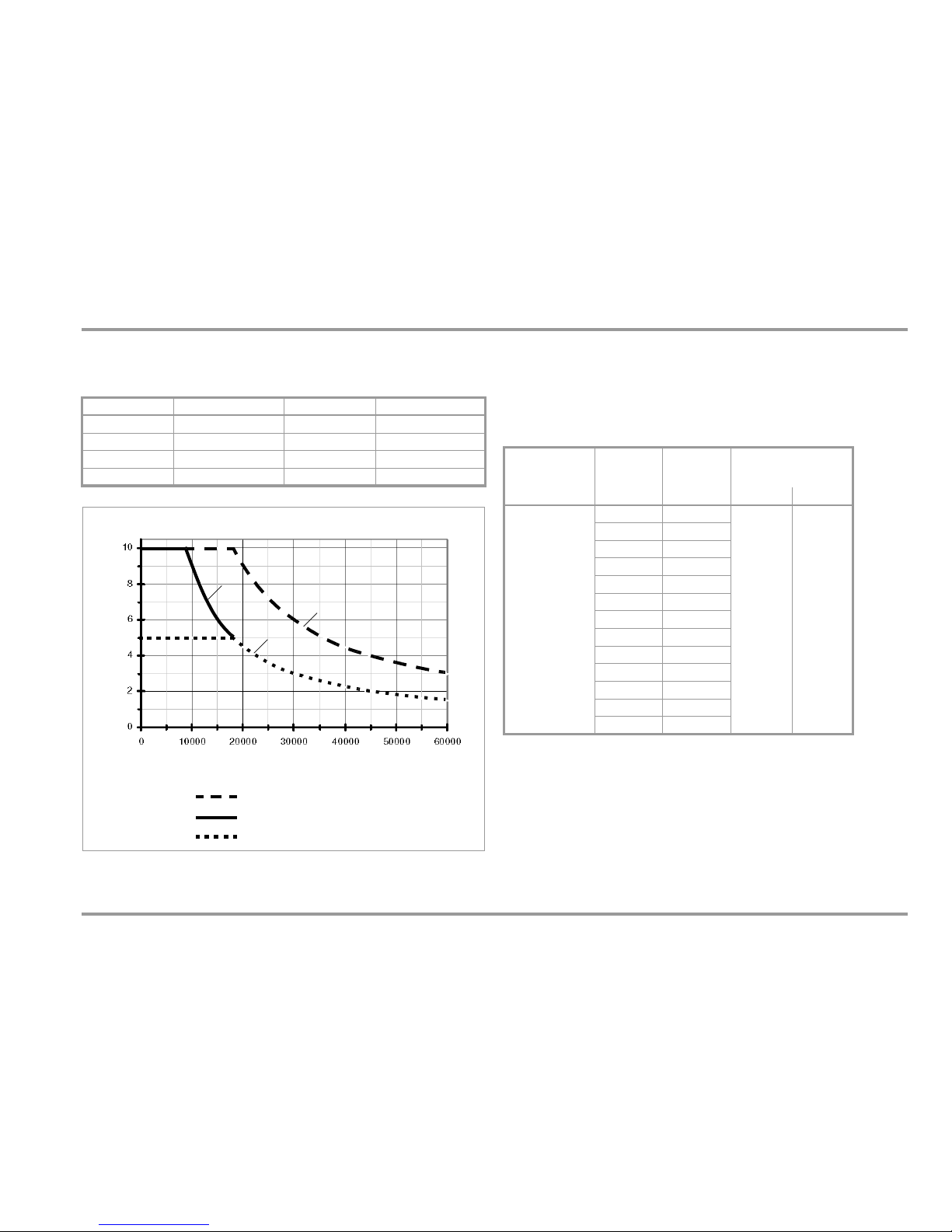
GMC-I Messtechnik GmbH 79
Technical Data
Crest Factor CF
Measuring range: 1.0
CF 11.0, resolution: 0.1
Typical (not specified) maximum deviation:
Above figure: Influence of Crest Factor on Display Range
Additional error caused by the signal’s crest factor:
1,5 < CF 3 1% rdg.
3 < CF 5 3% rdg.
Power Measurement (measuring ranges for a current clamp factor of 1)
– Single-Phase Measurement for Direct and Alternating Current
1
Ranges achieved with current clamp only
2
Off-time > 30 min. and TA 40 °C
Frequency CF 3.0 3.0 < CF 5.0 5.0 < CF 10.0
10 to 70 Hz 02 0.2 0.5
70 to 440 Hz 02 0.5 Not valid
440 Hz to 1 kHz 05 Not valid Not valid
> 1 kHz Not valid Not valid Not valid
Maximum Permissible Crest Factor
Displayed Value [counts]
Curve 1: range from 0.6 to 60 V, 0.6 mA to 10 A
1
Curve 2: 600 V range
Curve 3: power measurement
3
2
Permissible Crest Factor for Voltage and Current
Measuring
Function
Measuring
Range
Resolution at
Upper Range
Limit
Overload Capacity
at 0 ... + 40 C
36,000 counts Value Time
W, VAr, VA
360 W10nW
V: 600 V
A: 10 A
DC
AC
TRMS
sine
V
continuous
10 A: 5 min.
2
16 A: 30 sec.
2
3.6 mW 100 nW
36 mW 1 W
360 mW 10 W
3.6 W 100 W
36 W 1 mW
360 W 10 mW
600 W 100 mW
3.6 kW 100 mW
6kW 1 W
36 kW
1
1W
360 kW
1
10 W
3600 kW
1
100 W
Page 80

80 GMC-I Messtechnik GmbH
Technical Data
Intrinsic Uncertainty and Frequency Influence for Power and Energy
Measurement
1
Not applicable in mV range
Display range
– Current and voltage: 6000 digits
– Apparent, reactive and active power: 36,000 digits
– Power factor: 100 digits
Intrinsic error: stable sinusoidal voltage, stable sinusoidal current, mean
voltage value: max. 10% amplitude. U > 9% of the upper range limit is
usually the case during normal operation due to auto-ranging, except in
the smallest range.
Bandwidth up to 1 kHz; signal components of higher frequency are clip-
ped by input filters.
Note:
Power is measured with a separate measurement circuit: As a result,
specified accuracies for voltage and current measurement do not
correspond with the specified values for the respective measuring
functions. Principally, DC voltage linearity is only assured with voltages
of 0.15 V or 10% of the upper range limit.
Additional deviation for U, I during power measurement
with higher crest factor, f = 0 … 65 Hz:
CF = 2: -0.3% rdg., CF = 3: -0.9% rdg.,
CF = 4: -1.5% rdg., CF = 5: -2.5% rdg.
Square-cycle signal 10 to 65 Hz to U or I:
additional intrinsic uncertainty of +0% / -0.7% rdg.
Mains Monitoring / Mains Disturbance Recording
* Absolute value of the transients is limited to approximately 1000 V by
input protection.
Internal clock
Time format DD.MM.YYYY hh:mm:ss
Resolution 0.1 s
Accuracy 1 min./month
Temp. influence 50 ppm/K
Reference Conditions
Ambient temperature +23 C 2K
Relative humidity 40 ... 75%
(no condensation allowed)
Meas. quantity frequency 45 ... 65 Hz
Meas. quantity waveform Sine
Battery voltage 1.8 V ... 3.2 V
Measured
Quantity
Measuring
Range
Intrinsic Uncertainty ±(... % rdg + ... d)
DC 10 Hz ... 65 Hz 65 Hz ... 1 kHz
Voltage,
auxiliary display
U 0.1 x Umax
and U 0.15 V
0.5 + 10 0.3 + 10 0.4 + 10
1
Current,
auxiliary display
I 0.01 x Imax 0.2 + 5 0.1 + 5 0.9 + 10
Power factor 1 d 1 d + 1 d
1
Apparent power 1.0 + 20 0.4 + 20 1.3 + 20
1
Active power
|PF| 0.4
|PF| <0.4
1.0 + 20
—
0.4 + 20
1.0 + 20
1.5 + 20
1
3.0 + 20
1
Reactive power |PF| 0.8 — 1.0 + 20 3.0 + 20
1
Typ e of
Disturbance
Measuring Range Resolution
(display)
Intrinsic Uncertainty under
Reference Conditions with
Fixed Frequency of 50/60 Hz
Pulse Time
Over/
undervoltage
6 ... 600 V 60,000
digits
Dip/swell 6 ... 600 V 6000 digits ±(1% rdg. + 1% MR) 1 half-cycle
Peak 6 ... 600 V 6000 digits ±(1% rdg. + 2% MR) 1 ms
Transient 200 ... 1000 V * 10 V 50 V 0.5 ... 5 s
Page 81

GMC-I Messtechnik GmbH 81
Technical Data
Influencing Quantities and Influence Error
1
The 60 mV DC range and thermocouple measurement are sensitive to temperature
fluctuation: For this reason, specified values are not valid until 30 minutes after
ambient temperature has stabilized.
2
Power limiting: frequency x voltage max. 6 x 10⁶ V x Hz for U > 100 V
3
The accuracy specification for frequency response is valid as of a display value of
10% of the measuring range for both measuring modes with the TRMS converter
in the A AC and A (AC+DC) ranges.
4
Frequency response up to 100 kHz, > 60 kHz plus 5%
Influencing
Quantity
Sphere of
Influence
Measured Quantity/
Measuring Range
Influence Error per 10 K
(...% rdg. + ... d)
Temperature
0 C ... +21 C
and
+25 C... +40 C
60 mV
1
0.2 + 5
600 mV ... 600 V 0.1 + 5
600 mV 0.3 + 20
V , 6 ... 600 V 0.2 + 10
600 ... 60 M, nS 0.2 + 5
A , , 0.2 + 10
60 nF ... 6 F, km 1 + 5
60, 600 F3 + 5
Hz, dB 0.2 +10
Diode measurements 0.3 + 5
RPE measurement 1 + 10
Pt100 / Pt1000 0.5 + 10
Type K thermocouple
1
0.2 + 10
Power measurement: V 0.3 + 10
Power measurement: A 0.2 + 5
W, VA, Wh, VAh 0.5 + 10
Influen-
cing
Quantity
Measured Qty. /
Measuring Range
Sphere of Influence
Intrinsic Uncertainty
3
... % rdg. + ... d)
Frequency
V
AC
600.00 mV
> 15 Hz ... 45 Hz 3 + 30
>65Hz... 1kHz 2 + 30
> 1 kHz ... 20 kHz 3 + 30
> 20 kHz ... 100 kHz
4
3.5 + 30
4
6.0000 V
...
60.00 V
> 15 Hz ... 45 Hz 2 + 30
>65Hz... 1kHz 1 + 30
> 1 kHz ... 20 kHz 3 + 30
> 20 kHz ... 100 kHz
4
3.5 + 30
4
600.00 V 2
> 15 Hz ... 45 Hz 2 + 30
>65Hz... 1kHz 1 + 30
> 1 kHz ... 20 kHz 3 + 30
A
AC
600.00 mA
...
10.0000 A
> 15 Hz ... 45 Hz
3 + 25
> 65 Hz ... 10 kHz
Influencing
Quantity
Sphere of
Influence
Measured Quantity Influence Error
Relative
humidity
75%
3 days
instrument off
V A, , F, Hz, dB, C 1 x intrinsic uncertainty
Battery voltage 1.8 ... 3.2 V V A, , F, Hz, dB, C
Included in
intrinsic uncertainty
Page 82

82 GMC-I Messtechnik GmbH
Technical Data
Response Time (after manual range selection)
Data Interface
Type
Optical via infrared light through the housing
Data transmission Serial, bidirectional (not IrDa compatible)
Protocol Device specific
Baud rate 38,400 baud
Functions – Select/query measuring functions
and parameters
–
Query momentary measurement data
– Read out stored measurement data
The USB X-TRA plug-in interface adapter (see accessories) is
used for adaptation to the PC’s USB port.
Internal Measured Value Storage
Memory capacity 16 MBit for approx. 300,000 measured
values with indication of date and time
Influencing
Quantity
Sphere of Influence
Measured Quantity/
Measuring Range
Damping
Common mode
interference
voltage
Interference quantity max. 600 V V > 120 dB
Interference quantity max. 600 V
50 Hz ... 60 Hz, sine
6 V , 60 V > 80 dB
600 V > 70 dB
Series-mode
interference
voltage
Interference quantity V ,
respective nominal value of the
measuring range,
max. 600 V , 50 Hz ... 60 Hz, sine
V> 50dB
Interference quantity max. 600 V V > 100 dB
Measured Quantity/
Measuring Range
Digital Display
Response Time
Measured Quantity
Jump Function
V, V, dB
AV , A
1.5 s
From 0 to 80%
of upper range limit value
600 ... 6 M 3s
From to 50%
of upper range limit value
nS, RPE 3 s
60 M 8s
Continuity (acoustic signal) < 50 ms
C (Pt100) Max. 3 s
1.5 s
60 nF ... 600 FMax. 2s
From 0 to 50%
of upper range limit value
> 10 Hz 1.5 s
Page 83

GMC-I Messtechnik GmbH 83
Technical Data
Power Supply
Battery 2 each 1.5 V AA batteries,
alkaline manganese per IEC LR6
(2 each 1.2 V NiMH rechargeable batteries
also possible)
Service life With alkaline manganese: approx. 120 hrs.
Battery Indicator Battery capacity display with battery
symbol in 4 segments: .
Querying of momentary battery voltage via
menu function.
Power OFF function The multimeter is switched off
automatically
:
– When battery voltage drops below
approx. 1.8 V
– If none of the keys or the rotary switch
are activated for an adjustable duration
of 10 to 59 min. and the multimeter is
not in the continuous operation mode
(assuming the instrument is not set to
power measurement or mains analysis)
Power pack socket
If the NA X-TRA power pack has been
plugged into the instrument, the batteries
are disconnected automatically.
Rechargeable batteries can only be
recharged externally. Power pack voltage:
5.1 V 0.2 V
Display
Transreflective LCD
panel (65 x 36 mm)
with display of up
to 3 measured
values, unit of
measure, type of
current and various
special functions.
Background illumination
LED fiber-optic background illumination is switched off approximately 1 minute after it has been activated. If necessary, automatic deactivation of background illumination can be disabled with
the appropriate parameter setting or via the interface.
Display / char. height 7-segment characters
Main display: 13 mm
Auxiliary displays: 7.5 mm
Number of places 60,000 counts/steps
Overflow display “OL” is displayed as of 61,000 + 1 digits
Polarity display “–” sign is displayed if plus pole is
connected to “”
Sampling rate 10 or 40 measurements per second
with
the Min-Max function except for the
capacitance, frequency, duty cycle and power
measuring functions, 2000 measurements per
second for fast DC measurement
Refresh rate
V (DC, AC+DC), A, , ,
EVENTS AC/DC, count
2 per second
Hz, C (Pt100, Pt1000)
1 to 2 per second
C (J, K) 0.5 per second
Page 84

84 GMC-I Messtechnik GmbH
Technical Data
Acoustic Signals
For voltage Intermittent signal at above 600 V
For current Intermittent signal at above 10 A
Continuous signal at above 16 A
Fuse
Fuse link FF (UR) 10 A/1000 V AC/DC;
10 mm x 38 mm; breaking capacity of
30 kA at 1000 V AC/DC;
protects the current measurement input in
the 600 A to 10 A ranges
Electrical Safety
Per IEC 61010-1:2001/VDE 0411-1:2002
Protection class
II
Measuring category CAT III CAT IV
Operating voltage 600 V 300 V
Pollution degree
2
Test v o l t ag e
5.2 kV~
Electromagnetic Compatibility (EMC)
Interference emission EN 61 326-1: 2006 class B
Interference immunity EN 61 326-1: 2006
EN 61326-2-1: 2006
Ambient Conditions
Accuracy range 0C to +40C
Op. temp. range
T
A
10C to +50C *
Storage temp. range 25C to +70C (without batteries)
Relative humidity 40 to 75%, no condensation allowed
Elevation To 2000 m
Deployment
Indoors, except within specified ambient
conditions
* Exception: measurement of current > 10 to 16 A, operation at up to 40 C
Mechanical Design
Housing Impact resistant plastic (ABS)
Dimensions 200 x 87 x 45 mm
(without rubber holster)
Weight Approx. 0.4 kg with batteries
Protection Housing: IP 52
(pressure equalization via housing)
Table Excerpt Regarding Significance of
IP-Codes
IP XY
(1
st
digit X)
Protection Against Foreign
Object Entry
IP XY
(2nd digit Y)
Protection Against
Penetration by Water
5 Dust protected 2 Dripping (at angle of 15°)
Page 85

GMC-I Messtechnik GmbH 85
Maintenance – Calibration
9 Maintenance and Calibration
Attention!
!
Disconnect the instrument from the measuring circuit before
opening the battery compartment lid or fuse cover in order
to replace batteries or fuses!
9.1 Displays – Error Messages
9.2 Batteries
Note
Removing the Batteries During Periods of Non-Use
The integrated quartz movement draws power from the batteries even when the instrument is switched off. It’s advisable to remove the batteries during long periods of non-use
for this reason (e.g. vacation). This prevents excessive
depletion of the batteries, which may result in damage under
unfavorable conditions.
Note
Battery Replacement
Stored measurement data are not lost when the batteries
are replaced. The selected operating parameters remain in
memory, although date and time must be reentered.
Charge Level
The current battery charge level can be queried in the “1nfo” menu:
1nFo bAtt: 2.75 V.
Make sure that no battery leakage has occurred before initial startup, as well as after long periods of storage. Continue to inspect the
batteries for leakage at short, regular intervals.
If battery leakage has occurred, carefully and completely clean the
electrolyte from the instrument with a damp cloth, and replace the
battery before using the instrument.
If the “ ” symbol appears at the display, the batteries should be
replaced as soon as possible. You can continue working with the
instrument, but reduced measuring accuracy may result.
The instrument requires two 1.5 V batteries in accordance with
IEC R 6 or IEC LR 6, or two equivalent rechargeable NiMH batteries.
Message Function Meaning
FUSE
Current measurement Blown fuse
In all operating modes Battery voltage has fallen below 1.8 V
0 L
Measuring Indicates overflow (overload)
u r
Measuring Indicates that the measuring range has been
fallen short of (under range)
MEASURE
SETUP
FUNC
ENTER
Page 86

86 GMC-I Messtechnik GmbH
Maintenance – Calibration
Replacing the Batteries
Attention!
!
Disconnect the instrument from the measuring circuit before
opening the battery compartment lid in order to replace the
batteries.
Ð Set the instrument face down onto the working surface.
Ð Turn the slotted screw on the lid with the battery symbols
counterclockwise.
Ð Lift off the lid and remove the batteries from the battery com-
partment.
Ð Insert two new 1.5 V mignon batteries into the battery com-
partment, making sure that the plus and minus poles match up
with the provided polarity symbols.
Ð When replacing the battery compartment lid, insert the side
with the guide hooks first.
Tighten the screw by turning it clockwise.
Ð Please dispose of depleted batteries in accordance with envi-
ronmental protection regulations!
9.3 Fuse
Testing the Fuse
The fuse is tested automatically:
• When the instrument is switched on with the rotary switch in the
A position
• When the instrument is already on and the rotary switch is
turned to the A position
• In the active current measuring range when voltage is applied
If the fuse is blown or has not been inserted, “FuSE” appears at the
digital display. The fuse interrupts the current measuring ranges. All
other measuring ranges remain functional.
Replacing the Fuse
If a fuse should blow, eliminate the cause of overload before
placing the instrument back into service!
Attention!
!
Disconnect the instrument from the measuring circuit before
opening the fuse cover in order to replace the fuse!
Ð Set the instrument face down onto the working surface.
Ð Turn the slotted screw on the cover with the fuse symbol coun-
terclockwise.
Ð Lift off the cover and pry the fuse out using the flat side of the
fuse cover.
Ð Insert a new fuse. Make sure that the fuse is centered, i.e.
between the tabs at the sides.
Ð When replacing the fuse cover, insert the side with the guide
hooks first.
Tighten the screw by turning it clockwise.
Ð Dispose of the blown fuse with the trash.
Blown Fuse
fuse
A
DC
Page 87

GMC-I Messtechnik GmbH 87
Maintenance – Calibration
Attention!
!
Use specified fuses only!
If fuses with other blowing characteristics, other current ratings or other breaking capacities are used, the operator is
placed in danger, and protective diodes, resistors and other
components may be damaged.
The use of repaired fuses or short-circuiting the fuse holder
is prohibited.
9.4 Housing Maintenance
No special maintenance is required for the housing. Keep outside
surfaces clean. Use a slightly dampened cloth for cleaning. Avoid
the use of cleansers, abrasives or solvents.
9.5 Return and Environmentally Sound Disposal
The instrument is a category 9 product (monitoring and control
instrument) in accordance with ElektroG (German electrical and
electronic device law). This device is not subject to the RoHS
directive.
We identify our electrical and electronic devices (as of
August 2005) in accordance with WEEE 2002/96/EC
and ElektroG using the symbol shown at the right per
DIN EN 50419.
These devices may not be disposed of with the trash.
Please contact our service department regarding the return of old
devices (see address on page 4).
If you use batteries or rechargeable batteries in your instrument or
accessories which no longer function properly, they must be duly
disposed of in compliance with the applicable national regulations.
Batteries or rechargeable batteries may contain harmful substances or heavy metal such as lead (PB), cadmium (CD) or mercury
(Hg).
They symbol shown to the right indicates that batteries or
rechargeable batteries may not be disposed of with the
trash, but must be delivered to collection points specially
provided for this purpose.
9.6 Recalibration
The respective measuring task and the stress to which your measuring instrument is subjected affect the ageing of the components and may result in deviations from the guaranteed accuracy.
If high measuring accuracy is required and the instrument is frequently used in field applications, combined with transport stress
and great temperature fluctuations, we recommend a relatively
short calibration interval of 1 year. If your measuring instrument is
mainly used in the laboratory and indoors without being exposed
to any major climatic or mechanical stress, a calibration interval of
2-3 years is usually sufficient.
During recalibration* in an accredited calibration laboratory
(DIN EN ISO/IEC 17025) the deviations of your instrument in relation to traceable standards are measured and documented. The
deviations determined in the process are used for correction of
the readings during subsequent application.
Pb Cd Hg
Page 88

88 GMC-I Messtechnik GmbH
Maintenance – Calibration
We are pleased to perform DKD or factory calibrations for you in
our calibration laboratory. Please visit our website at
www.gossenmetrawatt.com ( Services DKD Calibration
Center or FAQs Calibration questions and answers).
By having your measuring instrument calibrated regularly, you fulfill the requirements of a quality management system per
DINENISO9001.
* Verification of specifications or adjustment services are not part of the
calibration. For products from our factory, however, any necessary adjustment is frequently performed and the observance of the relevant
specification is confirmed.
9.7 Manufacturer’s Guarantee
All METRA HIT measuring and calibration instruments are guaranteed for a period of 3 years after date of shipment. The manufacturer’s guarantee covers materials and workmanship. Damages
resulting from use for any other than the intended purpose, as well
as any and all consequential damages, are excluded.
Calibration is guaranteed for a period of 12 months.
Page 89

GMC-I Messtechnik GmbH 89
Accessories
10 Accessories
10.1 General
The extensive accessories available for our measuring instruments
are checked for compliance with currently valid safety regulations
at regular intervals, and are expanded as required for new applications. Currently up-to-date accessories which are suitable for your
measuring instrument are listed at the following web address along
with photo, order number, description and, depending upon the
scope of the respective accessory, data sheet and operating instructions: www.gossenmetrawatt.de ( Measuring Technology –
Portable Digital Multimeters METRA HIT ... Multimeter
Accessories).
10.2 Technical Data for Measurement Cables
(KS17-2 safety cable set included with instrument)
Electrical Safety
Max. rated voltage
Measuring category 1000 V CAT II I, 600 V CAT IV
Max. rated current: 16 A
Ambient Conditions (EN 61010-031)
Temp era tu re –20 C ... + 50 C
Relative Humidity Max. 80%
Pollution Degree
2
Application
In conformity with standard DIN EN 61010-031, measurements in
an environment according to measuring category III and IV may
only be performed with the safety caps applied to the test probes of
the measurement cables.
For establishing contact in 4 mm jacks you have to remove the
safety cap by levering out the snap lock of the safety cap with another sharp object (e. g. the second test probe).
10.3 NA X-TRA Power Pack (Z218G: not included)
Use power packs from GMC-I Messtechnik GmbH only in combination with your instrument. This assures operator safety by
means of an extremely well insulated cable, and safe electrical isolation (nominal secondary ratings: 5 V / 600 mA). Installed batteries
are disconnected electronically if the power pack is used, and
need not be removed from the instrument.
Note
Use of the power pack may result in significant deviations
during capacitance measurement and in the 60 M range!
Page 90

90 GMC-I Messtechnik GmbH
Accessories
10.4 PMA 16 Power Measuring Adapter (Z228A: not included)
The PMA 16 power measuring adapter is an intermediate plug for
safe, trouble-free measurement of power consumption of singlephase consumers connected by means of a plug. The power consumer’s protective conductor remains functional during measurement.
10.5 Interface Accessories (not included)
USB X-TRA Bidirectional Interface Adapter (Z216C)
E series METRAHIT multimeters which are equipped with a serial
IrDa interface can be connected to a USB port at a PC with the
adapter. The adapter allows for data transmission between the
multimeter and the PC.
METRAwin10 PC Analysis Software
METRAwin10 PC software is a multilingual, measurement data log-
ging program for recording, visualizing, evaluating and documenting measured values from METRAHIT multimeters.
The following conditions must be fulfilled in order to allow for use of
METRAwin10:
Hardware, Software and Driver
• IBM compatible Windows PC, 200 MHz Pentium processor or
faster with at least 64 MB RAM
• SVGA monitor with at least 1024 x 768 pixels
• Hard disk with at least 40 MB available memory capacity
•CD ROM drive
• Microsoft compatible mouse
• Windows supported printer
• One USB port for use of the USB X-TRA
– with installed driver USB2COM (virtual COM interface) for
Windows 2000, XP and VISTA
or
– with Driver Control for Windows XP, VISTA and 7.
COM
V
Tem p
mA A
N
PE
L
Load
PMA16
RedBlue
VA
Black
Page 91

GMC-I Messtechnik GmbH 91
Accessories
Page 92

92 GMC-I Messtechnik GmbH
Glossary
11 Glossary – Abbreviations of Measuring Functions and Measuring Parameters with their Meanings
Descriptions of the following measuring functions and their use
are included in section 5. Descriptions of the following measuring
parameters and their settings are included in section 6.
Descriptions of device parameters and their settings (which are
not listed here) are included in section 6.
Abbreviation
(Sub) Menu
Parameter
Meaning General Description
Description Specifically for this Instrument
Application
Chapter / Page
Switch
Position /
Menu
CAP Scaling factor A scaling factor (capacitive linear electric constant) must be entered in order to be able to
measure cable length in meters or kilometers.
Cable length
measurement
section 5.6
m
SEt menu
CF Crest factor Relationship of peak value to TRMS value.
Measuring range: 1.0 CF 11.0
Voltage measurement
page 25
Current measurement
page 52
V, A
CLiP Current clamp factor When a current clamp sensor or transformer is connected to the system multimeter (V or
mA/A input) all current displays appear with the correct value in accordance with the selected
transformation ratio.
Current clamp
measurement
section 5.8.2
and section 5.8.3
V, A
SEt menu
dB Voltage level Voltage level measurement is used in order to
ascertain overall attenuation or boosting of a
transmission system.
Where U
1
= U
REF
= dbrEF (reference level).
Display value > 0 dB: boosting; display value < 0 dB: attenuation
Parameter: dbrEF
Alternating voltage level measurement
page 32
dB
SEt menu
dbrEF Reference level Reference value for alternating voltage level measurement (see dB).
dEMAnd tiME Time interval for mean
value generation
This parameter specifies the observation time period for mean value generation during power
measurement (see page 50). Acquisition is synchronous to clock time, for which reason the first
mean value usually does not span the entire specified duration.
Memory mode operation for power and
energy measurement
section 4.5.2
W
SEt menu >
EnErGY
diP Voltage drop If the TRMS half-wave value falls short of the specified diP LiMit value, a voltage drop (dip) is
detected. Parameter: diP LiMit
Power disturbance
analysis
section 5.1.3
PQ
SEt menu >
MainS
diP LiMit Voltage drop limit value See diP
Unit of measure in digits, 60,000 = full measuring range
Voltagelevel dB 20
U
2
U
1
-----log=
Page 93

GMC-I Messtechnik GmbH 93
Glossary
EVEntS Submenu for events
recording parameters
An event is recorded whenever at least one measured value has fallen short of the L-trig threshold
for at least one second, and subsequently at least one measured value has exceeded the H-trig
threshold for at least one second.
Parameters: L-TriG, H-TriG and rAtE DC
Events recording
page 28
V
SEt menu >
EVEntS >
triG
HArM Submenu for
harmonics parameters
Parameters menu for harmonic analysis:
Included parameters: HArM.F (fundamental frequency), U.rAnGE (voltage measuring range) and
I.rAnGE (current measuring range).
Harmonic analysis
section 5.1.5 SEt menu >
HArM
HArM.F Fundamental frequency See HArM
Line frequency of the fundamental frequency (here: 16.7, 50, 60 or 400 Hz)
HiVolt LiMit Upper trigger threshold The threshold value for overvoltage (HiVolt LiMit) while monitoring the TRMS voltage value can be
entered here in digits. The full measuring range corresponds to 60,000 digits.
Power disturbance
analysis
section 5.1.3
PQ
SEt menu >
MainS
H_triG Upper trigger threshold See EVEntS Events recording
page 28
V
SEt menu >
EVEntS >
triG
H_triG Upper trigger threshold See StorE Selective memory
mode operation
section 4.5
All
StorE menu
> triG
HYSt Hysteresis The hysteresis setting allows for efficient use of memory space. During memory mode operation,
new measured data are only saved to a new memory block if they deviate from the previously
stored value by an amount which exceeds the selected hysteresis value.
Memory mode
operation
section 4.5
All
SEt menu >
StorE
I.rAnGE Current range of the
harmonics
See HArM
Current range of the harmonics (here: auto, 600 μA, 6, 60, 600 mA, 6 A, 10 A)
Note: Clamp factor is not taken into consideration!
Harmonic analysis
section 5.1.5
A
SEt menu >
HArM
LoVolt LiMit Lower trigger threshold The threshold value for undervoltage (LoVolt LiMit) while monitoring the TRMS voltage value can
be entered here in digits. The full measuring range corresponds to 60,000 digits.
Power disturbance
analysis
section 5.1.3
PQ
SEt menu >
MainS
L_triG Lower trigger threshold See EVEntS Events recording
page 28
V
SEt menu >
EVEntS >
triG
Abbreviation
(Sub) Menu
Parameter
Meaning General Description
Description Specifically for this Instrument
Application
Chapter / Page
Switch
Position /
Menu
Page 94
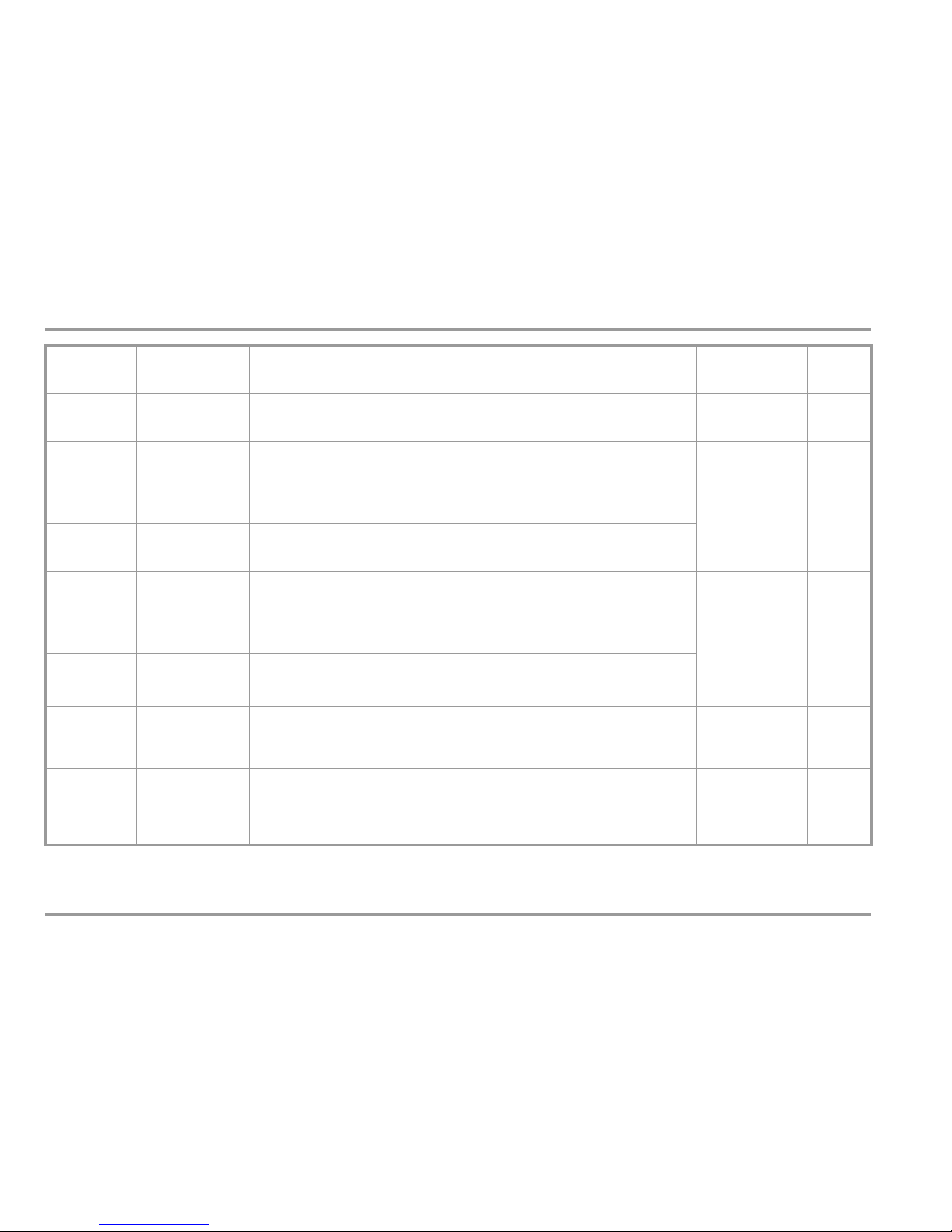
94 GMC-I Messtechnik GmbH
Glossary
L_triG Lower trigger threshold See StorE Selective memory
mode operation
section 4.5
All
StorE menu
> triG
MAinS Submenu for power
disturbance analysis
parameters
Parameters:
MAinS.F, MAinS rAnGE, LoVolt LiMit, HiVolt LiMit, diP LiMit, SWELL LiMit, PEAK LiMit, trAnS LiMit
Power disturbance
analysis
section 5.1.3
PQ
SEt menu >
MainS
MAinS rAnGE Line voltage
measuring range
Here: The 6 V, 60 V or 600 V range (default) can be selected as the voltage measuring range.
MAinS.F Line voltage frequency Selection of the measuring signal line frequency is required for the calculation of the TRMS
half-wave value: 50 or 60 Hz. It determines whether a TRMS value is generated every 8.33 ms,
or every 10 ms.
nS Siemens Unit of measure for electrical conductivity in the SI units system.
Reciprocal value of electrical resistance: S = 1/Ohm = A/V, nS = nanoSiemens
Conductivity
measurement
section 5.2
Ohm
Peak Peak value If the momentary voltage value exceeds the value specified here (regardless of polarity), an
exceeded limit value is recorded (PEAK LiMit).
Power disturbance
analysis
section 5.1.3
PQ
SEt menu >
MainS
PEAK LiMit Peak limit value See PEAK
PF Power factor Value: Relationship of active power value P to apparent power S
Sign: 1: no phase shifting; –(0 ... 0.99): capacitive; +(0 ... 0.99): inductive
Power measurement
section 5.7
W
r_SL Low-resistance
measurement
The resistance of a protective conductor connection limits, for example, the length of an extension
cable or a cable reel, or may not exceed a specified limit value. The same applies to resistance
between housing and mains plug or device plug. The limit value can be set within a range of 1 to
60 ohms.
Resistance
measurement
section 5.2
Ohm
rAtE Sampling rate The sampling rate specifies the time interval after which the respective measured value is
transmitted to the interface, or to measured value memory.
Memory mode
operation
section 4.5
Interface operation
section 6.4.7
All
StorE menu
Abbreviation
(Sub) Menu
Parameter
Meaning General Description
Description Specifically for this Instrument
Application
Chapter / Page
Switch
Position /
Menu
Page 95

GMC-I Messtechnik GmbH 95
Glossary
StorE Main memory for
memory mode
operation
Parameters: HYSt, rAtE, Sto-ou, Sto-in, L_triG, H_triG, t.StorE
Power and energy measurement in memory mode: section 4.5.2
Scope of stored values for power and energy measurements: section 6.4.4
Mains disturbance recording in memory mode: section 5.1.4
Memory mode
operation
section 4.5
All
StorE menu
SWELL Overvoltage If the TRMS half-wave value exceeds the specified limit, a brief overvoltage (swell) is detected.
Parameter: SWELL LiMit
Power disturbance
analysis
section 5.1.3
PQ
SEt menu >
MainS
SWELL LiMit Overvoltage limit value See SWELL
t
E/tP
Duty cycle The ratio of pulse duration to pulse period is measured with periodic square-wave signals and is
displayed as a percentage.
Duty cycle
measurement
section 5.1.6
%
THD Total harmonic
distortion
As a standard feature during harmonic analysis, THD is displayed in accordance with the
equation: “THD = total TRMS value of harmonics ÷ TRMS value of the fundamental frequency”.
As opposed to this, harmonic distortion of the individual harmonics appears in the displays for the
individual harmonics.
“Distortion component = TRMS value of the harmonic ÷ TRMS value of the fundamental
frequency.
Harmonic analysis (voltage)
section 5.1.5
Harmonic analysis
(current)
section 5.8.2 and
section 5.8.3
, A
trAnS Transients Steep sloped voltage peaks; parameter: trAnS LiMit Power disturbance
analysis
section 5.1.3
PQ
SEt menu >
MainS
trAnS LiMit Transients limit value A level can be set here as of which a voltage transient is recorded. This is a polarity independent
entry relative to the momentary value. The smallest value is 200 V. Regardless of the selected
measuring range, acquisition always takes place within a range of 200 … 1000 V.
t.StorE Recording time Limiting of recording duration (hh:min:ss) to a maximum of 99 hours, 59 minutes and 59
seconds, or unlimited recording time: parameter = on.
Memory mode
operation
section 4.5
All
StorE menu
U.rAnGE Voltage range of the
harmonics
See HArM
Voltage range of the harmonics (here: auto, 600 mV, 6 V, 60 V, 600 V)
Note: Clamp factor is not taken into consideration!
Harmonic analysis
section 5.1.5 SEt menu >
HArM
Abbreviation
(Sub) Menu
Parameter
Meaning General Description
Description Specifically for this Instrument
Application
Chapter / Page
Switch
Position /
Menu
Duty cycle (%) =
Pulse duration (t
E
)
Pulse period (t
P
)
100
Page 96

96 GMC-I Messtechnik GmbH
Index
12 Index
0.diSP ................................................................... 65
A
Active Power ........................................................ 47
Addr ...................................................................... 76
APoFF ................................................................... 64
Apparent Power ................................................... 47
Automatic Shutdown
Disabling ..................................................... 15
Specifying a Time ....................................... 15
AUTO-Range Function ......................................... 16
B
Batteries
Charge Level Display .................................. 11
Charge Level Query .............................. 63, 85
Periods of Non-Use .................................... 85
Replacement ............................................... 86
bEEP ..................................................................... 66
C
Cable Length ........................................................ 45
Cable Length Measurement ................................ 46
Cable Resistance ................................................. 44
CAP ....................................................................... 66
Capacitance Measurement ................................. 45
Clear
Memory ....................................................... 23
CLiP ...................................................................... 66
Conductivity .......................................................... 39
Continuity Test ..................................................... 41
Crest Factor Display
Current
........................................................ 53
Voltage .........................................................27
Current Clamp Sensor .................................... 56, 57
Current Measurement
Notes
...........................................................52
Scope of Functions .....................................52
D
dAtE ................................................................. 63, 64
dbrEF ..................................................................... 66
Default Settings .................................................... 74
dEMAnd tiME ........................................................ 68
Device Returns .....................................................87
Diode Test ............................................................. 42
Display Illumination .............................................. 14
Duty Cycle Measurement ..................................... 38
E
Error Messages ....................................................85
EVEntS ............................................................28, 65
F
Firmware Version ................................................. 63
Fuse
Replacement ............................................... 86
G
Glossary ................................................................ 92
H
HArM .....................................................................71
Harmonic Analysis ................................................ 54
HYSt ......................................................................73
I
Interfaces
Accessories
.................................................90
States ...........................................................11
irStb .......................................................................76
L
Level Measurement (dB) ......................................32
Low-Pass Filter .....................................................30
Low-Resistance Measurement ............................39
M
MAinS ....................................................................69
Mains Disturbance Recording ..............................33
Mains Monitoring ..................................................33
Maintenance
Housing ........................................................87
Manufacturer’s Guarantee ...................................88
Measured Value Storage
DATA Function .............................................20
Min-Max Values ..........................................21
Measurement Cables ...........................................89
Measuring Category
Significance
...................................................7
Measuring Range Selection
Automatic .....................................................16
Manual .........................................................16
Memory
Ending Recording ........................................23
Querying Occupancy ...................................23
Start Recording ............................................22
Minimum Breaking Capacity ................................52
Page 97

GMC-I Messtechnik GmbH 97
Index
O
OCCUP .................................................................. 63
Overview
Keys and Connections ................................ 10
Parameters .................................................. 62
Overvoltage .......................................................... 34
P
Peak Value Monitoring ......................................... 17
Potentially Explosive Atmospheres ........................ 7
Power Factor ........................................................ 47
Power Pack
Accessories ................................................. 89
Connector Socket Location ........................ 13
Initial Start-Up ............................................. 14
Product Support ..................................................... 3
Product Support Hotline ......................................... 3
Q
Quick Measurements (MAN or DATA function) .. 18
R
r_SL ...................................................................... 66
Rapid Momentary Value Acquisition for U DC and I
DC ......................................................................... 24
rAtE ....................................................................... 72
Reactive Power ..................................................... 47
Recalibration ......................................................... 87
Recalibration Service ............................................. 4
Relative Measurements .......................................18
Remote ................................................................. 43
Repair and Replacement Parts Service ................. 4
Reset ..................................................................... 74
Resistance ............................................................ 39
S
Safety Precautions ..................................................7
Sampling Rate (rAtE parameter) .......................... 72
Scaling Factor .......................................................46
Scope of Delivery .................................................... 2
Setting the Reference Value ................................19
Shutdown
Automatic (APoFF parameter) ....................64
Automatic (function) .................................... 15
Software Enabling ...................................................3
Storage Rate (rAtE parameter) ............................. 72
StorE ......................................................................68
Switching the Instrument On
Manual ......................................................... 14
Via PC .......................................................... 14
Symbols
Digital Display ..............................................11
Instrument ...................................................13
Rotary Switch Positions ..............................12
T
tEMP intErn ...........................................................63
tEMP intErn/ExtErn ............................................... 67
tEMP unit ..............................................................66
Temperature Measurement
With Resistance Thermometers ................. 44
With Thermocouples ...................................43
tiME .................................................................63, 64
Total Harmonic Distortion THD ............................54
Transients ............................................................. 34
Transmission Rate (rAtE parameter) .................... 72
triG .........................................................................73
tStorE ....................................................................74
U
Use for Intended Purpose ...................................... 9
V
vErSion ................................................................. 63
Voltage Comparator ............................................. 31
Voltage Drop ......................................................... 34
Voltage Measurement
Notes
........................................................... 25
Scope of Functions ..................................... 25
Voltage Peaks ...................................................... 34
Voltage Transients ............................................... 70
W
WEEE Mark ........................................................... 13
Z
ZERO ..................................................................... 18
Zero Offset ........................................................... 18
Page 98

Edited in Germany · Subject to change without notice · PDF version available on the Internet
GMC-I Messtechnik GmbH
Südwestpark 15
90449 Nürnberg, Germany
 Loading...