

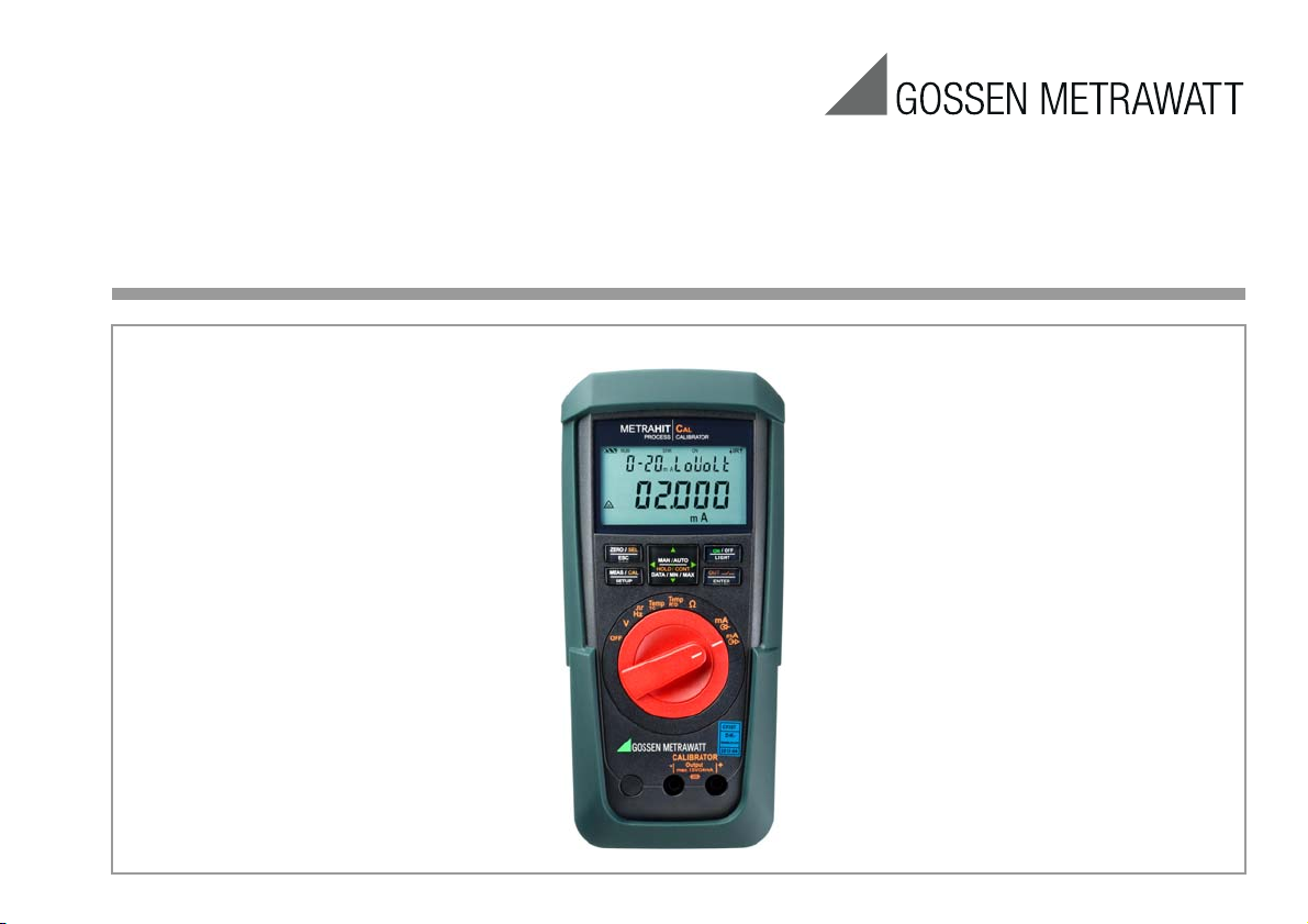
Operating Instructions
METRAHIT⏐CAL
Calibrator
3-349-442-03
11/12.15
Operating Overview – Connections, Keys, Rotary Switch, Symbols
1
3
4
14
5
6
12
10
2
12
9
13
7
Not a measurement input!
Do not apply interference voltage,
except with current sink.
!
8
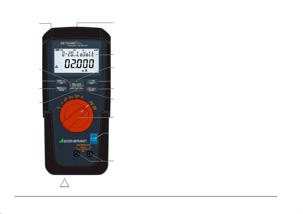
1 Display (LCD) (see page 3 for significance of symbols
2 HOLD / CONT Pause/resume ramp/interval
Increase parameter values
Mode menu:
3
ON / OFF | LIGHT
Selection of individual menu entries against direction of flow
, key for switching device and display illumination on and off
4 OUT | ENTER
OUT: Switch calibrator output on and off
Mode menu: Acknowledge entry (ENTER)
Move cursor to the right
5
SELECT RANGE operating mode: ramp function selection
6 Rotary switch for calibration functions and complete shutdown
7 DAkkS calibration mark
8 Connector jacks for calibrator output
9 HOLD / CONT Pause/resume ramp/interval
Reduce parameter values
Mode menu:
Selection of individual menu entries in direction of flow
10 MEAS/ CAL | SETUP
Key for switching back and forth between calibration and menu function
11 ZERO/ SEL | ESC
Mode menu: Exit current menu level and
return to a higher level,
exit parameters configuration
without saving data.
Pause ramp/interval.
Move cursor to the left,
12
SELECT RANGE operating mode: interval function selection
13 Power pack connector jack (accessory: NA X-TRA)
14 Infrared interface (accessory interface adapter:
USB X-TRA)
2 GMC-I Messtechnik GmbH
1 28
9
10
12
12
14
654 7
15
3
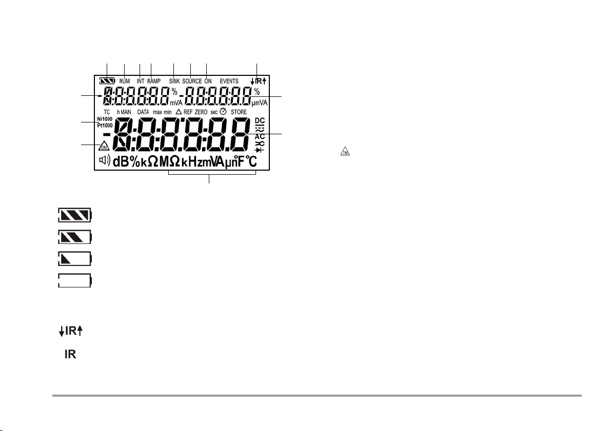
Battery full
Battery OK
Battery weak
Battery (almost) dead, U < 1.8 V
Data transmission ↓ to / ↑ from calibrator is active
IR interface in standby mode
(ready to receive starting commands)
Battery Level Indicator
Interface Indicator (with selector switch setting ≠ OFF)
Symbols used in the Digital Display 1 Battery level indicator
2 NUM: Numeric entry of the output signal
3 INT: Interval sequence active
4 RAMP: Ramp function active
5 SINK: Current sink is active
6 SOURCE: Current source is active
7 ON: The calibrator output is active
8 IR: Infrared interface display
9 Auxiliary display with decimal point and polarity display
10 Main display with decimal point and polarity display
11 Calibration unit of measure
12 : Simulator in continuous mode operation
13 Ni/Pt1000: Selected temperature sensor
14 Auxiliary display with decimal point and polarity display
GMC-I Messtechnik GmbH 3

Table of Contents
Page Page
1 Safety Features and Precautions ....................................................5
2 Initial Start-Up .................................................................................7
3 Voltage Source [V] ...........................................................................8
4
Frequency Generator (positive square-wave pulses) [Hz] ....................9
5 Resistance Simulation [Ω] ............................................................10
6 Temperature Simulation [°C / °F] ..................................................11
6.1 Temperature Simulation for Resistance Temperature Detectors – RTD setting for
temperature .................................................................................................12
Temperature Simulation for Thermocouples – TC Temperature Setting ...................12
6.2
7 Current Source and Current Sink [mA] ..........................................14
7.1 Current Sink – Simulation of a 2-Wire Transmitter ......................................... 15
7.2 Current Source ............................................................................................15
8 Interval Functions, Ramp Functions and Procedures ....................16
8.1 Interval Sequences – INT Function .................................................................16
8.2 Read-Out a Periodic Ramp – RAMP Function ..................................................19
9 Device and Calibration Parameters ...............................................21
9.1 Querying Parameters – InFo Menu ................................................................. 22
9.2 Entering Parameters – SETUP Menu ..............................................................22
9.3 Default Settings ............................................................................................23
10 Interface Operation (with selector switch setting ≠ OFF) ..............24
10.1 Activating the Interface ..................................................................................24
10.2 Configuring Interface Parameters ................................................................... 24
11 Technical Data ..............................................................................25
12 Maintenance .................................................................................29
12.1 Displays – Error Messages ........................................................................... 29
12.2 Batteries ...................................................................................................... 29
12.3 Fuses .......................................................................................................... 30
12.4 Housing Maintenance ................................................................................... 31
12.5 Return and Environmentally Sound Disposal ................................................... 31
13 Calibrator Messages .....................................................................31
14 Accessories ...................................................................................32
14.1 General ........................................................................................................ 32
14.2 Power Pack NA X-TRA (not included) ............................................................. 32
14.3 Technical Data for Measurement Cables
(scope of delivery: KS17 safety cable set) ....................................................... 32
14.4 USB X-
14.5 METRAwin90 Software .................................................................................33
TRA Bidirectional Interface Adapter ...................................................... 33
15 Repair and Replacement Parts Service
Calibration Center and Rental Instrument Service ........................34
16 Guarantee ......................................................................................35
17 Product Support ............................................................................35
18 Recalibration .................................................................................35
4 GMC-I Messtechnik GmbH
1 Safety Features and Precautions
Attention!
!
Attention!
!
Note!
Warning!
You have selected an instrument which provides you with a high
level of safety. This instrument fulfills the requirements of applicable European and national EC directives. This is confirmed by
means of the CE mark. A corresponding declaration of conformity
can be requested from GMC-I Messtechnik GmbH.
The device has been manufactured and tested in accordance
with safety regulations IEC 61010–1:2010/DIN EN 61010–
1:2010/VDE 0411–1:2011. When used for its intended purpose,
safety of the operator, as well as that of the instrument, is
assured. Their safety is however not guaranteed, if the instrument
is used improperly or handled carelessly.
In order to maintain flawless technical safety conditions, and to assure
safe use, it is imperative that you read the operating instructions
thoroughly and carefully before placing your instrument into service, and
that you follow all instructions contained therein.
Observe the following safety precautions:
• The instrument may only be operated by persons who are
capable of recognizing contact hazards and taking the appropriate safety precautions. Contact hazards exist anywhere,
where voltages of greater than 33 V RMS may occur.
• Make certain that the measurement cables are in flawless condition,
e.g. no damage to insulation, no interruptions in cables or plugs etc.
• For this reason, it is imperative that a calibrator is never
confused with a multimeter.
• If necessary, use a multimeter to make sure that no dangerous contact voltages are present in the signal circuits to which
the instrument is to be connected.
•
In order to prevent damage to the instrument, observe the
mum
allowable voltage and current values indicated at the jacks.
maxi-
With the exception of the resistance simulation and mA SINK
operating modes, the connected signal circuits should not
feed any voltage or current back to the calibrator. In order to
avoid damage to the instrument when interference voltages
are applied (within allowable limit values), the mA SINK and
mA SOURCE circuits are equipped with an fuse, which makes this
circuit highly resistive in the event that excessive current
should occur in case of a fault for the duration of overloading.
If the calibrator is connected with reversed polarity, a high
current may occur which trips the integrated fuse.
The calibrator has been designed for safe connection to
signal circuits.
Maximum voltage to be applied between the connector jacks (8)
is 27 V. If U
fuse is blown.
max
or I
is exceeded, the integrated 250 V
max
Please observe the following prior to connecting the DUT:
Switch on the instrument and adjust the correct calibrator
function before connecting the DUT. Otherwise, a high current may flow through the DUT for a short while after
power-on, thus interfering with the fuse test.
• Be prepared for the occurrence of unexpected voltages at
devices under test (e.g. defective devices). For example,
capacitors may be dangerously charged.
• Device functions may not be started in electrical circuits with
The instrument may not be operated in explosive atmospheres, or connected to intrinsically safe electrical circuits.
corona discharge (high-voltage).
GMC-I Messtechnik GmbH 5
Meanings of Symbols on the Instrument
!
Serial number
Registration number
Date of calibraion (year – month)
German Accrediation Body GmbH – Calibration lab
XY123
2012-08
D-K-
15080-01-01
Warning concerning a source of danger
(attention: observe documentation!)
Ground
Continuous, doubled or reinforced
insulation
Indicates EC conformity
The device may not be disposed of with the trash.
Further information regarding the WEEE mark can be
accessed on the Internet at
www.gossenmetrawatt.com by entering the search
term WEEE.
DAkkS calibration mark (blue seal):
Opening of Equipment / Repair
The equipment may be opened only by authorized service personnel to ensure the safe and correct operation of the equipment
and to keep the warranty valid.
Even original spare parts may be installed only by authorized service personnel.
In case the equipment was opened by unauthorized personnel,
no warranty regarding personal safety, measurement accuracy,
conformity with applicable safety measures or any consequential
damage is granted by the manufacturer.
Repair, Parts Replacement and Balancing
When the instrument is opened, voltage conducting parts may be
exposed. The instrument must be disconnected from the electrical circuit before the performance of repairs, the replacement of
parts or balancing. If balancing, maintenance or repair of a live
open instrument is required, work may only be carried out by
trained personnel who are familiar with the dangers involved.
Defects and Extraordinary Strains
If it may be assumed that the instrument can no longer be
operated safely, it must be removed from service and secured
against unintentional use.
Safe operation can no longer be relied upon:
• If the instrument or the test probes are damaged
•If the instrument no longer functions
• After long periods of storage under unfavorable conditions
6 GMC-I Messtechnik GmbH

2 Initial Start-Up
Attention!
!
Note!
Battery operation
Be certain to refer to section 12.2 regarding correct battery
installation.
As a result of internal battery voltage monitoring, the
instrument may respond as follows if the battery charge
level is low:
– Cannot be switched on.
– Shuts back down immediately.
– Shuts back down if a load is connected to the output.
If this is the case, replace the batteries in accordance
with section 12.2, or continue work with the power pack if
possible.
Operation with the Power Pack (accessory, not included)
Installed batteries are disconnected electronically if the NA X-TRA
power pack is used, and need not be removed from the
instrument (see also section 12.2). If rechargeable batteries are
used, they must be recharged externally.
Switching the Instrument On Manually
➭ Move the rotary switch from OFF to any calibration function.
or
➭ Press the ON / OFF | LIGHT key if the rotary switch is not in the
OFF position.
Power-up is acknowledged with a brief acoustic signal. As
long as the key is held depressed, all of the segments at the
liquid crystal display (LCD) are illuminated. The LCD is shown
in the diagram on page 3.
After the key is released, the device is ready to execute
calibration.
Switching the Instrument On with a PC
After transmission of a data frame from the PC, the simulator is
switched on. See also section 10.1.
Electrical discharge and high frequency interference may
cause incorrect displays to appear, and may disable the
simulator. Switch the instrument off and back on again in
order to reset.
If the problem persists, briefly dislodge the
battery from the connector contacts.
Setting Time and Date
See section 9.2 on page 22.
Switching the Instrument Off Manually
➭ Press and hold the ON / OFF | LIGHT key until OFF appears at the
display. Shutdown is acknowledged with two, brief
acoustic signals.
➭ Complete shutdown of all functions including the IR interface
is accomplished by turning the rotary switch to OFF.
Automatic Shutdown of the Calibrator
The device is switched off automatically after the selected time
with the AP oFF function (see section 9.2), has elapsed.
Shutdown is acknowledged with a brief acoustic signal.
Automatic shutdown is disabled in the continuous operating
mode (AP oFF = on).
Disabling Automatic Shutdown
The instrument can be set to continuous operation.
➭ Select AP oFF = on in the Setup menu (see section 9.2).
Continuous operation is indicated at the display with the
symbol.
GMC-I Messtechnik GmbH 7
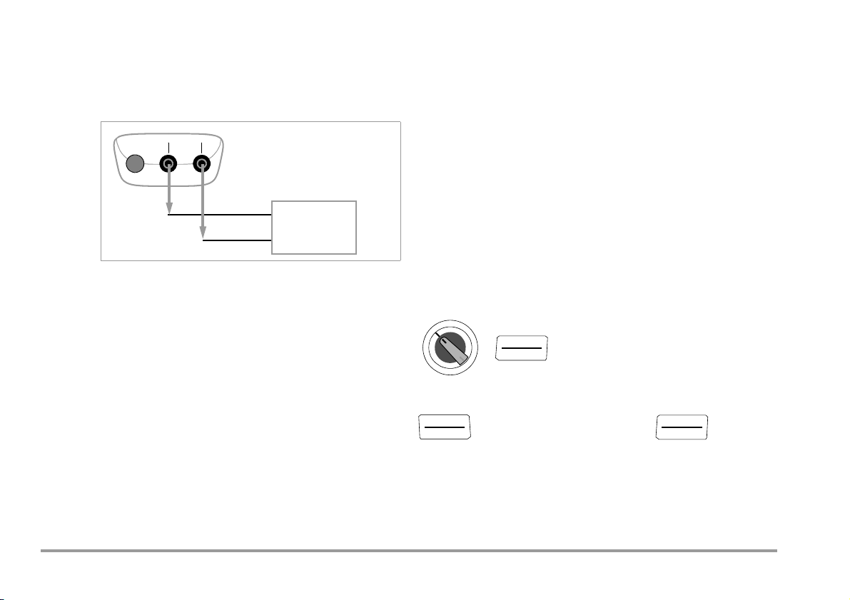
3 Voltage Source [V]
Output
CALIBRATOR
+
–
–
+
Input
Device to be calibrated, e.g.
measuring transducer
≥1kΩ
V
ON/OFF
LIGHT
ZERO/ SEL
ESC
OUT
ENTER
Voltages can be simulated within the following ranges:
0 … ±60 mV, 0 … ±300 mV, 0 … 3 V, 0 … 10 V and 0 … 15 V.
Resistance of the connected circuit should not be any less
than 1 kΩ.
Selecting a Voltage Range for the Fixed Value Function
➭ Press the ZERO/ SEL | ESC key in order to switch to the
[select range] menu.
➭ Select the desired voltage range with the keys.
Acknowledge your selection with OUT | ENTER.
The display is switched to the voltage value entry window, but
the selected voltage range still appears in the auxiliary display.
Selecting the Voltage Range for the Interval or Ramp Function
➭ Press the ZERO/ SEL | ESC key in order to switch to the
[
select range] menu. Select the desired voltage range with the
keys.
➭ Switch to the interval or ramp function menu with the
keys (see section 8). Start the respective function by pressing
OUT | ENTER.
➭ Connect the device to be calibrated with the measurement
cable as shown.
Abbreviated Instructions
Select calibration function.
➭ Select the V calibration function with the rotary switch.
➭ Switch the calibrator on by pressing the ON / OFF | LIGHT
key.
The last selected voltage range is displayed.
➭ Set the voltage value:
ON indicates:
Select voltage range and acknowledge for fixed value function.
Voltage is applied directly to the output!
Select the digit to be changed with the keys, and change
the respectively selected digit with the keys.
➭ The output can be deactivated with the OUT | ENTER key
[
out.off], or activated once again.
Change the fixed value.
000.00 V
(Negative values within a range of ±60 mV or ±300 mV can be selected by
scrolling with the
select range: 15 V … 60 mV
key to below the zero point.)
8 GMC-I Messtechnik GmbH
4 Frequency Generator (positive square-wave pulses) [Hz]
Note!
Attention!
!
ZERO/ SEL
ESC
ZERO/ SEL
ESC
OUT
ENTER
ZERO/ SEL
ESC
OUT
ENTER
Voltage and frequency can be set independent of each other for
frequency generators.
The output signal is a square wave. Resistance of the connected
circuit should not be any less than 1 kΩ.
➭ Connect the device to be calibrated with the measurement
cable in the same way as specified for the voltage simulator.
➭ Select the HZ calibration function with the rotary switch.
➭ Switch the calibrator on by pressing the ON / OFF | LIGHT
key.
➭ Set the voltage range (300 mV, 3 V, 10 V or 15 V):
Switch to the voltage range menu [
ZERO/SEL | ESC key twice. Select the desired voltage range
with the keys. Acknowledge your selection with
OUT | ENTER. The display is switched to the voltage
amplitude entry window.
➭ Set voltage amplitude (0 … 15 V):
Select the digit to be changed with the keys, and change
the respectively selected digit with the keys.
Acknowledge your selection with OUT | ENTER. The display is
switched to the frequency entry window, but the selected
voltage amplitude still appears in the auxiliary display.
➭ Set frequency (1 … 1000 Hz):
ON indicates: Voltage is applied directly to the output using the selected frequency!
Select the digit to be changed with the keys, and change
the respectively selected digit with the keys.
➭ The output can be deactivated with the OUT | ENTER key
[
out.off], or activated once again.
select range] by pressing the
The following error messages are possible:
“HiCurr” (high current – current at overload limit) where
I
=18mA, “0ut 0l” and 3 acoustic signals (out of
max.
limit – limit value exceeded) where I > 27 mA; the simulator
is switched off.
No interference voltage may be applied to the calibrator
jacks in this operating mode.
The calibrator is protected against brief application of a
large interference voltage with a replaceable fuse in the
event of operator error (see section 12.3).
Abbreviated Instructions
Set the voltage range (starting from frequency display).
select range: 15 V … 60 mV
Set voltage amplitude (starting from frequency display).
000.00 V
Set frequency.
0000.0 Hz
GMC-I Messtechnik GmbH 9
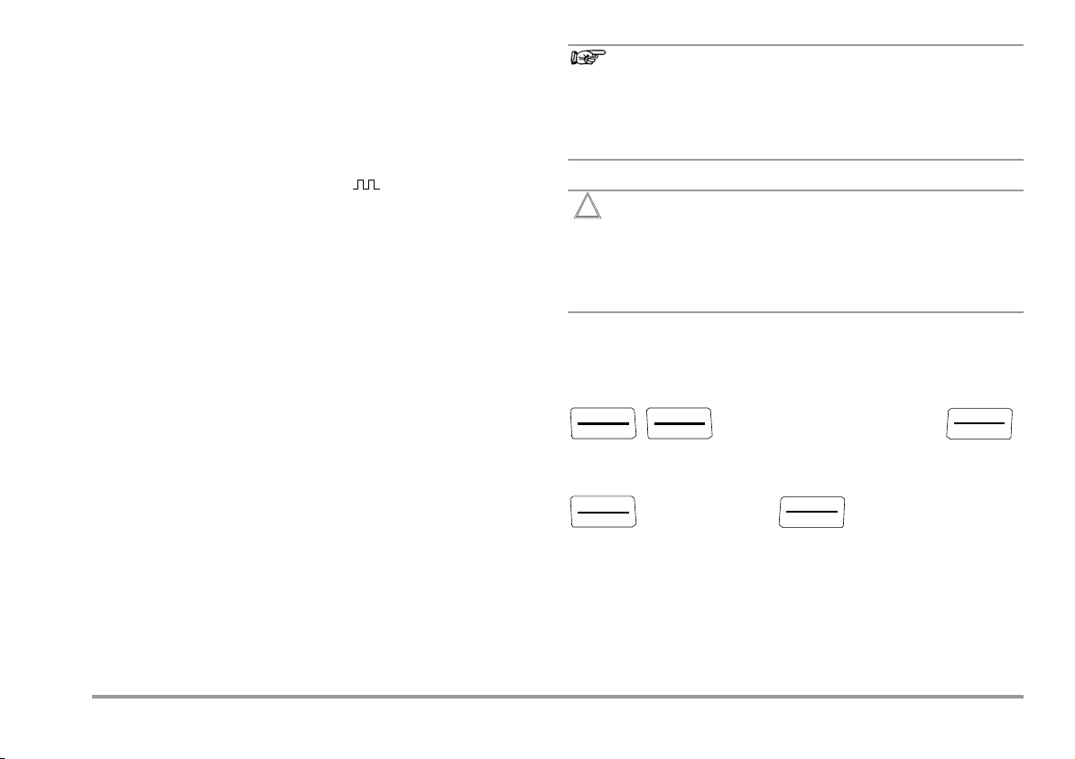
5 Resistance Simulation [Ω]
Note!
Attention!
!
Output
CALIBRATOR
+
–
2-Wire Resistance Simulation
Device to be Calibrated
–
+
Input
Measuring Current: 50 μA to 5 mA
Ω
ON/OFF
LIGHT
The resistance simulator is capable of simulating resistors using
Abbreviated Instructions
Select the calibration function.
2-wire connection for the following range: 5 … 2000 Ω.
Change the fixed value.
0000.0 Ω
The following error messages are possible:
“HiCurr” (high current – current value to high) where
I>4.5mA and
➭ Connect the device to be calibrated with the measurement
cable as shown.
“LoCurr” (low current – current too low or reversed polarity)
where I < 40 μA (corresponds to unconnected sockets)
➭ Select the Ω calibration function with the rotary switch.
➭ Switch the calibrator on by pressing the ON / OFF | LIGHT
key.
➭ Set the resistance simulation value:
ON indicates: The output is active!
Select the digit to be changed with the keys, and change
the respectively selected digit with the keys.
➭ The output can be deactivated with the OUT | ENTER key
[
out.off], or activated once again.
Switching Between the Fixed Value, Interval and Ramp Functions
➭ Press the ZERO/ SEL | ESC key in order to switch to the
[select range] menu.
➭ Switch to the interval or ramp function menu with the
keys. Start the respective function with OUT | ENTER.
No interference voltage may be applied to the calibrator
jacks in this operating mode.
The calibrator is protected against brief application of a
large interference voltage with a replaceable fuse in the
event of operator error (see section 12.3).
Response time of the calibrator output to the specified resistance
value after measuring current is applied is max. 30 ms. Devices
under test with non-continuous measuring current (e.g. scanned
measuring inputs) result in erroneous measured values if
measurement is started before response time has elapsed. The
calibrator cannot be used for devices of this type.
10 GMC-I Messtechnik GmbH
6 Temperature Simulation [°C / °F]
MEAS/ CAL
SETUP
OUT
ENTER
MEAS/ CAL
SETUP
OUT
ENTER
OUT
ENTER
OUT
ENTER
MEAS/ CAL
SETUP
MEAS/ CAL
SETUP
OUT
ENTER
OUT
ENTER
OUT
ENTER
OUT
ENTER
MEAS/ CAL
SETUP
MEAS/ CAL
SETUP
OUT
ENTER
OUT
ENTER
OUT
ENTER
OUT
ENTER
OUT
ENTER
MEAS/ CAL
SETUP
The temperature simulator is capable of simulating resistance
temperature detectors (RTD) or thermocouples (TC) with
specification of the external reference junction temperature.
➭ Connect the device to be calibrated with the measurement
cables.
➭ Select the Temp RTD or Temp TC calibration function with the
rotary switch.
➭ Switch the calibrator on by pressing the ON / OFF | LIGHT
key.
The last selected temperature sensor is displayed.
➭ Set the temperature value:
Simulated resistance or simulated voltage is applied directly to the
output!
Select the digit to be changed with the keys, and change
the respectively selected digit with the keys. As an
alternative, press and hold the keys with the cursor at
any entry position until the higher value digits are scrolled
through as well.
➭ The output can be deactivated with the OUT | ENTER key
[
out.off], or activated once again.
Query internal reference temperature – Info menu.
info
batt 2.9 V ... temp internal 23.7 °C
Parameter Entries for Thermocouple Temperature Simulation
Select unit of measure °C or °F – SEt menu.
info set
time ... temp internal
unit set °F °C
Select internal reference temperature – SEt menu.
info set
time ... temp external
unit set temp set external internal
temp internal 23.7 °C
Selecting Resistance Temperature Detector (RTD) or Thermocouple (TC)
for the Fixed Value, Interval or Ramp Function
➭ Switch to the fixed value, interval or ramp function menu by
pressing the ZERO/ SEL | ESC key.
➭ Select the [
select sensor] menu with the keys.
➭ Select the desired sensor with the keys. Acknowledge
your selection with OUT | ENTER. The display is switched to
the window for temperature value entry, but the selected
sensor still appears in the auxiliary display.
GMC-I Messtechnik GmbH 11
Select and set external reference temperature – SEt menu.
info set
time ... temp internal
unit set temp set internal external
external set 21.0 °C
temp external 22.4 °C

6.1 Temperature Simulation for Resistance Temperature Detectors –
RTD
ON/OFF
LIGHT
ZERO/ SEL
ESC
OUT
ENTER
TC
ON/OFF
LIGHT
ZERO/ SEL
ESC
OUT
ENTER
RTD setting for temperature
Resistance temperature detectors (types Pt100, Pt1000, Ni100
and Ni1000) are simulated by means of resistance values.
6.2 Temperature Simulation for Thermocouples – TC Temperature Setting
Thermocouples (types B, E, J, K, L, N, R, S, T and U) are
simulated with voltage. Internal or external temperature
compensation is possible.
Abbreviated Instructions
Select the calibration function.
Select a sensor value and acknowledge for the fixed value function.
select sensor Pt100 ... ni1000
Set the temperature simulator value.
120.0°C
Response time of the calibrator output to the specified resistance
value after measuring current is applied is max. 30 ms.
Devices under test with non-continuous measuring current (e.g.
scanned measuring inputs) result in erroneous measured values if
measurement is started before response time has elapsed. The
calibrator cannot be used for devices of this type.
Abbreviated Instructions
Select the calibration function.
Select a sensor type and acknowledge for the fixed value function.
select sensor b ... u
Set the temperature simulator value.
120.0 °C
Select internal or external reference temperature, set external reference
temperature (see page 11).
12 GMC-I Messtechnik GmbH

Function Description and Applications
Attention!
!
Output
CALIBRATOR
+
–
Output
CALIBRATOR
+
–
Device to be
Terminal Block
Equalizing Lead
Device to be
Copper Wire
Temperature measurement,
e.g. via multimeter with
temperature sensor
Example for point a),
internal reference junction
Example for point b),
external reference junction
Calibrated
Calibrated
10 different types of thermocouples can be selected, and can be
simulated within the temperature ranges specified by IEC/DIN.
Selection can be made between an internally measured reference
junction temperature, or numeric entry of an external reference
junction temperature within a range of –30 to +60 °C.
Important Notes Regarding Reference Temperature
Internal reference temperature is continuously measured with an
integrated temperature sensor. The reference temperature is
generally measured at the thermocouple connector jack for
devices to be calibrated with a thermocouple measurement input.
The two measurements may yield different results, and
differences are registered as errors during thermocouple
simulation. The following methods help to reduce this error:
a) The device to be calibrated is connected to the jacks at the
calibrator with equalizing leads for the thermocouple to be
simulated.
b) The temperature of the thermocouple connector jack at the
device to be calibrated is measured with a precision
temperature measuring instrument, and the resulting value is
entered to the calibrator as a reference temperature. The
calibrator and the device to be calibrated are connected with
copper wire.
No interference voltage may be applied to the calibrator
jacks in this operating mode.
The calibrator is protected against brief application of a
large interference voltage with a replaceable fuse in the
event of operator error (see section 12.3).
Otherwise, the external reference temperature is entered in all
cases where temperature measurement at the device to be
calibrated is accomplished by means of a thermostatic reference
junction (end of the thermocouple equalizing lead).
GMC-I Messtechnik GmbH 13

7 Current Source and Current Sink [mA]
mA
ON/OFF
LIGHT
ZERO/ SEL
ESC
OUT
ENTER
➭ Connect the device to be calibrated with the measurement
cables (see example in section 7.1).
➭ Select the mA current sink ( ) or mA current source ( )
calibration function with the rotary switch.
➭ Switch the calibrator on by pressing the ON / OFF | LIGHT
key.
The last selected current range is displayed.
➭ Set the current simulation value:
SINK ON indicates that the current sink is active! SOURCE ON
indicates that the current source is active!
Select the digit to be changed with the keys, and change
the respectively selected digit with the keys.
➭ The current sink / current source can be deactivated by
pressing the OUT | ENTER key [SINK/SOURCE
vated once again.
Selecting a Current Range for the Fixed Value Function
➭ Press the ZERO/ SEL | ESC key in order to switch to the
[
select range] menu.
➭ Select the desired current range with the keys
(0 … 20 mA, 4 … 20 mA or 0 … 24 mA).
Acknowledge your selection with OUT | ENTER.
The display is switched to the current value entry window, but
the selected current range still appears in the auxiliary display.
Selecting the Current Range for the Interval or Ramp Function
➭ Press ZERO/SEL | ESC key in order to switch to the
[
select range] menu. Select the desired current range with the
keys.
➭ Switch to the interval or ramp function menu with the
keys. Start the respective function with OUT | ENTER.
out.off], or acti-
Abbreviated Instructions
Select the calibration function.
Select a current range and acknowledge for the fixed value function.
select range 0 … 20 0 … 24 4 … 20
Change the fixed value.
15.00 mA
14 GMC-I Messtechnik GmbH

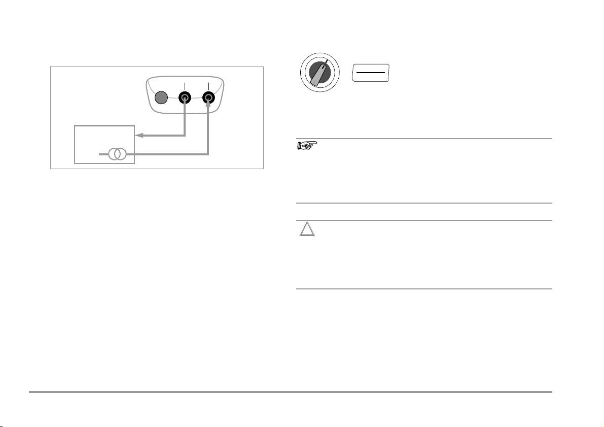
7.1 Current Sink – Simulation of a 2-Wire Transmitter
Output
CALIBRATOR
+
–
Peripheral Device
24 V
4 to 20 mA = 0 to 100 °C
+
+
–
Power
Supply
A current sink (0 … 24 mA) or current loop load can be simulated
with this function. The calibrator regulates the current, which flows
via the calibrator jacks from an external power supply
independent of direct voltage applied to the jacks (4 … 27 V). The
calibrator varies internal resistance such that the selected current
value is maintained.
Note!
The last selected simulation range is saved to memory.
Voltage at the calibrator jacks may not exceed 27 V in the
current sink operating mode, because thermal overload
would otherwise occur and the fuse would blow.
LoVolt appears at the display if voltage is too low.
Attention!
!
If the calibrator is used as a current sink and switched off
at closed electrical circuit or else switches off automatically due to low battery status, a high current may occur
which – depending on the capacity of the external voltage
source – trips the integrated fuse.
Do not switch off the calibrator before opening the electrical circuit.
Please make sure that the current sink function is only performed with sufficient battery capacity or in combination
with a power pack.
Example of a 2-Wire Transmitter Measuring Circuit
7.2 Current Source
Internal supply power is used to simulate a current source.
Note!
The current source’s internal control loop is monitored: If
voltage drop at the external load (burden) is greater than
16 V, or if the electrical circuit is interrupted, “Hi burd”
appears at the display.
Attention!
!
No interference voltage may be applied to the calibrator
jacks in this operating mode.
The calibrator is protected against brief application of a
large interference voltage with a replaceable fuse in the
event of operator error (see section 12.3).
CALIBRATOR
–
Output
Peripheral Device
+
–
+
GMC-I Messtechnik GmbH 15

8 Interval Functions, Ramp Functions and Procedures
Auto
Final Value
Initial Value
Initial Value
Final Value
Manual
Two types of setpoint sequences can be generated in order to
simulate sensor conditions at the inputs of transducers,
transmitters and buffer amplifiers:
• Interval sequences (see section 8.1)
Automatic (periodic) or manually controlled sequences
or
• Ramp sequences (see section 8.2)
Endless loops (periodic) or one-time only sequences
The above mentioned sequences can be conveniently generated
at a PC with the help of METRAwin90-2 software as an
accessory.
8.1 Interval Sequences – INT Function
Output ranges are divided into rising or falling interval steps with
this function, and the number of interval steps, as well as their
duration, can be specified. This function is above all suitable for
calibrating analog displays and recorders during one-man
operation.
Input parameters for interval sequences:
• All simulation functions except for Hz can be adjusted as
output quantities.
• A lower (Start) and an upper (
for each output quantity from within the overall range.
• The number of steps can be set within a range of 1 … 99.9.
The number of steps can be entered as a whole number as
well, which is especially practical for analog indicators and
recorders with non-standardized scale divisions.
• The interval duration per step (t1) can be selected from within
a range of 1 second to 60 minutes.
End) range limit can be selected
• Step jumps can be executed manually (
the and keys, or automatically (
1nt mode = Auto ) with
selectable time per step.
Examples of Automatic Interval Sequences
Examples of Manual Interval Sequences
1nt mode = manual) with
16 GMC-I Messtechnik GmbH

Setting the Interval Parameters
ZERO/ SEL
ESC
MEAS/ CAL
SETUP
OUT
ENTER
OUT
ENTER
OUT
ENTER
OUT
ENTER
OUT
ENTER
OUT
ENTER
4
8
12
16
20
t[s]
I
Source
manual stop
[mA]
➀➂
ESC
➁
Time intervals depend upon the operator (only
identical in automatic mode).
OUT
ENTER
ZERO/ SEL
ESC
seleCt range 300 mV … 15 V 1nt
Example of a Manually Controlled Interval Sequence
Initial value:
1nt start 02.000 V
Final value: 1nt end 10.000 V
Steps:
Dwell time:
Repetition:
(Auto = automatic sequence, MAnuAL = manual sequence)
1nt steps 03.0
1nt t1 00.05 min.s
1nt mode auto manual
Manually Controlled Interval Sequence
After entering all parameters for the “manual interval sequence”
output function (
1nt mode = manual ) and starting the function with
the key, the individual steps are triggered with the and
keys. The relationship between the output signal and each of
the key operations is depicted with the help of the following example.
GMC-I Messtechnik GmbH 17
Key
1 When 1nt
ready is displayed:
Start the sequence by pressing .
2 The sequence is continued in the corresponding direction by
pressing the or the key.
3 Stop the interval sequence by pressing .

Automatic Interval Sequence
2
4.6
7.3
10
t[s]
U
[V]
run up stop
➀➃➁
5101520250
➂
run dn hold run up run dn
HOLD CONT
LCD :
ESC/
OUT
ENTER
ZERO/ SEL
ESC
Example of an Automatic Interval Sequence
Automatic execution of a programmed sequence range is above
all advisable if feeding to a signal circuit and scanning of the
peripheral device under test are physically separated.
After entering all parameters for the “automatic interval sequence”
output function (see above) (I
nt, mode = auto), the sequence can be
started and stopped whenever desired, as well as resumed.
Interval parameters: output quantity: U (range of 0 … 15 V),
start =2V, end = 10 V, number of interval steps =3, t1 =5s,
mode = auto
Key
1 When 1nt
ready is displayed:
Start the sequence by pressing .
2 The sequence is stopped by pressing the or the key.
Interval time elapsed thus far is saved as t
18 GMC-I Messtechnik GmbH
3 The sequence is resumed by pressing the key; remaining
sequence duration ty=t1–tx.
4 Stop the interval sequence by pressing .
.
x

8.2 Read-Out a Periodic Ramp – RAMP Function
3, 0, 0 (t1, t2, t3)
1, 0, 4
0, 2, 0
0, 1, 2
0, 0, 3 (t1, t2, t3)
2, 0 ,2
2, 1 ,0
2, 1 ,2
Ramp-type signals can be used to test the dynamic performance
of devices to be calibrated, or entire measuring circuits. An
example would be performance of a control loop with a setpoint
specified via the analog setpoint input at the controller. The
instrument can be used to replace costly hardware and software
for the setup of long-term test bays with cyclical time sequences.
Parameters for the ramps depicted below:
• The following functions can be adjusted as output quantities:
• A lower (Start) and an upper (
• Rise time t1 and decay time t3 are adjustable from 0 seconds
• Dwell time t2 at the upper and lower range limits is adjustable
• There are 2 ramp sequences:
voltage U, current sink I sink, current source I source,
resistance R or temperature temp (TC or RTD).
End) range limit can be selected
for each output quantity from within the overall range.
to 60 minutes.
from 0 seconds to 60 minutes
– One-time only (
– Repetition (
onCE ): t1, t2, t3
repeat ): t1, t2, t3, t2, t1, t2, t3, …
Examples of Ramp Sequences
GMC-I Messtechnik GmbH 19

Setting Ramp Parameters
ZERO/ SEL
ESC
MEAS/ CAL
SETUP
OUT
ENTER
OUT
ENTER
OUT
ENTER
OUT
ENTER
OUT
ENTER
OUT
ENTER
Start
End
t1
t2
t3
t2
Output
t
OUT
ENTER
2 V
10 V
t1 t2 t3
LCD :
t3 t2
t1
➀➁➂➃➄➅
t1 up t2 run t3 dn t3 hld t3 up t3 run t3 hld t1 dn
U
[V]
HOLD CONT
HOLD CONT
/
/
ESC
OUT
ENTER
ZERO/ SEL
ESC
seleCt range 300 mV … 15 V ramp
Example of a Periodic Ramp Sequence Controlled by Manual Intervention
Initial value:
ramp start 02.000 V
Final value: ramp end 10.000 V
Rise time:
Dwell time:
Decay time:
ramp t1 00.05 min.s
ramp t2 00.08 min.s
ramp t3 00.05 min.s
Repetition: ramp mode repeat onCe
(rEPEAT = endless loop, onCE = one-time only)
Example of a Periodic Ramp Sequence
Manually Controlled Ramp Sequence
After entering all parameters, start by pressing .
Rising or decaying ramps can be triggered with the or key.
The relationship between the output signal and each of the key
operations is depicted with the help of the following example.
Ramp parameters: output quantity: U (range of 0 … 15 V),
start =2V, end =10V, t1 =5s, t2 =8s, t3 =5s, repeat for peri-
odic ramps
Key
1 When ramp ready is displayed:
Start the sequence by pressing .
2 Stop the decaying ramp within decay time t3 with the or
key.
3 Start a rising ramp within remaining decay time t3 with the
key.
4 Stop the ramp sequence by pressing the or key.
5 Start a decaying ramp with the key, remaining dwell time t2
is cleared.
6 Stop the ramp sequence by pressing .
20 GMC-I Messtechnik GmbH

9 Device and Calibration Parameters
MEAS/ CAL
SETUP
OUT
ENTER
OUT
ENTER
OUT
ENTER
OUT
ENTER
MEAS/ CAL
SETUP
OUT
ENTER
MEAS/ CAL
SETUP
OUT
ENTER
OUT
ENTER
OUT
ENTER
MEAS/ CAL
SETUP
The instrument’s “SET” mode (menu mode) makes it possible to
set operating and measuring parameters, query information and
activate the interface.
➭ The menu mode is accessed by pressing the MEAS/ CAL | SETUP
key, assuming that the instrument is switched on and set to
“Measure” (measuring mode operation).
“inFo” appears at the display.
➭ The main “SET” menu can be accessed, after which the display
can be returned to the “inFo” menu, by repeatedly pressing the
key (any direction).
➭ After selecting the desired main menu, sub-menus are
accessed by pressing the OUT | ENTER key.
➭ The desired parameter is selected by repeatedly pressing the
key.
➭ In order to check or change a parameter, acknowledge it with
the OUT | ENTER key.
➭ The
keys can be used to position the cursor at the entry
position.
The desired value is selected with the help of the
➭ Changes can only be accepted with the OUT | ENTER key.
➭ You can return to the sub-menu without making any changes
by pressing the ZERO/SEL | ESC key, and to the main menu by
pressing the ZERO/SEL | ESC key once again etc.
➭ You can switch to the calibrating mode from any menu level by
pressing the MEAS/CAL | SETUP key.
keys.
Example: Setting Time
inFo set t iME
t iME set 14:11 :11 (hh:mm:ss)
Setting hours and minutes:
Change the setting, the entry position blinks.
Advance to desired entry position.
Press and hold the key
to change the setting rapidly.
The new time setting is activated after
acknowledgement.
Querying Operating Parameters – SETUP Menu > Info
inFo bAtt ...
1tEMP internal
24.2° C
Parameters: see section 9.1.
Setting Operating Parameters – SETUP Menu > Set
info set
apoff unit set °F °C temp internal / external
time date addr irstb
temp set intern external external set 24.2° C
Parameters: see section 9.2.
GMC-I Messtechnik GmbH 21

9.1 Querying Parameters – InFo Menu
MEAS/ CAL
SETUP
OUT
ENTER
MEAS/ CAL
SETUP
OUT
ENTER
MEAS/ CAL
SETUP
OUT
ENTER
MEAS/ CAL
SETUP
OUT
ENTER
MEAS/ CAL
SETUP
OUT
ENTER
OUT
ENTER
OUT
ENTER
MEAS/ CAL
SETUP
OUT
ENTER
OUT
ENTER
OUT
ENTER
OUT
ENTER
9.2 Entering Parameters – SETUP Menu
bAtt – query battery voltage
inFo
bAtt 3.1 V.
tiME / dAtE – query date and time
bAtt
inFo
DD.MM.YYYY hh:mm:ss
D = day, M = month, Y = year, h = hour, m = minute, s = second
... 02.01.
2008 13:46:56
Date and time must be reentered after replacing the batteries.
cALdAt – query calibration date
inFo
caldat 02.01.08 uEr 0.
.
04
bAtt
...
ItEMP – query internal reference temperature and temperature unit of
measure
The temperature of the internal reference junction is measured
with a temperature sensor in close proximity to the input sockets.
bAtt
...
inFo
1tEMP internal
24.2° C
tiME – set time
Entering the correct time makes it possible to calibrate in
real-time.
inFo SET time
time set 10:24:24 (hh:mm:ss)
Date and time must be reentered after replacing the batteries.
dAtE – enter date
Entering the current date makes it possible to calibrate in
real-time.
SET time dAtE
inFo
date set 02.01 (DD: day . MM: month) wrs
year set 2008 (YYYY: year)
Date and time must be reentered after replacing the batteries.
22 GMC-I Messtechnik GmbH

Addr – set device address
MEAS/ CAL
SETUP
OUT
ENTER
OUT
ENTER
ZERO/ SEL
ESC
ON / OFF
LIGHT
tEMP – °C / °F setting, select internal/external reference temperature
See section 10.2 regarding settings.
irStb – status of the infrared receiver in the stand-by mode
See section 10.2 regarding settings.
APoFF – specified time for automatic shutdown and continuous ON
The instrument is switched off automatically if the calibration value
remains unchanged for a long period of time and if none of the
keys or the rotary switch have been activated before the specified
time “APoFF” (entered in minutes) has elapsed.
If a value between 10 and 59 minutes is set, this value is retained
even after switching the instrument off.
Operating mode "Continuously ON"
If you select setting on, the calibrator is set to continuous operation. is shown on the bottom left of the display. Alternatively,
you can set operating mode "Continuoulsy ON" with the instrument keys (prerequisite: switch position other than OFF and
instrument OFF):
Press and hold the two keys OUT | ENTER and ON / OFF | LIGHT until
the display test is activated.
The calibrator can now be switched off manually only. After
switching it on again, a default value of 10 minutes is preset.
... SET time ... APoFF
inFo
See section 6 regarding selection.
9.3 Default Settings
Previously entered changes can be undone, and the default
settings can be reactivated. This may be advisable under the
following circumstances:
• After the occurrence of software or hardware errors
• If you are under the impression that the multimeter does not
work correctly
➭ Disconnect the device from the circuit.
➭ Remove the batteries temporarily (see also section 12.2).
➭ Simultaneously press and hold the and
keys, and connect the batteries at the same time.
APoFF
set 10 ... 59 min on
(10 minutes = default setting)
GMC-I Messtechnik GmbH 23

10 Interface Operation (with selector switch setting ≠ OFF)
MEAS/ CAL
SETUP
OUT
ENTER
OUT
ENTER
OUT
ENTER
MEAS/ CAL
SETUP
OUT
ENTER
OUT
ENTER
OUT
ENTER
The calibrator is equipped with an infrared interface for communication with the PC. Commands are optically transferred through
the instrument housing by means of infrared light to an
interface adapter (accessory) which is attached to the calibrator.
The adapter’s USB interface allows for connection to the PC with
an interface cable.
Commands and parameters can be transmitted from the PC to
the calibrator. The following functions can be executed:
• Configuration and read-out of calibration parameters
• Calibration function and measuring range selection
• Start calibration
• Programming of user-specific procedures (interval and ramp
functions)
10.1 Activating the Interface
The interface is automatically activated for receiving operation
(calibrator receives data from the PC) as soon as the interface is
addressed by the PC, assuming that the “
been set to “on” (see section 10.2), or the instrument is already
switched on (the first command wakes up the calibrator, but does
not yet execute any further commands).
Switching the Interface On via the PC
After transmission of a data frame from the PC, the simulator is
switched on. Use the power pack for lengthy on-times for this
reason. This prevents automatic shutdown due to battery voltage
monitoring.
Operation in the REMOTE Mode
In the REMOTE mode, the device responds just like it does in the
local mode. The device is reset to local mode operation after
switching it off and back on again with the ON / OFF | LIGHT key.
1rStb” parameter has
10.2 Configuring Interface Parameters 1rStb – status of the infrared receiver in the stand-by mode
There are two possible switching statuses for the infrared
interface when the calibrator is switched off:
on: IR appears at the display and the infrared interface is
active, i.e. signals such as making commands can be
received, and power is consumed even though the
calibrator is switched off.
oFF: IR does not appear at the display and the infrared
interface is switched off; signals cannot be received.
inFo
... SET time ... irStb
irStb Set on / oFF
(irstb = oFF = default setting)
Addr – address
If several calibrators are connected to the PC via an interface
adapter, a separate address can be assigned to each instrument.
Address number 1 should be selected for the first instrument, 2
should be assigned to the second and so forth.
inFo
... SET time ... Addr
00 ... 01 ... 15
(Addr = 15 = default setting)
24 GMC-I Messtechnik GmbH

11 Technical Data
Note!
Simulation
Range
Calibration
Function
Direct Voltage Source Minimum Load
0…±300 mV 0.01 mV
0 … 3 V 0.1 mV 0.05 + 0.2
V
0 … 10 V 1 mV 0.05 + 2
0 … 15 V 1 mV 0.05 + 2
Frequency Generator
Duty cycle (pulse-no-pulse ratio): 50%,
amplitude: 10 mV … 15 V
Hz
1 Hz … 1 kHz
Current Source Max. load ±(% S + μA)
4 … 20 mA
mA
0 … 24 mA
Current Sink ±(% S + μA) U
4 … 20 mA
mA
0 … 24 mA
Resistance Simulation
Ω 5 … 2000 Ω 0.1 Ω 0.05...0.1..4...5 0.05 + 0.2 5 mA
Observe maximum allowable voltage for connection from external
sources to the calibrator output if current sink is selected: U
27 V. The calibrator is protected against brief application of a large
interference voltage with a replaceable fuse in the event of
operator error., i.e. in case of overloading (> I
may blow.
Resolution,
30,000
Digits
(4¾ places)
Resistance
1 kΩ
Minimum Load
Resistance ±(% S + Hz) I
0.1 … 1 Hz 1 kΩ 0.05 + 0.2 18 mA
1 μA 16 V 0.05 + 20 … 20 mA
1 μAVin = 4 ... 27 V 0.05 + 2 27 V0 … 20 mA
Sensor current [mA]
Intrinsic
Uncertainty
±(% S + mV) I
0.05 + 0.02
±(% S + Ω)I
Overload
18 mA
max/Umax
max
max
max
max
) the fuse
ext
Simulator for Temperature Sensors (resolution: 0.1 K)
Sensor Type Simulation
Resistance Thermometer per IEC 751 ±(% S + K) I
Pt100 – 200 …+ 850 –328…+ 1562 0.1 + 0.5
Pt1000 –200 …+300 –328 …+572 0.1 + 0.2
Resistance Thermometer per DIN 43760 ±(% S + K) I
Ni100 –60 …+ 180 –76 …+356 0.1 + 0.5
Ni1000 –60 …+180 –76 …+ 356 0.1 + 0.2
RTD sensor current: 0.05 ... 0.1 ... 4
Thermocouples per DIN and IEC 584-1
K (NiCr/Ni)
°C / °F
J (Fe/CuNi)
T (Cu/CuNi) –270…+ 400 – 454…+752
B (Pt30Rh/Pt6Rh) +500...+1820 +932…+3308
E (NiCr/CuNi)
R (Pt13Rh/Pt) –50…+1768 –58…+3214
N (NiCrSi-NiSi)
S (Pt10Rh/Pt) –50…+1768 –58…+3214
L (Fe/CuNi) –200…+ 900 – 328…+1652
U (Cu/CuNi) –200…+ 600 –328…+ 1112
Range
in °C
–250…+1372
–210…+1200
–270…+1000
–270…+1300
* Without internal reference junction;
relative to fixed external reference temperature
and thermovoltage of the thermocouple,
0 to
Regarding additional error see also the table on page 26.
Internal reference junction: 2 K intrinsic error
External reference junction: entry of –30 to 60 °C
Simulation
Range
in °F
... 5 mA
–418…+2501
–346…+2192
–454…+1832
–454…+2372
Key
S = setting value
Intrinsic
Uncertainty
*
Δ
U in mV * I
±
( 0.05%
of |Setting|
+
0.02 mV )
Overload
5 mA
5 mA
18 mA
max
max
max
GMC-I Messtechnik GmbH 25

Internal clock
Time format DD.MM.YYYY hh:mm:ss
Resolution 0.1 s
Accuracy ±1 minute per month
Temperature Influence 50 ppm / K
Reference Conditions
Ambient temperature +23 °C ±2K
Relative humidity 40 ... 75%
Battery voltage 3.0 V ±10 %
Thermocouple Simulation Error [°C]
Thermocouple error is specified in the technical data as
thermovoltage error: ΔU. ΔT error is dependent upon
characteristic thermocouple slope.
In consideration of characteristic thermocouple non-linearity,
which also applies to slope (1
st
dT/dU derivation) mathematically
calculated ΔT error is shown in the following table for all
thermocouple types in the 100 °C sub-range. The values shown
in the table represent maximum possible error for the respective
sub-range.
If an internal reference temperature is used, the intrinsic error of
the reference junction must be taken into account .
If an external reference temperature of other than 0 °C is used, the
sub-ranges of the table on the right apply, adjusted by the
amount of the relevant reference temperature.
Example
External reference temperature = 50 °C: the errors of the subrange 100 … 200 °C apply for setting values from 50 … 150 °C.
Additional Error for Thermocouple Simulation
Thermocouple Type T Error in K for Thermocouple Types (ref. temp. 0° C)
Sub-Range: °CJLTUKESRBN
– 200 ... –100
– 100 ... 0
0 ... 100
100 ... 200
200 ... 300
300 ... 400
400 ... 500
500 ... 600
600 ... 700
700 ... 800
800 ... 900
900 ... 1000
1000 ... 1100
1100 ... 1200
1200 ... 1300
1300 ... 1400
1400 ... 1500
1500 ... 1600
1600 ... 1700
1700 ... 1800
1.2 1.0 1.6 1.4 1.6 1.1 2.3
*)
0.6 0.8 0.9 0.9 0.8 0.6
0.5 0.6 0.6 0.6 0.7 0.5 3.8 3.9 0.9
0.6 0.7 0.6 0.6 0.7 0.5 3.2 3.2 0.8
0.6 0.7 0.6 0.6 0.7 0.5 2.6 2.5 0.8
0.7 0.8 0.6 0.6 0.8 0.5 2.5 2.3 0.8
0.7 0.8 0.6 0.8 0.6 2.4 2.2 0.9
0.7 0.9 0.6 0.9 0.6 2.4 2.2 4.2 0.9
0.8 0.9 0.9 0.7 2.3 2.1 3.6 0.9
0.8 0.9 1.0 0.8 2.3 2.1 3.3 1.0
0.9 0.9 1.1 0.8 2.3 2.1 2.9 1.0
0.9 1.2 0.9 2.3 2.0 2.8 1.1
1.0 1.2 2.3 2.0 2.6 1.2
1.1 1.3 2.3 2.0 2.5 1.3
1.4 2.3 2.1 2.4 1.4
1.5 2.4 2.1 2.3
*)
5.2
5.5
2.4 2.2 2.3
2.5 2.2 2.3
2.6 2.3 2.3
2.8 2.5 2.4
1.1
Temperature conversion from centigrades to Fahrenheit:
T [°F] = 32 + T [°C] x 1.8.
26 GMC-I Messtechnik GmbH

Display
LCD panel (65 mm x 36 mm) with digital display including simulation unit of measure and various special functions
Background Illumination
Background illumination is switched off approximately 1 minute after it has
been activated.
Display / Char. Height 7-segment characters
Max. Resolution 30 000
Polarity Display “–” (minus sign) is displayed
Refresh Rate 2 times per second, every 500 ms
Main display: 1 x 6 digits, 12 mm
Auxiliary displays: 2 x 6 digits, 7 mm
Power Supply
Battery 2 AA size batteries
Service life With alkaline manganese (2600 mAh)
Battery Indicator Battery capacity display with battery symbol in 4
Alkaline manganese per IEC LR6
(2 ea. 1.2 V NiMH rechargeable battery also
possible)
Calibration Function power
consumption
mV, thermocouple 55 mA 45 h
15 V 240 mA 10 h
Ω, RTD 85 mA 30 h
Sink, 20 mA 310 mA 8 h
Source, 20 mA 310 mA 8 h
If voltage drops below 1.8 V, the instrument is
switched off automatically.
segments: “ ”
Querying of momentary battery voltage via
menu function.
Service life
Power Saving Circuit
The device is shut down automatically if none of its controls are
activated during the specified “AP oFF” time. The simulator is
switched off after a period of only 5 minutes (sockets are current
and voltage-free). Automatic shutdown can be deactivated.
Power pack socket
If the NA X-TRA power pack is plugged in,
the installed batteries are disconnected
automatically.
Rechargeable batteries can only be recharged
externally.
Fuses
Refer to section 12.3 regarding location of the fuse link.
FF160mA/400V, 5 mm x 20 mm
min. 10 kA breaking capacity
(Article number: Z109N)
Electrical Safety
Protection class II per EN 61010-1:2010/VDE 0411-1:2011
Operating voltage Max. 50 V
Measuring category I (250 V)
Pollution degree 2
Test voltage 500 V~ per EN 61010-1:2010/VDE 0411-
1:2011
Electromagnetic Compatibility (EMC)
Interference emission
Interference immunity
EN 61326-1:2006, class B
EN 61326-1:2006
EN 61326-2-1:2006
GMC-I Messtechnik GmbH 27

Data Interface
Type
Data transmission Serial, bidirectional (not IrDa compatible)
Protocol Device specific
Baud rate 38,400 baud
Functions Set/query calibration functions and parameters.
Optical via infrared light through the housing
The USB X-
TRA plug-in interface adapter (see
accessories) is used for adaptation to the PC’s
USB port.
Ambient Conditions
Accuracy range 0 °C ... +40 °C
Operating temp. range −10 °C ... + 50 °C
Storage temp. range −25 °C ... +70 °C (without batteries)
Relative humidity 40% ... 75 %,
no condensation allowed
Elevation To 2000 m
Mechanical Design
Housing Impact resistant plastic (ABS)
Dimensions 200 x 87 x 45 mm
Weight Approx. 0.35 kg with batteries
Protection IP 54
Table Excerpt Regarding Significance of IP Codes
st
(1
IP XY
char. X)
Protection against penetration by solid particles
5 Dust protected 4 Splashing water
(without protective rubber cover)
(pressure equalization via the housing)
IP XY
(2nd char. Y)
Protection against
penetration by water
28 GMC-I Messtechnik GmbH

12 Maintenance
Attention!
!
Note!
Note!
MEAS/ CAL
SETUP
OUT
ENTER
Disconnect the instrument from the device to be
calibrated before opening to replace batteries or fuses!
12.1 Displays – Error Messages
Message Meaning
FUSE
12.2 Batteries
Blown fuse
Battery voltage has fallen below 1.8 V
Removing the Batteries During Periods of Non-Use
The integrated quartz movement draws power from the
batteries even when the instrument is switched off. It is
advisable to remove the batteries during long periods of
non-use for this reason (e.g. vacation). This prevents
excessive depletion of the battery, which may result in
damage under unfavorable conditions.
Battery Replacement
The selected operating parameters remain in memory,
although date and time must be reentered.
Charge Level
The current battery charge level can be queried in the “1nfo”
menu:
info bAtt 2.7 V
Make sure that no battery leakage has occurred before initial
start-up, as well as after long periods of storage. Continue to
inspect the batteries for leakage at short, regular intervals.
If battery leakage has occurred, carefully and completely clean the
electrolyte from the instrument with a damp cloth, and replace the
battery before using the instrument.
If the “ ” symbol appears at the display, the batteries should
be replaced as soon as possible. You can continue working with
the instrument, but reduced accuracy may result.
The instrument requires two 1.5 V batteries in accordance with
IEC R 6 or IEC LR 6, or two equivalent rechargeable NiCd
batteries.
GMC-I Messtechnik GmbH 29

Replacing the Batteries
Attention!
!
Attention!
!
Attention!
!
Blown Fuse
fuse
A
DC
Disconnect the instrument from the device to be
calibrated before opening the battery compartment lid
when replacing the batteries.
➭ Set the instrument face down onto the working surface.
➭ Turn the slotted screw on the lid with the battery symbols
counterclockwise.
➭ Lift off the lid and remove the batteries from the battery
compartment.
➭ Insert two new 1.5 V mignon batteries into the battery
compartment, making sure that the plus and minus poles
match up with the provided polarity symbols.
➭ When replacing the battery compartment lid, insert the side
with the guide hooks first. Tighten the screw by turning it
clockwise.
➭ Please dispose of depleted batteries in accordance with
environmental protection regulations!
12.3 Fuses
Testing the Fuse
The fuse is tested automatically when the device is switched on.
If the fuse is blown or has not been inserted, “FuSE” blinks at the
digital display. The same message appears if the output sockets
are short circuited when the device is switched on.
Replacing the Fuse
If a fuse should blow, eliminate the cause of overload before
placing the instrument back into service!
Disconnect the instrument from the device to be
calibrated before opening the fuse cover in order to
replace the fuse!
➭ Set the instrument face down onto the working surface.
➭ Turn the slotted screw on the cover with the fuse symbol
counterclockwise.
➭ Lift off the cover and pry the fuse out using the flat side of the
fuse cover.
➭ Insert a new fuse. Make sure that the fuse is centered, i.e.
located between the tabs at the sides.
➭ When replacing the fuse cover, insert the side with the guide
hooks first. Tighten the screw by turning it clockwise.
➭ Dispose of the blown fuse with the trash.
Use specified fuses only!
If fuses with other blowing characteristics, other current
ratings or other breaking capacities are used, the operator
is placed in danger, and protective diodes, resistors and
other components may be damaged.
The use of repaired fuses or short-circuiting the fuse
holder is prohibited.
30 GMC-I Messtechnik GmbH

Note!
Testing the Fuse with the Instrument Switched On
After inserting the fuse with the instrument switched on, it must
be switched off briefly and then switched back on again. If contact is poor or the fuse is blown, FUSE blinks at the display.
12.4 Housing Maintenance
No special maintenance is required for the housing. Keep outside
surfaces clean. Use a slightly dampened cloth for cleaning. Avoid
the use of cleansers, abrasives or solvents.
12.5 Return and Environmentally Sound Disposal
This calibrator is a category 9 product (monitoring and
control instrument) in accordance with ElektroG (German
electrical and electronic device law). This device is subject to the
RoHS directive. Further-more, we make reference to the fact that
the current status in this regard can be accessed on the Internet
at www.gossenmetrawatt.com by entering the search term
WEEE.
We identify our electrical and electronic devices in accordance with WEEE 2012/19/EU and ElektroG using the
symbol shown at the right per DIN EN 50419.
These devices may not be disposed of with the trash. Please
contact our service department regarding the return of old
devices (see section 15).
If you use
batteries
or
rechargeable batteries
in your instrument or
accessories which no longer function properly, they must be duly disposed of in compliance with the applicable national regulations.
Batteries or rechargeable batteries may contain harmful substances
or heavy metal such as lead (PB), cadmium (CD) or mercury (Hg).
They symbol shown to the right indicates that batteries or
rechargeable batteries may not be disposed of with the
trash, but must be delivered to collection points specially
provided for this purpose.
Pb Cd Hg
13 Calibrator Messages
The following messages appear at the main or the auxiliary
displays as required. See page 3 for messages displayed at
visible segments.
Message Function Meaning
Simulation of
hiCurr
loCurr
lovolt
hiBurd
voltage/pulse
Simulation of
resistance/RTD
Resistance
simulator
Voltage simulator,
frequency
generator
0ut0l
Current sink U < 3 V (to little loop voltage)
Current source High burden:
Blinking Calibration Unit of Measure
All calibration functions are balanced/adjusted in accordance with
the respective technical specifications at the factory. If a calibration unit of measure blinks, this indicates that balancing constants
which have been
established and saved to the calibrator are no longer available for
the respective function. If this is the case, results may deviate
from the specification. We recommend sending the instrument to
our Repair and Replacement Parts department for rebalancing
(see section 15).
High current = current too high (I > 18 mA)
High current = current too high (I > 4.5 mA)
Low current = current too low (I < 40 μA)
( indicates that connector jacks are open)
or reversed polarity, e.g. with Pt and Ni sensors
Output overload = limit value violated (I > 30 mA),
3 acoustic signals are generated at the same time
and the simulator jacks are deactivated. After eliminating the cause of overload, the output can once
again be switched on by pressing the ON / OFF |
LIGHT key.
Resistance applied by means of the connected circuit is too high. Voltage built up at the
calibrator is equal to or greater than
16 V.
GMC-I Messtechnik GmbH 31

14 Accessories
Attention!
!
14.1 General
The extensive accessories available for our measuring instruments and calibrators are checked for compliance with currently
valid safety regulations at regular intervals, and are expanded as
required for new applications. Currently up-to-date accessories
which are suitable for your measuring instrument are listed at the
following web address along with photo, order number, description and, depending upon the scope of the respective accessory,
data sheet and operating instructions: www.gossenmetrawatt.de
(→ Products → Measuring Technology – Portable →
Calibrators → METRAHIT CAL → Accessories).
14.2 Power Pack NA X-TRA (not included)
Use only power packs from GMC-I Messtechnik GmbH only in
combination with your instrument. This assures operator safety by
means of an extremely well insulated cable, and safe electrical
isolation (nominal secondary ratings: 5 V / 600 mA).
Installed batteries are disconnected electronically if the power
pack is used, and need not be removed from the instrument.
14.3 Technical Data for Measurement Cables (scope of delivery: KS17 safety cable set)
Electrical Safety
Maximum Rated Voltage 600 V
Measuring Category
CAT IV CAT III CAT II
1000 V
1000 V
Maximum Rated Current 1 A 1 A 16 A
with safety cap applied
without safety cap applied —
••—
—
Ambient Conditions (EN 61010-031)
Tem pe ra tu re –2 0 °C ... + 50 °C
Relative humidity 50 to 80%
Contamination level
2
Application KS17
Please observe the maximum values of the electrical safety of
the device.
In conformity with standard DIN EN 61010-031, measurements in an environment according to measuring category
III may only be performed with the safety cap applied to
the test probe of the measurement cable.
•
For establishing contact in 4 mm jacks you have to remove the
safety cap by levering out the snap lock of the safety cap with another sharp object (e.g. the second test probe).
32 GMC-I Messtechnik GmbH

14.4 USB X-TRA Bidirectional Interface Adapter
This adapter makes it possible to connect the calibrator to a USB
port at a PC. The adapter allows for data transmission between
the calibrator and the PC.
14.5 METRAwin 90 Software METRAwin 90 calibration software is a multilingual program* for
controlling various calibrators for electrical quantities with the help
of a PC, and for documenting calibration results.
Please refer to the METRAwin 90 installation instructions for a
description of the METRAwin 90-2, METRAwin 90-F and
METRAwin 90-FJ product variants and their detailed system
requirements.
* runs under an IBM compatible Windows operating system
GMC-I Messtechnik GmbH 33

15 Repair and Replacement Parts Service
Calibration Center * and Rental Instrument Service
If required please contact:
GMC-I Service GmbH
Service Center
Thomas-Mann-Str. 20
90471 Nuremberg, Germany
Phone: +49 911 817718-0
Fax: +49 911 817718-253
E-mail service@gossenmetrawatt.com
www.gmci-service.com
This address is only valid in Germany.
Please contact our representatives or subsidiaries for
service in other countries.
* DAkkS Calibration Laboratory for Measured Electrical Quantities
D-K-15080-01-01 accredited per DIN EN ISO/IEC 17025:2005
Accredited quantities: direct voltage, direct current value, direct current resistance,
alternating voltage, alternating current value, AC active power, AC apparent power,
DC power, capacitance, frequency and temperature
Competent Partner
GMC-I Messtechnik GmbH is certified in accordance with
DIN EN ISO 9001:2008.
Our DAkkS calibration laboratory is accredited by the Deutsche
Akkreditierungsstelle GmbH (National accreditation body for the
Republic of Germany) in accordance with DIN EN ISO/
IEC 17025:2005 under registration number D-K-15080-01-01.
We offer a complete range of expertise in the field of metrology:
from test reports and factory calibration certificates, right on up to
DAkkS calibration certificates.
Our spectrum of offerings is rounded out with free test equipment
management.
Our service department includes an on-site DAkkS calibration bench.
If errors are discovered during calibration, our specialized personnel are capable of completing repairs using original replacement
parts.
As a full service calibration lab, we can calibrate instruments from
other manufacturers as well.
Services
• Pick-up and delivery
• Express service (immediate, 24 hour and weekend service)
• Initial start-up and queries
• Device and software updates to current standards
• Replacement parts and repairs
• Help desk
• DAkkS calibration lab per DIN EN ISO/IEC 17025:2005
• Service contracts and test equipment management
• Rental instrument service
• Disposal of old instruments
DAkkS Calibration Certificate Reprints
If you order a DAkkS calibration certificate reprint for your
instrument, please provide us with the reference numbers
indicated in the upper and lower most fields of the calibration seal.
We do not need the instrument’s serial number.
34 GMC-I Messtechnik GmbH

16 Guarantee
All METRA HIT digital multimeters and calibration instruments are
guaranteed for a period of 3 years after shipment. The manufacturer’s guarantee covers materials and workmanship. Damages
resulting from use for any other than the intended purpose or
operating errors, as well as any and all consequential damages,
are excluded.
The calibration certificate confirms that the product conformed to
the specified technical data at the time of calibration. We guarantee the observance of the specified technical data within the
admissible tolerance limits for a period of 12 months from delivery.
18 Recalibration
The respective measuring task and the stress to which your calibrator is subjected affect the ageing of the components and may
result in deviations from the guaranteed accuracy.
If high measuring accuracy is required and the instrument is frequently used in field applications, combined with transport stress
and great temperature fluctuations, we recommend a relatively
short calibration interval of 1 year. If your calibrator is mainly used
in the laboratory and indoors without being exposed to any major
climatic or mechanical stress, a calibration interval of 2-3 years is
usually sufficient.
17 Product Support
If required please contact:
(DIN EN ISO/IEC 17025) the deviations of your instrument in relation to traceable standards are measured and documented. The
deviations determined in the process are used for correction of
During recalibration* in an accredited calibration laboratory
GMC-I Messtechnik GmbH
Product Support Hotline
Phone: +49 911 8602-0
Fax +49 911 8602-709
E-Mail: support@gossenmetrawatt.com
the readings during subsequent application.
We are pleased to perform DAkkS or factory calibrations for you in
our calibration laboratory. Please visit our website at
www.gossenmetrawatt.com (→ Company → DAkkS Calibration
Center or → FAQs → Calibration questions and answers).
By having your calibrator calibrated regularly, you fulfill the requirements of a quality management system per DIN EN ISO 9001.
* Verification of specifications or adjustment services are not part of the
calibration. For products from our factory, however, any necessary adjustment is frequently performed and the observance of the relevant
specification is confirmed.
GMC-I Messtechnik GmbH 35

Phone: +49-911 8602-111
Fax: +49 911 8602-777
E-Mail: info@gossenmetrawatt.com
www.gossenmetrawatt.com
GMC-I Messtechnik GmbH
Südwestpark 15
90449 Nürnberg •
Germany
Prepared in Germany • Subject to change without notice • PDF version available from the Internet
 Loading...