

Page 1
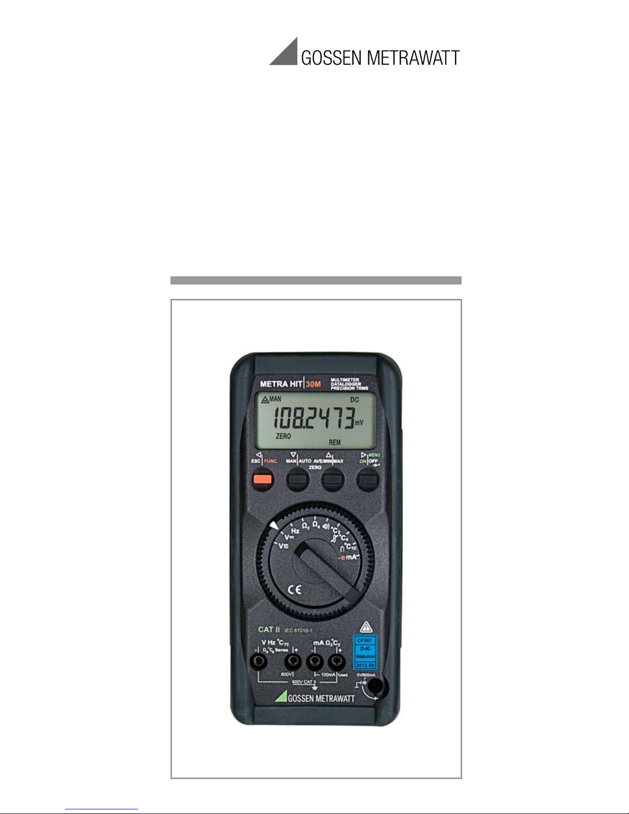
METRAHIT⏐30M
Precision Digital Multimeter
3-348-978-02
9/3.15
Operating Instructions
Page 2
2 GMC-I Messtechnik GmbH
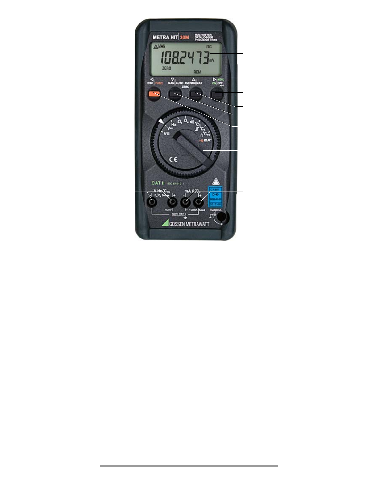
1 LCD display, see page 3 for description
2 MENU/ON| OFF key
Menu Operating Mode: Entry acknowledgment (ENTER or ↵)
3 AVE/MIN|MAX key for storage of MIN or MAX values, as well
as for displaying time since beginning of recording
Menu Operating Mode: selection of individual parameters,
reverse flux direction,
increase values
4 MAN|AUTO key for manual measuring range selection
Menu Operating Mode: selection of individual parameters,
forward flux direction,
reduce values
5 ESC| FUNC multifunction key
Menu Operating Mode: Exit menu level and
return to next highest level,
exit parameter entry mode
without storage of values
6 Rotary switch for measurement functions
7 Connector jacks
8 Power pack connection jack NA HIT 2X
1
2
3
4
5
6
7
7
8
Page 3
GMC-I Messtechnik GmbH 3
GB
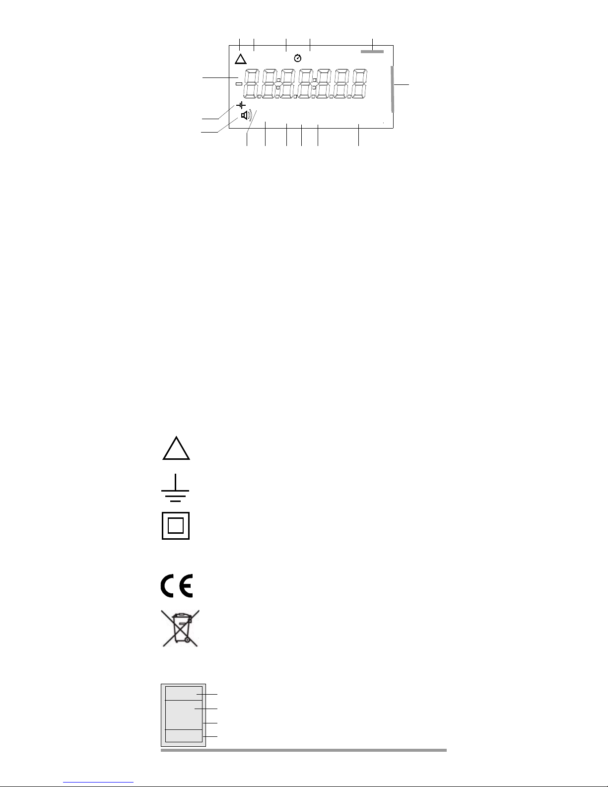
Digital Display Symbols
1 Digital display with decimal place and polarity
2 Continuous operation
3 Manual measuring range selection
4 MIN value storage
5 MAX value storage
6 Selected current and voltage type
7 Unit of measure
8 Filter active
9 Message: measurement value memory is full
10 Percentage memory full
11 Memory mode active
12 Menu operating mode active
13 Zero balancing
14 Continuity testing activated
15 Low battery
Meaning of symbols on the instrument
Warning concerning a point of danger
(Attention: observe documentation)
Ground
Continuous, doubled or reinforced insulation
CAT II Measuring category II instrument 600 V
Indicates EU conformity
This device may not be disposed with the
trash. For further details on the WEEE marking, please refer to our website www.gossenmetrawatt.com and enter search key ’WEEE’.
Calibration mark (blue seal):
23 6
7
891112
14
15
4
mV
FILTFULL REM%MEM
ZERO
MENU
o
F
A
I
uF
I
Hz
k
Ω
u
M
Ω
nF
C
o
k
AVE
ON
ON
MANDATA MIN MAX tEVENTS
DC
AC
5
1013
1
!
Serial number
Registration number
Date of calibraion (year – month)
German Accrediation Body GmbH – Calibration lab
XY123
2012-10
D-K-
15080-01-01
Page 4

4 GMC-I Messtechnik GmbH
Table of Contents
Page
1 Safety Features and Precautions .................................... 5
2 Initial Start-Up ................................................................. 6
3 Selecting Measuring Functions and Ranges ................... 7
3.1 Automatic Measuring Range Selection ................................ 7
3.2 Manual Measuring Range Selection (Quick Measurements) .. 7
4 Digital Display (LCD) ........................................................ 7
5 Minimum and Maximum Value Storage
“MIN/MAX” with Time Stamp .......................................... 8
6 Voltage Measurement ..................................................... 8
6.1 Zero Balancing (for V, mA , Ω and °C) ................................ 9
6.2 Voltage Measurements for Greater than 600 V .................... 9
7 Current Measurement ................................................... 10
8 Resistance Measurement .............................................. 11
8.1 Continuity Testing for Resistance Measurement ................. 11
9 Frequency Measurement .............................................. 11
10 Temperature Measurement .......................................... 12
10.1 Temperature Measurement with Pt100 and Pt1000 .......... 12
10.2 Temperature Measurement with Thermocouple
and Reference Junction ................................................... 13
11 Storing Measurement Values to Memory ...................... 14
12 Setting Operating and Measurement Parameters ......... 14
12.1 Description of Measurement Parameters
and Memory Commands .................................................. 16
12.2 InFo – Information Menu ................................................ 16
12.3 Default Settings ............................................................... 16
13 Data Transmission via RS232 Interface ........................ 16
13.1 Selecting Interface Parameters ......................................... 17
14 Accessories ................................................................... 17
15 Characteristic Values .................................................. 18
16 Maintenance – Recalibration ........................................ 24
16.1 Batteries ......................................................................... 24
16.2 Power Pack ..................................................................... 25
16.3 Housing .......................................................................... 25
16.4 Recalibration ................................................................... 25
16.5 Device Return and Environmentally Compatible Disposal .... 26
17 Multimeter Display Messages ...................................... 26
18 Repair and Replacement Parts Service
Calibration Center
and Rental Instrument Service ...................................... 27
19 Manufacturer’s Guarantee ............................................. 27
20 Product Support ............................................................ 28
Page 5

GMC-I Messtechnik GmbH 5
GB
1 Safety Features and Precautions
You have selected an instrument which provides you with a
high level of safety
.
This instrument fulfills the requirements of the applicable European and national EC guidelines. We confirm this with the CE
marking. The relevant declaration of conformity can be
obtained from GMC-I Messtechnik GmbH.
The multimeter has been manufactured and tested in
accordance with safety regulations
IEC/EN 61010–1:2010/
VDE 0411–1:2011. When used for its intended purpose,
safety of the operator, as well as that of the instrument, is
assured. Their safety is however not guaranteed, if the
instrument is used improperly or handled carelessly
.
In order to maintain flawless technical safety conditions, and to
assure safe use, it is imperative that you read the operating
instructions thoroughly and carefully before placing your instrument
into service, and that you follow all instructions contained therein.
Observe the following safety precautions:
• The instrument may only be operated by persons who
are capable of recognizing contact hazards and taking
the appropriate safety precautions. Contact hazards
exist anywhere, where voltages of greater than 30 V may
occur (RMS value
).
• Avoid working alone when taking measurements which
involve contact hazards. Be certain that a second person
is present
.
• The maximum allowable voltage between the jacks (8) and earth is
600 V CAT II. Overload capacities are listed in chapter 15.
• Be prepared for the occurrence of unexpected voltages
at devices under test (e.g. defective devices). For example, capacitors may be dangerously charged
.
• Make certain that the measurement cables are in
flawless condition, e.g. no damage to insulation, no interruptions in cables or plugs etc
.
• No measurements may be made with this instrument in
electrical circuits with corona discharge (high-voltage)
.
• Special care is required when measurements are made
in HF electrical circuits. Dangerous pulsating voltages
may be present
.
• Measurements under moist ambient conditions are not
permissible
.
• Be absolutely certain that the measuring ranges are not
overloaded beyond their allowable capacities. Limit values can be found in the “Measuring Ranges” table
in
chapter 15 „Characteristic Values“.
• The current measuring ranges are protected by an internal
250 mA fusible link. A defective fuse can only be replaced by
GMC-I Service GmbH service personnel. The maximum permissible voltage for the measuring current circuit is
600 V AC/DC in the „mA“ ranges.
• The instrument may not be used in power installations.
Repair, Parts Replacement and Balancing
When the instrument is opened, voltage conducting parts
may be exposed. The instrument must be disconnected
from the measuring circuit for repair, replacement of parts
or balancing. If repair or balancing of a live, open instrument is required, this may only be carried out by trained
personnel who are familiar with the dangers involved
.
Page 6

6 GMC-I Messtechnik GmbH
Errors and Extraordinary Strains
If it may be assumed that the instrument can no longer be
operated safely, it must be removed from service and
secured against further use.
Safe operation can no longer be relied upon
• if the instrument demonstrates visible damage,
• if the instrument no longer functions,
•
after a long period of storage under unfavorable conditions
.
2 Initial Start-Up
Batteries
Batteries have already been installed to your instrument, and it
is ready for operation. Refer to chapter 16.1, page 24, before
placing your instrument into service for the first time, or after it has
been in storage!
Switching the Instrument On Manually
Ð Press the MENU/ON | OFF key.
Activation is acknowledged with a brief acoustic signal.
As long as the key remains pressed, all segments of the
liquid crystal display (LCD) are active. The LCD is shown
on page 3.
After the key is released, the instrument is ready for
operation
.
Note!
Electrical discharge and high frequency interference can cause incorrect displays, and may
block the measuring sequence. To reset, switch
the instrument off, and then back on. If this
procedure is unsuccessful, briefly disconnect the
battery from its contact terminals.
Switching the Instrument Off Manually
Ð Press and hold the MENU/ON | OFF key, until the display is
deactivated.
Deactivation of the instrument is acknowledged by two
brief acoustic signals
.
Automatic Shut-Off
– As battery saving circuit:
Your instrument shuts itself off automatically, if the measurement value remains constant for a long period of time
(max. fluctuation < ±400 digits, 1 °C or 1 °F per minute), and if
none of the keys or the rotary switch are activated for a
period of 10 minutes. Deactivation of the instrument is
acknowledged by a brief acoustic signa
l.
Exceptions are as follows:
Transmit or memory mode, and continuous operation.
– If battery voltage drops below the required level:
The battery symbol ( ) appears approximately 10 minutes
before the instrument is shut down. Connect the NA HIT 2X
mains power pack and save data to a PC before replacing the
batteries.
Disabling Automatic Shut-Off
The instrument can also be switched to “CONTINUOUS ON”.
Ð Simultaneously press the ON/MENU/OFF key and the yel-
low multifunction key when switching the instrument on
.
The “CONTINUOUS ON” function is indicated at the LCD
with the symbol
.
Page 7
GMC-I Messtechnik GmbH 7
GB
3 Selecting Measuring Functions and Ranges
3.1 Automatic Measuring Range Selection
The multimeter is equipped with automatic measuring range
selection. This automatic feature is active as soon as the
instrument is switched on, and automatically selects the
measuring range which provides optimum resolution.
The voltage measuring range selected in the V AC selector
switch position remains active after switching to frequency
measurement “Hz”, and automatic measuring range selection
is disabled. We thus recommend the selection of a suitable
voltage measuring range in the V AC selector switch position
before switching to frequency measurement.
The instrument selects the measuring range automatically for
the following measured quantities:
3.2 Manual Measuring Range Selection
(Quick Measurements)
Measurements performed using a suitable fixed measuring
range are executed more quickly than those which utilize automatic range selection. Automatic range selection can be deactivated, and ranges can be manually selected according to the
following table.
The manual mode is deactivated by pressing and holding the
MAN|AUTO key (approx. 1 s), by activating the rotary switch or by
switching the instrument off and back on again.
4 Digital Display (LCD)
The measurement value appears at the digital display with correct decimal place and plus or minus sign. The selected unit of
measure and the type of current are displayed as well. A minus
sign appears in front of the numeric value for the measurement
of zero-frequency quantities, if the positive pole of the measured quantity has been connected to the “–V” input.
If the measuring range upper limit of 1,250,000 is exceeded for
measured quantities V and mA, “0L ” is displayed (overload).
The digital display is refreshed every 0.5 to 2 s (see “Display
Update” on page 21).
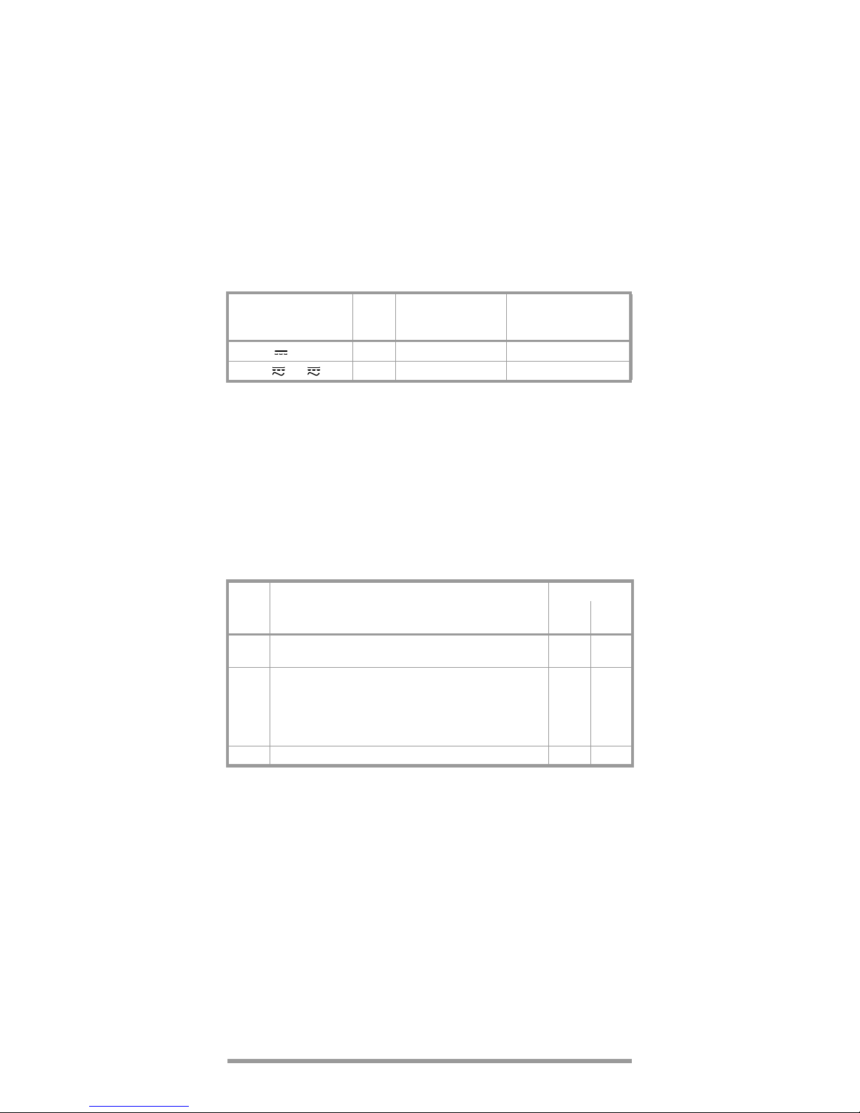
Measured Quantity
Resolution
Switching to the Next
Highest Range
at ±(... d + 1 d)
Switching to the Next
Lowest Range
at ±(... d –1 d)
V, Ω, Hz 6½ 1100 000 100000
V , mA 5½ — 100000
MAN/
AUTO
Function
Acknowledge
Display
Acoust.
Signal
Brief
Manual Mode Active:
selected measuring range is frozen
MAN 1 x
Brief
Switching sequence for:
V:
100 mV→ 1V→ 10 V→ 100 V→ 600 V→ 100 mV → ...
mA: 100 μA → 1mA→ 10 mA → 100 mA → 100 μA...
Ω: 100 Ω→ 1kΩ→ 10 kΩ→ 100 kΩ→ 1MΩ→
10 MΩ ... → 100 Ω
MAN 1 x
Long Return to Automatic Range Selection — 2 x
Page 8
8 GMC-I Messtechnik GmbH
5 Minimum and Maximum Value Storage
“MIN/MAX” with Time Stamp
Minimum and maximum measurement values can be stored to
memory with the MIN/MAX function. The most important application for this function is the determination of minimum and
maximum values during long-term observation of measurement values. It can be activated for all measuring functions.
Ð Apply the measured quantity to the instrument.
Ð Select the measuring range with MAN |AUTO.
Ð Activate the MIN/MAX function.
Ð Repeated activation of the AVE/MIN |MAX key causes switching
amongst:
MAX > t > MIN > t > MAX ...
The measuring ranges can only be selected manually when the
“MIN/MAX” function is active.
The “MIN/MAX” function is deactivated, and stored MIN and
MAX values are deleted by pressing and holding the MIN/MAX
key (approx.. 1 s), by activating the rotary switch or by switching the instrument off and back on again.
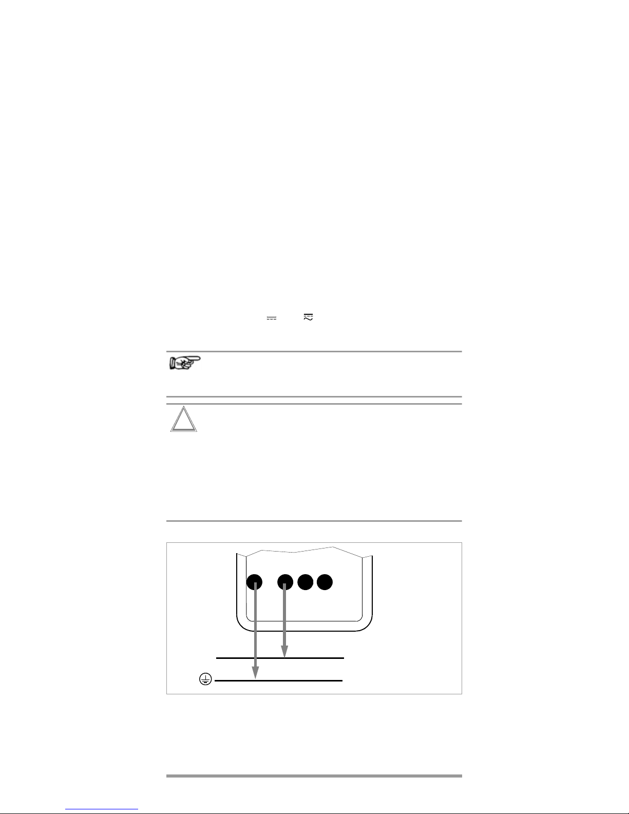
6 Voltage Measurement
Ð Depending upon the voltage to be measured, set the
rotary switch to
V or V .
Ð Connect the measurement cables as shown. The “V” jack
should be grounded.
Note!
In the 600 V range, an intermittent acoustic signal
sounds alarm if the display value exceeds 600 V.
Attention!
!
Make absolutely certain that none of the current
ranges are active when the multimeter is connected
for voltage measurements! If the breaking limit values for the electronic fuse are exceeded due to
operator error, both the operator and the instrument
are in danger! Simultaneous connection to both current and voltage measuring circuits is prohibited!
–V +
– /
⊥
+ ~
⊥
/
V
DC
V
AC
Page 9
GMC-I Messtechnik GmbH 9
GB
6.1 Zero Balancing (for V , mA , Ω and °C)
Ð Select the desired measuring range with the MAN | AUTO key.
Ð 2-Wire Resistance Measurement, Current Measurement
or Temperature Measurement with Pt100 or Pt1000:
short-circuit the positive and negative poles of sockets
„mAΩ2“ or „°C
2
“, respectively.
Voltage Measurement, Temperature Measurement with
Thermocouple or 4-Wire Resistance Measurement:
short-circuit the positive and negative poles of sockets
„V/ °CTC“ or „ΩSense“, respectively.
Ð Briefly press the MAN| AUTO and AVE/MIN|MAX keys
simultaneously.
The instrument acknowledges zero balancing with an
acoustic signal and
“000.0000” (±1 digit, decimal place
depends upon measuring range) and the “ZERO” symbol
appear at the LCD
. The previously displayed measurement
value serves as a reference value (max. ±30 000 digits).
Ð Zero balancing can be deleted:
– by pressing the MAN|AUTO key
after which deletion is acknowledged with an acoustic
signal,
– by selecting a different measuring function
– or by switching the instrument off.
Note
The zero balancing values (offset) for temperature measurement are stored to memory in the resistance and/or voltage
measurement ranges and serve as reference values.
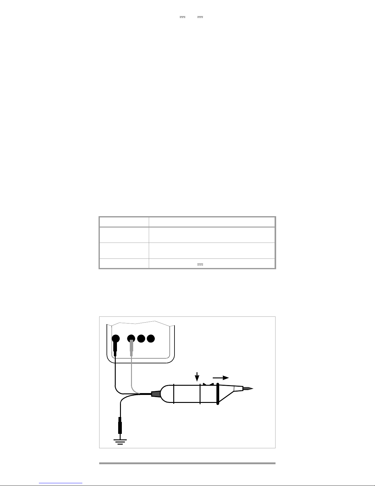
6.2 Voltage Measurements for Greater than 600 V
Voltages of greater then 600 V can be measured with a highvoltage probe, for example the HV3 or the HV30. The earthing
terminal must be connected to ground for measurements of
this type. Observe all required safety precautions!
Function Measuring Range / Function
°
C
2
Pt100: 1 kΩΩ2
Pt1000: 10 kΩΩ2
°
C
4
Pt100: 1 k ΩΩ4
Pt1000: 10 kΩΩ4
°
C
TC
100 mV V
–V
Voltage Measurements for
Greater than 600 V
with the HV3 High-Voltage
Probe
black
black
red
x1000
x100
max. 3000 V
+
Page 10

10 GMC-I Messtechnik GmbH
7 Current Measurement
Ð First disconnect supply power to the measuring circuit or the
load component, and discharge any capacitors which may
be present.
Ð Set the selector switch to “mA”.
After this selection has been made with the rotary switch, the
DC current mode is always active.
Ð Select the current type, either “DC” or “AC+DC”, which cor-
responds to the measured quantity by briefly pressing the
multifunction key. Double check for correct current type at
the LCD.
Ð Securely connect the instrument to the load component in
series as shown (without matching resistor).
Zero Balancing, see chapter 6.1, page 9
Current Measurement Tips:
• The instrument may not be used in power installations.
• The measuring circuit must be mechanically stable and protected against unintentional interruption. Conductor cross
sections and connection points must be substantial enough
to avoid excessive overheating.
• In the 100 mA measuring range, an intermittent acoustic signal warns you if the measurement value has exceeded the
measuring range upper limit value.
• The current ranges are protected by an internal 250 mA fusible link. A defective fuse can only be replaced by GMC-I
Service GmbH service personnel.
The maximum permissible voltage for the measuring current
circuit is 600 V AC/DC in the „mA“ ranges.
–mA +
– (+) / ~
+ (–) / ~
max. 600 V !
L
Page 11

GMC-I Messtechnik GmbH 11
GB
8 Resistance Measurement
Resistance measurements can be performed for devices with
high inductive or capacitive components such as motors,
transformers, coils etc.
Ð Be certain that the device under test is voltage-free.
Extraneous voltages distort measurement results!
Ð Set the rotary switch to “Ω
2
” (2-wire measurement connec-
tion) for the measurement of resistance values greater than
1kΩ, or to “Ω
4
” (4-wire measurement connection) for resis-
tance values within a range of 100 Ω to 1 kΩ.
Ð Connect the device under test as shown.
Zero Balancing for the “Ω2” and “Ω
4
” Functions
Cable and transition resistance can be eliminated with zero balancing for measurements of small resistance values.
Zero Balancing, see chapter 6.1, page 9
8.1 Continuity Testing for Resistance Measurement
Ð Set the selector switch to the position.
Ð Connect the DUT to the “Ω
2
” sockets as required for
2-wire resistance measurement.
The continuity test functions within a measuring range of
0to100Ω, and a continuous acoustic signal is generated for
values ranging from 0 to 10 Ω.
Note!
„0.L“ is displayed if the DUT is not connected.
9 Frequency Measurement
Ð Set the selector switch to the V position.
Ð Select the most favorable measuring range.
Ð Now set the selector switch to the Hz position. The selected
voltage measuring range remains active.
Ð Apply the measured quantity in the same way as for voltage
measurement.
Measurable frequencies and allowable voltages can be found
in chapter 15, page 18.
R
x
4-Wire Connection for Rx ≤
1 k
Ω
2-Wire Connection for Rx ≥ 1 k
Ω
–
Ω2 +
R
x
Current Path
–
Ω
4
+
–
Ω2 +
Page 12

12 GMC-I Messtechnik GmbH
10 Temperature Measurement
10.1 Temperature Measurement with Pt100 and Pt1000
Ð Enter the type of sensor to be used (Pt100 or Pt1000) in the
menu mode:
rAtE SEnSor ↵ Pt 100 Pt 1000 ↵
Ð Set the selector switch to
“°C
2
” for 2-wire measurement connection or
“°C
4
” for 4-wire measurement connection.
Ð Connect the sensor as shown in the following diagram:
The instrument displays the measured temperature in the unit
of measure entered in the menu mode (parameter: “tEMP”).
Compensating for Cable Resistance and Offset
Due to high measuring resolution, compensation must be
made for offset and cable resistance in the order indicated
below, especially for the 2-wire resistance temperature
measuring function (“°C2” ):
– Offset
Any remaining influence caused by the cables and contact
resistance can be eliminated by means of zero balancing (see
chapter 6.1, page 9).
– Cable Resistance
• Default setting: A preset cable resistance value is
compensated for when the default setting is used. The
preset value is 0.1 Ω which is suitable for temperature
sensors available as accessories.
• Entering a value other than the preset cable resistance value:
(value from data sheet or user calculated, see below):
Enter the utilized sensor type (Pt100 or Pt1000) and the
cable resistance value in the “Setup” menu (range: 00.01
to 99.99 Ω):
rAtE SEnSor ↵ Pt 100 (Pt 1000) ↵
Lr (lead resistance) ↵ XX.XX Ω ↵
• Calculating cable resistance:
í Heat or cool the sensor to a known temperature (e.g.
0 °C in ice water), and adjust the value in the Lr menu
until the correct measured value is displayed.
4-Wire Connection2-Wire Connection
Possible Sensors:
Z3409
TF550
TF220
TS Chipset
ϑ
–°C2+
–
°
C2+–°C4+
Page 13

GMC-I Messtechnik GmbH 13
GB
í Heat or cool the sensor to a known temperature (e.g
0 °C in ice water), and measure the sensor’s resistance
with the Ω2 function using the 1 kΩ range for Pt100
sensors, and the 10 kΩ range for Pt1000 sensors.
Cable resistance is equal to the difference between the
setpoint (100 Ω from DIN table) and the measured
value.
10.2 Temperature Measurement with Thermocouple
and Reference Junction
Ð Enter the type of thermocouple to be used (J or K) in the
menu mode: rAtE SEnSor ↵ ... J K ↵
The reference temperature can either be measured via the
internal reference junction, or can be compensated for
externally, for example through the use of ice water.
Select sensor type and internal reference temperature:
rAtE SEnSor ↵ ... IntErn ↵
or
Select sensor type and internal reference temperature in °C:
rAtE SEnSor ↵ ... E-tErn ↵
Ð Set the selector switch to “°C
TC
”.
Ð Connect the sensor as shown in the following diagram:
The instrument displays the measured temperature in the unit
of measure which has been entered in the menu mode (parameter: “tEMP”).
Note!
The internal reference temperature (from the internal
reference junction) is measured with a temperature
sensor in close proximity to the input jacks. This
temperature is somewhat higher than room temperature due to internal warming. The magnitude of this
deviation has no effect on measuring accuracy.
–°CTC+
External Reference Junction: 0°C
–°CTC+
Internal Reference Junction
°C
–
Thermocouple
Equalizing Conductor
Equalizing Conductor
Thermocouple
+
Page 14

14 GMC-I Messtechnik GmbH
11 Storing Measurement Values to Memory
The instrument is equipped with a quartz-movement synchronized measurement-value memory (128 kB), which has sufficient capacity for 30000 measurement values. Data can be
stored to intermediate memory, or transmitted directly to a PC.
Memory content can only be read out with the help of a PC, an
infrared adapter and METRAwin10/METRAHit analysis software (see chapter 14, page 17).
Preparations for Memory Mode Operation
Ð Select the desired measuring function, as well as an appro-
priate measuring range.
Ð If required, connect the mains power pack for long-term
measurement value recording.
Ð Select a sampling rate (see chapter 12.1, page 16).
Note!
Sampling rate, measuring function and measuring
range cannot be changed during operation in the
memory and transmission modes.
Starting Memory Mode Operation via Shortcut
The multimeter must be switched on.
Ð Simultaneously activate the ESC| FUNC and MENU/ON | OFF keys.
MEM, and MAN appear at the display after a few
seconds.
Exiting Memory Mode Operation via Shortcut
Ð Press any key except for MENU/ON | OFF.
or
Ð Turn the function selector switch.
Memory Occupancy Query
Memory occupancy can be queried from the INFO menu.
Occupancy is read out to the display as a percentage
(between 000.00(00)% and 100.00(00)%).
Query: rAtE InFO ↵ MEM ↵
Deleting Memory Content
Attention!
!
The function deletes all stored measurement values.
If FULL appears at the display, no more measurement values
can be stored to memory. Stored measurement values should
be uploaded and saved to a PC. The memory must be cleared
in order to record new measurement values:
rAtE InFO ↵ cLEAr ↵
12 Setting Operating and Measurement Parameters
The menu mode allows for the setting of operating parameters,
and the querying of data.
Ð The menu mode is entered by pressing the ↵ key twice if the
instrument is switched off, or only once if the instrument is
switched on and is in the measuring mode. “MENU” appears
in the bottom line of the display.
Ð Repeated activation of the keys calls up the individual
parameters, as well as the “InFo” sub-menu.
Page 15

GMC-I Messtechnik GmbH 15
GB
Ð After the desired parameter has been selected, the various
possible setting can be called up by activating the ↵ key.
Ð The desired value can be selected by repeatedly activating
the key.
Ð Acknowledge with the ↵ key and return to operation in the
measuring mode.
Ð Entry can be interrupted by pressing the ESC |FUNC key, after
which “rAtE” appears at the display. If the ESC|FUNC key is
activated once again, the instrument is returned to operation
in the measuring mode.
Ð In order to turn the multimeter off, press and hold the ↵ key
until the display goes blank.
Example: “Setting and Activating the Filter”
A interference suppressing filter can be activated for the measurement of current or voltage.
No filter: value = 1, greatest level of filtering: value = 16
rAtE FILt 1 2 4 .
or in abbreviated form:
rAtE FILt ↵ 1 2 4 ↵ .
Paths to Measuring and Operating Parameters
↵
↵
rAtE OFF, 10 ms, 100 ms, 1 s, 10 s, 60 s
Addr 1, 2, 3, 4, 5, 6, 7 ... 15
rS 232 9600, 19200
InFo tESt, uEr, MEM, CLEAr, CALdAtE, CALdUE
SEnSor Pt 100, Pt 1000, J, K, IntErn, E-tErn
tEMP °C, °F
FILt 1, 2, 4, 8, 16
Parameter
↵
↵
Menu Mode
MENU/
ON|OFF
rate
MENU
Settings / Adjustable Values
↵
Page 16

16 GMC-I Messtechnik GmbH
12.1 Description of Measurement Parameters
and Memory Commands
rAtE – Sampling Rate (storage or measuring rate)
The sampling rate determines the interval, after which the
respective measurement values are transmitted to the interface
or the measurement value memory.
The following sampling rates are possible:
rAtE ↵ OFF, 10 ms, 100 ms, 1 s, 10 s, 60 s.
If OFF is selected, individual measurement values can be
stored to memory by simultaneously activating the ESC |FUNC
and ↵ keys.
The display is reduced to 5½ places for the 100 ms sampling
rate, and to 4½ places for 10 ms.
Addr and rS232
See chapter 13.1, page 17.
SEnSor and tEMP
See chapter 10, page 12.
FILt – Filter
See above example.
12.2 InFo – Information Menu
tESt – RAM Test
Starting the RAM test:
rAtE InFO ↵ tESt ↵
No other functions may be activated during the RAM test. Two
test samples are written to memory, and are subsequently
read out. If the test is completed successfully, “Good” appears
at the display.
See chapter 17, page 26, for additional display messages.
uEr – Firmware Version
The revision level of the current firmware version is briefly
displayed: rAtE InFO ↵ uEr ↵ 070102.
MEM – Query Memory Occupancy
See description in chapter 11, page 14.
CLEAr – Delete Memory Content
See description in chapter 11, page 14.
CALdAtE – Date of Last Calibration
The date of the last calibration is briefly displayed:
rAtE InFO ↵ CALdAtE ↵ 020399.
CALdUE – Next Recommended Calibration
The due date for the next recommended calibration is briefly
displayed: rAtE InFO ↵ CALdAtE ↵ 020300.
12.3 Default Settings
Selected parameter settings for ADDR, RS232, CALDATE,
CALDUE and VER are retained in the memory after the multimeter is switched off. All other parameter changes are lost,
and the default settings are once again active when the instrument is switched back on.
13 Data Transmission via RS232 Interface
The multimeter is equipped with an infrared interface for the
transmission of measurement data to a PC. Measurement values are optically transmitted via infrared light through the housing to an interface adapter (accessory), which is plugged into
the multimeter. The RS232 interface at the adapter allows for
connection to a PC via an interface cable. Furthermore, commands and parameters can be uploaded from the PC to the
multimeter.
Page 17

GMC-I Messtechnik GmbH 17
GB
For example:
• Select and read out measuring parameters
• Select measuring function and range
• Start measurement
• Read out measurement values
(online readout with simultaneous measurement:
shortest possible sampling period is 100 ms)
The interface is always active if the instrument is switched on.
13.1 Selecting Interface Parameters
Addr – Address
If several multimeters, interfaces or memory adapters are
connected to the PC, each device requires its own address.
Address number 1 should be assigned to the first device, 2 to
the second device etc.
rS232 – Baud Rate / Transmission Mode
The baud rate can be selected, and operation in the transmission mode can be simultaneously activated with the rS232
command. Transmission can be interrupted with the MENU/
ON|OFF key:
rAtE rS232 ↵ 9600 19200 ↵ .
14 Accessories
BD232 Interface adapter (without memory) allows for remote
control of the multimeter, as well as the transmission of
measurement data from up to six multimeters to the PC
.
METRAwin10/METRAHit Software
METRAwin10/METRAHit software is used to process and
display measurement data at a PC. Sampling can be triggered
manually with an adjustable sampling interval, or in a signal
dependent fashion. Storage of data in ASCII format can be
controlled with two trigger thresholds per measuring channel,
as well as by means of system time.
The following prerequisites must be fulfilled for the implementation of METRAwin10/METRAHit:
Software Requirements:
– MS WINDOWS XP, VISTA or 7
Hardware Requirements:
– IBM compatible Windows PC, Pentium processor with
200 MHz or better and at least 64 MB RAM
– SVGA monitor with at least 1024 x 768 pixels
– Hard disk with at least 40 MB available memory
– CD-ROM drive
– Microsoft compatible mouse
– Windows-supported printer
– 1 USB port for using USB-HIT
Page 18

18 GMC-I Messtechnik GmbH
15 Characteristic Values
Measuring
Function
Measuring Range
Resol. at Meas. Range Upper Limit
1200 000 1)120 000 1)12 000
1)
V
100 mV 0.1 μV1μV10μV
1V 1μV10μV 100 μV
10 V 10 μV 100 μV1mV
100 V 100 μV1mV10mV
600 V 1 mV 10 mV 100 mV
mA
100 μA 100pA 1nA 10nA
1 mA 1 nA 10 nA 100 nA
10 mA 10 nA 100 nA 1 μA
100 mA 100 nA 1 μA10μA
Ω
100 Ω 0.1 mΩ 1mΩ 10 mΩ
1kΩ 1mΩ 10 mΩ 100 mΩ
10 kΩ 10 mΩ 100 mΩ 1 Ω
100 kΩ 0.1 Ω 1 Ω 10 Ω
1MΩ 1 Ω 10 Ω 100 Ω
10 MΩ 10 Ω 100 Ω 1000 Ω
Ω
100 Ω 10 mΩ
Resolution
Hz
1Hz
2)
to
100 kHz
0.000 001 Hz
0.1 Hz
Sensor
°C/°F
– 200.0 ... + 850.0 °C 0.01 °C Pt100 / Pt1000
– 210.0 ... +1200.0 °C
0.1 °C
J (Fe-CuNi)
– 270.0 ... +1372.0 °CK (NiCr-Ni)
Input Impedance
V
100 mV > 1 GΩ >1GΩ //<50pF
1V >1GΩ 10 MΩ //<50pF
10 V 10 MΩ 10 MΩ //<50pF
100 V 10 MΩ 10 MΩ //<50pF
600 V 10 MΩ 10 MΩ //<50pF
Approx. Voltage Drop at Meas. Range Upper Limit
mA
100 μA 150 mV 150 mV
1 mA 1.5 V 1.5 V
10 mA 150 mV 150 mV
100 mA 1.5 V 1.5 V
Open-Circuit Voltage
Meas. Current at Meas.
Range Upper Limit
Ω
100 Ω 3V 1mA
1kΩ 3V 1mA
10 kΩ 3 V 100 μA
100 kΩ 3V 10μA
1MΩ 3V 1μA
10 MΩ 3 V 100 nA
Ω
100 Ω 3V 1mA
Page 19

GMC-I Messtechnik GmbH 19
GB
1)
Number of display places: 6½ for DC and Ω, 5½ for AC
Resolution is adjustable for the storage and the transmission of
measurement values (see chapter 12.1).
2)
Lowest measurable frequency for sinusoidal measurement signals,
combined measurement of period duration and frequency
3)
At 0 ° ... + 40 °C
4)
As of 10% of the measuring range. See page 20 for influences.
5)
DC component: max. 10% of reading.
6)
ZERO is displayed when the “Zero Balancing” function is active.
7)
Range 100 mV : UE= 10 . . . 30 mV
eff
additional error: +0.5% range
1V :UE= 0.1 . . .0,3 V
eff
additional error: +0.3% range
8)
Plus sensor deviation
Measuring
Range
Intrinsic Uncertainty at max. Resolution
at Reference Conditions
Frequency
Range
in Hz
Overload
Capacity
3)
±(...% of rdg. + % of range)
4) 5)
Value Duration
100 mV 0.005 + 0.0006
6)
0.08 + 0.06
7)
45 … 65
600 Veff
sine
contin-
uous
0.1 + 0.1 10 … 1 k
5 + 0.5 1 k … 5 k
1 V 0.0030 + 0.0004
0.08 + 0.06
7)
45 … 65
0.1 + 0.1 15 … 1 k
0.2 + 0.1 10 … 10 k
5 + 0.5 10 k … 50 k
10 V 0.0030 + 0.0004
0.08 + 0.06
0.1 + 0.1
0.2 + 0.1
1 + 0.1
3 + 0.1
45 … 65
15 … 1 k
10 … 10 k
10 k … 50 k
50 k … 100 k
100 V 0.0030 + 0.0006
600 V 0.0040 + 0.0010
0.08 + 0.06 45 … 65
0.2 + 0.1 10 … 1 k
3 + 0.1 1 k … 10 k
4) 5)
100 μA
0.02 + 0.002
0.08 + 0.06
0.1 + 0.1
0.2 + 0.1
45 … 65
10 … 1 k
1 k … 5 k
0.18 A/
600 Veff
contin-
uous
1mA
10 mA
100 mA
±(...% of rdg. + % of range)
100 Ω 0.005 + 0.001
6)
600 Veff
sine
10 min.
1kΩ 0.005 + 0.001
6)
10 kΩ 0.005 + 0.001
100 kΩ 0.005 + 0.001
1MΩ 0.05 + 0.002
10MΩ 0.5 + 0.02
Ω
0.05 + 0.01
1 Hz to 100
kHz
0.05 % of rdg. 600 V
contin-
uous
Pt 100/
Pt 1000
–200.0 ... +850.0 °C ±(0.05 % of rdg. + 0.08 K)
8)
600 Veff
sine
10 min.
J – 210.0 ... + 1200.0 °C
±(0.7 % of rdg. + 0.3 K)
8)
600 Veff
sine
K – 270.0 ... +1372.0 °C
Page 20

20 GMC-I Messtechnik GmbH
Influence Variables and Effects
1)
With zero balancing
2)
Inherent deviation values valid as of a display value
of at least 10% of the measuring range.
3)
Except for sinusoidal waveform
Influence
Variable
Influence Range
Measured Quantity /
Measuring Range 1)
Influence Effect
ppm/K
Temperature
0 °C ...
+21 °C
and
+25 °C ...
+40 °C
V8
V 100
mA 20
mA 100
100 Ω ... 100 kΩ 8
1MΩ 15
10 MΩ 100
Hz 50
°C15
Influence
Variable
Influence Range
Measured Quantity /
Measuring Range 1)
Influence Effect
3)
Measurement
Quantity
Waveform
Crest
factor
CF
1 ... 3
V, mA
±0.2% of rdg.
> 3 ...
5
±0.5% of rdg.
10 ±2% of rdg.
Influence
Variable
Influence Range
Measured Quantity /
Measuring Range 1)
Influence Effect
Relative
Humidity
75%
3 days
device off
V, m A , Ω
Hz
°C
1 x inherent deviation
Influence
Variable
Influence Range
Measuring
Range
Damping
±dB
Common-
Mode
Interference
Voltage
Interference quantity max. 600 V V > 90 dB
Interference quantity max. 600 V
50 Hz, 60 Hz sine
100 mV ...
10 V
> 80 dB
100 V > 70 dB
600 V > 60 dB
Series-Mode
Interference
Voltage
Interference quantity V ,
respective measuring range nominal value,
max. 600 V , 50 Hz, 60 Hz sine
V > 60 dB
Interference quantity max. 600 V V > 60 dB
1
10
CF
0
50000 10000075000
Voltage and Current Measurement
The allowable crest factor (CF) for the periodic quantity to be measured
is dependent upon the displayed value:
Digits
5
Page 21

GMC-I Messtechnik GmbH 21
GB
Reference Conditions
Ambient
Temperature
+23 °C ±2K
Relative Humidity
40 ... 60%
Measurement
Quantity Frequency
45 ... 65 Hz
Measurement
Quantity Waveform
sine
Battery Voltage
3V ±0.1 V
Power Pack Voltage
5V ±0.2 V
Response Time
After Manual Range Selection at max. Resolution
Measuring Cycle
Display
LCD field (65 mm x 30 mm) with digital display, including
display of unit of measure, current type and various special
functions.
Type / Char. Height
7 segment / 12 mm
Resolution
6½ digits
Overload Display
“OL” is displayed as of
1250000 counts
Polarity Display
“–” sign is displayed when plus pole
is connected to “–V”
Display Update
V, mA , Ω, °C/°F
once per second
Hz
1 to 0.5 times per second
Measured Quantity /
Measuring Range
Response Time
Measured Quantity
Step Function
V, V,
A, A
max. 2 s
from 0 to 80% of
measuring range upper limit
100 Ω ... 1 MΩ max. 2 s
from ∞ to 50% of
measuring range upper limit
10 MΩ max. 5 s
Continuity < 30 ms
°C (Pt100) max. 2 s
from 0 to 50% of
measuring range upper limit
>10 Hz max. 2 s
Measuring Function
Interval Depending upon Resolution
1 200 000 120 000 12 000
V , mA 1 s 0.1 s 0.01 s
V , mA — 0.1 s 0.01 s
Ω / °C 1 s 0.1 s 0.01 s
°C (K, J) 1 s 0.1 s 0.01 s
Hz 1 s (≤ 2 s at 1 Hz) — —
Page 22

22 GMC-I Messtechnik GmbH
Power Supply
Batteries
2 AA size batteries
alkaline manganese cells per
IEC LR6
Service Life
Battery Test
Automatic display of “ ”
when battery voltage
falls to below approx. 2.3 V.
Battery Saver Circuit
The instrument switches itself off automatically if the measurement value remains unchanged for about 10 minutes, and if
none of the operating elements are activated during this time.
This function is disabled in the transmission and menu modes,
or if “continuous on” has been activated.
Fuses
The current measuring ranges are protected by an internal
250 mA fusible link. A defective fuse can only be replaced by
GMC-I Service GmbH service personnel.
The voltage of the measuring current circuit may not exceed
600 V
eff
.
Electrical Safety
Protection Class
II per IEC/EN 61010-1:2010
/VDE 0411-1:2011
Measuring Category
II
Operating Voltage
600 V
Pollution degree
2
Test Voltage
3.7 kV~ per IEC/EN 61010-1:2010
/VDE 0411-1:2011
Electromagnetic Compatibility (EMC)
Interference Emission
EN 61326-1:2006 class B
Interference Immunity
EN 61326-1:2006
EN 61326-2-1:2006
Measuring Function
(with 2.5 Ah alkaline manganese cells)
Power
Consumption in mA
Service Life in
Hours
V DC, mA DC, °C/°F 100 16
V (AC + DC), mA (AC + DC) 105 15
Transmission mode, sampling rate: 100 ms
9600 baud 114
19200 baud 108
Transmission mode, sampling rate: 10 ms
9600 baud 156
19200 baud 146
Page 23

GMC-I Messtechnik GmbH 23
GB
Ambient Conditions
Operating Temp.
− 5 °C ... + 50 °C
Storage Temperature
−25 °C ... +70 °C (without batteries)
Relative Humidity
max. 75%, no condensation
allowed
Elevation
to 2000 m
Deployment
indoors,
outdoors: only in the specified
ambient conditions
Warm-Up Time
5 min.
Mechanical Design
Protection
instrument: IP 50,
connector jacks: IP 20
Extract from table on the meaning of IP
codes
Dimensions
84 mm x 195 mm x 35 mm
Weight
approx. 350 gr. with batteries
Data Interface
Data Transmission
optical with infrared light,
through the housing (patented)
With interface adapter as accessory
Typ e
RS232C, serial, per DIN 19241
Baud Rate
Bidirectional
BD232: 9600 baud
IP XY
(1st digit X)
Protection against
foreign object entry
IP XY
(2nd digit Y)
Protection against the
penetration of water
2 ≥ 12.5 mm dia. 0 not protected
5 dust protected 0 not protected
Page 24

24 GMC-I Messtechnik GmbH
16 Maintenance – Recalibration
Attention!
!
Disconnect the instrument from the measuring
circuit before opening to replace batteries!
16.1 Batteries
Note!
Battery Replacement
Stored measurement values are deleted when the
battery is replaced. We recommend connecting the
power pack, or uploading data to a PC with the help
of METRAwin10/METRAHit software, before
replacing batteries in order to prevent data loss.
Operating parameters remain in memory.
Before initial start-up, or after storage of your instrument, make
sure that no leakage has occurred at the instrument battery.
Repeat this inspection at regular intervals.
If battery leakage has occurred, electrolyte from the battery
must be carefully and completely removed with a damp cloth,
and a new battery must be installed.
If the “ ” symbol appears at the LCD, you should replace the
batteries as soon as possible. You can continue to take
measurements, but reduced measuring accuracy may result.
The instrument works with two 1.5 V batteries per IEC R6 or
IEC LR6, or with corresponding, rechargeable NiCd batteries.
Battery Replacement
Ð Lay the instrument onto a flat surface with the front panel
facing down, loosen the two screws at the back and lift out
the housing base starting at point (a).
Ð Remove the batteries from the battery compartment.
Ð Insert two 1.5 V mignon cells into the battery compartment
in the direction indicated by the polarity symbols.
Ð Important for reassembly: First set the housing base onto the
housing top and align accurately (see photo below). Then
press the two housing halves together, first at the bottom
front (a), and then at the top front (b).
Ð Retighten the housing base with the two screws.
Ð Please dispose of depleted batteries properly!
(b) (a)
Page 25

GMC-I Messtechnik GmbH 25
GB
16.2 Power Pack
Use only the NA HIT 2X power pack for power supply to your
instrument. The highly insulated cable assures safety for the
operator, and the power pack provides for reliable electrical
isolation. When a mains power pack is used, the batteries
inside the instrument are disconnected automatically.
Note!
We recommend that zero balancing be performed in
accordance with chapter 6.1, page 9, if the power
pack is used.
16.3 Housing
No special maintenance is required for the housing. Keep
outside surfaces clean. Use a slightly dampened cloth for
cleaning. Avoid the use of cleansers, abrasives or solvents.
16.4 Recalibration
The respective measuring task and the stress to which your
measuring instrument is subjected affect the ageing of the
components and may result in deviations from the guaranteed
accuracy.
If high measuring accuracy is required and the instrument is
frequently used in field applications, combined with transport
stress and great temperature fluctuations, we recommend a
relatively short calibration interval of 1 year. If your measuring
instrument is mainly used in the laboratory and indoors without
being exposed to any major climatic or mechanical stress, a
calibration interval of 2-3 years is usually sufficient.
During recalibration* in an accredited calibration laboratory
(DIN EN ISO/IEC 17025) the deviations of your instrument in
relation to traceable standards are measured and documented. The deviations determined in the process are used for
correction of the readings during subsequent application.
We are pleased to perform DAkkS or factory calibrations for
you in our calibration laboratory. Please visit our website at
www.gossenmetrawatt.com (→ Company → DAkkS Calibration Center or → FAQs → Calibration questions and answers).
By having your measuring instrument calibrated regularly, you
fulfill the requirements of a quality management system per
DIN EN ISO 9001.
* Verification of specifications or adjustment services are not part of the cali-
bration. For products from our factory, however, any necessary adjustment
is frequently performed and the observance of the relevant specification is
confirmed.
Country Type Article No.
Germany NA HIT 2X Z218H
Page 26

26 GMC-I Messtechnik GmbH
16.5 Device Return and Environmentally Compatible Disposal
The instrument is a category 9 product (monitoring and control
instrument) in accordance with ElektroG (German Electrical
and Electronic Device Law). This device is subject to the RoHS
directive. Furthermore, we make reference to the fact that the
current status in this regard can be accessed on the Internet at
www.gossenmetrawatt.com by entering the search term
WEEE.
We identify our electrical and electronic devices in
accordance with WEEE 2012/19/EU and ElektroG
with the symbol shown to the right per DIN EN
50419. These devices may not be disposed with
the trash. Please contact our service department
regarding the return of old devices.
If you use batteries or rechargeable batteries in your instrument or
accessories which no longer function properly, they must be
duly disposed of in compliance with the applicable national
regulations.
Batteries or rechargeable batteries may contain harmful substances or heavy metal such as lead (PB), cadmium (CD) or
mercury (Hg).
They symbol shown to the right indicates that batteries or rechargeable batteries may not be disposed of
with the trash, but must be delivered to collection
points specially provided for this purpose.
17 Multimeter Display Messages
* A hardware problem may have occurred. Please send your multimeter to our
Repair and Replacement Parts Service department.
Message Function Significance
FAIL RAM test RAM test failed *
Good RAM test RAM test successfully completed
all operating modes battery voltage has dropped to below 2.3 V
FULL transmission mode measurement value memory is full
OL measuring indicates overload
Pb Cd Hg
Page 27

GMC-I Messtechnik GmbH 27
GB
18 Repair and Replacement Parts Service
Calibration Center *
and Rental Instrument Service
If required please contact:
GMC-I Service GmbH
Service Center
Thomas-Mann-Strasse 20
90471 Nürnberg • Germany
Phone +49 911 817718-0
Fax +49 911 817718-253
E-mail service@gossenmetrawatt.com
www.gmci-service.com
This address is only valid in Germany. Please contact our
representatives or subsidiaries for service in other countries.
* DAkkS Calibration Laboratory for Electrical Quantities
D-K-15080-01-01 accredited per DIN EN ISO/IEC 17025:2005
Accredited measured quantities: direct voltage, direct current
values, DC resistance, alternating voltage, alternating current
values, AC active power, AC apparent power, DC power,
capacitance, frequency and temperature
Competent Partner
GMC-I Messtechnik GmbH is certified per
DIN EN ISO 9001:2008.
Our DAkkS calibration laboratory is accredited by the Deutsche
Akkreditierungsstelle GmbH (National accreditation body for
the Federal Republic of Germany) in accordance with DIN EN
ISO/IEC 17025:2005 under registration number D-K-1508001-01.
Our competence in the field of metrology covers test reports,
proprietary calibration certificates and DAkkS calibration certificates.
Our range of services is complemented by a Test Equipment
Management service which is provided free of charge.
An on-site DAkkS calibration station is an integral part of our ser-
vice department. If any faults are detected during calibration,
our specialists are able to carry out the necessary repairs with
original replacement parts.
Needless to say, in our function as calibration laboratory, we
calibrate all instruments, irrespective of the manufacturer.
19 Manufacturer’s Guarantee
All METRAHIT digital multimeters and calibration instruments
are guaranteed for a period of 3 years after shipment. The
manufacturer’s guarantee covers materials and workmanship.
Damages resulting from use for any other than the intended
purpose or operating errors, as well as any and all consequential damages, are excluded.
The calibration certificate confirms that the product conformed
to the specified technical data at the time of calibration. We
guarantee the observance of the specified technical data within
the admissible tolerance limits for a period of 12 months from
delivery.
Page 28

Edited in Germany • Subject to change without notice • A PDF version is available
on the Internet
GMC-I Messtechnik GmbH
Südwestpark 15
90449 Nürnberg • Germany
Phone +49 911 8602-111
Fax +49 911 8602-777
E-Mail info@gossenmetrawatt.com
www.gossenmetrawatt.com
20 Product Support
If required please contact:
GMC-I Messtechnik GmbH
Product Support Hotline
Phone +49 911 8602-0
Fax +49 911 8602-709
E-Mail support@gossenmetrawatt.com
DAkkS Calibration Certificate Reprints
If you need to order a reprint of the DAkkS calibration certificate for your instrument, please include the ID number shown
in the uppermost and lowermost fields of the red calibration
seal. We do not need the instrument’s serial number.
 Loading...