

Page 1
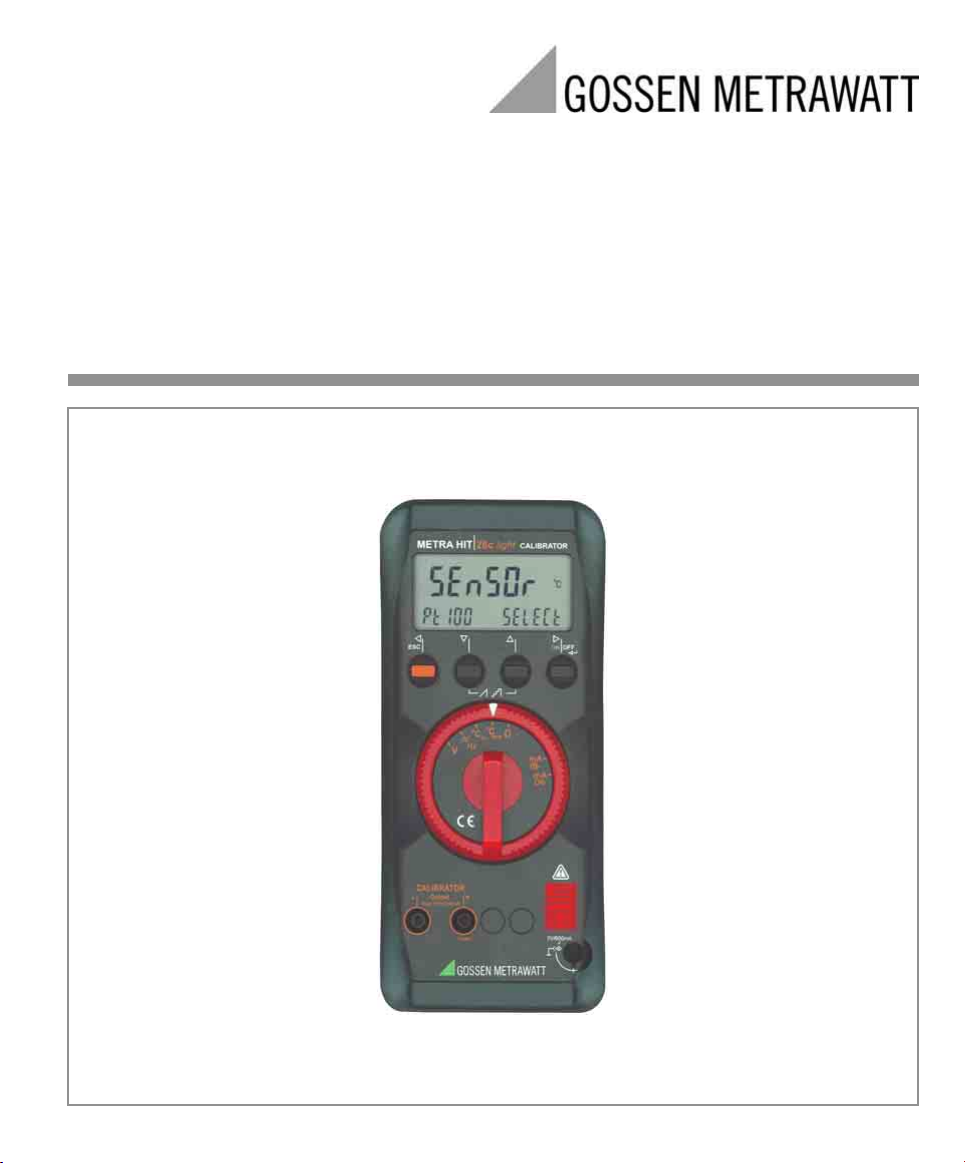
Operating Instructions
METRA HIT28c light
Calibrator
3-349-317-15
6/2.05
Page 2
1
1
2
3
4
5
6
8
9
7
No measuring input !
!
Do not apply interference voltage
except current sink
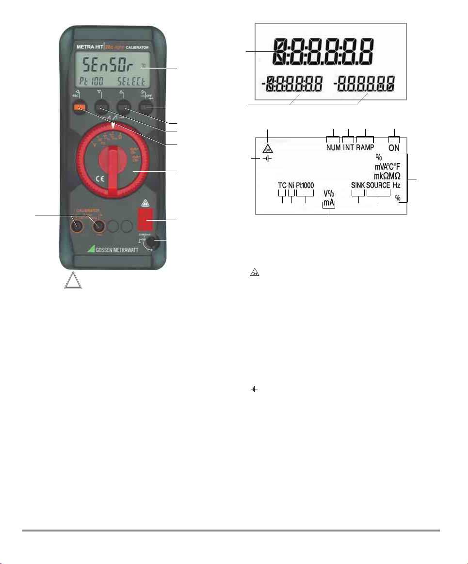
1Display (LCD)
2 ON| OFF key
! Cursor position to the right
Operating mode menu:
↵ (ENTER) Changeover to sub-menus /
3 " Increase values
Operating mode menu: Selection of individual menu items
4 # Decrease values
Operating mode menu: Selection of individual menu items
5 ESC key for selecting ranges or functions
$ Cursor position to the left
Operating mode menu: Exit menu level and return to a higher level,
6 Rotary switch for simulation functions
7 Connector jack for NA5/600 power pack
8 Connector jacks for calibrator output
9 DKD calibration mark, see page 4
acknowledgement of entries
against direction of flow
in direction of flow
exit parameters configuration
without saving data
2
3
4 57
6
13
12 11 11 10 9
8
Symbols used in the Digital Display
1 Main display with decimal point and polarity display
2 Auxiliary display with decimal point and polarity display
3 : Simulator in continuous operation
4 NUM: Numeric entry of output signal
5 INT: Interval sequence active
6 RAMP:Ramp function active
7 ON: Calibrator output is active
8 Unit of measure (if blinking, refer to chapter 13 on page 24)
9 SOURCE: Current source is active
10 SINK: Current sink is active
11 Ni/Pt1000: Selected temperature sensor
12 TC: Thermocouple
13 : Low battery voltage (< 3.5 V), replace batteries
8
2 GOSSEN METRAWATT GMBH
Page 3

Table of Contents
Page
1 Safety Features and Precautions ...............................3
2 Initial Start-Up ............................................................5
3 Voltage Simulator .......................................................6
4 Pulse and Frequency Generator (positive square-wave
pulse) .........................................................................6
5 Resistance Simulation [Ω] .........................................7
6 Temperature Simulation [°C] .....................................8
6.1 Temperature Simulation of Resistance Temperature
Detectors – Position °C
6.2 Temperature Simulation of Thermocouples – Position °C
. .................................................... 8
RTD
TC
. ..... 8
7 Current Source and Current Sink .............................10
7.1 Current Sink – Simulation of a 2-Wire Transmitter ................. 10
7.2 Current Source .................................................................... 10
8 Interval Functions, Ramp Functions and Procedures 11
8.1 Interval Sequences – INT Function ......................................... 11
8.2 Read-Out a Periodic Ramp – RAMP Function .......................... 14
9 Using the Menus – from the Initial InFO Menu to
Operating Parameters ..............................................16
9.1 Activating the Default Values .................................................18
9.2 Transmission Mode Operation with RS 232 Interface ..............18
10 Accessories ..............................................................19
11 Characteristic Values ...............................................20
12 Maintenance ............................................................23
12.1 Battery ................................................................................. 23
12.2 Power Pack .......................................................................... 23
12.3 Fuses ................................................................................... 24
12.4 Housing ................................................................................ 24
13 Calibrator Messages ................................................24
1 Safety Features and Precautions
You have selected an instrument which provides you with a
high level of safety.
This instrument fulfills the requirements of the applicable
European and national EC guidelines. We confirm this with
the CE marking. The relevant declaration of conformity can
be obtained from GOSSEN METRAWATT GMBH.
The instrument is manufactured and tested in accordance
with safety regulations IEC 61010–1:2001/DIN EN 61010–
1:2001/ VDE 0411–1:2002. When used for its intended purpose, safety of the operator, as well as that of the instrument,
is assured. However, their safety is not guaranteed, if the
instrument is used improperly or handled carelessly.
In order to maintain flawless technical safety conditions, and to
assure safe use, it is imperative that you read the operating instructions thoroughly and carefully before placing your instrument into
service, and that you follow all instructions contained therein.
14 Repair and Replacement Parts Service
DKD Calibration Lab
and Rental Instrument Service .................................25
15 Warranty ...................................................................25
16 Product Support .......................................................25
GOSSEN METRAWATT GMBH 3
Page 4

Observe the following safety precautions:
• The instrument may only be operated by persons who
are capable of recognizing contact hazards and taking
the appropriate safety precautions. Contact hazards exist
anywhere, where voltages of greater than 33 V RMS may
occur.
Attention!
!
The calibrator has been designed for safe connection
to signal circuits.
Maximum allowable voltage between connector jacks (7)
amongst themselves and earth is 15 V.
If U
or I
max
blows.
is exceeded, the integrated 250 V fuse
max
• Be prepared for the occurrence of unexpected voltages
at devices under test (e.g. defective devices). For example, capacitors may be dangerously charged.
• Make certain that the measurement cables are in flawless
condition, e.g. no damage to insulation, no interruptions
in cables or plugs etc.
• No functions may be performed with this instrument in
electrical circuits with corona discharge (high-voltage).
•
For this reason,
never confuse a
calibrator with a
multimeter.
• When necessary, use a multimeter to make sure that no
dangerous contact voltages are present in the signal circuits to which the instrument is to be connected.
• In order to prevent damage to the instrument, observe
the maximum allowable voltage and current values indicated at the jacks.
With the exception of the resistance simulation and mA
SINK operating modes, the connected signal circuits
should not feed any voltage or current back to the calibrator.
In order to avoid damage to the instrument when interference voltages are applied (within allowable limit values),
the mA SINK and mA SOURCE measuring circuit is
equipped with a fuse F3, which makes this measuring
circuit highly resistive if excessive current should occur in
the event of a fault for the duration of overloading.
Meanings of symbols on the instrument
!
Warning concerning a source of danger
(Attention: observe documentation!)
Earth
Continuous, doubled or reinforced
insulation
Indicates EC conformity
DKD calibration mark (red seal):
B0730
DKD-K19701
01-08
Consecutive number
German Calibration Service - Calibration Laboratory
Registration number
Date of calibration (year–month)
Repair, Parts Replacement and Balancing
When the instrument is opened, voltage conducting parts
may be exposed. The instrument must be disconnected from
the circuit before the performance of repairs, the replacement
of parts or balancing. If balancing, maintenance or repair of a
live open instrument is required, this may only be carried out
by trained personnel who are familiar with the dangers
involved.
Defects and Extraordinary Strains
If it may be assumed that the instrument can no longer be
operated safely, it must be removed from service and
secured against unintentional use.
Safe operation can no longer be relied upon,
• If the instrument or the test probes are damaged
• If the instrument no longer functions
• After long periods of storage under unfavorable
conditions.
Warning!
The instrument may not be operated in explosive atmospheres, or connected to intrinsically safe electrical circuits.
4 GOSSEN METRAWATT GMBH
Page 5

2 Initial Start-Up
Battery operation
Be certain to refer to chapter 12.1 regarding correct battery
installation.
Switching the Instrument Off Manually
➭ Press and hold the ON|OFF key until OFF appears at the
display.
Shutdown is acknowledged with two brief acoustic signals.
Attention!
!
As a result of internal battery voltage monitoring, the
instrument may respond as follows if the battery
charge level is low:
– Cannot be switched on
– Shuts back down immediately
– Shuts back down in the event of loading at the
output.
If this is the case, replace the batteries in
accordance with chapter 12.1, or continue
work with the power pack if possible.
Operation with mains adapter
(accessory equipment, not included as a standard feature)
During power supply via mains adapter NA5/600, the
inserted batteries are cut off electronically so that they rmay
remain in the instrument, see also chapter 12.2. If rechargeable batteries are used, they must be charched outside the
instrument.
Switching the Instrument On Manually
➭ Press the ON| OFF key.
Power-up is acknowledged with a brief acoustic signal.
As long as the key is held depressed, all of the segments
at the liquid crystal display (LCD) are illuminated. The
LCD is shown in the diagram on page 3.
The instrument is ready for calibration as soon as the key
is released.
Switching the Instrument On with a PC
After transmission of a data frame from the PC, the simulator
is switched on. See also chapter 9.2.
Automatic Shutdown of the Calibrator
The simulator deactivates the output quantity after 5 minutes
of inactivity. 5 minutes later, the instrument is switched off.
Shutdown is acknowledged with a brief acoustic signal.
The continuous operation mode is not affected by automatic
shutdown.
Disabling Automatic Shutdown
The instrument can be set to continuous operation.
➭ Press and hold the ESC|FUNC key and then switch the in-
strument on by pressing the ON|OFF key. Continuous operation is indicated at the display with the symbol.
Note!
☞
Electrical discharge and high frequency interference
may cause incorrect displays to appear, and may disable the simulator. In such cases, switch the instrument off and back on again in order to reset. If the
problem persists, briefly dislodge the battery from the
connector contacts.
Setting Time and Date
See chapter 9 on page 16.
GOSSEN METRAWATT GMBH 5
Page 6
3 Voltage Simulator
The instrument includes the following simulator functions:
Direct voltage V DC, frequency f, resistance Ω, temperature
°C (for resistance thermometers or thermocouples) and current mA DC.
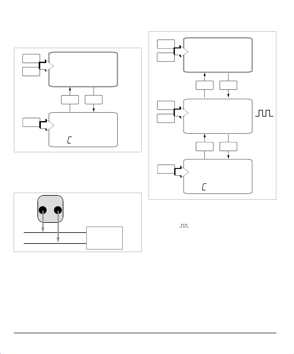
#"
$ !
Voltage
Simulator Value
1.3520
0.,3-15
NUM ON
V
V
4 Pulse and Frequency Generator (positive square-wave
pulse)
#"
$ !
Frequency
0100.0
05.000
(... 3x) (... 4x)
NUM ON
V
↵
ESC
Hz
Hz
↵
NUM ON
#"
Voltage
Range
Voltages can be simulated within the following ranges:
0 … ±300 mV, 0 … 3 V, 0 … 10 V and 0 … 15 V.
The resistance of the interconnected circuit should not be any
less than 1 kΩ.
➭ Connect the DUT with the measurement cables as
shown.
–
➭ Select the V calibration function with the rotary switch.
➭ Setting the voltage simulation value:
Press $! keys to select the decade, i.e. the position of
the digit you wish to change, and press #" keys to set
the respective digit.
➭ Changing the voltage simulation value:
Press the ESC key until you proceed to the voltage range
sub-menu. Press #" keys to set the respective digit.
Press ↵ key to return to the main menu.
0 .3- 15
sele t range
CALIBRATOR
Output
+
DUT
e. g.
Measuring transducer
ESC
–
+
(... 2x)
V
Input
#"
$ !
Voltage
Amplitude
05.000
0100.0
#"
Voltage
Range
Voltage and frequency can be generated independent of one
another with the frequency generator.
The output signal is a square wave. The resistance of the
interconnected circuit should not be any less than 1 kΩ.
➭ Select the /Hz calibration function with the rotary
switch.
➭ Setting voltage amplitude (0 … 15 V):
Press the ESC key until you proceed to the menu for setting voltage amplitude.
The decade (i.e. the position of the digit to be changed) is
selected with the $! keys, and the respective digit is
set with the #" keys.
➭ Changing the voltage simulation range:
Press the ESC key until you proceed to the voltage range
sub-menu. Press #" keys to set the respective digit.
Press ↵ key to return to the main menu.
➭ Setting the frequency value (1 … 1000 Hz):
Press ↵ key until you proceed to the frequency main
menu. Press $! keys to select the decade, i.e. the po-
sition of the digit you wish to change, and press #"
keys to set the respective digit.
0 .3- 15
sele t range
NUM ON
↵
NUM ON
ESC
V
Hz
(... 3x)
V
6 GOSSEN METRAWATT GMBH
Page 7
Frequency settings of 29 Hz and greater can only be selected
in a limited fashion.
Note!
☞
The following error messages may appear:
“HiCurr” (high current – current at overload limit)
where I
(out of limits – limit value violation) where I > 30 mA.
The simulator is switched off.
Attention!
!
In this operating mode interference voltages must not
be applied to the calibrator jacks.
In the event of operating errors, such as the shortterm application of a high interference voltage, the instrument/calibrator is protected by a replaceable
fuse F3, see chapter 12.3.
= 18 mA, “0ut 0l” and 3 acoustic signals
max.
5 Resistance Simulation [Ω]
Resistance can be simulated by means of 2-wire connection
within the following range: 5 … 2000 Ω.
Note!
☞
The following error messages may appear:
“HiCurr” (high current – current too high) where
I > 4.5 mA and “LoCurr” (low current – current too low
or polarity reversal)
where I < 40 µA (i.e. open jack sockets).
Attention!
!
In this operating mode interference voltages must not
be applied to the calibrator jacks.
In the event of operating errors, such as the shortterm application of a high interference voltage, the instrument/calibrator is protected by a replaceable
fuse F3, see chapter 12.3.
After applying the measuring current it takes a maximum of
30 ms for the calibrator output to adjust to the specified
resistance value.
Incorrect measured values may result in conjunction with
DUTs which do not have a steady measuring current (e.g.
scanned measuring inputs) if measurement has already been
started during setting time. The calibrator cannot be used for
such objects.
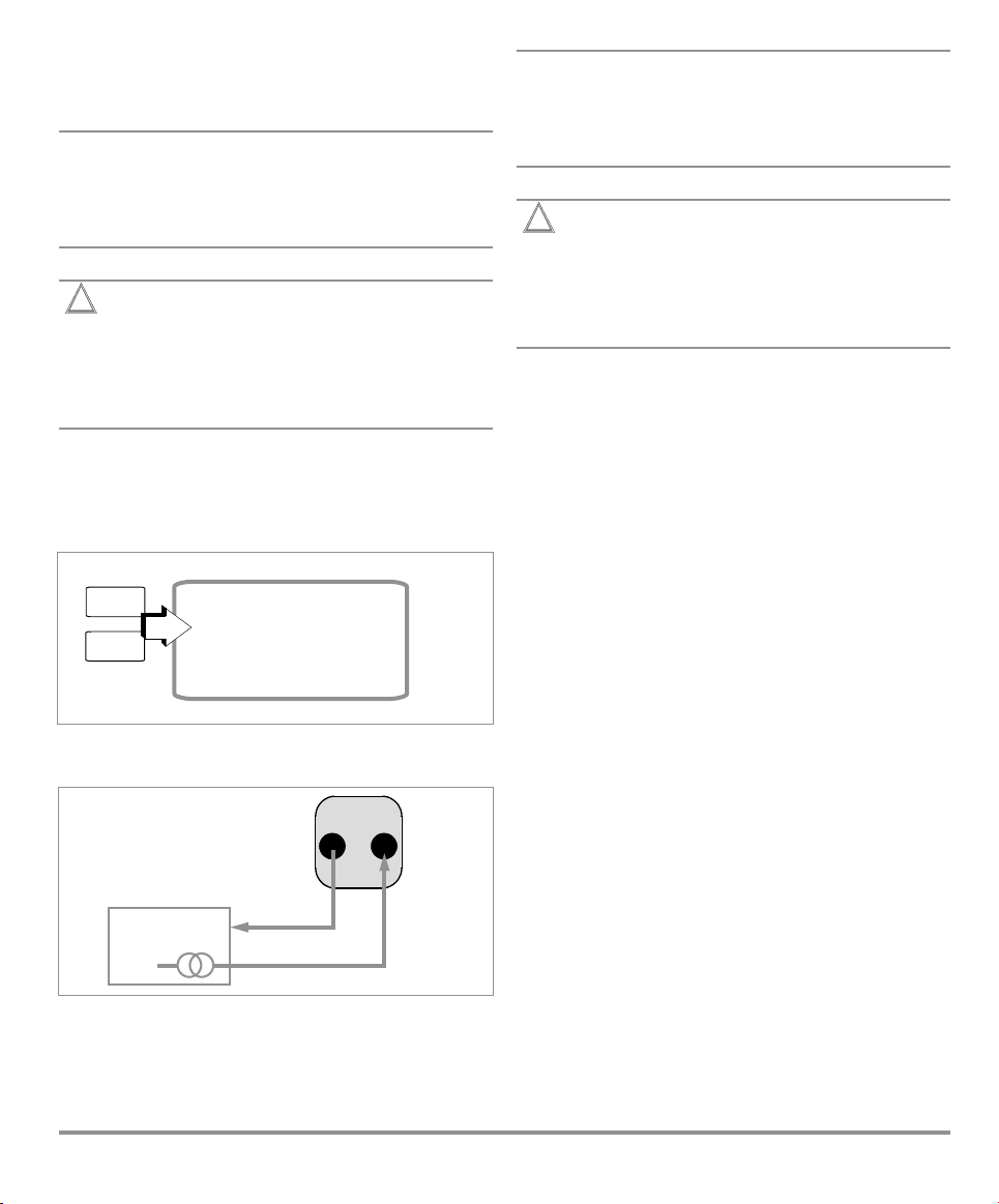
#"
$ !
Resistance
➭ Connect the DUT with the measurement cables as
shown.
2-Wire Resistance Simulator
DUT
➭ Select the Ω calibration function with the rotary switch.
➭ Setting the simulation value:
The decade (i.e. the position of the digit to be changed) is
selected with the $! keys, and the respective digit is
set with the #" keys.
GOSSEN METRAWATT GMBH 7
1454.5
–
+
NUM ON
Ω
2l
CALIBRATOR
Output
–
Input
Measuring current 50 µA ... 5 mA
+
Page 8

6 Temperature Simulation [°C]
Resistance temperature detectors (RTD) and Thermocouples
(TC) with specified external reference junction temperature
can be simulated.
➭ Select the °C calibration function with the rotary switch.
➭ Connect the DUT with the measurement cables as
shown.
➭ unit of measure °C or °F can be selected with the ESC
key.
6.1 Temperature Simulation of Resistance Temperature
Detectors – Position °C
Resistance temperature detectors are simulated by means of
resistance values.
➭ Selecting sensor type:
Press the ESC key until you proceed to the sensor selection sub-menu.
Select either type Pt100, Pt1000, Ni100 or Ni1000 with
the #" keys for the simulation of an RTD. Press the
↵ key to return to the temperature simulation value main
menu.
➭ Setting the temperature simulation value:
The decade (i.e. the position of the digit to be changed) is
selected with the $! keys, and the respective digit is
set with the #" keys. Alternatively, you can press the
#" keys at any entry position until the higher ranking digits are changed as well.
Pt100/1000
Ni100/1000
sensor
RTD
.
°C
ESC
#"
Sensor
Selection
#"
$ !
Temperature
Simulation Value
After applying the measuring current it takes a maximum of
30 ms for the calibrator output to adjust to the specified
resistance value.
Incorrect measured values may result in conjunction with
DUTs which do not have a steady measuring current (e.g.
scanned measuring inputs) if measurement has already been
started during setting time. The calibrator cannot be used for
such objects.
pt1000 sele t
↵
ESC
NUM ON
0123.2
Pt1000
2l
°C / °F
(... 4x)
°C
6.2 Temperature Simulation of Thermocouples – Position °C
Thermocouples are simulated by means of voltage. Internal
or external temperature compensation is possible.
➭ Selecting sensor type:
Press the ESC key until you proceed to the sensor selection sub-menu.
Select either type B, E, J, K, L, N, R, S, T or U with the
#" keys for the simulation of a thermocouple. Press the
↵ key to return to the temperature simulation value main
menu.
➭ Internal or external reference temperature:
Press the ↵ key until Extern appears.
Selection is made with the #" keys.
intern: Press the ↵ key to return to the temperature si-
mulation value main menu. The measured internal refernece temperature is indicated with an ’I’ for internal on
the right-hand side at the bottom of the auxiliary display.
extern: Press the ↵ key to proceed to the temperature
value sub-menu.
➭ Setting the external temperature value:
The last entry position on the right-hand side blinks.
Enter the digits with the #" keys. Press the ESC key to
move the entry cursor one digit to the left. Alternatively,
you can press the #" keys at any entry position until the
higher ranking digits are changed as well.
By pressing the ↵ key to acknowledge the entry cursor at
the last entry position on the right-hand side, you store
the new value and return to the temperature simulation
value main menu. The external reference temperature is
indicated with an ’E’ for external on the right-hand side at
the bottom of the auxiliary display.
Function Description and Applications
10 different types of thermocouples can be selected, and can
be simulated within the temperature ranges specified
by IEC/DIN.
Selection can be made between an internally measured reference junction temperature, or numeric entry of an external
reference junction temperature within a range of –30 to
+40 °C.
Important Notes Regarding the Reference Temperature
The internal reference temperature is measured continuously
with the help of an integrated temperature sensor.
The reference temperature is generally measured at the thermocouple connector jack for devices under test with a thermocouple measuring input.
The two measurements may yield different results, and differences are registered as errors during thermocouple simulation. The following methods help to reduce this error:
a) The device under test is connected to the jacks at the
calibrator with equalizing leads for the thermocouple to
be simulated.
b) The temperature of the thermocouple connector jack at
the device under test is measured with a precision temperature measuring instrument, and the resulting value is
.
TC
8 GOSSEN METRAWATT GMBH
Page 9

entered to t
brator and the device under test are connected with copper
wire.
Otherwise, the external reference temperature is entered in all
cases where temperature measurement at the device under
test is accomplished by means of a thermostatic reference
junction (end of the thermocouple equalizing lead).
!
Example ad a) Internal Reference Junction
CALIBRATOR
–
he calibrator as a reference temperature. The cali-
Attention!
In this operating mode interference voltages must not
be applied to the calibrator jacks.
In the event of operating errors, such as the shortterm application of a high interference voltage, the instrument/calibrator is protected by a replaceable
fuse F3, see chapter 12.3.
Output
+
Equalizing Lead
Terminal Block
Selecting Sensor Type, Setting the Temperature Simulation Value
and Entering the External Reference Temperature
B, E, J, K, L
N, R, S, T, U
#"
Sensor
Selection
#"
$ !
Temperature
Simulation Value
sens0r
TC
lselet
↵
ESC
NUM
l:0120.2
TC
2L
(... 2x)
↵
E. 030.0
ESC
°C
ESC
°C / °F
(... 4x)
ON
°C
↵
#"
intern
extern
e=tern
ref
intern
temp
Device to be calibrated
Example ad b) External Reference Junction
CALIBRATOR
Output
+
–
Temperature
measurement, e.g.
via multimeter with
temperature sensor
Copper Wire
Terminal Block
Device to be calibrated
GOSSEN METRAWATT GMBH 9
#"
$ !
External
Temperature Value
↵
E:000.0
ref
temp
ESC
(... 4x)
↵
°C
Page 10

7 Current Source and Current Sink
➭ Connect the device under test with the measurement ca-
bles.
➭ Select the mA current sink calibration function or
mA current source with the rotary switch.
➭ Press Esc until you enter the range selection menu.
➭ Select the desired range:,
0 … 20 mA, 4 … 20 mA or 0 … 24 mA,
with the #" keys.
➭ Press the ↵ key to enter the output menu.
➭ Setting the simulation value:
The decade (i.e. the position of the digit to be changed) is
selected with the $ ! keys, and the respective digit is
set with the #" keys.
ON indicates that the current source is active.
7.1 Current Sink – Simulation of a 2-Wire Transmitter
A current sink (0 … 24 mA) or current loop load can be simulated with this function. The calibrator regulates the current,
which flows via the calibrator jacks from an external power
supply, independent of direct voltage applied to the jacks
(4 … 27 V). The caliibrator varies the internal resistance such
that the adjusted current value flows.
Range Selection Menu
#"
Current
Range
NUM
4-20
SINK
ON
mA
sele t range
Example of a 2-Wire Transmitter Measuring Circuit
Peripheral Device
24 V
Power
Pack
7.2 Current Source
Internal supply power is used for the simulation of a current
source.
+
–
4 ... 20 mA = 0 ... 100 °C
Range Selection Menu
#"
Current
Range
+
–
NUM
0-20
mA
SOURCE
CALIBRATOR
Output
–
ON
+
sele t range
#"
$ !
Current Value
↵
NUM ON
13.452
0-20
mA
ESC
(... 2x)
mA
SOURCE
↵
#"
$ !
Current Value
Note!
☞
The latest adjusted simulator range is stored to memory. Voltage at the calibrator jacks may not exceed
27 V in the current sink operating mode, because
thermal overload would otherwise occur and the fuse
F3 would blow.
LoVolt appears at the display where the voltage is too
low.
10 GOSSEN METRAWATT GMBH
13.452
4-20
NUM ON
mA
ESC
SINK
SINK
(... 2x)
mA
Note!
☞
The internal control circuit of the current source is
monitored: if voltage drops by more than 20 V at the
external burden or if the current circuit is interrupted,
„Hi burd“ appears at the display.
Attention!
!
In this operating mode interference voltages must not
be applied to the calibrator jacks.
In the event of operating errors, such as the shortterm application of a high interference voltage, the instrument/calibrator is protected by a replaceable
fuse F3, see chapter 12.3.
Simulation in Percentages (current source only)
➭ Select the simulation function and the output range
(Isink/Isource = 4 … 20 mA) with the rotary switch and
the # key.
➭ Press the ESC and # keys simultaneously.
Page 11

➭ Select a value for 0% (lower range limit) with the
" # keys and acknowledge with the ↵ key.
➭ Select a value for 100% (upper range limit) with the
" # keys and acknowledge with the ↵ key.
➭ The output range now includes a span of 0 to 100%, and
the unit of measure mA is displayed along with a percentage value.
➭ Exit the “percentage simulation” function by pressing the
ESC key, or by turning the rotary switch.
8 Interval Functions, Ramp Functions and Procedures
Two types of setpoint sequences can be generated in order
to simulate sensor conditions at the inputs of transducers,
transmitters and buffer amplifiers:
Interval sequences (see chapter 8.1)
Ramp sequences (see chapter 8.2)
With the help of METRAwin
procedures with up to 99 steps can be generated at the PC
in addition to the above mentioned sequences.
The following parameters must be specified to this end:
measuring function, measuring range, tolerance limits, absolute limit values, setpoints and expected values. Up to 10
procedures can be uploaded to the calibrator. The procedures are then selected by name and started on-site. Measured values saved to the procedures can be subsequently
read out with a PC.
8.1 Interval Sequences – INT Function
Output ranges are divided into rising or declining interval
steps with this function, and the number of interval steps, as
well as their duration, can be specified. Above all, this function is suited for the calibration of analog indicators and
recorders during single-handed operation.
Input parameters for interval sequences include:
• All simulator functions except for Hz can be adjusted as
output quantities.
•A lower (Start) and an upper (End) range limit can be
selected for each output quantity from within the overall
range.
• The number of steps can be set within a range of
1 … 99.9. The number of steps can be entered as a
whole number as well, which is especially practical for
analog indicators and recorders with non-standardized
scale divisions.
• The interval duration per step (t1) can be selected from
within a range of 1 second to 60 minutes.
• The sequences can be run manually or automatically.
• Step jumps can be selected manually (Auto = no) with the
" # keys, or automatically (AUT = yes) with selectable
time per step.
90-2 software as an accessory,
Examples of Interval Sequences:
Manual Interval Sequence
After configuring all parameters in accordance with the menu
flowchart on page 13 for manual interval sequence read-out
(Int, Auto = no), the individual steps can be triggered with the
" # keys.
The relationship between the output signal and each of the
key operations is depicted with the help of the following
example.
Example of a Manually Controlled Interval Sequence
I
Source
[mA]
manual stop
20
16
12
8
4
""" "
➀➂➁
"###
+
"
#
t[s]
The time intervals are only identical during
automatic operation.
Key
1 The sequence is started by pressing the ↵ key when
Int start is displayed (see Menu Flowchart on page 12).
2 The sequence is stopped by pressing the " or the #
key, and is started again in the corresponding direction
when the same key is pressed once again.
3 Stop the interval sequence by simultaneously pressing
and holding the " and the # key (2 audible acoustic signals must be generated).
GOSSEN METRAWATT GMBH 11
Page 12

Automatic Interval Sequence
Automatic execution of a programmed sequence range is
above all advisable if feeding to a signal circuit, and scanning
of the peripheral device under test are physically separated.
After configuring all parameters in accordance with the menu
flowchart on page 13 for the “automatic interval sequence”
(Int, Auto = yes), the sequence can be started, and stopped
or continued at any desired time.
Example of an Automatic Interval Sequence
U
[V]
LCD:
Interval parameters:
Start =2V, End = 10 V, number of interval steps = 3, t1 = 5 s,
auto = Yes (yes for automatic sequence)
Key
1 The sequence is started by pressing the ↵ key when Int
2 The sequence is stopped by pressing the " or the #
3 The sequence is resumed by pressing the " key, and
4 Stop the interval sequence by simultaneously pressing
run up stop
10
7,3
4.6
2
510152025
0
➀➃➁
:
start is displayed (see Menu Flowchart on page 12).
key. Interval time elapsed thus far is saved as t
remaining sequence duration t
and holding the " and the # key (2 audible acoustic signals must be generated).
run dn hold run up run dn
stop
continue
#
"
➂
Output quantity: U (0 … 15 V range),
is equal to t1 – tx.
y
+
"
#"
.
x
t[s]
Menu Flowchart: Starting and Stopping the Interval Sequence
#
+
"
2x
#"
Int
ready
↵
ESC
Int
set start
Start
sequence.
05.000
0-20 run dn
1x: Stop sequence: Display: hold (hold)
#
2x: Continue sequence: Display: run dn (run down)
1x: Stop sequence: Display: hold (hold)
"
2x: Continue sequence: Display: run
+
#
↵
INT ON
mA
"
mA
SOURCE
2x
#"
Start must
blink.
#"
Up (run up)
Stop the
interval sequence.
Int
stop
ESC during the sequence (run or hold):
ESC
12 GOSSEN METRAWATT GMBH
Return to calibration function.
ESC when stopped:
Return to sequence.
Page 13

Menu Flowchart: Interval Parameters Configuration
#"
SEt must blink:
Configure
the ramp.
#"
Output Quantity:
U, ISinc, ISour,
R or temp
+
#
#"
"
Int
ready
↵
ESC
Int
set start
↵
ESC
I sour
Int func
2x
#"
End:
Upper
Range Limit
#"
Number of
Interval Steps
#"
Interval Duration
t1 [s]
↵
ESC
20.000
Int end
↵
ESC
05.5
Int steps
↵
ESC
02:00
Int t1
mA
↵
#"
Range:
0-20
4-20
0-24
0-20
Int ran ge
↵
#"
Start:
Lower
Range Limit
GOSSEN METRAWATT GMBH 13
10.000
Int start
ESC
mA
ESC
mA
↵
ESC
auto
Int no
↵
Periodic
Sequence
YES/no
#"
Page 14

8.2 Read-Out a Periodic Ramp – RAMP Function
Ramp-type signals can be used to test dynamic performance
of devices under test, or entire measuring circuits. An example would be control loop performance with a setpoint specified via the analog setpoint input at the controller. The instrument can be used to replace costly hardware and software
for the set-up of long-term test bays with cyclical time
sequences.
Parameters for the ramps depicted below include:
• The following functions can be adjusted as output quantities:
voltage U, current sink I Sink, current source I Source,
resistance R or temperature temp.
•A lower (Start) and an upper (End) range limit can be
selected for each output quantity. For standard signals
these are always 0 … 10 V and 0/4 … 20 mA, and are
otherwise values from within the entire range.
• Rise time t1 and decline time t3 are
adjustable from 0 seconds … 60 minutes.
• Dwell time t2 at the upper and lower range limits is
adjustable from 0 seconds … 60 minutes.
• There are 2 ramp sequences:
– Once only: t1, t2, t3
– Repetitive: t1, t2, t3, t2, t1, t2, t3, …
Examples of Ramp Sequences:
Example of a Periodic Ramp Sequence
Output
End
Start
t
t1
t2
t2
t3
Manually Controlled Ramp Sequences
After configuring all parameters in accordance with the menu
flowchart on page 15, rising or declining ramps can be triggered with the " and the # keys.
The relationship between the output signal and each of the
key operations is depicted with the help of the following
example.
Example of a Manually Controlled Ramp Sequence
U
[V]
LCD:
t1 up t2 run t3 dn t3 hld t3 up t3 run t3 hld t1 dn
cont.
stop
10 V
2V
stop cont.
t1 t2 t3
#
"
t3 t2
t1
+
#"#
"
"
#
➀➁➂➃➄➅
Ramp parameters
: Output quantity: U (0 … 15 V range),
Start =2V, End = 10 V, t1 = 5 s, t2 = 8 s, t3 = 5 s,
repeat = Yes (yes for periodic ramp)
Key
1 The sequence is started by pressing the ↵ key when ramp
start is displayed (see Menu Flowchart on page 16).
2 Stop the declining ramp within decline time t3 with the "
or the # key.
3 Start a rising ramp within remaining decline time t3 with
the " key.
4 Stop the ramp sequence with the " or the # key.
5 Start a declining ramp with the # key, remaining dwell
time t2 is deleted.
6 Stop the ramp sequence by simultaneously pressing and
holding the " and the # keys (2 audible acoustic signals
must be generated).
14 GOSSEN METRAWATT GMBH
Page 15

Menu Flowchart: Ramp Parameters Configuration
#"
SEt must blink:
Configure
ramp.
#"
Output Quantity:
U, ISinc, ISour,
R or temp
+
#
#"
"
ramp
ready
↵
ESC
ramp
set start
↵
ESC
I sour
ramp func
2x
#"
End:
Upper
Range Limit
#"
Rise Time t1
#"
Dwell Time t2
↵
ESC
20.000
ramp end
↵
ESC
00:05
ramp t1
↵
ESC
02:00
ramp t2
mA
↵
#"
Range:
0-20
4-20
0-24
0-20
ramp range
↵
#"
Start:
Lower
Range Limit
GOSSEN METRAWATT GMBH 15
10.000
ramp start
ESC
ESC
mA
mA
#"
Decline Time t3
↵
↵
ESC
00:28
ramp t3
↵
ESC
repeat
ramp yes
Periodic
Ramp:
YES/no
#"
Page 16

Menu Flowchart: Starting and Stopping the Ramp Sequence
#
+
"
2x
#"
ramp
ready
↵
ESC
ramp
set start
Start
sequence.
↵
05.000
0-20 t2 ru n
Stop sequence: Display: ho (Hold)
mA
Continue sequence: Display: up (up for rising slope)
RAMP ON
mA
SOURCE
dn (down for declining slope)
run (run fur sequence dwell time)
#"
Start must
blink.
#"
9 Using the Menus – from the Initial InFO Menu to
Operating Parameters
Menu-driven operation via the initial InFO menu allows the
user to query online help and configure device parameters.
➭ The initial InFO menu is accessed by simultaneously
pressing and holding the ESC| FUNC and ON | OFF keys with
the instrument switched on until “InFO” appears at the
display.
➭ The display can be switched from the main “info” menu
to the other main “set” menu, and back to the “info”
menu by pressing the #" keys.
➭ After accessing the desired main menu, the associated
sub-menus are opened by activating the ↵ key.
➭ The desired parameter is selected by repeatedly pressing
the #" keys.
➭ Acknowledge with the ↵ key in order to change the cor-
responding parameter or parameters.
➭ After the desired digit has been selected with the $ !
keys and the value has been adjusted with the #" keys,
the next digit is accessed with the ↵ key, or the display is
returned to the start menu or switched to the next sub-
menu.
➭ The calibration mode is started by repeatedly pressing
the ESC key until the simulator display appears.
➭ The calibrator is switched off by pressing and holding the
ON|OFF key until the display goes blank.
The following pages include an overview of the menu structure.
#
+
"
2x
Stop the
ramp sequence.
ramp
stop
ESC during the sequence (run or hold):
ESC
16 GOSSEN METRAWATT GMBH
Return to measuring or calibration function.
ESC when stopped:
Return to sequence.
Page 17

Main Menus and Sub-Menus
+
ESC ON
info
#"
set
2x
Query Information
↵
ESC
Battery Charge
Level
3.1
batt
" #"
V
12:45:30
27 .08 .01 time
Current
Time and Date
27.08.01
caldat
Calibration Date
V
ESC
set
set
tIme
"
addr
↵
↵
ESC
↵
↵
ESC
Set Time
$ !
15:50:05
set t Ime
Possible Settings (hh:mm:ss, hh=hour, mm=minute, ss=second)
Set Date
20.11.01
set date
Possible Settings (TT:MM:JJ, TT=day, MM=month, JJ=year)
Set Device Address
15
set addr
Possible Setting Values (see also chapter 9.2): 0 … 15
Select
Position.
Digit
blinks
$ !
Select
Position
#"
Change
Value
#"
Change
Value
Change
Value
#"
Acknowledge
Entry
↵
Acknowledge
Address
↵
Acknowledge
Entry
↵
set
GOSSEN METRAWATT GMBH 17
Page 18

9.1 Activating the Default Values
Previously entered changes can be undone, and the default
settings can be reactivated. This may be advisable under the
following circumstances:
• After the occurrence of software or hardware errors
• If you are under the impression that the calibrator does
not work correctly
➭ Simultaneously press and hold the ESC, # and " keys,
and switch the instrument on with the ON |OFF key.
9.2 Transmission Mode Operation with RS 232 Interface
The calibrator is equipped with a bidirectional infrared interface for communication with a PC. The commands are optically transferred through the calibrator housing by means of
infrared light to an interface adapter (accessory), which is
attached to the calibrator. The adapter’s RS 232 interface
allows for the establishment of a connection to the PC via an
interface cable.
Commands and parameters can be transmitted from the PC
to the calibrator. The following functions can be executed:
• Configuration and read-out of calibration parameters
• Calibration function and calibration range selection
• Start calibration
• Programming of user-specific procedures
Configuring Interface Parameters
Addr – Address
If several instruments are connected to the PC via interface
adapters, each device must be assigned its own address.
Address 1 should be used for the first device address, 2 for
the second etc. If only one calibrator is used, an address
between 1 and 14 should be selected.
Address 15 is not used for addressing, i.e. the device with
address 15 always responds, regardless of the actual
address.
Switching the Interface On via PC
After transmission of a data frame from the PC, the simulator
is switched on.
For this reason, the plug type mains supply should be used
for long operational periods. This avoids automatic deactivation by the battery monitoring circuit.
Operating Controls in REMOTE Operation
When set to REMOTE operation, the instrument reacts like in
local control operation. The instrument is put back into local
control operation after switching it off and on again with the
ON| OFF key.
LC Display in REMOTE Operation
The commands transmitted by the PC during direct operation
will be executed by the instrument directly, provided the basic
function set by the message complies with the one set on the
rotary switch. The LC display will acknowledge the programmed signal value and the output type after each message.
Incorrect settings of the rotary switch are signalled by a flashing display of the scheduled basic function. The new command will be executed immediately when the rotary switch
has been set to the scheduled basic function.
Interface parameters are as follows:
Format: 8 data bits, no parity, 1 stop bit
Baud rate: 9600 baud
Signal LED on the Interface Adapter
One green and one red signal diode on the interface adapter
give you the following information and warnings:
• Green LED:
Lights up briefly when commands are transmitted from
the PC to the calibrator.
• Red LED:
Lights up during the transmission of messages from the
calibrator to the PC. This occurs each time the calibrator
is switched on and when a message received from the
PC is acknowledged. This response, as well as an
acousting signal, are generated to confirm the correct
physical communication between PC and calibrator.
18 GOSSEN METRAWATT GMBH
Page 19

10 Accessories
Interface adapters BD232 (without memory), in combination with
calibration software METRAwin
90-2, allow for remote con-
trol of the instrument by PC.
USB-HIT Interface Adapter
Alternatively, the METRA HIT28c light can also be con-
nected to the USB interface of a PC via an USB-HIT adapter.
The driver to be installed allocates a virtual COM interface to
the instrument.
A 2x series multimeter which can be optionally embedded in
a calibration system can be connected via another USB-HIT
adapter with a second USB interface at the PC.
Software METRAwin
90-2
This software allows for paperless documentation and management of calibration results, the creation of calibration procedures and remote control of the calibrator.
METRA HIT28c light sequence controls can be implemented online, or off-line after downloading complete calibration procedures.
The following conditions must be fulfilled in order to allow for
use of METRAwin
90-2:
Hardware Requirements
– WINDOWS and IBM compatible PC with at least
a 200 MHz Pentium CPU and 64 MB main memory
– SVGA monitor with a minimum of
800 x 600 pixels
– Hard disk with at least 40 MB free memory
– 3½" floppy disk drive for 1.4 MB floppies
– MICROSOFT compatible mouse
– if you want to print your data, a WINDOWS compatible
printer.
– 1 free serial COM interface for utilizing BD232
or
– 1 USB interface for utilizing USB-HIT
Software Requirements
➭ WINDOWS 95, 98, ME, NT4.0, 2000 or XP
GOSSEN METRAWATT GMBH 19
Page 20

11 Characteristic Values
max
> 30 mA
Resolution
30000
Digits
(4¾ places)
1 µA 20 V 0.05 + 20 … 20 mA
1 µAVin = 4 ... 27 V 0.05 + 2 27 V0 … 20 mA
max/Umax
With Load of Intrinsic Error
±(% of s. + Hz) I
0 … 27 V.
ext
±(% of s. + µA)
±(% of s. +
±(% of s. +
Impedance
[mA]
.
µA)
Ω)
Over-
load
18 mA
U
Simulator
Range
Calibration
Function
Direct Voltage Simulator ±(% of s. + mV) I
0…±300 mV 0.01 mV 700 Ω 0.05 + 0.02
0 … 3 V 0.1 mV 1000 Ω 0.05 + 0.2
V
0 … 10 V 1 mV 1000 Ω 0.05 + 2
0 … 15 V 1 mV 1000 Ω 0.05 + 2
Pulse / Frequency Generator
Keying ratio (mark-to-space ratio):
50%, amplitude: 10 mV … 15 V
Hz 1 Hz …1 kHz 0,1 …8 Hz1)1000 Ω 0,05 + 0,2 18 mA
Current Source Max. Load
4 … 20 mA
mA
0 … 24 mA
Current Sink
4 … 20 mA
mA
0 … 24 mA
Resistance-Type Sensor Sensor Current
Ω 5…2000 Ω 0.1 Ω 0.05...0.1..4...5 0.05 + 0.2 5 mA
1)
Frequencies of over 29 Hz can only be selected at limited intervals.
2)
Shut off when I
Note!
☞
Observe maximum allowable voltage for connection
from external sources to the calibrator output in the
event of a current sink: U
In the event of operating errors, such as the shortterm application of a high interference voltage, the
calibrator is protected by a replaceable fuse F3, this
means that the F3 fuse may be tripped in the event of
an overload > I
Simulator for Temperature Sensors (Resolution: 0.1 K)
Sensor Type Simulator
max
2)
max
max
I
max
Resistance Thermometer per IEC 751 ±(% of s.+K) I
Pt100 –200 …+ 850 – 328…+ 1562 0.1 + 0.5
Pt1000 –200 …+300 –328 …+572 0.1 + 0.2
Resistance Thermometer per DIN 43760 ±(% of s.+K) I
Ni100 –60…+ 180 –76…+356 0.1 + 0.5
Ni1000 –60…+ 180 –76 …+ 356 0.1 + 0.2
RTD Sensor Current: 0.05 ... 0,1 ... 4
Thermocouples per DIN and IEC 584-1 ±(% of s.+K)
K (NiCr/Ni)
°C / °F
J (Fe/CuNi)
T (Cu/CuNi) –270…+400 – 454…+ 752
B (Pt30Rh/Pt6Rh) +500...+1820 +932…+3308
E (NiCr/CuNi)
R (Pt13Rh/Pt) –50…+1768 –58…+ 3214
N (CU/Cu10)
S (Pt10Rh/Pt) –50…+1768 –58…+ 3214
J (Fe/CuNi) – 200…+900 – 328…+1652
U (Cu/CuNi) –200…+ 600 –328…+ 1112
* Without internal reference junction
** Relative to fixed reference temperature in °C and thermovoltage of the
thermocouple, for additional error see also table on page 21.
Reference junction, internal: 2 K intrinsic error
Reference junction, external: entry of –30 … 40 °C
Range
in °C
–250…+1372
–210…+1200
–270…+1000
–270…+1300
Simulator
Range
in °F
... 5 mA
–418…+2501
–346…+ 2192
–454…+1832
–454…+2372
Key
s. = setting
d = digit
Real-Time Clock
Accuracy ±1 minute per month
Temperature Influence 50 ppm/K
Reference Conditions
Ambient
Temperature + 23 °C ±2K
Relative Humidity 40 ... 60%
Battery Voltage 4.5 V ±0.1 V
Intrinsic
Error
*
**
0.1 + 0.5 18 mA
Overload
max
5 mA
max
5 mA
I
max
20 GOSSEN METRAWATT GMBH
Page 21

Thermocouple Simulation Error in [°C]
Thermocouple error is specified in the technical data as thermovoltage error: ∆U. ∆T error is dependent upon characteristic thermocouple slope.
In consideration of characteristic thermocouple non-linearity,
which also applies to slope (1
st
dT/dU derivation), mathemat-
ically calculated ∆T error is shown in the following table for all
thermocouple types in the 100 °C sub-range. The values
shown in the table represent maximum possible error for the
respective sub-range.
All specified error values are increased by 2 K if an internal reference temperature is used.
If an external reference temperature other than 0 °C is used,
the sub-range values in the table are adjusted by the amount
of the reference temperature.
Example
Ref. temp. external = 50 °C
Sub-range 100 … 200 °C becomes 150 … 250 °C
For display in °F: numeric values in °F are increased by a factor
of 1.8.
The °F sub-ranges are calculated as follows:
°F = 32 + °C x 1.8
Additional Error for Thermocouple Simulation
Thermocouple
Typ e
Sub-Range °CJ L T U K E S R B N
– 200 ...– 100
– 100 ... 0
0 ... 100
100 ... 200
200 ... 300
300 ... 400
400 ... 500
500 ... 600
600 ... 700
700 ... 800
800 ... 900
900 ... 1000
1000 ... 1100
1100 ... 1200
1200 ... 1300
1300 ... 1400
1400 ... 1500
1500 ... 1600
1600 ... 1700
1700 ... 1800
T Error in K for Thermocouple Types at Ref. Temp. 0°C
1.17 0.83 1.52 1.2 1.59 1.03 2.38
≥
-50°
≥
0.55 0.56 0.78 0.77 0.73 0.51
0.42 0.41 0.52 0.51 0.53 0.35 3.77 3.92 0.77
0.46 0.45 0.47 0.49 0.6 0.36 2.78 2.75 0.73
0.51 0.51 0.47 0.46 0.63 0.39 2.47 2.36 0.7
0.56 0.56 0.49 0.49 0.67 0.43 2.31 2.19 0.71
0.6 0.6 0.51 0.71 0.48 2.28 2.09 0.74
0.63 0.62 0.76 0.53 2.24 2.06 4.12 0.78
0.64 0.63 0.82 0.58 2.23 2.02 3.54 0.82
0.66 0.64 0.89 0.64 2.21 1.99 3.12 0.87
0.73 0.66 0.96 0.71 2.18 1.95 2.84 0.93
0.83 1.04 0.77 2.16 1.93 2.62 0.99
0.9 1.12 2.16 1.91 2.46 1.05
0.96 1.22 2.17 1.92 2.34 1.13
1.32 2.2 1.94 2.27 1.21
≤
1370
°C:
1.39
-50°
4.79
5.29
2.24 1.99 2.22
2.31 2.04 2.19
2.39 2.12 2.2
2.52 2.23 2.24
≤
≤
1760
1760
°C:
°C:
2.76
2.42
2.33
1.03
GOSSEN METRAWATT GMBH 21
Page 22

Display
LCD panel (65 mm x 30 mm) with display of up to 3 values,
the respective units of measure and various special functions.
Display / Char. Height 7-segment characters
Main display: 12 mm
Auxiliary displays: 7 mm
Polarity Display “–” sign is displayed in the range
–300 mV
LCD Test All display segments available dur-
ing operation are activated after the
instrument is switched on.
Power Supply
Batteries 3 ea. 1.5 V mignon cell
alkaline manganese per IEC LR6 or
equivalent rechargeable batteries.
If rechargeable batteries are used,
they must be charged externally.
Service Life With alkaline manganese
(2200 mAh)
Calibration
Function
mV, thermocouple 48 mA 40 h
15 V 85 mA 20 h
Ω, RTD 95 mA 18 h
Sink, 20 mA 175 mA 10 h
Source, 20 mA 140 mA 12 h
Service Life
If voltage drops below 2.7 V, the
instrument is switched off automatically.
Battery Test “ ” is displayed automatically if
battery voltage drops to below
approx. 3.5 V.
Mains Power When mains power pack NA5/600
is connected, the power supply
comes from the mains power pack;
battery power is not consumed;
there is no risk of batteries being
charged.
Fuse Calibrator F3
Position of fuse see chapter 12.3
M125mA/250V, 5 mm x 20 mm
1.5 kA switching capacity at 250 V
AC and ohmic load
Electrical Safety
Safety Class II per EN 61010-1:2001/
VDE 0411-1:2002
Operating Voltage max. 50 V
Contamination Factor 2
Test Voltage 500 V~ per EN 61010-1:2001/
VDE 0411-1:2002
Electromagnetic Compatibility (EMC)
Interference emission EN 61 326: 2002 class B
Interference immunity
EN 61326: 2002
IEC 61000-4-2: Feature A:
8 kV atmospheric discharge
4 kV contact discharge
IEC 61000-4-3: Feature B:
3V/m
Data Interface
Data Transmission optical via infrared light through the
housing
with interface adapter as accessory
Type RS 232C, serial, per DIN 19241
Bidirectional baud rate (read and write)
(MM ↔ PC)
BD232, USB-HIT: 9600 baud
Ambient Conditions
Accuracy Range 0 °C ... +40 °C
Operating Temperature −10 °C ... + 50 °C
Storage Temperature − 25 °C ... + 70 °C
(without batteries)
Relative Humidity 40% ... 75%,
no condensation allowed
Elevation to 2000 m
Deployment indoors,
outdoors: only in the specified
ambient conditions
Mechanical Design
Dimensions 84 mm x 195 mm x 35 mm
Weight approx. 420 g with batteries
Protection IP 50
Extract from table on the significance of IP codes
IP XY
(1st digit X)
Protection against
foreign object entry
0 not protected 0 not protected
1 ≥ 50.0 mm
2 ≥ 12.5 mm
3 ≥ 2.5 mm
4 ≥ 1.0 mm
5 dust protected 5 water jets
∅
∅
∅
∅
IP XY
(2nd digit Y)
Protection against the
penetration of water
1 vertically falling drops
2 vertically falling drops
with enclosure tilted 15°
3spraying water
4 splashing water
22 GOSSEN METRAWATT GMBH
Page 23

12 Maintenance
Attention!
!
Disconnect the instrument from the measuring circuit
before opening to replace batteries or fuses!
12.1 Battery
Note!
☞
Removing the Battery During Periods of Non-Use
The integrated quartz movement draws power from
the battery, even when the calibrator is switched off.
It is advisable to remove the battery during long periods of non-use for this reason (e.g. vacation). This
prevents excessive depletion of the battery, which
may result in damage under unfavorable conditions.
The current battery charge level can be queried in the “Info”
menu: ESC| FUNC + On #" inFo ↵ X.X V (bAtt).
Make sure that no battery leakage has occurred before initial
start-up, and after long periods of storage. Continue to
inspect the batteries for leakage at short, regular intervals.
If battery leakage has occurred, carefully and completely
clean the electrolyte from the instrument with a damp cloth,
and replace the batteries before using the instrument.
If the “ ” symbol appears at the display, the batteries should
be replaced as soon as possible.
The instrument requires three 1.5 V batteries in accordance
with IEC R 6 or IEC LR 6, or equivalent rechargeable batteries.
➭ Important for reassembly: First set the housing base onto
the housing top and align accurately (see photo below).
Then press the two housing halves together, first at the
bottom front (a), and then at the top front (b).
(b) (a)
➭ Secure the housing base with the two screws.
➭ Please dispose of depleted batteries in accordance with
environmental protection regulations!
12.2 Power Pack
Use only the NA5/600 power pack from GOSSEN METRAWATT GMBH in combination with your instrument. This
assures operator safety by means of an extremely well insulated cable, and safe electrical isolation (nominal secondary
ratings: 5 V/600 mA). Installed batteries are disconnected
electronically if the power pack is used, and need not be
removed from the instrument.
Country Type / Article Number
Germany Z218F
Replacing the Batteries
➭ Set the instrument face down onto a flat working surface,
loosen the two screws at the back and lift off the housing
base, starting at the bottom. The housing top and housing bottom are held together with the help of snap hooks
at the top front.
➭ Remove the batteries from the battery compartment.
➭ Insert three 1.5 V mignon cells into the battery compart-
ment, making sure that the plus and minus poles match
up with the provided polarity symbols.
GOSSEN METRAWATT GMBH 23
Page 24

12.3 Fuses
Replacing the Fuses
➭ Open the instrument as described under „Replacing the
Batteries“, see chapter 12.1.
➭ Remove the blown fuse with the help of an object such
as a test probe, and replace it with a new fuse.
Attention!
!
Use specified fuse only!
If a fuse with other tripping characteristics, other current ratings or other switching capacities is used, the
operator is placed in danger, and protective diodes,
resistors and other components may be damaged.
The use of repaired fuses or short-circuiting the battery holder is prohibited.
Location of fuses
Indication of
fuse characteristics
(see also Technical
Characteristics, page 22
F3
13 Calibrator Messages
The following messages appear at the main or the auxiliary
displays as required. See “Symbols used in the Digital Display” on page 2 for messages displayed via fixed display segments.
Message Function Significance
hiCurr
loCurr
0ut0l
lovolt
hiBurd
Simulate voltage/
Impulse
Simulate resistance/RTD
Resistance
simulator
Voltage simulator
Pulse and
frequency generator
Current sink U < 3 V
Current source High burd = high burden, the voltage applied
Blinking Unit of Measure
All calibration functions are balanced/adjusted in accordance
with technical specifications at the factory for each series
METRA HIT28c light calibrator. If a unit of measure blinks,
this indicates that the balancing constant which has been
established and saved to the calibrator is no longer available
for the respective function. If this is the case, results may
deviate from the specification. We recommend sending the
instrument to our Repair and Replacement Parts department
for rebalancing (see chapter 14).
High current = current too high (I > 18 mA)
High current = current too high (I > 4.5 mA)
Low current = current too low (I < 40 µA)
Indicates that connector jacks are open
(e.g. with Pt and Ni sensors) or polarity reversal
Out of limit = limit value violated (I > 30 mA),
3 acoustic signals are generated at the same
time and the simulator jacks are deactivated.
After eliminaing the cause of the overload, the
output can be reactivated with the ON| OFF key.
(insufficient loop impedance)
by the connected circuit is too high. The resulting voltage at the calibrator exceeds or is equal
to 20 V
12.4 Housing
No special maintenance is required for the housing. Keep
outside surfaces clean. Use a slightly dampened cloth for
cleaning. Avoid the use of cleansers, abrasives and solvents.
24 GOSSEN METRAWATT GMBH
Page 25

14 Repair and Replacement Parts Service
DKD Calibration Lab *
and Rental Instrument Service
When you need service, please contact:
GOSSEN METRAWATT GMBH
Service Center
Thomas-Mann-Strasse 20
90471 Nürnberg • Germany
Phone +49-(0)-911-8602-0
Fax +49-(0)-911-8602-253
E-Mail service@gossenmetrawatt.com
This address is only valid in Germany.
Please contact our representatives or subsidiaries for service
in other countries.
* Calibration Laboratory
Competent Partner
GOSSEN METRAWATT GMBH is certified in accordance with
DIN EN ISO 9001:2000.
Our DKD calibration laboratory is accredited by the Physikalisch Technische Bundesanstalt (German Federal Institute
of Physics and Metrology) and the Deutscher Kalibrierdienst
(German Calibration Service) in accordance with DIN EN ISO/
IEC 17025 by under registration number DKD–K–19701.
We offer a complete range of expertise in the field of metrology: from test reports and proprietary calibration certificates right
on up to DKD calibration certificates.
Our spectrum of offerings is rounded out with free test equip-
ment management.
An on-site DKD calibration station is an integral part of our service department. If errors are discovered during calibration,
our specialized personnel are capable of completing repairs
using original replacement parts.
As a full service calibration laboratory, we can calibrate instruments from other manufacturers as well.
for Electrical Quantities DKD– K – 19701
accredited per DIN EN ISO/IEC 17025
Accredited measured quantities: direct voltage, direct current
values, DC resistance, alternating voltage, alternating current values,
AC active power, AC apparent power, DC power, capacitance and
frequency
15 Warranty
The warranty period for all measuring and calibration instruments of the METRA HIT series is 3 years from delivery.
A warranty period of 12 months is granted for calibration.
Warranty covers defective material and workmanship, not
including any damage caused by inappropriate use or operating errors as well as any follow-up costs.
16 Product Support
When you need support, please contact:
GOSSEN METRAWATT GMBH
Product Support Hotline
Phone +49-(0)-911-8602-112
Fax +49-(0)-911-8602-709
E-Mail support@gossenmetrawatt.com
DKD Calibration Certificate Reprints
If you order a DKD calibration certificate reprint for your
instrument, please provide us with the reference numbers
indicated in the upper and lower most fields of the calibration
seal. We do not need the instrument’s serial number.
GOSSEN METRAWATT GMBH 25
Page 26

Edited in Germany • Subject to change without notice • A pdf version is available on the Internet
GOSSEN METRAWATT GMBH
Thomas-Mann-Str. 16-20
90471 Nürnberg •
Germany
Phone +49-(0)-911-8602-0
Fax +49-(0)-911-8602-669
E-Mail info@gossenmetrawatt.com
www.gossenmetrawatt.com
 Loading...