

Page 1
Operating Instructions
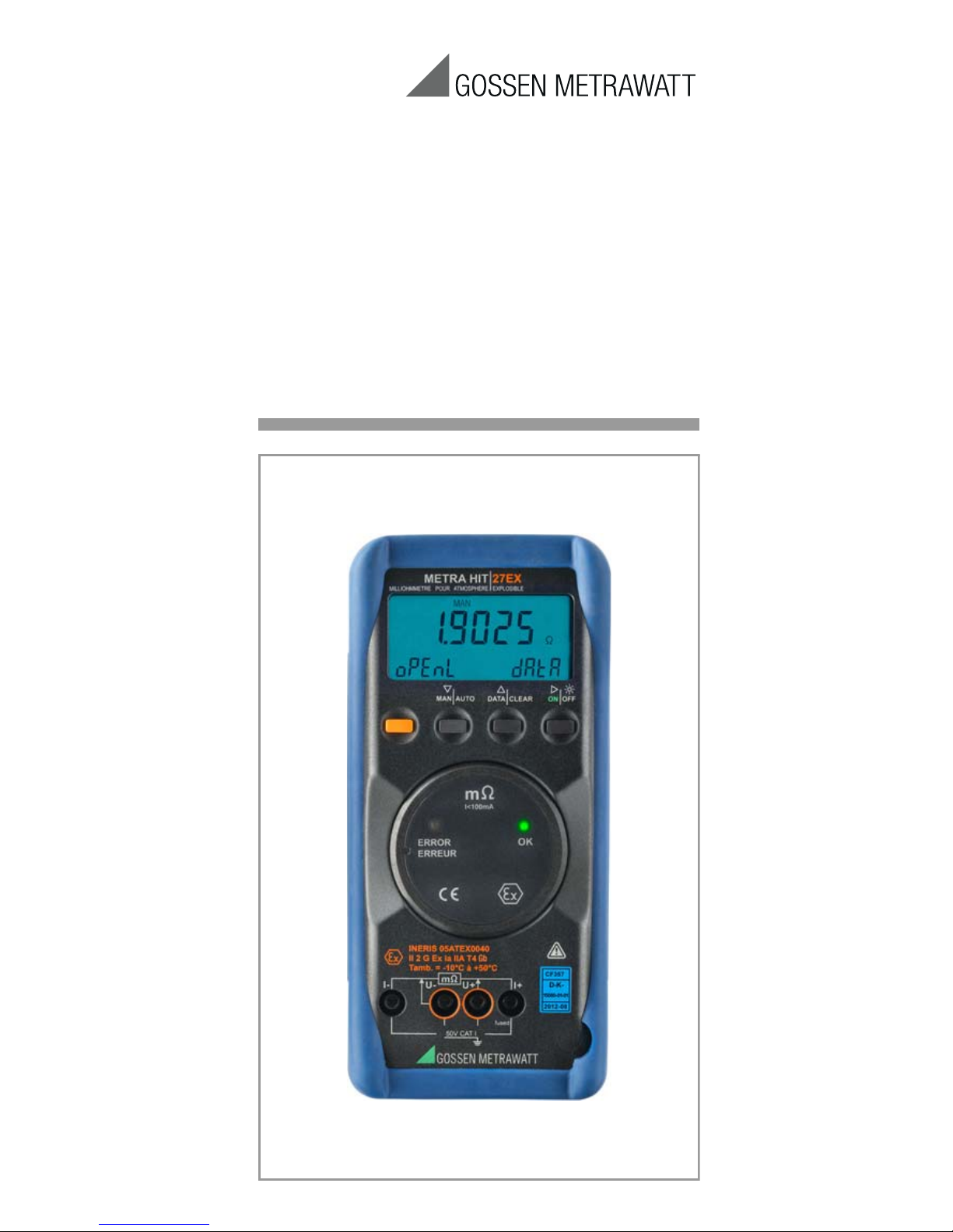
METRA HIT⏐27EX
Milliohmmeter for deployment
in potentially explosive atmospheres
3-349-336-49
9/8.16
Page 2
2 GMC-I Messtechnik GmbH
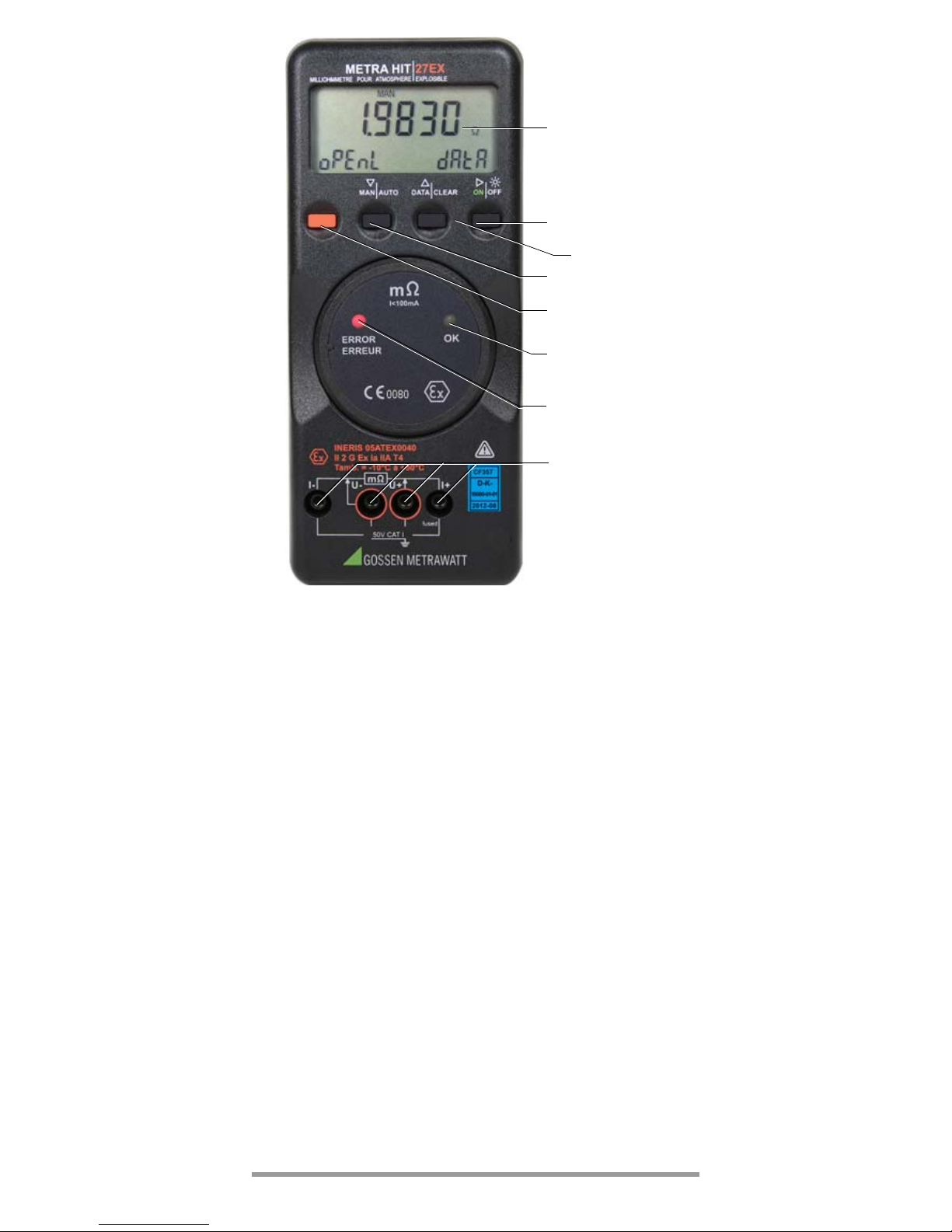
1Display (LCD)
2ON|OFF key for ON / OFF
(ON short: instrument ON → ON short: background illumination ON →
→
OFF short: background illumination OFF → OFF long: instrument OFF)
Operating mode menu: open submenus / acknowledge entries
3 DATA|CLEAR key for the functions save/delete measured value
Operating mode menu: Selection of individual menu items
against direction of flow,
increase values
4 MAN|AUTO key for manual measuring range selection
Operating mode menu: Selection of individual menu items
in direction of flow
decrease values
5 MENU/ESC
Operating mode menu: Exit menu level and
return to a higher level,
exit parameters configuration
without saving data
6LED OK blinks: valid measured value
7LED ERROR blinks: incorrect connection
8 Connector jacks *
1
2
6
4
5
8
Measurement only on
voltage-free objects!
→ chapter 5
→ chapter 3
→ chapter 4
→ chapter 7.2
→ chapter 7.3
→ chapter 7
7
→ chapter 7.3
3
→ chapter 6
Page 3
GMC-I Messtechnik GmbH 3
GB
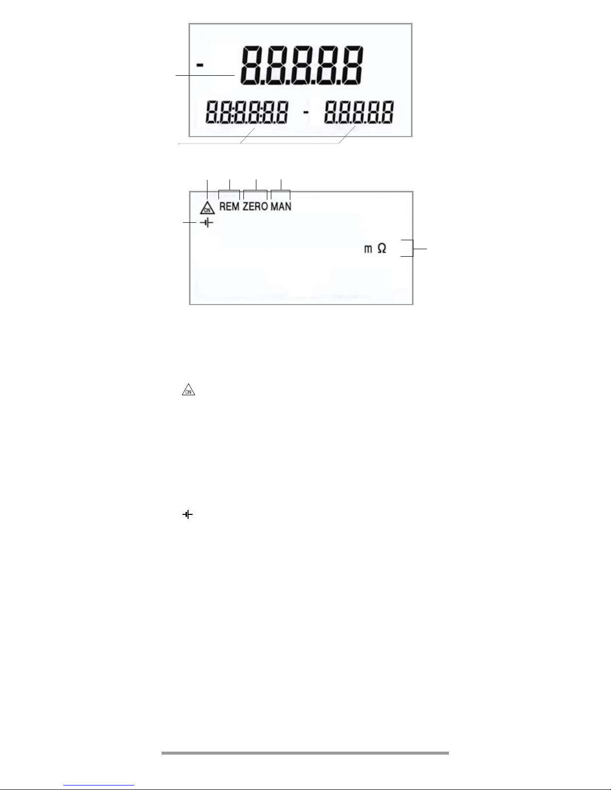
Symbols used in the Digital Display
1 Main display with decimal point
2 Auxiliary displays
3 : Milliohmmeter in continuous operation,
ON blinks at transmission frequency in transmission mode
4 REM: Memory mode operation, disappears after communication
via the interface is ended by means of key or switch
operation
5 ZERO: Zero balancing
6 MAN: Manual measuring range selection
7 Unit of measure (if blinking, refer to chapter 11 on page 33)
8 : Low battery voltage, replace batteries
* I- Measurement input
U- Sense – for 4-wire measurement
U+ Sense + for 4-wire measurement
I+ mΩ; Ω measurement input
1
2
8
64 53
7
Page 4

4 GMC-I Messtechnik GmbH
Contents Page
1 Application .............................................................. 5
2 Safety Features and Precautions ............................ 5
3 Initial Start-Up ......................................................... 8
4 Selecting Measuring Functions and Measuring Ranges .10
4.1 Automatic Measuring Range Selection ................................10
4.2 Manual Measuring Range Selection ....................................10
4.3 Quick Measurements .........................................................10
5 Triple Digital Display ............................................. 11
6 Measured Value Storage ....................................... 12
6.1 Measured Value Storage – Key Function “DATA” .................12
7 Milliohm Measurement (4-Pole-Measurement) .... 14
7.1 Compensation of Cable Resistance .....................................14
7.1.1 Measurement with Kelvin Probe KC27 ................................ 14
7.2 Thermovoltage Compensation ............................................. 15
7.3 Milliohm Measurement with ≤ 100 mA DC [mΩ] .................16
8 Using the Menus – from the Initial InFO Menu to
Operating and Measuring Parameters .................. 17
8.1 Sampling rAtE ........................................................ 17
8.2 Saving Measured Values ....................................................18
8.2.1 Memory Mode – DATA Key Function (see also chapter 6.1) ..18
8.2.2 Memory Mode Operation – STORE Menu Function ............... 19
8.3 Querying Memory Occupancy – INFO MEMO/OCCUP ....... 19
8.4 Clearing the Memory – MEMO CLEAr .............................20
8.5 Activating the Default Values ..............................................20
8.6 Transmission Mode Operation with RS 232 or USB Interface 21
9 Characteristic Values ........................................... 26
10 Maintenance ......................................................... 30
10.1 Batteries ............................................................................30
10.2 Fuses ................................................................................31
10.3 Housing and Display ........................................................... 32
10.4 Collection of Used Instruments and Environmentally
Compatible Disposal ........................................................... 33
11 System Messages ................................................. 33
12 Repair and Replacement Parts Service,
Calibration Center and Rental Instrument Service 34
13 Manufacturer’s Guarantee .................................... 35
14 Product Support .................................................... 35
15 Recalibration ......................................................... 36
Page 5

GMC-I Messtechnik GmbH 5
GB
1 Application
METRA HIT⏐ 27EX is a milliohmmeter with 4-pole measurement, which is designed for deployment in potentially
explosive environment.
In accordance with directive 2014/34/EU the device is
approved for being used in explosive, gaseous atmospheres (IIA T4) with ambient temperatures between –
10 °C and +50 °C.
The device conforms to the following standards:
– EN 60079-0:2012 + A11:2013
– EN 60079-11:2012
It bears CE certification number, type INERIS 05ATEX0040,
which has been conferred by the Ineris certification authority.
2 Safety Features and Precautions
You have selected an instrument which provides you with
high levels of safety.
This instrument fulfills the requirements of the applicable
EU guidelines and national regulations. We confirm this
with the CE marking. The relevant declaration of conformity
can be obtained from GMC-I Messtechnik GmbH.
The METRA HIT⏐27EX is manufactured and tested in
accordance with safety regulations IEC 61010–1:2010 /
EN 61 010–1:2011/VDE 0411–1:2011/EN 60079-0:2009
and
EN 60079-0:2012/EN 60079-11:2012. When used for its
intended purpose, safety of the operator, as well as that of
the instrument, is assured. Their safety is however not
guaranteed, if the instrument is used improperly or handled
carelessly.
In order to maintain flawless technical safety conditions, and to
assure safe use, it is imperative that you read the operating
instructions thoroughly and carefully before placing your instrument into service, and that you follow all instructions contained
therein.
Use for Intended Purpose:
– The milliohmmeter described herein is a portable
instrument which can be held in one hand during measurements.
– The milliohmmeter may only be operated with the
included or with type-tested batteries, as specified in
the Characteristic Values.
– The milliohmmeter may only be operated with closed
housing. The instrument must be removed from the
potentially explosive environment before opening the
housing to replace batteries or fuses.
– Only the type-tested fuses specified in the Characteris-
tic Values may be used.
– The milliohmmeter may only be used to perform such
measurements as described in chapter 7.
– The limits of the overload capacity may not be
exceeded. Refer to the “Characteristic Values” on
page 26 for overload values and overload duration.
Page 6

6 GMC-I Messtechnik GmbH
– Measurements may only be performed within the indi-
cated ambient conditions. See page 29 for operating
temperature range and relative humidity.
– The instrument may not be used in a dusty atmo-
sphere.
– No maintenance operation may be performed in
potentially explosive atmospheres (cleaning, replacement of batteries, opening the device, etc.)
Observe the following safety precautions:
• Type-tested Housing
The milliohmmeter may not be operated with open
housing.
In a potentially explosive atmosphere the housing may
not be opened. In this case, there is no protection
against explosions.
• Type-tested Batteries
Use the included or other type-tested batteries with
identical technical features only, see Characteristic Values.
Before use, please make sure that the housing cover is
closed. There is no protection against explosions when
the housing is open.
Batteries may only be replaced outside the potentially
explosive environment. No spare batteries may be
brought into the potentially explosive environment.
• Operation by qualified electricians
The instrument may only be operated by persons who
are capable of recognizing shock hazards and taking
the appropriate safety precautions. Shock hazards
exist anywhere, where voltages of greater than 33 V
(RMS) may occur.
• Shock Hazards
Avoid working alone when taking measurements
which involve shock hazards. Be certain that a second
person is present.
• Measurement Cables
Make sure that all measurement cables are in faultless
condition, e.g. undamaged insulation, no interruptions
in cables and plugs, etc.
• Unexpected Voltages
Be prepared for the occurrence of unexpected voltages at devices under test (e.g. defective devices, after
inspecting the winding resistance of contactor relays,
etc.). For example, capacitors can still be dangerously
charged.
Perform measurements on voltage-free objects only.
• Type-tested Fuses (cannot be replaced by the user)
Only use type-tested fuses, as specified in the Characeristic Values. There is no protection against explosions when other fuses are used.
In order to prevent major damage to the instrument
when interference voltage is applied (within the admissible limit values), the mΩ/Ω measuring circuit is
equipped with a fuse F1 which makes these measur-
Page 7
GMC-I Messtechnik GmbH 7
GB
ing circuits highly resistive for the duration of the overload when high currents occur as a result of a disturbance. Another fuse F2 is located in the path between
batteries and instrument.
• Dusty Atmosphere
The instrument may not be used in a dusty atmosphere.
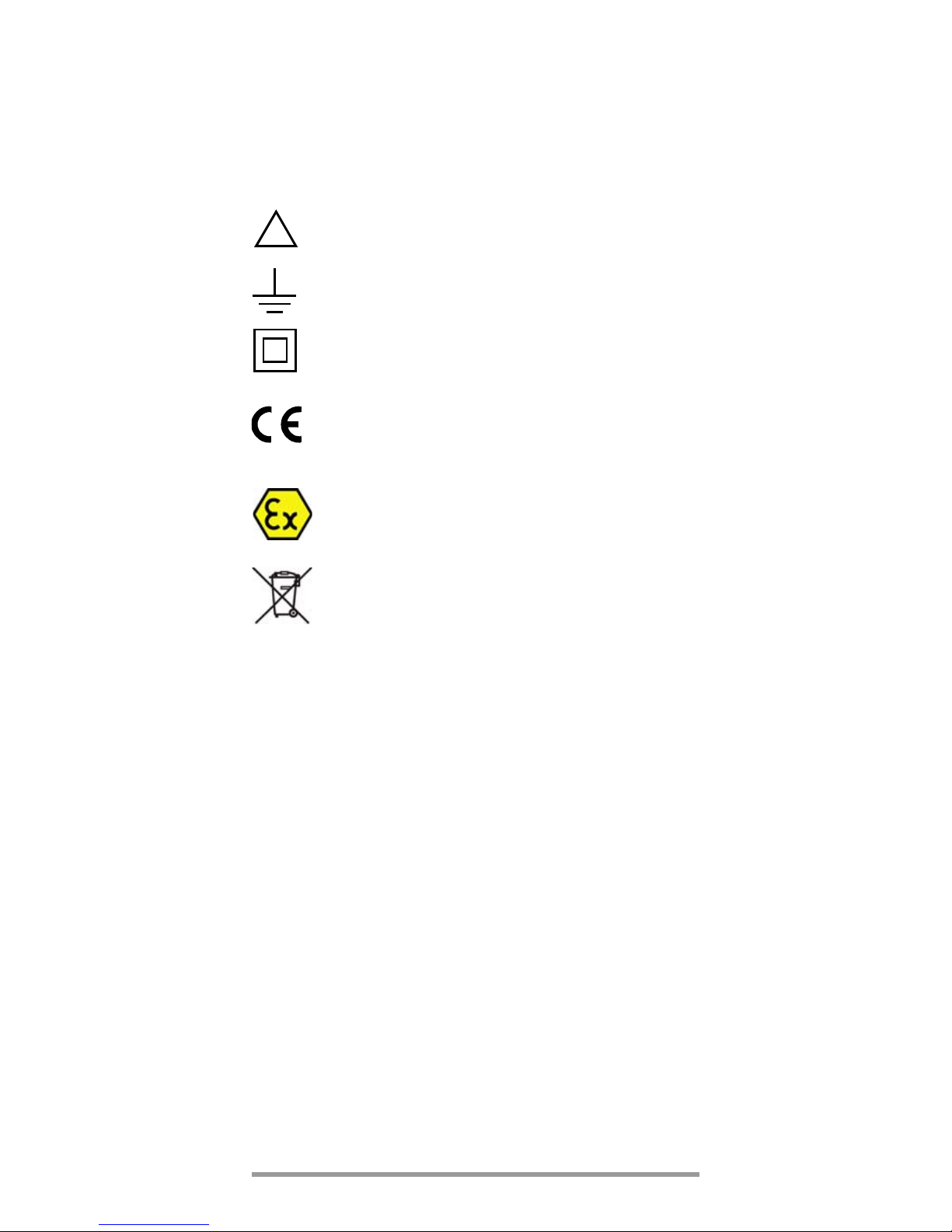
Meanings of symbols on the instrument:
Warning concerning a source of danger
(attention: observe documentation!)
Ground
Continuous, doubled or reinforced
insulation
Indicates EC conformity
Symbol for explosion protection:
Electrical equipment for intended use in
potentially explosive environments per
EN 60079-11
This device may not be disposed of with the
trash. Further information regarding the WEEE
mark can be accessed on the Internet at
www.gossenmetrawatt.com by entering the
search term ’WEEE’.
Repair, Parts Replacement and Balancing
When the instrument is opened, voltage conducting parts
may be exposed. The instrument must be disconnected
from the measuring circuit before the performance of
repairs, the replacement of parts, or balancing. If
balancing, maintenance or repair of a live open instrument
is required, this may only be carried out by trained
personnel who are familiar with the dangers involved.
Defects and Extraordinary Strains
If it may be assumed that the instrument can no longer be
operated safely, it must be removed from service and
secured against unintentional use. This applies particularly
for potentially explosive environments.
Safe operation can no longer be relied upon,
• If the instrument or the test probes are damaged
• If the instrument no longer functions
• If the limits of the overload capacity have been
exceeded, e.g. after the fuse has blown
• After long periods of storage under unfavorable condi-
tions (e.g. humidity, dust, or excessive temperature),
see „Ambient Conditions“ on page 29.
!
Page 8
8 GMC-I Messtechnik GmbH
3Initial Start-Up
Insert Batteries
Warning!
Remove the instrument from the potentially explosive environment before opening.
Only use the included type-tested batteries, as indicated in the Characteristic Values.
Refer to chapter 10.1 regarding correct battery installation.
Note!
As a result of internal voltage monitoring, the instrument may respond as follows if the battery voltage
level is low:
– Cannot be switched on
– Shuts back down immediately
– Shuts back down immediately when a load is
applied in the mΩ range.
If this is the case, replace the batteries.
Warning!
Never replace the batteries in potentially explosive
atmospheres.
Switching the Instrument On Manually
➭ Press the ON|OFF key.
As long as the key is held depressed, all of the segments at the LCD are illuminated. The LCD is shown
on page 2. Power-up is acknowledged with a brief
acoustic signal.
The instrument is ready for use as soon as
the key is released.
Switching the Instrument On with a PC
After transmission of a data frame from the PC, the milliohmmeter is switched on. See also chapter 8.6.
Switching the Instrument On Automatically
The milliohmmeter is switched on automatically in the
transmission and memory modes.
Note!
Electrical discharge and high frequency interference may cause
incorrect displays to appear, and may disable the measuring
sequence. In such cases, switch the instrument off and back on
again in order to reset. If the problem persists, briefly dislodge
the batteries from the connector contacts.
Setting Time and Date
See chapter 8 on page 17.
Switching the Instrument Off Manually
➭ Press the ON|OFF key until OFF is shown on the display.
Page 9

GMC-I Messtechnik GmbH 9
GB
Shutdown is acknowledged with two, brief acoustic signals.
Switching the Milliohmmeter Off Automatically – „SLEEP MODE“
The instrument is switched off automatically if none of the
keys are activated for approximately 10 minutes. Shutdown is acknowledged with a brief acoustic signal.
Transmission mode: In this case, checking is first performed
to determine whether or not the sampling rate has been set
to a value of greater than 10 s. The instrument is switched
off after 10 minutes, but the instrument is reactivated 10 s
before data is to be saved to memory. The instrument is
then switched back off again.
In the transmission mode, the instrument can be manually
activated with the ON|OFF key. After activation of this type,
the instrument returns to the “SLEEP MODE”.
If the instrument is to be fully shut down, it must first be
activated and then switched off with the ON|OFF key. This
ends both memory mode and transmission mode
operation.
We recommend setting the instrument to continuous
operation for transmission mode operation.
The continuous operation mode is not effected by automatic shutdown.
Disabling Automatic Shutdown
The instrument can be set to continuous operation.
➭ Press and hold the MENU/ESC key and then switch the
instrument on by pressing the ON|OFF key. Continuous
operation is indicated at the display with the symbol.
Switching LCD Illumination On and Off
➭ Briefly press the ON|OFF key after the instrument has al-
ready been switched on.
Illumination is switched off automatically after approximately 2 minutes.
Note: Electrical discharge and high frequency interference
may cause incorrect displays to appear, and may disable
the measuring sequence. In such cases, switch the instrument off and back on again in order to reset.
If the problem persists,
1 leave the potentially explosive environment,
2 disconnect the instrument from the measuring circuit before open-
ing and refer to chapter 10.1 „Batteries“,
3 Briefly dislodge the batteries from the connector contacts.
Page 10
10 GMC-I Messtechnik GmbH
4 Selecting Measuring Functions and Measuring
Ranges
4.1 Automatic Measuring Range Selection
The milliohmmeter is equipped with auto-ranging for all
measuring ranges. Auto-ranging is active as soon as the
instrument is switched on. The instrument automatically
selects the measuring range which allows for highest possible resolution for the applied quantity.
The instrument automatically switches to the next highest
or next lowest measuring range for the following measured
quantities:
4.2 Manual Measuring Range Selection
Auto-ranging can be deactivated and measuring ranges
can be selected manually in accordance with the following
table.
The manual mode is deactivated by pressing and holding
the MAN|AUTO key (approx. 1 s) or by switching the instrument off and then back on again.
Note!
If the red ERROR LED lights up and OL is shown
on the display during manual measuring range
selection, you should switch to the next higher
range.
4.3 Quick Measurements
If you wish to perform quicker measurements than those
possible with the automatic measuring range selection
function, make sure to establish the appropriate measuring
range and to perform the following two functions:
•by manual measuring range selection, i. e. by selecting
the measuring range with the best resolution, see
chapter 4.2.
or
Measuring Ranges
Resolution
Switching to next
highest range
at +(... d + 1 d)
Switching to next
lowest range
at +(... d –1 d)
300 mΩ, 3 Ω, 30 Ω 4 ¾ 31 000 2 800
30 mΩ 3 ¾ 3 100 280
MAN|
AUTO
Function
Acknow-
ledgement
Display
Acoust.
Signal
short
Manual mode active:
utilized measuring range is fixed
MAN 1 x
short
Range switching sequence for:
mΩ:30mΩ→ 300 mΩ→ 3 Ω→ 30 Ω→ 30 mΩ→ …
MAN 1 x
long Return to automatic range selection
—
2 x
Page 11
GMC-I Messtechnik GmbH 11
GB
•via DATA function, see chapter 6.1. After the first mea-
surement, the proper measuring range will be automatically determined so that measurements are performed more rapidly from the second measured value
onwards.
With both functions, the established measuring range is
maintained for the subsequent series mode measurments.
5 Triple Digital Display
The three digital displays (1 main display and 2 auxiliary
displays) show the measured value with decimal and plus
or minus sign. The selected unit of measure is displayed as
well.
“0L” (overload) appears if the measuring range upper limit is
exceeded for the following measured quantities (the red
ERROR LED lights up simultaneously and openl appears
on the auxiliary display):
300 mΩ, 3 Ω, 30 Ω: 30999
30 mΩ: 3099
The digital display is refreshed at different frequencies for
the various measured quantities.
The main display appears immediately after the milliohmmeter is switched on, but the auxiliary displays have to be
activated by pressing the DATA | CLEAR key.
In the following flowcharts, the initial displays are highlighted through the use of a bold border line.
023.00
022.00 data
mΩ
Auxiliary Display Auxiliary Display
MAN
Main Display
Page 12

12 GMC-I Messtechnik GmbH
6 Measured Value Storage
The METRA HIT⏐ 27EX provides two entirely different
options for storing data:
• Measured Value Memory – DATA Key Function:
Each time the DATA key is pressed and a measuring
point is contacted, a measured value is stored (see
chapter 6.1).
• Memory Mode Operation – STORE Menu Function:
After activating the STORE menu function, all measured values are saved in accordance with the
selected sampling rate. Memory mode operation is
ended manually using the same menu function, see
chapter 8.2.
In both cases, saved measured values can be read out
with the help of METRAwin
10 PC software (as of version
5.22). However, read-out is only possible if a IR adapter
(BD232 or USB-HIT) has been plugged into the METRA
HIT⏐27EX and connected to the PC with an interface cable
(see Data Interface page 29).
6.1 Measured Value Storage – Key Function “DATA”
Measured values can be automatically “frozen” with the
DATA hold function. This is useful when, for example, contacting the measuring points with the test probes requires
your full attention.
Preparation of Measurement
Memory should be cleared before starting a measurement
series with the DATA key function.
This assures, on the one hand, that adequate memory
capacity is available and, on the other hand, that only data
from the last measurement series are read out in a contiguous fashion. Check current memory occupancy to this
end: INFO MEMO/OCCUP
Clear memory if required: MEMO CLEAr.
Performing Measurements
➭ Press the DATA key.
The message data blinks and indicates readiness for
acquiring the first measured value.
➭ Contact the measuring point as described in chapter
7.3.
After applying the test probes to the measuring point:
– the green LED OK indicates: safe measurement connection.
– The initially acquired value is transferred to the main
display where it remains stored. This is acknowledged
by two successive acoustic signals.
„MAN“ (and, additionally, „ZERO“ in the MΩ measuring
ranges) is displayed simultaneously and indicates that
the measuring range is now fixed.
– the momentary measured values continue to be
shown in the auxiliary display on the left.
➭ Lift the test probes from the measuring point.
The message openl appears on the auxiliary display.
Page 13

GMC-I Messtechnik GmbH 13
GB
The red LED ERROR lights up as long as no contact has
been established between the test probes and the measuring point. The green LED OK continues to light up when
a valid measured value has already been stored.
Prior to contacting the next measuring point, the function
DATA must be activated once more by pressing the DATA
key. The message data blinks and indicates readiness for
acquiring the next measured value.
As long as the DATA function is active and all measurements are within the measuring range which has been
Acoustic signal 1x
0.L
openl
Ω
0.L
0.ldata
Ω
DATA
044.66
044.59 data
mΩ
MAN
Acoustic signal 2x
Meas. Contact
044.66
openl data
mΩ
MAN
Acoustic signal 2x
Disconnect contact
Acoustic signal 1x
DATA
044.66
openl data
mΩ
MAN
blinks
blinks
blinks
blinks
blinks
ERROR OK
OK
ERROR
OK
OK
ERROR
ERROR
ERROR
OK
ZERO
ZERO
ZERO
Page 14

14 GMC-I Messtechnik GmbH
automatically adjusted, the measuring ranges should not
be changed manually.
The DATA function is deactivated if the DATA|CLEAR key is
pressed and held (approx. 1 s) or by switching the instrument off and back on again.
7 Milliohm Measurement (4-Pole-Measurement)
7.1 Compensation of Cable Resistance
Electrical resistance is a dipole quantity which can
generally only be measured using two poles. This is
accomplished by directing a measuring current of
predetermined magnitude through the device under test,
and measuring the resultant voltage drop. The respective
resistance value is derived from the quotient of these two
values.
The two points between which voltage is measured are
decisive as regards the results of the measurement. All
resistances between these two points add to the
measured resistance value. These include contact
resistance, as well as cable resistance. If a very low
resistance value needs to be measured, for example
contact resistance at a contactor with a value of only a few
milliohms, the points between which voltage is measured
must be moved out of the measuring instrument and
positioned as closely as possible to the device under test.
For this reason, the measuring instrument is equipped with
separate jacks for current feed and voltage measurement.
This type of 4-pole connection is known as connection
according to Kelvin.
KC4 Kelvin clips and KC27 Kelvin probes (available as
accessories) allow for easy, correct connection.
7.1.1 Measurement with Kelvin Probe KC27
mΩ
U+U–
I+
red
black
black
Milliohm measurement on
conductor bars, welds,
coils, etc. with Kelvin probe
KC27 and Kelvin clip KC4
Direct the spring-loaded test
probe inward towards the DUT,
if possible, as it is connected
via the red plug with U
+
or U–
(Sense) .
I–
Page 15

GMC-I Messtechnik GmbH 15
GB
7.2 Thermovoltage Compensation
Thermovoltages which occur as a result of material and
temperature differences may distort measurement results.
For this reason, the instrument is equipped with automatic
thermovoltage compensation in the relevant measuring
ranges.
After switching on the milliohmmeter, „termoc“ is displayed,
indicating that an automatic thermovoltage compensation
for the 30 mΩ and 300 mΩ measuring ranges will be performed in the background for all future measurements.
ZERO signals that the value of the thermovoltage has
already been taken into account for the indicated measuring result.
After the first measurement – lift the test probe from the
measuring point – „termoc“ disappears to facilitate the reading of the measured values. The automatic thermovoltage
compansation remains activated.
000.10
termoC
m
mΩ
Ω
Measure
thermovoltage
Relevant measuring ranges:
30 mΩ und 300 mΩ
I < 100 mA
ZERO
Page 16

16 GMC-I Messtechnik GmbH
7.3 Milliohm Measurement with ≤ 100 mA DC [mΩ]
➭ Make sure that the device under test is voltage-free.
➭ Connect the device under test as shown.
KC4 Kelvin clips and KC27 Kelvin probes (available as
accessories) allow for easy, correct connection.
Resistance at the current jacks should amount to <1Ω.
➭ If applicable, select the desired measuring range using
the MAN|AUTO key: 30 mΩ, 300 mΩ, 3 Ω or 30 Ω.
➭ Contact the measuring point.
The green LED OK must light up.
Note!
If the measuring current is interrupted during
4-wire-mΩ-measurement or if the fuse F1 is defective, the message „open L“ flashes on the display
and the red LED ERROR lights up.
If fuse is defective, see chapter 10.2.
mΩ
U+U–
R
x
Voltage Drop Measuring Current
mΩ: 0.01 mΩ … 30 Ω
Overall Measuring Range:
+–
Measurement Cables,
KC27 or KC4
Note:
When using KC27 or
KC4 always set red
probe plug at U
+
or
U
–
, respectively.
I+
I–
Page 17

GMC-I Messtechnik GmbH 17
GB
8 Using the Menus – from the Initial InFO Menu to
Operating and Measuring Parameters
Menu-driven operation via the initial „1NF0 “ menu allows
the user to query online help, activate the memory and
query memory occupancy, activate the interface and
configure device parameters.
➭ The initial „1NF0 “ menu is accessed by simultaneously
pressing and holding the MENU/ESC and ON|OFF keys
with the instrument switched on, until „1NF0 “ appears
at the display.
➭ The display can be switched from the main „1NF0 “
menu to the other main menus including “store“,
“memo”, “ send” and “set”, and then back to the „1NF0 “
menu, by repeatedly pressing the keys.
➭ After accessing the desired main menu, the associated
submenus are opened by activating the key.
➭ The desired parameter or the desired function is se-
lected by repeatedly pressing the keys.
➭ Acknowledge with the key in order to change the
corresponding parameter or parameters.
➭ After the desired digit has been selected with the
keys and the value has been adjusted with the
keys, the next digit is accessed with the key, or the
display is returned to the start menu or switched to the
next submenu.
➭ The measuring mode is started by repeatedly pressing
the MENU/ESC key until the measuring display appears.
➭ The milliohmmeter is switched off by pressing and
holding the ON|OFF key until the display goes blank.
The following pages include an overview of the menu
structure.
8.1 Sampling rAtE
The sampling rate specifies the time interval after which the
respective measured value is transmitted to the interface or
to measured value memory. See page 24 for possible settings. The lower limit of the sampling rate which cannot be
fallen short of, is 0.5 s.
Page 18

18 GMC-I Messtechnik GmbH
8.2 Saving Measured Values
The METRA HIT⏐ 27EX provides two entirely different
options for storing data:
• Messwertspeicherung – Tastenfunktion DATA:
Measured Value Memory – DATA Key Function:
Each time a measuring point is contacted, a measured
value is stored in accordance with a defined condition
(see chapter 6.1 and chapter 8.2.1).
• Memory Mode Operation – STORE Menu Function:
After activating the STORE menu function, all measured values are saved in accordance with the
selected sampling rate. Memory mode operation is
ended manually using the same menu function.
In both cases, saved measured values can be read out
with the help of METRAwin
10 PC software (as of version
5.22). However, read-out is only possible if a BD232 IR
adapter has been plugged into the METRA HIT⏐ 27EX and
connected to the PC with an interface cable.
8.2.1 Memory Mode – DATA Key Function (see also chapter 6.1)
The instrument is equipped with a measured value
memory (32 kB) which is synchronized with a quartz
movement, and has an average capacity of 1000
measured values. Minimum capacity is 800 measured
values and maximum capacity is 1200 measured values.
Data are stored and can be transmitted directly to a PC
with the METRAwin
10 software. Date and time must be
reset if the batteries are depleted and/or replaced.
Measured values are stored in so-called blocks. Measured
values resulting from the same measuring function are
saved to the same block.
Only absolute values and absolute time stamps can be
saved, i.e. no relative or Δ values, and no relative time
stamps.
Memory content can only be read out with the help of a
PC, an IR adapter (BD232), and METRAwin
10 analysis
software.
Stored measurement data blocks are retained even if the
instrument is without voltage supply.
Vorbereitungen für den Speicherbetrieb
Preparing for Memory Mode Operation
➭ First set the sampling rate for memory mode operation,
and then start memory mode operation.
The sampling rate can also be changed during memory mode operation.
➭ First select the desired measuring function and an ap-
propriate measuring range.
➭ Check the battery voltage level before starting long-
term measurement recordings (see chapter 10.1 on
page 30).
Page 19

GMC-I Messtechnik GmbH 19
GB
8.2.2 Memory Mode Operation – STORE Menu Function
➭ First set the sampling rate for memory mode operation,
and then start memory mode operation.
The sampling rate can also be changed during memory mode operation.
➭ First select the desired measuring function and an ap-
propriate measuring range.
➭ Check the battery voltage level before starting long-
term measurement recordings, see chapter 10.1 on
page 30.
Starting Memory Mode Operation with Menu Functions
➭ Open the “Operating Mode” menu (refer to the menu
diagram) and select the StorE function.
➭ Now activate the key to open the start menu for
memory mode operation: StArt blinks.
Activate the key once again in order to start memory
mode operation: REM appears at the display.
➭ Press the key in order to switch to the measuring
function.
The “SLEEP MODE” is still active, i.e. the device is
switched on and off automatically at sampling rates of long
duration (see chapter 3).
When memory capacity has been exhausted, MEMO FULL
appears at the display, and an acoustic signal is generated
simultaneously. The signal can be deactivated by pressing
any key.
REM Display
The REM symbol indicates that memory mode operation
has been activated via menu function STORE.
Press the key if you wish to monitor the measured values also during the memory process.
The „STORE“ function cannot be started while the „DATA“
function is activated.
Exiting Memory Mode Operation with Menu Functions
➭ Select the StorE menu.
➭ Activate the key: StOP blinks.
➭ Activate the key once again: the auxiliary displays
are cleared. Memory mode operation has now been
deactivated.
➭ Press the key in order to return to the measuring
function.
➭ Memory mode operation can also be exited by switch-
ing the instrument off.
8.3 Querying Memory Occupancy – INFO MEMO/OCCUP
Memory occupancy can be queried from the „1NF0 “ menu.
The main display shows current occupancy as a percentage between 001 and 100%.
Page 20

20 GMC-I Messtechnik GmbH
8.4 Clearing the Memory – MEMO CLEAr
Attention!
!
This function deletes all measured values from
memory.
This function cannot be performed during memory mode;
bUSY
MEMO
is displayed instead of CLEAR.
8.5 Activating the Default Values
Previously entered changes can be undone, and the
default settings can be reactivated. This may be advisable
after the occurrence of software or hardware errors.
➭ Simultaneously press and hold the MENU/ESC, MAN| AUTO
and DATA | CLEAR keys, and switch the instrument on
with the ON| OFFkey.
Page 21

GMC-I Messtechnik GmbH 21
GB
8.6 Transmission Mode Operation with RS 232 or USB Interface
The METRA HIT⏐ 27EX is equipped with an bidirectional
infrared interface for the transmission of measurement data
to a PC. Data are transferred optically through the
instrument housing by means of infrared light to an
interface adapter (accessory BD232 or USB-HIT), which is
attached to the instrument. The adapter’s RS 232 or USB
interface allows for the establishment of a connection to
the PC via an interface cable. Beyond this, commands and
parameters can be transmitted from the PC to the
instrument as well. The following functions can be
executed:
• Configuration and read-out of measuring parameters
• Measuring function and measuring range selection
• Start measurements
• Read out measured values.
Activating the Interface
The interface is switched on manually as described below
for transmission mode operation. The instrument
continuously transmits measurement data to the PC via the
interface adapter in this operating mode. The interface is
activated automatically by the PC for receiving operation
(i.e. the instrument receives data from the PC).
Starting Transmission with Menu Functions
InFO SEnd StArt
The symbol blinks at the display in order to indicate
interface operation.
Automatic Activation and Deactivation of the Transmission Mode
If the sampling rate is 20 s or longer, the display is
switched off automatically between samples in order to
prolong battery service life.
Exception: continuous operation
As soon as an event occurs, the display is automatically
switched back on.
Configuring Interface Parameters
Addr – Address
If several milliohmmeters are connected to the PC via interface adapters, an unique address must be assigned to
each device. Address 1 should be used for the first device,
address 2 for the second etc. If only one milliohmmeter is
utilized, an address between 1 and 14 should be used.
Address 15 is not used for addressing, i.e. the device with
address 15 always responds, regardless of the actual
address.
Page 22

22 GMC-I Messtechnik GmbH
Main Menus and Submenus
1nf0
mem0
+
send
Set
MENU/ESC
ON
Clear
yes no
send
0ff/0n start/st0p
Current
Status
3.9
batt
V
8 01
mem0 oCCUp
set
rate
Battery
Voltage Level
↵
Memory Occupancy
(see chapter 8.3)
store store
0ff/0n start/st0p
2x
ESC
ESC
ESC
ESC
Page 23

GMC-I Messtechnik GmbH 23
GB
Selection must blink:
YES: delete memory
no: do not delete
Acknowledge
selection
StArt blinks
Activate:
Transmission mode
StOP blinks
Activate:
no Transmission mode
t im e
12:58 :08
d a t e
15 08 . 02
Current Time Current Date
Delete Memory Menu (see
chapter 8.4)
Transmission Mode (see chapter 8.6)
Configure Device Parameters (see chapter 8.1)
Query Information
!
t C a l
15 08 . 02
Calibration Date
t a d J
15 08 . 02
Balancing Date
blinks
does not blink
Display „EMPTY “: Memory is empty
Memory Mode Menu
StArt blinks
Activate:
Memory mode active
StOP blinks
Activate:
Memory mode inactive
REM is displayed REM disappears
During memory
mode the memory
cannot be deleted,
bUSY
MEMO
is displayed instead of
CLEAr.
active
See next page for
more submenus
Page 24

24 GMC-I Messtechnik GmbH
SEt Submenu for rAtE, Addr, dAtE and tIME Parameters
set
rate
set
addr
set
tIme
set
00:10:00 rate
set
15 addr
set
13:15:21 t Ime
set
13.08.02 date
Continued from previous page
set
date
ESC
ESC
ESC
ESC
Page 25

GMC-I Messtechnik GmbH 25
GB
Change
Value
Acknowledge
Sampling Rate
00:00:01, 00:00:02, 00:00:05, 00:00:10, 00:00:20, 00:01:00
00:02:00, 00:05:00, 00:10:00, 00:20:00, 01:00:00; 0.50 = 500 ms
Possible Settings
Change
Value
Set Device Address
Acknowledge
Address
Change
Value
Set Time
Acknowledge
Selection
Set Date
Select
Position
Change
Value
Acknowledge
Selection
Select
Position
Possible Settings
Possible Settings
Digits
blinks
Possible Settings (see also chapter 8.6): 0 … 15
Set Sampling Rate (see also chapter 8.1)
(hh:mm:ss, h = hours, m = minutes, s = seconds)
(hh:mm:ss, hh=hours, mm=minutes, ss=seconds)
(TT:MM:JJ, TT=day, MM=month, JJ=year)
Page 26

26 GMC-I Messtechnik GmbH
9 Characteristic Values
1)
Display:
4¾ places in the range of 300 mΩ, 3 Ω, 30 Ω,
3¾ places in the range of 30 mΩ,
A different sampling rate can be selected in the rAtE menu for saving and
transmitting measured values.
2)
at 0 °…+40°C
3)
In the event of an overload (connections I+, I–), the integrated 500 mA/600V
fuse is triggered.
4)
applies as from 10% of the measuring range
EX parameters: Vo = 6 V, Co = 559 μF, Io = 576 mA,
Lo = 300 μH, Po = 0,785 W
Key
rdg. = measured value, d = digit, 4 L = 4-wire measurement
Influencing Quantities and Influence Error
1)
With zero balancing
1)
With zero balancing
Real-Time Clock
Accuracy ±1min/month
Temperature Influence 50 ppm/K
Reference Conditions
Ambient temperature +23 °C ±2K
Relative humidity 40 ... 60%
Battery voltage 5.0 V ±0.1 V
Measuring
Function
Measuring
Range
Resolution at Upper
Range Limit
4¾ 30000 / 3¾ 3000
1)
Open-circuit
voltage approx.
Meas. cur-
rent approx.
mΩ
(4 L)
30 mΩ 0.01 mΩ
4 … 6 V
100 mA
300 mΩ 0.01 mΩ 100 mA
3 Ω 0.1 mΩ 10 mA
30 Ω 1mΩ 10 mA
Measuring
Function
Intrinsic Error at Max. Resolution
under Reference Conditions
Overload Capacity
2)
±(...% rdg. + ... d) Value Time
mΩ
(4 L)
30 mΩ 2 + 20
±0.6 V
3)
cont.
300 mΩ 1 + 20
4)
3 Ω 1 + 10
30 Ω 1 + 10
Influencing
Quantity
Sphere of
Influence
Measuring Range
1)
Influence Error
± (... % rdg. + d)/10 K
Temperature
0 … +21 °C
and
+25…+40 °C
mΩ, Ω 1 + 10
Influencing
Quantity
Sphere of
Influence
Measuring Range
1)
Influence Error
Relative
humidity
90 %
3 days
instrument off
All measured
quantities
1 x intrinsic error
Page 27

GMC-I Messtechnik GmbH 27
GB
Response Time
Response time (after manual range selection)
* without parallel capacity
Display Elements
LCD panel (65 mm x 30 mm) with triple 7 segment display
(measured values), units of measure and various special
functions.
Display / Char. Height 7-segment characters
Main display: 12 mm
Auxiliary displays: 7 mm
Number of places 4¾ places 30999 steps
Overflow display „0. L“ appears
LCD test All display segments available
during operation are briefly activated after the instrument is
switched on
Background illumination can be activated or deactivated
LED OK (green) lights up when contacting of
measuring point is OK
LED ERROR (red) lights up when measuring cur-
rent is interrupted (invalid measurement, poor contact, when „0. L“
is displayed)
Power Supply
Batteries 4 x 1,5 V PhilipsLonglife R6L4B
LR6 (AA-Size)
Service life
* 1 measuring cycle = 5 s
Additional consumption for:
Interface operation: 0.5 mA
LCD illumination: 40 mA at 6 V.
Battery test Range mΩ@100mA:
“ ” is displayed automatically if
battery voltage drops below
approx. 4.6 V.
The instrument is switched off if
battery voltage drops to below
approx. 4.3 V.
Fuses
Fusible link F1 for all
mΩ/Ω measuring ranges 500 mA/600 V AC;
breaking capacity 60 A at
600 V AC
For batteries F2 250 mA/125 V AC EX
Measuring Range
Response Time
for Digital Display
Measured Quantity
Step Function
mΩ, Ω 1.5 s
from ∞ to 50%
of upper range limit value
Measuring Function Number of Measurements *
mΩ@100mA > 500
Ω@10mA > 800
Page 28

28 GMC-I Messtechnik GmbH
Electrical Safety
Safety class II per IEC 61010-1:2010/
EN 61010-1:2011/
VDE 0411-1:2011
Measurement category 50 V CAT I
Contamination degree 2
EX marking CE 0080
II 2 G Ex ia IIA T4 Gb
Ex = prototype tested
II = Device group
2 = Device category
G = Atmosphere (gas)
Ex = conforms to European
Ex standards
ia = Type of protection
(intrinsic safety)
IIA = Explosion category
T4 = Temperature class
Gb = Equipment Protection
Level (EPL)
Tamb. = –10 °C ... +50 °C
(Tamb. = ambient temperature)
Prototype test certificate
INERIS 05ATEX0040
INERIS = Inspection and Certification Authority
05 = Year
ATEX = Guideline
(Atmospheres Explosives)
0040 = Test Report No.
Serial number (fabrication number)
X Y 123456 X = year of manufacture:
A → 2016, B → 2017 ...
Y = month of manufacture
January A
February B
March C
April D
May E
June F
July G
August H
September I
October J
November K
December L
123456 = serial number
AG123456 means for example = device was built in July 2016
Page 29

GMC-I Messtechnik GmbH 29
GB
Serial plate
GOSSEN METRAWATT manufacturer
Thomas-Mann-Str. 16-20
street
D-90471 Nürnberg post code / place
METRA HIT 27EX designation of device
INERIS 05ATEX0040
prototype test certificate see above
X Y 123456 serial number see above
II 2 G EX marking see above
EX ia IIA T4 Gb EX marking see above
Tamb.= –10°C ... +50°C
ambient temperature
Electromagnetic Compatibility (EMC)
Interference emission
Interference immunity EN 61 326-1:2006 Tab A1
Data Interface
Data transmission bidirectional, optical via infrared
light through the housing (read
data and configure parameters)
With interface adapter as accessory
USB-HIT IR to USB 1.1/USB 2.0,
single-channel operation
baud rate (MM ↔ PC) 9600 baud
Ambient Conditions
Accuracy range 0 °C ... +40 °C
Operating temperatures −10 °C ... + 50 °C
Storage temperatures −25 °C ... + 70 °C (w/o batteries)
Relative humidity 45% ... 90%,
no condensation allowed
Elevation up to 2000 m
Mechanical Design
Protection IP 54
Extract from table on the meaning of IP codes
Dimensions 84 mm x 195 mm x 35 mm
Weight approx. 380 g with batteries
(without GH18 protective rubber
cover)
IP XY
(
st
digit X)
Protection against
foreign object entry
IP XY
(2nd digit Y)
Protection against the
penetration of water
5 dust protected 4 splashing water
Page 30

30 GMC-I Messtechnik GmbH
10 Maintenance
10.1 Batteries
Warning!
Ex Environment: Remove the instrument from the
potentially explosive environment before opening.
Attention!
!
Non-Ex Environment: Disconnect the instrument
from the measuring circuit before opening to replace batteries!
Removing the Batteries During Periods of Non-Use
The integrated quartz clock draws power from the batteries, even when the instrument is switched off. It is advisable to remove the batteries during long periods of nonuse for this reason (e.g. vacation). This prevents excessive
depletion of the batteries, which may result in damage
under unfavorable conditions.
Checking Battery Voltage-Level and Condition
The current battery voltage level can be queried in the
“Info” menu (see chapter 8 on page 17):
MENU/ESC + ON|OFF InF0 X.X V (bAtt).
Make sure that no battery leakage has occurred before initial start-up, and after long periods of storage. Continue to
inspect the batteries for leakage at short, regular intervals.
– If battery leakage has occurred, carefully and completely
clean electrolyte from the instrument with a damp
cloth, and replace the batteries before using the instrument.
– If the “ ” symbol appears at the display, the batteries
should be replaced as soon as possible. You can continue working with the instrument, but reduced measuring accuracy may result.
Page 31

GMC-I Messtechnik GmbH 31
GB
Replacing the Batteries
Warning!
Use the included type-tested batteries only, as described in the Characteristic Values.
➭ Set the instrument face down onto a flat working sur-
face, loosen the two screws at the back and lift off the
housing base, starting at the bottom. The housing top
and housing base are held together with the help of
snap hooks at the top front.
➭ Remove the batteries from the battery compartment.
➭ Insert four 1.5 V batteries into the battery compart-
ment, making sure that the plus and minus poles
match up with the provided polarity symbols.
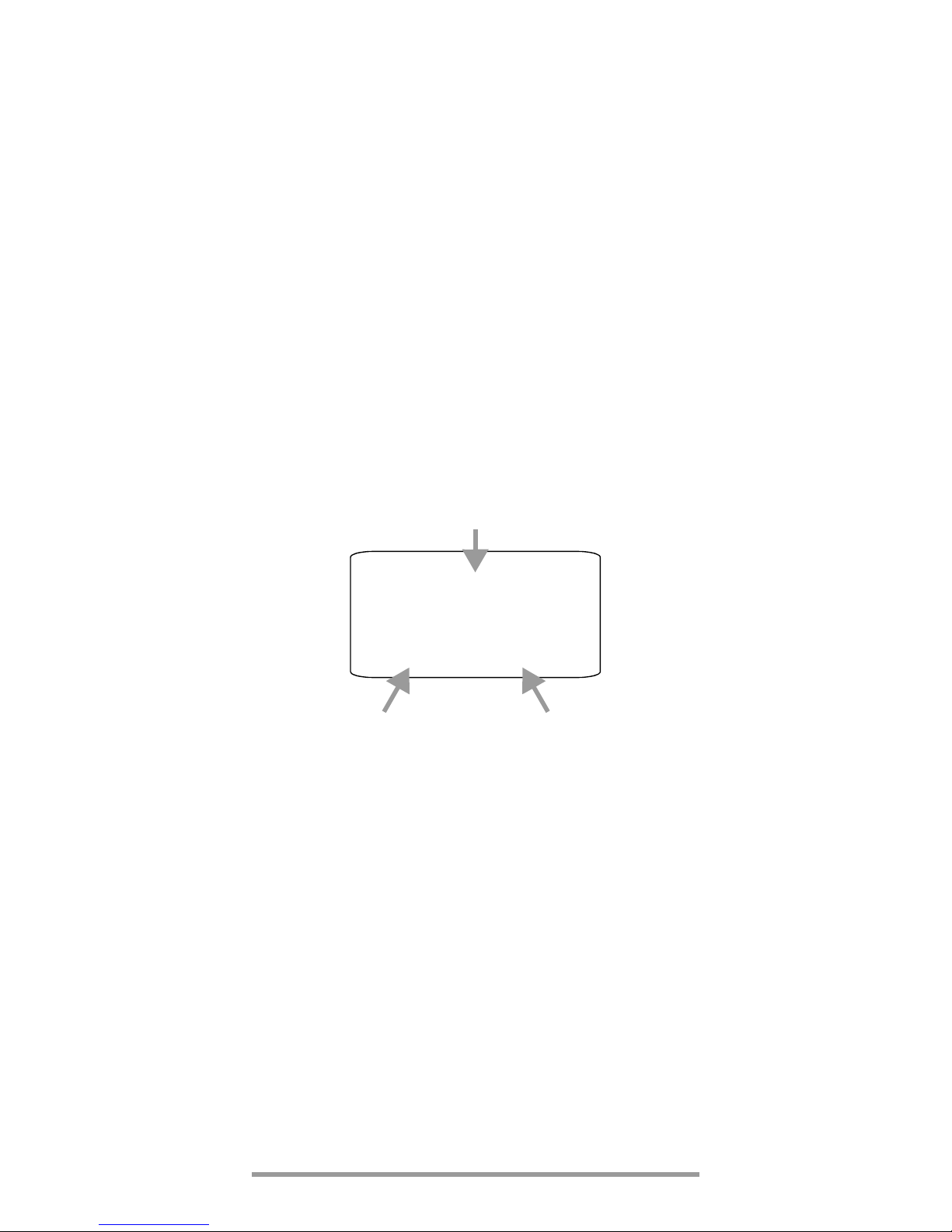
➭
Important for reassembly: First set the housing base
onto the housing top and align accurately (see photo
below). Then press the two housing halves together,
first at the bottom front (a), and then at the top front (b).
➭ Secure the housing base with the two screws.
Warning!
The instrument may not be operated if the housing
base has not been properly installed and secured!
Disposing of Batteries
Dispose of old batteries properly, i.e. at a designated collection point.
10.2 Fuses
Inspecting the Integrated Fuse F1
The fuse F1 is located at the measuring input. When the
fuse is defective, the measurements in the mΩ/Ω ranges
are faulty.
➭ Short circuit the „I+“ and „I–“ as well as the „U+“ and
„U–“ jacks.
Display < 0.4 Ω: fuse OK.
Display „0L“ and „openL“: fuse blown.
Attention!
!
If a fuse should blow, eliminate the cause of overload
before placing the instrument back into service!
(b) (a)
Page 32

32 GMC-I Messtechnik GmbH
Inspecting the Integrated Fuse F2
The fuse F2 is located in the battery supply path. If the LC
display is not active upon switching the instrument on:
➭ check whether the batteries have been inserted with
the polarity symbols at the correct end.
If the LCD remains inactive it might be defective.
Replacing the Fuses
Fuse F1 for the mΩ/Ω measuring ranges and fuse F2 for
the battery power supply are both firmly soldered in. They
are not intended to be replaced by the user.
If one of the fuses is defective, you are requested to send
the instrument to our repair service or to the respective
subsidiary abroad (the address is given in chapter 12).
This provides you with the guarantee that type-tested and/or
Ex-approved fuses with the correct triggering characteristics,
nominal current and breaking capacity are inserted. Additionally, the instrument will be subjected to a safety test.
Instructions for the service
Warning!
Ex Environment: Remove the instrument from the
potentially explosive environment before opening.
Attention!
!
Non-Ex Environment: Disconnect the instrument
from the measuring circuit before opening to replace batteries!
➭ Open the instrument in the same manner as for replac-
ing the batteries.
Warning!
Use the specified type-tested fuses only!
If fuses with other blowing characteristics, other
current ratings or other breaking capacities are
used, the operator is placed in danger, and protective diodes, resistors and other components
may be damaged.
The use of repaired fuses and short-circuiting the
fuse holder are prohibited.
10.3 Housing and Display
No special maintenance is required for the housing. Keep outside surfaces clean. Use a cloth slightly dampened with water
for cleaning.
Attention ! Do not under any circumstances use cleansers, abrasives and solvents !
This particularly applies to the display surface to avoid
damaging the high-quality explosion protection coating,
thus reducing its efficiency.
Page 33

GMC-I Messtechnik GmbH 33
GB
10.4 Collection of Used Instruments and Environmentally
Compatible Disposal
The milliohmmeter is a category 9 product (monitoring and
control instrument) in accordance with ElektroG (German
Electrical and Electronic Device Law). This device is subject to the RoHS Directive. Further-more, we make reference to the fact that the current status in this regard can
be accessed on the Internet at www.gossenmetrawatt.com by entering the search term WEEE.
We identify our electrical and electronic devices in
accordance with WEEE 2012/19/EU and ElektroG
with the symbol shown to the right per DIN EN
50419. These devices may not be disposed with
the trash. Please contact our service department regarding
the return of old devices. (see chapter 12).
If you use type-tested batteries in your instrument or accessories which no longer function properly, they must be duly
disposed of in compliance with the applicable national regulations.
Batteries or rechargeable batteries may contain harmful
substances or heavy metal such as lead (PB), cadmium
(CD) or mercury (Hg).
They symbol shown to the right indicates that
batteries or rechargeable batteries may not be
disposed of with the trash, but must be delivered
to collection points specially provided for this
purpose.
11 System Messages
The following messages appear at the main display, or the
auxiliary displays as required. See “Symbols used in the
Digital Display” on page 3 for messages displayed at visible
segments.
Blinking Unit of Measure
All measuring functions are balanced for each METRA
HIT⏐ 27EX at the factory in accordance with the respective
technical specification. If a unit of measure blinks, this indicates that balancing constants which have been established and saved to the milliohmmeter are no longer available for the respective function. If this is the case, measurement results may deviate from the specification. We
recommend sending the instrument to our Repair and
Replacement Parts department for rebalancing (see chapter 12).
Message Function Meaning
0. L Measuring Indicates overflow
open L
4-wire-mΩ
Measuring current interrupted or fuse defective.
Pb Cd Hg
Page 34

34 GMC-I Messtechnik GmbH
12 Repair and Replacement Parts Service,
Calibration Center* and Rental Instrument Service
If required please contact:
GMC-I Service GmbH
Service Center
Thomas-Mann-Straße 20
90471 Nürnberg • Germany
Phone +49 911 817718-0
Fax +49 911 817718-253
E-Mail service@gossenmetrawatt.com
www.gmci-service.com
This address is only valid in Germany.
Please contact our representatives or subsidiaries for service in other countries.
French subsidiary:
GMC Instruments France SAS
3, rue René Cassin
F-91349 Massy Cedex
Phone +33 1 69 20 89 49
Fax +33 1 69 20 54 92
E-mail info@gmc-instruments.fr
* DAkkS Calibration Laboratory for Electrical Quantities
D-K-15080-01-01 accredited as per DIN EN ISO/IEC
17025
Accredited quantities: direct voltage, DC value, DC resistance,
alternating voltage, AC value, AC active power, AC apparent
power, DC power, capacitance, frequency and temperature
Competent Partner
GMC-I Messtechnik GmbH is certified per
DIN EN ISO 9001.
Our DAkkS Calibration Laboratory has been accredited in
accordance with DIN EN ISO/IEC 17025 by the Deutsche
Kalibrierdienst (German Calibration Service) under registration number D-K-15080-01-01.
Our competence in the field of metrology covers test
reports, Proprietary Calibration Certificates as well as DAkkS
Calibration Certificates.
Our range of services is complemented by our Test Equipment Management service which is provided free of charge.
An on-site DAkkS calibration station is an integral part of our
service department. If any faults are detected during calibration, our specialists are able to carry out the necessary
repairs with original replacement parts.
Needless to say, in our function as calibration laboratory,
we calibrate all instruments, irrespective of the manufacturer.
Page 35

GMC-I Messtechnik GmbH 35
GB
13 Manufacturer’s Guarantee
The guarantee period for all METRA HIT digital multimeters
and calibration instruments is 3 years after date of shipment.
The guarantee covers materials and workmanship. Damage resulting from use for any other than the intended purpose or operating errors, as well as any and all consequential damage, is excluded.
The calibration certificate confirms that the product conformed to the specified technical data at the time of calibration. We guarantee the observance of the specified
technical data within the admissible tolerance limits for a
period of 12 months from delivery.
14 Product Support
If required please contact:
GMC-I Messtechnik GmbH
Product Support Hotline
Phone +49 911 8602-0
Fax +49 911 8602-709
E-Mail support@gossenmetrawatt.com
French subsidiary:
GMC Instruments France SAS
3, rue René Cassin
F-91349 Massy Cedex
Phone +33 1 69 20 89 49
Fax +33 1 69 20 54 92
E-mail info@gmc-instruments.fr
Attention!
!
Please refer to our website
www.gossenmetrawatt.com for up-to-date
information on the test instrument.
Page 36

GMC-I Messtechnik GmbH
Südwestpark 15
90449 Nürnberg • Germany
Phone+49 911 8602-111
Fax +49 911 8602-777
E-Mail info@gossenmetrawatt.com
www.gossenmetrawatt.com
Edited in Germany • Subject to change without notice
15 Recalibration
The respective measuring task and the stress to which
your measuring instrument is subjected affect the ageing of
the components and may result in deviations from the
guaranteed accuracy.
If high measuring accuracy is required and the instrument
is frequently used in field applications, combined with
transport stress and great temperature fluctuations, we
recommend a relatively short calibration interval of 1 year. If
your measuring instrument is mainly used in the laboratory
and indoors without being exposed to any major climatic
or mechanical stress, a calibration interval of 2-3 years is
usually sufficient.
During recalibration* in an accredited calibration laboratory
(DIN EN ISO/IEC 17025) the deviations of your instrument
in relation to traceable standards are measured and documented. The deviations determined in the process are
used for correction of the readings during subsequent
application.
We are pleased to perform DAkkS or factory calibrations
for you in our calibration laboratory. Please visit our website
at
www.gossenmetrawatt.com (→ Company → DAkkS Calibration Center or → FAQs → Calibration questions and
answers).
By having your measuring instrument calibrated regularly,
you fulfill the requirements of a quality management system
per DIN EN ISO 9001.
* Verification of specifications or adjustment services are not part of the cali-
bration. For products from our factory, however, any necessary adjustment
is frequently performed and the observance of the relevant specification is
confirmed.
 Loading...