

Page 1
Operating Instructions
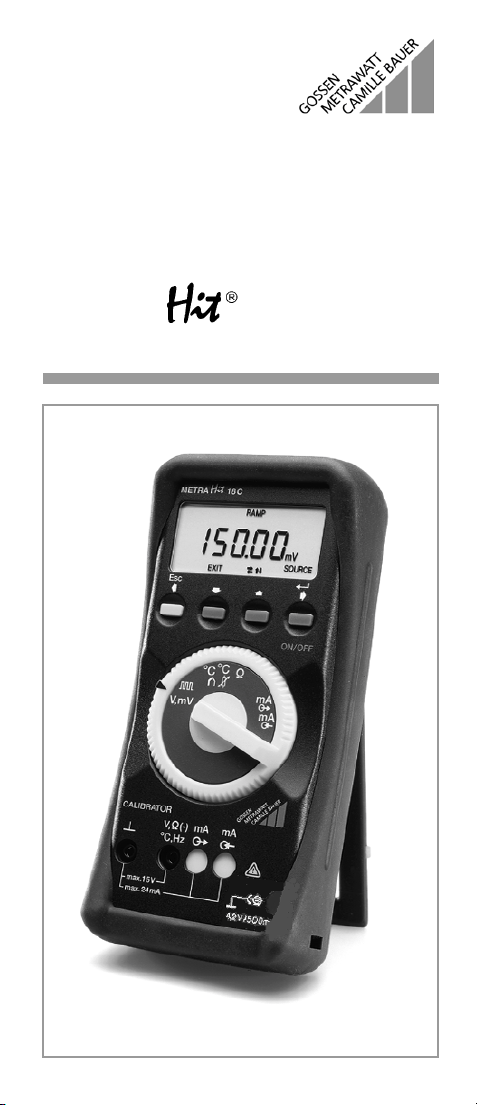
METRA 18C
Calibrator
3-348-715-15
5/1.02
Page 2
(1)
(2)
(3)
(4)
(5)
(6)
(7)
(8)
9)
10)
7)
8)
1)
6)
5)
2)
4)
3)
11)
16)
17)
12)
13)
18)
19)
14)
15)
2 GOSSEN-METRAWATT
Page 3
Operating Instructions
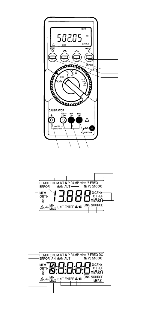
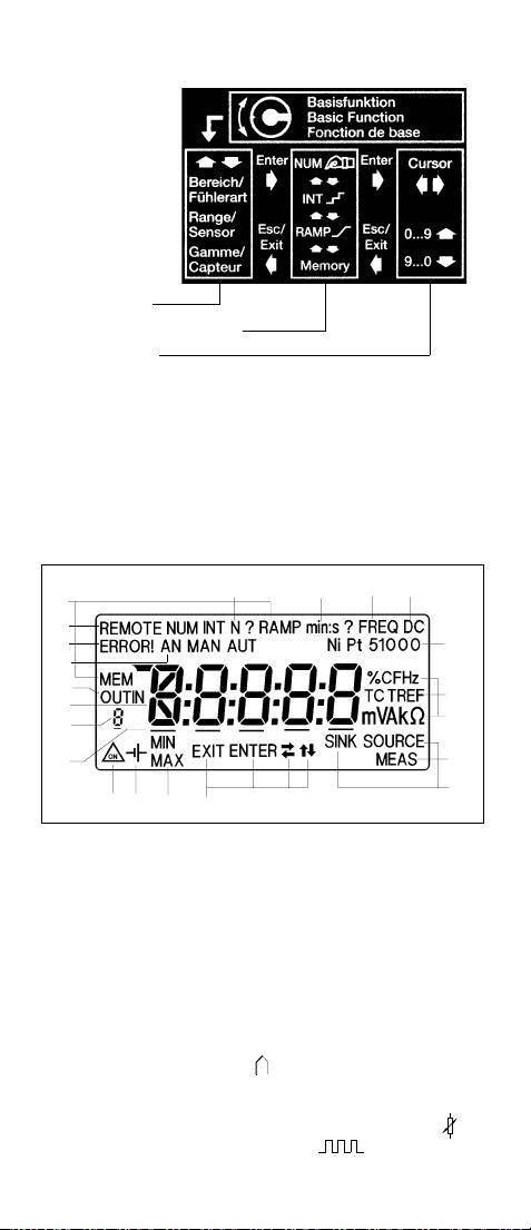
(1) LC display
(2) ON/OFF key, cursor right ENTER
(3) Key for digit increment, increasing step
(4) Key for digit decrement, decreasing step
(5) Key for cursor left, EXIT
(6) Functions selector for basic functions
V, mV = V, mV-source
= frequency, pulse
°C = thermocouple (TC) simulation
°C = RTD sensor simulation
W = resistance simulation
mA = mA-SOURCE
mA = mA MEAS, mA SINK
(7) Jack for plug type mains unit
(8) Jacks with automatic interlocking
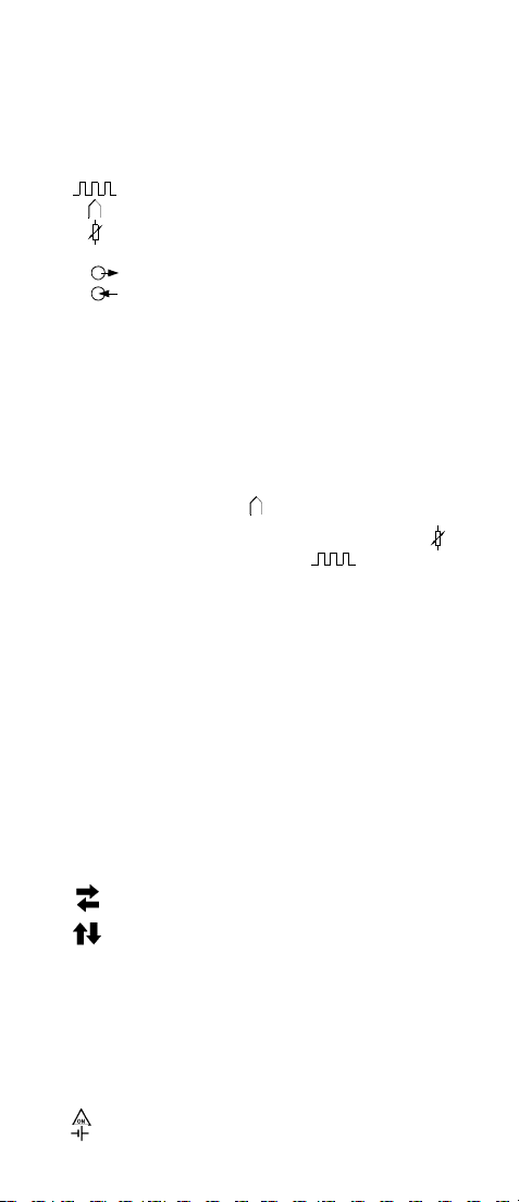
LC Display
1) 5-digit numeric display, 1st digit indicates type of thermocouple
2) Cursor field
3) Menu guidance symbols for basic functions
SOURCE = source, i.e. simulation of signals
SINK = sink, i.e. for simulating a 2-terminal transmitter
4) Measurement units for measured values
5) Menu guidance symbols
TC = basic function ”°C “, for thermocouple simulation
TREF = setting the reference temperature
6) Type of simulated RTD sensor, e.g. Pt100 in the basic function ”°C “
7) FREQ = pointing to the basic function ” “ = frequency or
8) Menu guidance symbols for types of signal output
NUM = numerical entry for the output signal
INT = intervals, output in N steps
RAMP = ramp output
MEM = memory, output from the non-volatile memory
9) N? = request for entry of the number of steps in output type INT
10) Menu guidance symbols for output method MEM using
MAN = number of steps by manual key action
AUT = number of automatic steps with selectable time per step
11) min:s = flashing menu guidance symbol for time entries
12) Menu guidance symbols for output method MEM using
OUT = output from memory
IN = input to memory
13) Number of the memory value or number of the procedure
14) Menu guidance symbols for permissible key operations
EXIT = key (5) for EXIT function (Esc)
ENTER = key (2) for ENTER function
15) MIN and MAX simultaneously
pointing out the ranges with selectable lower and upper range limits
MIN or MAX flashing
Menu guidance symbol when entering the lower range limit (MIN) or
the upper range limit (MAX) for output types INT and RAMP
MAX flashing
Upon entering the upper range limit during current measurement
16) Menu guidance symbol for REMOTE operation via the serial interface
17) ERROR ! = warning symbol for error states
18) = pointing out the inhibited automatic cut-out
19) = indication of "battery low" or for battery voltage indication
GOSSEN-METRAWATT 3
pulse output
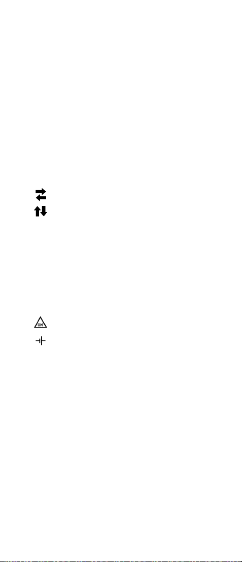
= keys (2) and (5) moving the cursor to the right (2)
or to the left (5)
= keys (3) and (4) for menu selection on the same level
modifying digits or step function
Page 4

Contents
Page
1 Safety Features and Precautions ....................................... 5
2 Putting into Operation ........................................................ 7
3 General Advice for Operation ............................................. 9
3.1 Key Panel ............................................................................. 9
3.2 Menu Structure and Key Operations ..................................... 10
3.3 LC display .......................................................................... 11
3.4 Operating Assistance by the LC Display ............................... 13
3.5 Entering Digits .................................................................... 13
3.6 Non-Volatile Saving of Menu Positions and Configurations .... 14
4 Types of Output Signals ................................................... 15
4.1 Menu Structure .................................................................. 15
4.2 Numerical or Manual Entries for the Output Signal (NUM) ...... 15
4.3 Intervals, Output in N Steps (INT) ......................................... 15
4.4 Output as Periodic Ramp (RAMP) ......................................... 18
4.5 Output from the Non-Volatile Memory (MEM) ........................ 20
4.6 Output by Prozedures Saved in the Non-Volatile Memory ...... 22
4.7 Output via the Serial Interface (REMOTE) .............................. 23
5 Basic Functions ................................................................ 25
5.1 General Notes .................................................................... 25
5.2 Supervisory Circuits ............................................................ 25
5.3 [V, mV], Voltage Source ...................................................... 28
5.4 , Pulse Generator ................................................... 28
5.5 [°C], Thermocouple Simulation ............................................ 31
5.6 [
°C], RTD Sensor Simulation ............................................... 33
5.7 [
W], Resistance Simulation ................................................. 34
5.8 , Current Source ......................................................... 34
5.9 Current Measurement [mA] ................................................. 35
5.10 , Current Drain, Simulation of a Transmitter
with two Leads ................................................................... 36
6 Technical Data ................................................................. 38
7 Maintenance .................................................................... 41
7.1 Batteries ............................................................................ 41
7.2 Housing ............................................................................. 42
8 Appendix .......................................................................... 43
8.1 Errors in [°C] in Thermocouple Simulation ............................ 43
9 Repair and replacement parts service ............................. 44
10 Product Support .................................................................44
4 GOSSEN-METRAWATT
Page 5

1 Safety Features and Precautions
This chosen instrument will provide a high degree of safety.
The calibrator is designed and tested in accordance with the safety regulations
IEC 61010-1 / DIN VDE 0411.
When used in accordance with the regulations, it will ensure the safety of the
operating personnel and protection of the instrument. However, safety is not
ensured when the instrument is operated improperly or treated carelessly.
To maintain a proper state of safety, and to ensure a hazard-free
use, the operating instructions must be read carefully and completely prior to the use of the instrument, and all points in the operating instructions must be complied with.
For the purpose of personal safety, and for the protection of the instrument, the
calibrator is provided with automatic jack interlocking.
This is coupled with the functions selector, and makes only those jacks accessible
that are required for the selected function. Furthermore, it inhibits switching into
wrong basic functions when the measurement leads are plugged in. Hence, only
the correct polarity of the connection as marked at the jacks need be verified.
Please observe the following safety precautions:
Attention!
The meter has been designed for safe use when not connected to
circuits which conduct hazardous contact voltages of greater than
42 V to earth.
• Never mistake the calibrator for the similarly housed multimeters.
The calibrator is distinguished from the multimeter by its YELLOW jack
sleeves and leads; the multimeter has red jack sleeves and red and black
leads.
• When intending to connect the instrument with a circuit, the absence of haz-
ardous touch voltages must be verified first, if necessary with a multi-meter.
• Please observe the maximum permissible voltages for the protection of the
instrument stated at the jacks.
Except during operation for resistance simulation and mA-SINK, the connected
signal circuits should not feed currents or voltages back into the calibrator.
In order to prevent major damages to the instrument when extraneous voltages
(within the permissible limits) are applied, the measuring circuit for mA-SINK
and mA-SOURCE is provided with a PTC resistor overload protection that turns
these measuring circuits into high resistance ones during the overload period
when higher currents occur during a fault.
Warning!
The instrument shall not be used in explosion endangered zones or
inserted in self-protected circuits.
GOSSEN-METRAWATT 5
Page 6

Repairs, Exchange of Parts, and Calibration
Voltage-carrying parts can be found exposed when the instrument is opened. The
instrument must be disconnected from measuring circuits before any repair,
exchange of parts or calibration. When repair or calibration work under voltage
and with an opened instrument is unavoidable, then this shall only be carried out
by a skilled person aware of the dangers that may arise.
Faults and Extraordinary Loading
When a continued hazard-free use of the instrument is doubtful, it must be made
inoperable and protected against inadvertent use.
A hazard-free use is no longer ensured when
• the instrument shows visible damage,
• the instrument no longer operates,
• the instrument has been kept in storage under adverse conditions,
• the instrument has been subjected to severe transport conditions,
• measurement leads or probe tips ar e damaged.
6 GOSSEN-METRAWATT
Page 7

2 Putting into Operation
Inserting Batteries
3 alkaline cells size IEC LR6, 1.5 V / 2.2 Ah are supplied inserted in the instrument. It is ready for operation.
Please note Section 7.1 Maintenance – Battery" prior to operating
the instrument.
In there, the additional statement is made that externally rechargeable batteries
may be used.
One of the accessories is a plug type mains power supply that permits driving the
instrument with power from the mains.
The internal batteries will be disconnected from the circuit when the plug is
inserted into the instrument. Thus, they cannot draw power from the mains power
supply.
Only this plug type power supply that is matched to the instrument
in respect of voltage and power, may be used.
Switching the Instrument On
➭ Press the "ON/OFF" key (2).
The switched-on state is acknowledged by a signalling tone.
Pressing the "ON/OFF" key (2) for a short period will cause the firmware ver-
sion stored in the EPROM and, subsequently, the battery or power supply voltage to be briefly displayed during switching on process, before the instrument
becomes operational in the operational mode selected with the functions
selector (6).
Pressing the "ON/OFF" key (2) for a longer period will cause all segments of
the LC display (1) shown in Section 3.3 to be displayed.
The instrument becomes operational when the key is released.
Attention!
The following can occur when the charge state of the batteries is
low: the internal battery voltage supervision causes the instrument
– not to switch on
– to switch off immediately afterwards
– to switch off when the output is loaded or
the internal change-over selects a higher auxiliary voltage
(e.g. 10/15 V range, 20 mA / 750
See also Section 5.2 and Section 7.1.
In this case, the batteries should be replaced
in accordance with Section 7.1 or
the plug type mains unit may be used, if possible.
When the instrument is operational, the last menu position will be saved in the
non-volatile memory (NVRAM) before the instrument is switched off.
Provided the position of the functions selector has not been changed during the
switched-off period, the instrument will, immediately after switching on, revert to
the menu position used prior to switching off.
Jumping to the highest menu level is achieved in the simplest way by turning the
functions selector into an adjacent position and back.
This switching process is also recommended after wrong menu operations or
uncertainties in respect of the actual menu setting.
W).
GOSSEN-METRAWATT 7
Page 8

+
Automatic Switching Off
The instrument is switched off automatically, if none of the keys or the function
selector have been activated for a period of approx. 10 min.
Inhibiting the Automatic Switching Off
The instrument can be set to "PERMANENTLY ON".
➭ When switching ON, the "ON/OFF" key (2) and the yellow "ESC" key (5) must
Note:
The function "PERMANENTLY ON" is indicated by the symbol on the LC display (1).
Automatic switching off is inhibited also when the instrument is set to REMOTE
operation via the serial interface in accordance with Section 6.
Switching the Instrument Off
Press the ON/OFF key (2) for at least 1 second.
Note!
Electrical discharge and RF interference may cause incorrect readings and disrupt the measuring sequence.
Then the instrument should be switched off and switched on in a
different position of the functions selector; this will reset the operation of the instrument.
Should this attempt fail, then the batteries should be disconnected
from the circuit for a short period. This can be done by plugging in
the power supply without opening the instrument.
Prior to opening the instrument, the latter must be disconnected
from the circuit to be measured, and Section 7 "Maintenance" must
be observed!
be pressed simultaneously.
8 GOSSEN-METRAWATT
Page 9
3 General Advice for Operation
3.1 Key Panel
The control operations required for the comprehensive facilities for signal outputs
are executed by using only the four keys (2) to (5) after the basic function has
been selected by means of the functions selector. Their effect depends on the
actual setting of the menu position, but follows a general control principle
described in Section 3.2.
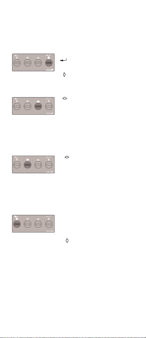
• Switching ON/OFF
ON/OFF
ENTER-function,e.g.
• Entering a sub-menu
(1)
• Loadng an entered number digit
• Moving the cursor to the right
when entering digits
• Incrementing a digit
• Stepping to an adjacent menu
(2)
(3)
on the same menu level
• Starting ramps and interval steps
upwards and stopping them
• Jumping back to the preceding program step (RECORD) under the basic
function PROCEDURES in accordance with Section 4.6
• Decrementing a digit
• Stepping to an adjacent menu
on the same menu level
• Starting ramps and interval steps
downwards and stopping them
• Jumping forward to the next program
step (RECORD) under the basic function PROCEDURES in accordance
with Section 4.6
Esc
EXIT-function, i.e.
• Back to the higher menu level
• Terminating ramps, automatic interval
(4)
GOSSEN-METRAWATT 9
stepping, frequency and back to the
higher menu level
• Moving the cursor left when entering
digits
Page 10

3.2 Menu Structure and Key Operations
The menu structure is designed on a uniform concept for nearly all basic functions.
The highest menu level comprises the basic functions that can be selected with
the functions selector (6). All other operations are executed by using the 4 keys in
accordance with a structure shown in Figure 1.
Menü 1
Menu 1 Menu 2 Menu A
Esc
Menu 1.1
Menü 1.1
Esc
Other sub-menus depending on the type of operation and output
Weitere Untermenüs je nach Betriebs- und Ausgabeart
1)
1. Key panel menu level of the selected type of operation (ranges or type of sensor)
1)
1. Tastatur-Menüebene der eingestellten Betriebsart (Bereiche oder Sensortypen)
2)
2. Key panel menu level, method of output for the selected range or type of sensor
2)
Figure 1 Concept of the Menu Structure
-
Menü 2
Esc Esc
Menu 1.1 Menu 1.1
Esc
Menü A
Menü 1.BMenü 1.2
Esc
1)
Menus X.Y
Menüs X.Y
X=2-A, Y=1-B
X=2-A, Y=1-B
Esc
The basic function “ “ and the “mA MEAS” function are excepted from
this menu structure.
Furthermore, the following is carried out between the 1st and 2nd menu levels in
the basic functions:
”°C “ selection of the internal and external reference temperature and
its entry, as well as
”°C “ entering the lead resistance
The following functions are associated with the various menu levels:
1st Menu Level 2nd Menu Level Other Menu Levels
Selection of the signal
ranges or of the types of
sensor depending on the
basic function selected
with the functions selector
Selection of the method
of signal output:
NUM = numerical Manual numerical input
INT- = subdivision of a
specified range into a number
of similar steps. The sequence
can be manual (MAN) or automatic (AUTO) with an adjustable
time per step
RAMP = output as an
ascending or descending ramp
with a dwell time at the upper
and lower range limits
MEM = output of 10 signal
values per range or type of
sensor that have been saved
earlier in the non-volatile
memory (NVRAM)
of the output value
Input of the lower and upper
range limits (these are already
defined for the standard r anges
0 ... 10 V, 0/4 ... 20 mA)
as well as entering the number
of steps. Under AUTO:
entering the time per step,
starting and stopping steps
Entering the lower and upper
range limits as well as ramp
duration ( ) and dwell
time ( ) Starting and
stopping the ramps
Entering
signal values into the
non-volatile memory (NVRAM)
and output from the NVRAM
2)
10 GOSSEN-METRAWATT
Page 11
The menu structure with the functions on the menu levels is printed in an summarizing format (Figure 2) on the underside of the housing.
1st menu level
for the key panel
2nd menu level for the key panel
Other menu levels
Figure 2 Illustration of the Menu Structure Printed on the
Underside of the Housing
3.3 LC display
The LC display is an important element in the user guidance in which, in addition
to numerical displays, various symbols show the actual menu position and give
advice on actions to be taken.
Figure 3 shows the LC display with all its symbols that are displayed during a segment test mentioned in Section 2.
9
8
16
17
kF
12
1
13
2
18 19
Figure 3 LC Display
The symbols have the following significance:
1) 5-digit number display,
1st digit for an additional indication of the type of thermocouple
2) Cursor field
3) Menu guidance symbols for basic functions
SOURCE = source, i.e. simulation of signals
SINK = sink, i.e. for simulating a 4-terminal transmitter
MEAS = measuring the current signal 0 ... 24 mA DC
4) Measurement units for measured values
5) Menu guidance symbols
TC = basic function “°C “, for thermocouple simulation
TREF = setting the reference temperature, (internal or external
6) Type of simulated RTD sensor, e.g. Pt100 in the basic function “°C “
7) FREQ = pointing to the basic function ” “ = frequency
GOSSEN-METRAWATT 11
1415
cold junction)
or pulse output
10
7
11
kF
6
5
4
kF
3
Page 12
8) Menu guidance symbols for methods of signal output
NUM = numerical entry for the output signal
INT = intervals, output in N steps
RAMP = ramp output
MEM = memory, output from the non-volatile memory
9) N? = flashing menu guidance symbol when entering
10) Menu guidance symbols for output method MEM
MAN = number of steps using manual key operation
AUT = number of automatic steps with selectable time per step
11) min:s = flashing menu guidance symbol for time entries
12) Menu guidance symbols for method output MEM
OUT = output from memory
IN = entry for memory
13) 7-segment digit indicating the number of the memory value output method
MEM or the procedure No. under the basic function PROCEDURE
14) Menu guidance symbols for permissible key operations
EXIT = key (5) for EXIT function (Esc)
ENTER = key (2) for ENTER function
15) Menu guidance symbols
MIN and MAX simultaneously
MIN or MAX flashing
MAX flashing
16) Menu guidance symbol for REMOTE operation via the serial interface
17) ERROR ! = warning symbol for error states
18) = symbol for "PERMANENTLY ON“.
the number of steps in output method INT
for method output INT, AUT and RAMP
= keys (2) and (5) moving the cursor to the right (2)
or to the left (5)
= keys (3) and (4) for menu selection on the same level,
changing digits or step function
pointing out the ranges with selectable lower and upper range
limits on the 1st menu level of the basic functions ”V, mV, mA“
menu guidance symbol when entering the lower range limit (MIN)
or the upper range limit (MAX) for output method INT and RAMP
upon entering the upper range limit during current measurement
19) = indication of "battery low" or for battery voltage indication
kF) = no function, symbols are not used.
12 GOSSEN-METRAWATT
after switching on
Page 13

3.4 Operating Assistance by the LC Display
Symbols are displayed on the LC display as a function of the selected menu to
support the user of the instrument during the control operation as follows:
• Where am I ?
i.e. confirmation of the basic function and the data functions selected with
keys, e.g. output method and type of quantities to be entered
• Keys for further processing ?
Key operations required for continuing a process are indicated by the menu
guidance symbols (14) in accordance with Section 3.1 Inadmissible key operations are pointed out by a single tone pulse.
• Special events, e.g.
= low battery voltage,
ERROR ! = wrong operational states, pointed out in more detail by
assisting text.
3.5 Entering Digits
Manual entering of numerical values is carried out in the following manner
= moving the cursor to the right (2).
When the cursor is already positioned beneath the last digit, then this
key has the function ENTER for saving the entered value.
= incrementing a digit (3).
Pressing this key briefly will increment the value of the digit by 1.
Keeping this key pressed will increase the indicated value by 1 every
0.4 sec. from the cursor position to the left after a short tone pulse.
= Decrementing a digit (4).
Pressing this key briefly will decrement the value of the digit by –1.
Keeping this key pressed will decrease the indicated value by 1 every
0.4 sec. from the cursor position to the left after a short tone pulse.
= moving the cursor to the left (5).
When the cursor is already positioned beneath the first digit, then this
key has the function EXIT, i.e. the next pressing causes a jump to the
next higher menu level.
• When a digit is incremented from 9 to 0, the next digit to the left is increased
by +1. When decrementing a digit from 0 to 9, the next digit to the left is
decreased by –1 (counting function).
• Each digit entry is limited within a maximum and a minimum in accordance
with the technical data. A change of a digit that would lead to a violation of
these limits, is signalled by a short tone. In this case, the numerical value will
be set to the range limit.
GOSSEN-METRAWATT 13
Page 14
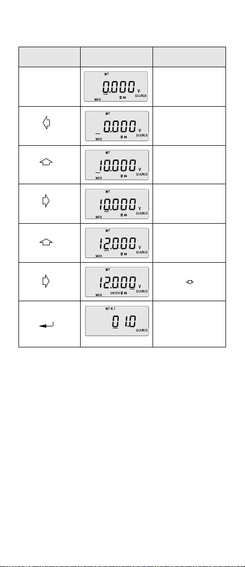
Example of Entries
Entering the upper interval limit (MAX) = 12 V in the basic function, "V, mV
SOURCE" in the range 0...15 V under the output method "Intervals" (INT).
See also Section 4.2.
Key Operation Display Notes
Various key operations
see Section 4.2
Ready for entering
the MAX value;
Cursor and MAX are
flashing
Cursor to the left;
Further movement to the left
causes a jump back to entering
the MIN value
Further incrementing would set
the value to the upper range
limit of 15 V after a short tone
Moving the cursor to the right
MAX set to 12 V
2x
Key (2) now has the function
3x
of ENTER.
Pressing key would set
the value to 11.999 V
Ready for entering the number
N of intervals
"N?" flashe s
3.6 Non-Volatile Saving of Menu Positions and Configurations
The METRAHit 18Cis fitted with a non-volatile memory (NVRAM) in which current
menu positions (LAST MENU) and configurations remain saved after switching off.
When switched off, the NVRAM is supplied with power from 3 small batteries.
During a battery replacement in accordance with Section 7.1, a special supporting capacitor acts in a bridging function for 3 minutes.
As mentioned in Section 2, the instrument will, when switched on again, resume
exactly the last menu position prior to switching off, provided the functions selector position has remained unchanged. This saves time-consuming key operations
for entering complex menus. Furthermore when used on site, this will
reduce the load on the batteries, when the instrument is switched
off whenever it is not in active use.
In all basic functions, the configurations once set for a range or type of sensor, will
be saved in the non-volatile memory when the instrument is switched off, e.g.
MIN/MAX values in INT, RAMP, RAMP timing.
14 GOSSEN-METRAWATT
Page 15

4 Types of Output Signals
4.1 Menu Structure
The methods of outputting signals described in Section 4.2 to Section 4.5 apply to
all basic functions that can be selected with the functions selector (6), except the
basic function ” “. Figure 4 shows their menu structure.
Range or
Bereich oder
Sensortyp 1
Sensor 1
Esc
NUM
2.000 V
Esc
weiter nach
Continue as
in Sect. 4.2
Kap. 4.2
1)
1)
Bei Betriebsart "˚C " und " ˚C "erfolgen zwischen den beiden Menüebenen zusätzliche
Additional entries in accordance with Sect. 5.3 and 5.4 are made
Eingaben gemäß Kap. 5.3 und 5.4
between the two menu levels in the operational modes „°C “ and „°C “
Range or
Bereich oder
Sensortyp 2
Sensor 2
INT
weiter nach
Continue as
in Sect. 4.3
Kap. 4.3
Range or
Bereich oder
Sensortyp A
Sensor A
Esc
Esc
RAMP
weiter nach
Continue as
in Sect. 4.4
Kap. 4.4
Esc
MEM
wie ab Bereich
As from range
ab NVRAM
weiter nach
Kap. 4.5
Esc
oder Sensortyp 1)
or Sensor Type
from NVRAM
Esc
Continue as
in Sect. 4.5
Figure 4 Menu Structure
4.2 Numerical or Manual Entries for the Output Signal (NUM)
The most simple method for outputting signals is by a numerical or manual entry
of the output signal value.
After the range or type of sensor and possible additional entries for ”°C“ have
been selected, the key ” “ (2) must be pressed again when the symbol NUM
appears.
The value 0 or the lowest possible signal value will appear on the number field (1),
and the cursor flashes for further digit settings.
The signal value can be modified within limits in accordance with Section 3.5, and
the displayed value will immediately be present at the jacks (8).
Holding the key (3) or (4) pressed will cause a change of the signal
value regularly by 1 every 0.4 seconds left of the cursor position in small to large
steps up or down depending on the cursor position.
1)
4.3 Intervals, Output in N Steps (INT)
This output method permits subdividing a range into N intervals. This is particularly useful for controlling items under test with digitally or linearly divided analog
displays.
The range limits of standard signals 0 ... 10 V and 0/4 ... 20 mA are fixed. In
other ranges, they can be entered within the whole range.
The number of steps can be set from 1 ... 99.9 (steps), i.e. non-integer steps can
be set. This useful in the particular case when analog displays or recorders with
non-standard full-scale values are connected.
The steps can be triggered manually (MAN) using the keys (3) and (4),
or automatically (AUT) with a dwell time per step that can be selected.
Figs. 5 and 6 show 2 examples of such range divisions.
GOSSEN-METRAWATT 15
Page 16

Betriebsart "˚C, " TC J
Operational mode “°C, ,” TC J
˚C
MAX =
450
350
250
150
MIN =
50
N = 4
Betriebsart "mA ", 4 ... 20 mA
Operational mode “mA “, 4 ... 20m A
mA
20
MAX =
19
14
9
4
MIN =
Scale [bar]
Skala [bar]
N = 3.2
6.4
6
4
2
0
Figure 5 Range Divisions N = 4 Figure 6 Range Divisions
N= 3.2
The MIN/MAX limits in Figure 5 have been entered to cover the whole range
from –200 to + 1200 °C. The range divisions into 3.2 intervals for connection of
an item under test with a scale of 0 ... 6.4 bar, corresponding to a range of
4 ... 20 mA with fixed range limits, is shown in Figure 6. Figure 7 shows the general menu struct. starting with the menu pos. in accordance with Figure 4 in
which the output method 'Intervals' (INT) is ready for a selection.
INT
Esc
Eingabe von Bereichs-
Entering the lower
untergrenze MIN mit
range limit MIN with
und
+
(MIN blinkend)
(MIN flashes)
*
Entering the up per
range limit MAX with
Entering a number of
Eingabe von Anzahl Inter-
intervals N (0–99.9) with
vallen N (0 - 99.9) mit
manuell (INT MAN)
Eingabe von Bereichs-
obergrenze MAX mit
+
und
(MAX flashes)
(MAX blinkend)
+
und
(N? flashes)
(N? blinkend)
Interval step
Intervallschritt
manual (INT MAN)
Esc
Esc
Esc
Entering MIN/MAX is omitted
*
Bei Normbereichen 0...10 V, 0/4..20 mA
in the stan dard ranges
entfällt MIN-/MAX-Eingabe
0 ...10 V, 0/4 ... 20 mA
Interval step
Intervallschritt
automatic (INT AUT)
automatisch (INT AUT)
Esc
Running through MIN-
Durchlaufen des
MIN-/MAX-Bereichs in
MAX range in
N Stufen mit
N steps with
according to Fig. 8
nach Fig. 8
Figure 7 General Operator Control Structure in the Output
Method 'Intervals' (INT)
Enter the dwell time per
Eingabe der Zeit pro Stufe
step fr. 1 s to 60 min with
von 1 s bis 60 min mit
Periodic run through
Periodisches Durchlaufen
the MIN/MAX range in
des MIN-/MAX-Bereichs in
N steps, start/stop with
N-Stufen, Start/Stop mit
und
+
(< flashes)
( blinkend)
acc. to Fig 9
nach Fig. 9
Esc
Esc
16 GOSSEN-METRAWATT
Page 17

Manual Run through the MIN/MAX Range in N Steps (INT, MAN)
The steps can be triggered with the keys (3) and (4) after all parameters in accordance with the menu structure in Figure 7 for the output method
INT, MAN have been entered.
The relationship between the output signal and the key operations can be derived
from the two examples shown in Figure 8 and Figure 9.
Example: Basic function „V, mV“ range 0-15 V, MIN = 2 V, MAX = 10 V, N = 3
Ausgabe (V)
Output (V) Output (V)
MAX = 10
7.33
4.67
MIN = 2
Taste
Key
Ausgangslage
Start position
MAX = 10
MIN = 2
Ausgabe (V)
7.33
4.67
Figure 8 Figure 9
Automatic Run through the MIN/MAX Range in N Steps (INT, AUT)
The automatic run through a programmed range is particularly useful in all cases
in which the feed for a signal circuit and reading on the periphery equipment to be
tested are spatially separated.
The interval time per step over the range from 1 second to 60 minutes can be
entered after the menu "INT AUT" has been selected, and the step sequence can
be stopped by means of the keys (3) and (4) in accordance with
Figure 10.
Example: Basic function „V, mV“, range 0-15 V, MIN = 2 V, MAX = 10 V, N = 3
10
15
time per step = 5 s
t1+t2 = 5 s
t1
25
20
oder
or
t2
Esc
4) 5)
MAX = 10
7.33
4.67
MIN = 2
Keys
Tasten
Legend
Legende
Output (V)
Ausgabe (v)
0
5
0
2) 3)
1)
Figure 10 Example of a Step Function Sequence
Legend:
1) Starting position after the time per step = 5 s has been entered.
The output signal is 2 V.
2) Start of the steps with ” “from 2 V at the bottom upwards.
When using ” “, the starting point is 10 V at the top downwards.
3) Stop with ” “ or ” “,
The time t1 elapsed since the last step remains saved.
4) Continue upwards with ” “ after t2 = 5 s – t1
5) Abort the step function with "Esc" and jump back to the entry of a new inter-
val dwell time. The output signal is approx. 0 V.
The following information on the current status is available during the run through
the step function:
• Flashing segment or in the first digit from the left.
signifies the next step upwards,
signifies the next step downwards
This auxiliary indication is not possible when the first position is already claimed
by a figure > 0, e.g 10.000 V.
• Using the key ” “ (2) causes the residual time to the next step to appear
instead of the current numeric output value.
This residual time is switched off by pressing the key ” “ (2) again.
GOSSEN-METRAWATT 17
Page 18

4.4 Output as Periodic Ramp (RAMP)
Ramp-shaped signals permit checking the time-dynamic behavior of items under
test or of whole measured circuits. One example is the behavior of a control circuit
when the nom. value is entered via the analog nom. value input of the controller.
The instrument can, in this output method, replace expensive hardware and software solutions for long duration test assemblies with cyclic sequences.
The input parameters for the periodic ramp shown in Figure 11 are:
• Lower (MIN) and upper (MAX) range limits that are fixed for the standard range.
0 ... 10 V and 0/4 ... 20 mA, but are otherwise selectable within the whole
range
• Rise and decay time t1 that can be selected between 1 second and 60 minutes
• Dwell time t2 at the upper and lower range limit, and selectable between 0 and
60 minutes
Output
Ausgabe
MAX
MIN
t1
t2 t2t1
Figure 11 Example of a Periodic Ramp
Figure 12 shows the menu structure for entering ramp parameters after the
method of output RAMP (see Figure 4) has been selected.
RAMP
Esc
Eingabe von Bereichs-
Entering the lower range
untergrenze MIN mit
limit MIN with
und
+
(MIN blinkend)
(MIN flashes)
*
Entering the upper range
limit MAX with
Eingabe von Bereichsobergrenze MAX mit
und
+
(MAX blinkend)
(MAX flashes)
Esc
Entering MIN/MA X is omitted
*
Bei Normbereichen 0...10 V, 0/4..20 mA
in the stan dard ranges
entfällt MIN-/MAX-Eingabe
0 ... 10 V, 0/4 ... 20m A
t
Esc
Eingabe der
Entering the
Anstiegs-/Abfallzeit t1 mit
rise/decay time t1 with
und
+
( blinkend)
(< flashes)
Esc
Eingabe der Verweilzeit t2 mit
Enter dwell time t2 with
+
und
( blinkend)
flashes)
Esc
Starting and stopping
Start und Stop der Rampen mit
the ramps with
Figure 12 Menu Structure for Entering Ramp Parameters
18 GOSSEN-METRAWATT
Page 19

When all ramp parameters have been entered in accordance with the menu structure in Figure 12, the ramp is started and stopped with the keys (3) and
(4).
+
Press "Esc" to jump back to entering a dwell time t2.
The output signal is approx. 0 V.
The following information relating to the current status will be available during the
run along the ramp:
• Flashing segments , , or signify:
• Key ” “ (2) causes the residual time to the end of the ramp or the residual
Note!
Interruptions of periodic ramp cycles caused by pressing the
or the key should be avoided.
Uncontrolled sudden changes may otherwise result.
or , ramp running up or down
or , dwelling at the upper (MAX) or lower (MIN) limit.
This auxiliary indication is not possible when the first position is already
claimed by a digit > 0, e.g. 20.000 mA.
dwell time to the start of the next ramp to be displayed instead of the current
numerical output value. This display of the residual time can be switched off
with the key ” “.
Attention!
For reasons of a critical timing, the internal supervisory facilities
described in Section 5.1 (e.g. output load too high) are inactive during the ramp sequence with t1 = 10 s. Hence, error conditions will
in such cases be displayed with a delay until after the end of the
ramp has been reached.
GOSSEN-METRAWATT 19
Page 20

4.5 Output from the Non-Volatile Memory (MEM)
This output method permits entering manually up to 10 signal values or sensor
types, and calling up the values stored in the non-volatile memory. This provides
the possibility of storing measurement series having non-linear intervals. This can
be very helpful when simulating sensors or transducers for various physical and
chemical quantities.
The menu structure shown in Figure 13 from the selection of the type of output
MEM onwards is split into one type of output in which the value is only called up,
and a second type of output in which the value is called up and can be modified.
MEM
MEM
from NVRAM
ab NVRAM
Esc
Output only
Nur Ausgabe
(MEM OUT)
(MEM OUT)
Output of stored values
Ausgabe Speicherwerte
0....9 mit
0 ... 9 with
Esc
Output and input
Aus- und Eingabe
(MEM OUT IN)
(MEM OUT IN)
Selectin g memory No. wi th
Wahl der Speicher-Nr. mit
Output and modification
Ausgabe und Veränderung
der Speicherwerte mit
of memory v alues with
und
+
Esc
Figure 13 Menu Structure from the Method of Output (MEM)
Onwards
The detailed key operations can be copied from the following examples of entering operations.
20 GOSSEN-METRAWATT
Page 21

Example: Basic Function „V, mV“, Range 0...10 V.
Key Operation Display Notes
Ready for output method MEM
1x , 3x
Esc
MEM, OUT, only outputting
possible
Memory No. 0 (small segment
digit left) comprises the value
5 V, available immediately at
the jacks. Memory No. a nd
Keys and can be used
3x
Esc
Esc
to call up other mem. numbers
in steps, and their values are
immediately available at the
jacks
Back to menu selection
MEM OUT for the purpose
of changing to MEM OUT IN,
outputting and entering
(values can be modified)
Ready for output
MEM OUT IN
memory No. that is to be output
or modified.
are flashing.
can be used to select the
The value 2.5 V in memory
No. 3 is available at the jacks
and can be modified.
The value in memory No. 3 has
,3x
been modified to 3.5 V and is
saved with ( )
can be used to select a
new memory No. for outputting
and modification.
GOSSEN-METRAWATT 21
Page 22

4.6 Output by Procedures Saved in the Non-Volatile Memory
This output method permits saving in the non-volatile memory repetitive
sequences during a simulation of process signals such as those occurring e.g.
during periodic checking or during the validation of systems. 10 procedures with
up to 99 program steps each (records) are available for saving such sequences.
The program steps within a procedure can be selected freely via basic functions,
ranges and output methods.
The PC software „METRAwin 90“ is offered as an ancillary program with an interface adapter for transferring a procedure from the PC to the instrument, so that
procedures can be created.
Working with procedures is explained by way of examples in the following
sequences.
Keys,
Functions selector (6)
and
simultaneously for at
least 1 second
3x
2x
Functions selector (6) is
already in position ”V, mV“
Display Notes
Change to "Procedures"
from any menu position.
Ready for selecting
procedure No. 1.
No procedure stored
under No. 4.
Selecting procedure No. 2
with 10 records.
1 record in procedure No. 2 =
output of 2.5 V DC.
Small digit on the left (13) =
procedure No.
Briefly displaying the next
record No.
Subsequently
New basic function „°C „ is
displayed flashing when t his
does not comply with the position of the functions selector
Function selector (6)
in basic function
„°C „
9x
and
simultaneously
Record No. 2 = output thermocouple type K, 1200 C with the
internal reference temperature
("0" top right). Key leads
back to record No. 1
End" is signalled shortly after
the last record No. 10.
Subsequently
Ready for entering procedure
No. 3 or selection of a different
procedure No.
Switching the output off via procedures, and jump to the highest menu level of the set basic
function.
22 GOSSEN-METRAWATT
Page 23

+
Note!
When switching off, output method "Procedures" remains saved in
the non-volatile memory , i.e. the last menu position is set when the
instrument is again switched on. This results in a battery-saving
operation during location changes on sites.
Consequently, switching this basic function off is possible only like
switching on via the keys “ “ (3) and “ “ (4) pressed
simultaneously for at least 1 second.
The display of "REMOTE MAN" is an acknowledgement that the output method "Procedures" is set.
4.7 Output via the Serial Interface (REMOTE)
The calibrator in its standard version is fitted with infrared diodes permitting communicating with a PC via a DC-decoupled connection with an interface adapter.
This adapter in conjunction with an efficient "Windows" communication software
„METRAwin 90“, covering many valuable applications, is offered as a cost efficient ancillary item.
Switching the Interface On
➭ When pressing the keys "ON/OFF" (2) and ” “ (3) simultaneously, oper-
ation via the interface will be acknowledged with the symbol "REMOTE" (16).
At the same time, an automatic switching off of the equipment will be inhibited,
and this is indicated by the symbol ” “ (18).
For this reason, the plug type mains supply should be used for long operational
periods. This avoids an automatic switching off by the battery supervisory circuit.
Operating Controls in REMOTE Operation
The instrument will not respond to any key operation when set to REMOTE operation. One exception is given by switching off the equipment with the ”ON/OFF“ key
(2). Only by switching the instrument on with this key will cause it to resume local
control operation.
LC Display in REMOTE Operation
The instructions sent by the PC during direct operation will be executed by the
instrument directly, provided the basic function set by the message complies with
that set on the functions selector (6). The LC display will acknowledge the programmed signal value and the output method after each message.
Wrong settings of the functions selector
are signalled by a flashing display of the
scheduled basic function. The new
instruction will be executed immediately
when the functions selector (6) has been
set to the scheduled basic function.
Scheduled basic function
Message Read-Out during
Current Measurements in the LOCAL Operating Mode
In this operating mode a message with the measurement value in ASCII format is
transmitted via the serial interface with a frequency of approximately 6 measurements per second. The format corresponds to the LCD, e.g. „17.35 mA“.
If overload occurs, the message is expanded via “overrange” to include the content: “24.00mA”.
Interface parameters are as follows:
Format: 8 data bits, no parity, 1 stop bit
Baud rate: 9600 baud
GOSSEN-METRAWATT 23
Page 24

Signal LED on the Interface Adapter
One green and one red signal diode on the interface adapter indicate the following
information and warning:
• Green LED:
This will be lit briefly when instructions are transferred from the PC to the
instrument.
• Red LED:
This will be lit during the transfer of messages from the instrument to the PC.
This occurs after each switching on and when a message received from the PC
is acknowledged. This response, as well as a signalling tone, give a confirmation indicating a correct physical communication between PC and instrument.
24 GOSSEN-METRAWATT
Page 25

5 Basic Functions
5.1 General Notes
The 7 basic functions that can be set manually with the functions selector (6),
form the highest menu level in the instrument. However, a signal output within the
set basic function occurs only after the signal range or the sensor type, and the
output method have been selected, and further key operat. have been executed.
In all menu positions in which the output signal is not defined, e.g. parameter
entries, the output signal will be set to the following symbols:
• approx. 0 V in”V, mV“, ” “, ”°C “, ”mA “ and ”mA “,
as well as
• approx. 100
Similar values will also be present at the jacks when a jump back into a higher
menu position is executed by using the "Esc" key (5). The jacks are open-circuited
in all intermediate positions of the functions selector, i.e. they are not connected
internally with the circuit.
➭ The lowest possible range for the output signals to be simulated on the
uppermost menu level should always be selected in the basic functions ”V,
mV“, ”mA “ and ”mA “. This produces the best possible accuracy,
and the
battery drain will be lower.
W in ”°C “ and ”W“.
5.2 Supervisory Circuits
Various internal measurement and supervisory circuits are continuously testing
the external and internal conditions of the instrument under which the selected
output signal available at the jacks is within the technical specifications.
These are:
• Measurement of the Battery Voltage
This leads to an LC display with the symbol ” “ (19) when the voltage has
dropped below approx. 3.4 V, and switches the instrument off when the voltage
drops further below approx. 3.2 V.
The battery voltage measurement has the additional purpose of compensating
the effect from the battery voltage on the accuracy of the instrument.
+
Note!
The load is heavier when the load current and voltage is high as well
as in the voltage range 0 ... 10 V or 0 ... 15 V respectively. This can
lead to an immediate internal cut-out when the batteries are weak
or used at the end of their useful life.
• Measurement of the Output Load in the Basic Functions „V, mV“ and „TC, “
The illustrated flashing warning
display ”ERROR MAX LOAD“ will
appear above a current drain of
approx. 15 mA
Above approx. 18 mA, the flashing
display of ”ERROR OUT MAX LOAD“
indicates that the stabilization in the
instrument is no longer ensured.
This error message will also appear during a short-circuit on the jacks with the
following exception:
The current state makes a detection of a short-circuit impossible
with a nominal output voltage of approx. 4 mV and within approx.
0.7 to 2.5 V.
GOSSEN-METRAWATT 25
Page 26

• Measurement of the Sensor Current in the Basic Functions „°C “ and „W“
A correct electronic resistance simulation depends on the magnitude of the
sensor current (from the item under test) and its polarity.
The operating range for current is Is = 0.05 ... 0.1 ... 1
The specified tolerance applies to Is = 0.1 ... 1 mA
Twice the tolerance applies to Is = 0.05 ... 0.1 mA and 1 ... 1.4 mA
Sensor current outside the permissible range is indicated by the following
error messages:
Is < 0.05 mA, but > 0.015 mA
„ERROR MIN“
Is < 0.015 mA,
Input open-circuit or wrong polarity.
„ERROR OUT MIN POL.“
Is > 1.4 mA
„ERROR OUT MAX“
When these described warning messages appear, the resistance simulation
will continue to function, but without reliable accuracy.
In such cases, additional means should be employed (e.g. selected precision
resistors) to ensure an operational usefulness in principle, and an accuracy
required for practical applications
• Supervision of the Current Regulation and the Actual Current in the Basic
Function “ “
The regulating circuit for the internal current source is supervised.
A deviation of nominal/actual values due to too high an output load will trigger
the display of an error. This supervision of the regulating circuit is also used for
a switching action from a low auxiliary voltage, normally used for reducing the
battery drain, to a higher voltage as a function of the external load.
The current source normally works with an internal auxiliary voltage that allows
a voltage drop of 4 V max. across the external load. Exceeding this voltage
drop will
– either cause a change to a higher auxiliary voltage for a voltage drop up to
15 V (20 mA x 750
– or trigger the display of an error message without switching the auxiliary
voltage, when the external load is above approx. 5 k
broken.
The internally switched auxiliary voltage is indicated at the top edge of the LC
display (* in the example illustrations) by a "0" for a low auxiliary voltage, or a
"1" for a high auxiliary voltage.
W) when the external load drops below approx. 5 kW .
... 1.4 mA
W or when the circuit is
The following examples of sequences show the various LC displays as a function of the external load.
26 GOSSEN-METRAWATT
Page 27

1st Example: Range 4 ... 20 mA, external ´load = 1 kW
Process Display
Nominal value 4 mA,
Ua = 4 mA x 1 k
= 0 = low auxiliary voltage
*
W = 4 V
*
Increase to 5 mA, i.e. Ua > 4 V
With a brief display of
”ERROR MAX burd“ a change to
a higher auxiliary voltage is made
= 1
*
Increase to 20 mA, i.e. Ua > 15 V
The nominal/actual value deviation
triggers the error display
”burd“ = load too heavy
Note: When switching from a higher auxiliary voltage back to a lower one, the
signal output must be aborted to go to a higher menu level using "Esc" (5) or a
change at the functions selector is necessary, even when Ua
2nd Example: Range 4 ... 20 mA, external load = 0
Process Display
Nominal value 4 mA,
Ua = 0 V
= 0 = low auxiliary voltage
*
The circuit will be broken.
The measurement of the actual value
finds Ra > approx. 5 k
Hence ”ERROR OUT MAX burd“.
The auxiliary voltage is not increased,
because a fault has been detected in
the output circuit.
The error message disappears when the circuit is closed.
• Supervision of the Current Regulation in the Basic Function „ “
A nominal/actual deviation in the basic function ” “ can occur when the
external signal circuit does either not exhibit the programmed nominal current
or when the voltage on the jacks is too low.
These fault conditions are pointed out by the following displays:
The actual current is less than the
value set on the instrument, but higher
than approx 1 mA.
Reason: Current limiting in the ext.
circuit or the voltage is too low.
The actual current is less than the
value set on the instrument, but lower
than approx 1 mA.
Reason: Current limiting in the ext.
circuit or the voltage is too low.
W .
£ 4 V.
W
*
*
GOSSEN-METRAWATT 27
Page 28

5.3 [V, mV], Voltage Source
➭ Set the functions selector (6) to "V, mV"
➭ Connect the item under test in accordance with Figure 14 using test leads.
Once the instrument is switched on, the
4 signal ranges 0-10 / 15 / 1.5 V /
150 mV on the uppermost menu leve
will be available for selection, and the
wanted signals can be simulated in the 4
output methods NUM, INT, RAMP, and
MEM.
The first range 0-10 V applies as a standard signal in process techniques.
In this range, MIN/MAX entries are not
required under output methods INT and
RAMP. These are fixed at MIN = 0 V and
MAX = 10 V. The output of the instrument is protected against short-circuits,
and loads with more than approx. 15 mA
or approx. 18mA respectively are
detected and displayed by the internal
supervision in accordance with Section
V, mV
+
–
V
5.2. The short-circuit current is
approx. 23 mA.
Figure 14 Connections for Use
as a Voltage Source
5.4 , Pulse Generator
Description of the Function, Applications
This basic function is designed for typical requirements in processing techniques,
such as e.g. simulation of initiators, pulses from flow counters, rev-counters,
energy or frequency control and event counters in the low frequency region. The
maximum pulse amplitude of 15 V is usually adequate, even for inputting pulses
into control circuits (SPS) using 24 V logic inputs.
The instrument produces positive square waves with a pulse duty factor of 1:1
(duty cycle 50 %). The output can be selected as continuous or as a time-limited
number of pulses.
°C
Menu Structure
Figure 15 on the following page shows the menu structure which deviates from
the basic scheme of the other basic functions.
The input parameters are: amplitude, frequency, and a selected number of positive (LO-HI) or negative (HI-LO) pulses.
28 GOSSEN-METRAWATT
Page 29

1)
Esc
2)
Esc
3)
Esc
4) 5)
Esc Esc
6) 7)
Figure 15 Menu Structure for the Pulse Generator
Legend for the individual menu positions in Figure 15
1) Selection of the basic function ” ” makes the frequency range
of 0.01 ... 999.99 Hz available
2) Entering an amplitude of 0 ... 15 V
3) Entering a frequency of 0.01 ... 999.99 Hz
4) Selecting continuous pulse output
5) Selecting an output of N pulses at a prescribe pulse frequency
6) Continuous pulse output with 502.05 Hz
Stopping the pulse output with ” “
Note:
The nearest possible frequency for nominal value entry is calculated from
the limited timer resolution of the microprocessor.
7) Entering the number of pulses
Esc
8) 9)
Esc Esc
10)
11)
10)
11)
GOSSEN-METRAWATT 29
Page 30

8) The pulse output starts with
U
a low level in accordance with the
upper timing diagram in Figure 16.
9) The pulse output starts with a high
level in accordance with the lower
timing diagram in Figure 16.
U
N
t
" " = Start
N
t
Figure 16 Timing Diagram
10) Output of the pulse series with the selected parameters and the nearest
possible frequency in accordance with menu position 6).
After the output of the pulses, the instrument is ready for a new start from
menu positions 8) or 9).
11) Pressing the ” “ key (2) will cause the display for approx. 1 second of
the number of pulses remaining at the time of pressing that key, instead of
the frequency.
+
Note!
This change-over will lead to a short duration break in the pulse output at the jacks (only noticeable at higher frequencies).
Operator Control
➭ Set the functions selector (6) to „ “.
➭ Connect the item under test by means of test leads as shown in Figure 17.
➭ Continue with further settings in accordance with the menu structure
described above.
+
–
t/min
Rpm
Upm
Figure 17 Connection of the
Tes t Lea ds
Attention!
For reasons of a critical timing, the automatic cut-out and supervision of the battery voltage as well as of the loading are switched off
during the output of pulses. However, the output is protected
against short-circuits, and the output current is limited to
approx. 25 mA.
30 GOSSEN-METRAWATT
Page 31

5.5 “°C “, Thermocouple Simulation
Description of the Function, Applications
10 types of thermocouple are available for selection and can be simulated over
the full temperature range specified by IEC/DIN.
The internally measured reference temperature can be used or the temperature of
an external reference for –50 to +100 °C can be entered.
Important Advice relating to the Reference Temperature
The internal reference temperature is continuously measured by using a built-in
temperature sensor coupled with the jack ” “ (8).
The reference temperature for Items under test having a thermocouple measurement input terminal is usually measured at the terminals for the thermocouple.
The two measurements may differ from each other, and the difference fully enters
the simulation as an error. The following methods will help to reduce this error:
• The connections from the item under test to the jacks of the instrument
are made with a compensating lead for the thermocouple to be simulated
(Figure 18).
• The temperature is measured with a precision temperature measuring instrument at the thermocouple terminals of the item under test, and this value is
entered into the instrument as an external reference temperature (Figure 19).
The connection between the calibrator and the measuring instrument is made
by using copper leads.
Entering the external reference temperature is also used in all cases in which the
temperature measurement in the item under test is carried out via a reference
point with a stabilized temperature (end of the compensating lead for the thermocouple).
Item
under
test
Compensating lead,
e.g. NICr/NiAl for type K
Item under test
Temperature
measurement instrument
Copper lead
Terminal block
for temperature
at the terminals
Figure 18 Temp. measure-
ment via comp. lead
Figure 19 Entering the refer-
ence temperature
Operator Control
➭ Set the functions selector (6) to
°C “
„
➭ Select the wanted thermocouple type
using the keys ” “ (3) or” “
(4) . For an accurate designation and
ranges see Section 6.
°C
➭ The internal reference temperature
will be displayed after entering this
with the ” “ key (2). The choice
between internal or external reference
is explained further down by an application example.
➭ Connect the item under test to the
jacks in accordance with Figure 20,
–
Compensating
lead when using an
internal ref. temperature
+
and note the advice given above for
the reference temperature in respect
of the connecting leads.
°C
Figure 20 Connections of the
measurement Leads
GOSSEN-METRAWATT 31
Page 32

Example for Inputting a Specified Reference Temperature
Key Operation Display Notes
After switching ON or
adding the connection
using the functions
selector (6)
, 2x
, 5x
1)
1)
Ready for selecting the type of
thermocouple
Display of the internally measured reference temperature
1) I = internal ref. temperature
2) 0 = pointing out the int. ref.
temp. in other menu positions
2)
Selecting the internal reference temperature for the following simulations
2)
Numerical change of the value
= entering an external ref.
temp.
1) E = external ref. temperature
2) 1 = pointing out the ext. ref.
temp. in other menu positions
2)
Selecting the external reference temperature 20°C for the
following simulations.
2)
Notes!
• A change from °C to °F may be made by keeping the keys ” “ (4) and
” “ (2) pressed simultaneously when switching on the instrument.
• The output load is supervised, and an output current of approx. 15 mA is signalled by a flashing display of ”ERROR MAX LOAd“ or in the case of approx.
18 mA it is signalled by ”ERROR OUT MAX LOAd“.
The output is protected against short-circuits. The short-circuit current is
approx. 23 mA.
• In the case of low-impedance items under test, e.g. moving coil meters or
recorders, a signal distortion by the output resistance R
W max.) can lead to significant errors.
DU = I
(Error
x Ra, e.g. 1 mV with I
out
= 5 mA, Ra = 0.2)
out
of the equipment (0.2
a
32 GOSSEN-METRAWATT
Page 33

5.6 “[°C] “, RTD Sensor Simulation
Function and Applications
The electronic resistance simulation is, in principle, a measurement of the sensor
current Is, that is fed by the item under test into the instrument, and a voltage U
depending the programmed resistance R
applies to the voltage: U
This simulation operates within limited ranges for sensor current and resistance
that are aimed at a simulation of commonly used RTD temperature sensors. How-
= Rp x I
a
ever for this range of application, the electronic simulation realized in the instrument, offers a flexibility of the signal output that is far superior to conventional
resistance sources.
Operator Controls
➭ Set the Functions selector (6) to ”°C “
➭ Set the wanted type of RTD sensor using the keys ” “ (3) or ” “ (4).
Their temperature ranges are stated in Section 6.
➭ The lead resistance ROFFS (Roffset) is displayed after entering the above with
the ” “ key (2). Entering between –9.99 and +99.99
resistance is added to the later programmed resistance value in accordance
with the sensor characteristic. The value can be modified or a jump to the type
of output can be made by twice pressing key (2) (” “ and ” “).
➭ Connect the item under test with the
jacks in accordance with Figure 21 and
observe the following notes relating to
sensor current supervision which is additionally described in detail in Section 5.2.
1)
Sensor cables for 4-wire connection
Note Relating to Sensor Current Supervision
When items under test with unknown sensor current are connected and/or the polarity of the sensor current is not marked at t he point of connection, error messages can
be generated at the output that can be interpreted in the following manner:
„ERROR OUT MIN POL.“
The item under test does not supply a
sensor current (<10
connected with the wrong polarity. The
mA) or the sensor is
polarity must be reversed and the item
under test must be measured separately
when this is unsuccessful.
„ERROR MIN“
The sensor current is too low (<50
Resistance simulation will operate, but
compliance with the specified limit is not
ensured.
„ERROR OUT MAX“
The sensor current is too high (>1.4 mA).
Resistance simulation will operate up to
approx. 2 mA, but compliance with the
specified limit is not ensured.
Note the tolerance figures in Section 5.2 that are dependent on the
sensor current !
is applied to the jacks, the following
p
s
W is possible. This
°C
I
1)
S
+
°C
Figure 21 Connection of the
Measurement Leads
mA).
1)
–
a
GOSSEN-METRAWATT 33
Page 34

5.7 ”W“, Resistance Simulation
This basic function differs from ”°C “ only in the fact that a resistance value
within the range 30.0
Hence:
➭ Set the functions selector (6) to ”
➭ Take further information for operator control from Section 5.6 relating to the
basic function " C ", simulation of RTD sensors.
W to 2000.0 W is entered directly and can be simulated.
W“.
+
Note!
Simulation will also work below 30 W to 0 W . However,
the data in respect of inherent deviation of the instrument are not ensured.
5.8 “ “, Current Source
➭ Set the function selector to ” “
➭ Connect the item under test by
means of the measurements accordance with Figure 22.
3 signal ranges 4-20 / 0-20 / 0-24 mA
are available for selection after the
instrument has been switched on, and
signals in the 4 methods of output NUM,
INT, RAMP and MEM can be simulated in
these ranges.
Figure 22Connection of the
The first two ranges apply as standard signals to process techniques. No entries
of the MIN/MAX limits are required for the output methods INT and RAMP,
because these are fixed to MIN = 4 or 0 mA respectively and MAX = 20 mA.
A supervision of a correct current regulation and a two-stage matching of the
internal auxiliary voltage to the load by the external circuit is carried out during the
output of current.
For this reason, please read the detailed description of this supervision in
Section 5.2 , and check the external circuit when error messages described there
are displayed.
Note:
The little figure 6) at the top left on the LC display signifies:
0 Low battery drain reducing auxiliary voltage for external loads up to 200
at 20 mA
1 Higher auxiliary voltage for external loads up to 750
The switching from a low to a high auxiliary voltage is carried out
when the voltage at the jacks exceeds approx. 4 V.
+
–
%
Measurement Leads
W at 20 mA
W
34 GOSSEN-METRAWATT
Page 35

5.9 Current Measurement [mA]
Functions Description
Two basic functions are possible in the “mA “ selector switch position:
• Current measurement (basic function: MEAS)
• Active current control (basic function: SINK, see Section 5.10).
The measurement input for the MEAS function is unipolar and encompasses a
current measuring range of 0 ... 24 mA DC.
Operation
➭ Set the function selector
switch (6) to “ “.
➭ Complete the circuit with
correct polarity (+ to
““).
➭ Activate the “ “ key
(2); input current is displayed
at the instrument.
+^
Periphery
Voltage
Source
+
+
–
–
+
Figure 23 Measurement Cable
Note!
Current measurement includes unipolar display only. “0” appears at
the display if polarity is reversed, and the power circuit is disabled
by a diode.
Connection
Attention!
Input currents of greater than 24 mA are limited by the instrument
to 24.00 mA by means of a semiconductor; entry into the upper
limit range is indicated by blinking characters at the display and the
MAX menu guidance symbol.
The voltage drop from the external circuit caused at the jacks in the
event of an overload may not exceed 27 V DC.
GOSSEN-METRAWATT 35
Page 36

5.10 “ “, Current Drain, Simulation of a Transmitter
with two Leads
Description of the Function, Applications
In this basic function, the current selected between 0 and 24 mA flows into the
instrument, independent from the DC voltage (4 ... 27 V) present at the jacks. The
most important application of this function as a current drain is the simulation of
4-terminal transmitters.
4-terminal transmitters are measurement transducers for measuring quantities in
process techniques. In an operation as a drain, they accept a constant current
between 4 - 20 mA depending on the measured quantity and independent from
the applied voltage (Figure 24). The measuring circuit is fed from the signal of
4 - 20 mA. 4-terminal transmitters are particularly useful in systems with long
distances between the components, e.g. on board of ships, in chemical industry
plants or refineries, because additional lines for auxiliary voltages can be omitted
in this case.
Mains
power
supply
24 V
Peripheral equipment
+
–
4 ... 20 mA = 0 ... 100 °C
Figure 24 Example of a Meas. Circuit for 4-Terminal Transmitters
Tests on peripheral equipment by means of simulation of a 4-terminal transmitter
in a measuring circuit are described in the following paragraphs of these operating instructions.
Operator controls
➭ Switch on the instrument.
After the instrument is switched on the
basic function
„“ MEAS. is
active.
➭ Change with the key (3) to the basic
„“ SINK.
function
3 signal ranges 4 - 20 mA, 0 - 20 mA
or 0 - 24 mA are available for the
selection in the same menu level.
After selection of the range the signal can
be simulated in the following 4 output
methods:
NUM, INT, RAMP and MEM.
The first two ranges apply as standard signals to process techniques. No entries
of the MIN/MAX limits are required for the output methods INT and RAMP,
because these are fixed to MIN = 4 or 0 mA respectively and MAX = 20 mA.
Supervision of correct current regulation is carried out in the instrument. For this
reason, please read the detailed description of this supervision in Section 5.2, and
check the connected circuit for the presence and polarity of the specified voltage
when error messages described there are displayed.
4-terminal
transmitters
+
–
–
Mains power unit 27 V max.
+
°C
Sensor
e.g. Pt100
(disconnected)
+
–T
=
+
Peripheral
equipment
(item under test)
Figure 25Connections with Mea-
surement Leads
36 GOSSEN-METRAWATT
Page 37

Notes:
• Verify that the applied voltage does not exceed 27 V. Otherwise, the instrument
will be thermally overloaded.
• The instrument is protected against wrong polarity.
Wrong polarity or missing voltage is indicated by the flashing error message
"ERROR OUT MIN I:U-in".
Warning!
The instrument shall not be used in explosion endangered zones or
inserted in self-protected circuits.
GOSSEN-METRAWATT 37
Page 38

6 Technical Data
Basic Functions
I Source
Fixed Ranges
Standard signal 4 ... 20 mA, 0 ... 20 mA Resolution 1
Variable range 0 ... 24 mA Resolution 1
Ranges are entered into a non-volatile memory by
means of keys.
Maximum Load 200/750
Overload limited by an internal self recovering PTC resistor
W with automatic change-over
(heavier battery drain at 750
for protection
W)
U Source
Fixed range
(Standard signal) 0 V ...10 V Resolution 1 mV
Variable ranges 0 V ... 15 V Resolution 1 mV
0 V ... 1.5000 V Resolution 0.1 mV
0 mV ... 150.00 mV Resolution 0.01mV
Range entry by keys
Load
Output resistance 0.2
³ 1 kW (max. 15 mA at 15 V)
W
RTD source
Sensor Pt 100 Range –180 ... + 850 °C Resolut. 0.1 °C/°F
Pt 1000 Range –180 ... + 250 °C Resolut. 0.1 °C/°F
Ni 100, Ni 1000 Range –60 ... + 180 °C Resolut. 0.1 °C/°F
Operating conditions Sensor current 0.05 ... 0.1 ... 1
... 1.4 mA
Setting °C or °F
Entry of signal offset range – 9.99 ... +99.99
W
(e.g. for power cable resistance)
R Source
Range covered 30 ... 2000.0 W Resolution 0.1 W
Operating conditions Sensor current 0.05 ... 0.1 ... 1
... 1.4 mA
Thermocouples (according to DIN/IEC584)
Thermocouples Ty pe Range Resolution
Fe-CuNi Type J
Fe-CuNi Type L
Cu-CuNi Type T
Cu-CuNi Type U
NiCr-NiAl Type K
NiCr-CuNi Type E
Pt10Rh-Pt Type S
Pt13Rh-Pt Type R
Pt30Rh-Pt6Rh Type B
Nicrosil-Nisil Type N
– 200 ... + 1200°C
– 328 ... + 2192°F
– 200 ... + 900°C
– 328 ... + 1652°F
– 250 ... + 400°C
– 418 ... + 752°F
– 200 ... + 600°C
– 328 ... + 1112°F
– 250 ... + 1350°C
– 418 ... + 2462°F
– 250 ... + 1000°C
– 418 ... + 1832°F
– 50 ... + 1750°C
– 58 ... + 3182°F
– 50 ... + 1750°C
– 58 ... + 3182°F
+ 50 ... + 1800°
+ 122 ... + 3272°F
– 240 ... + 1300°C
– 400 ... + 2372°F
D/A-resolution 3 mV
Setting °C or °F
Reference- temperature internal via a temperature sensor at the terminals
external, entry – 50 ... + 100 °C
38 GOSSEN-METRAWATT
mA
mA
1 °C/°F
1 °C/°F
1 °C/°F
1 °C/°F
1 °C/°F
1 °C/°F
1 °C/°F
1 °C/°F
1 °C/°F
1 °C/°F
Page 39

I Measurement
Measuring Range 0 ... 24 mA unipolar, resolution 0.05 mA
Voltage Drop approx. 0.5 V DC + I (mA) x 125
W
Sampling Rate approx. 6 measurements/sec.
Overload Capacity Input current is limited to 24 mA. Entry into the upper
range limit is signalled.
Max. Input Voltage
±27 V DC
I-Drain (Simulation of 4-Terminal Transmitters)
Fixed ranges
Standard signal 4 ... 20 mA, 0 ... 20 mA Resolution 1
Variable range 0 ... 24 mA Resolution 1
mA
mA
Ranges are entered by means of operator keys.
Input voltage/
Input power 4 ... 27 V, max 0.6 VA
Overload internal self-recovering PTC resistor
Frequency (Squarewave Pulses)
Frequency range 0.01 ... 999.99 Hz Resolution 0.01 Hz
Pulse amplitude selectable 0 ... 15 V
Resolution 1 mV
Duty cycle 50 %
Pulse Series
(as for frequency, but the number of pulses are selected)
Number of pulses 1 ... 99999
Start selected for start from a high or a low level
Output Methods for Source and Drain Functions
Numerical by means of keys
Interval subdivision of a fixed (standard signal)
or a variable range into N intervals
Interval step switched manually or automatically
Dwell time per step programmable over 1 s ... 60 min
Ramp periodic, positive or negative going ramp time
and dwell time
each programmable over 1 s ... 60 min
Memory (10 for each individual values stored in a non-volatile
range and type of sensor) memory can be output in steps
Error limits (for Tu = 23 ± 3°C)
I Measurement 0.25% of the value
I source/drain 0.05 % of the value + 2
±0.05 mA
mA
V source (15 V) 0.05 % of the value + 2 Digit
Thermocouples
ext. ref. temp. 0.1 % of the value
int. ref temp. 0.1 % of the value
Pt 100, Ni 100,
Pt 1000, Ni 1000 0.1 % of the value + 0,25 °C
R source (500
W) 0.1 % of the value + 0,1 W
1)
+ 15 mV
1)
+ 15 mV + 2 °C
2)
2)
Frequency
Frequency stability: 30 ppm
Frequency accuracy 0.05 % of the indicated actual frequency
resolution of the timer frequency, approx. 16
ms,
results in a difference between the nominal and near-
est possible actual frequency
1) relative to the thermocouple voltage [mV];
The errors in [°C] as a function o f thermocouple and temperatu re are listed in a table
shown in the Appendix to these operating instructions
2) for a sensor current 0.1 ... 1 mA
GOSSEN-METRAWATT 39
Page 40

Display 5-digit LCD 12 mm high with additional text
and symbols for user guidance
Operator Controls Setting of the basic functions by means of a rotary
switch for menu selection (range, output) and numeri-
cal entries via 4 menu keys
Auxiliary Energy
Battery operation from 3 small alkaline-manganese cells 1.5 V / 2.2 Ah
type IEC LR6
Useful time approx. 15 h without current drain for V
(with 2.2 Ah per cell) approx. 10 h without current drain for V
approx. 12 h with I source 20 mA/
out
out
£ 200 W
£1.5 V
> 1.5 V
approx. 6 h with I source 20 mA/> 200 to 750 W
Switching off after 10 min by means of an internal timer when no key
or switch is operated
Supervisory circuit Display of low battery voltage and subsequent
switching off
Mains operation Separate plug type mains unit. The inserted battery will
be switched off automatically.
Rechargeable cells The instrument can also be operated with rechargeable
NiCd or NiMH cells charged by a separate charger.
Ambient Conditions
Operational Temperature – 10 ... + 50°C
Storage Temperature – 25 ... + 70°C
Temperature error max 0.05 % of the value per 10°K,
additional offset 2 digits/10°K
Relative humidity max. 75%, no condensation
Climatic class 2z /0/50/70/75 % derived from VDI/VDE 3540
Height over NN up to 2000 m
Electrical Safety (for plug type mains unit) protection class II
to IEC 1010-1/DIN VDE 0411
Mechanical Design
Type of protection IP 50 to VDE 0470 / EN 60529
IP 20 at the jacks for connection an main supply
Dimensions 84 x 185 x 35 mm
Weight approx. 400 gr. including batteries
40 GOSSEN-METRAWATT
Page 41

7 Maintenance
7.1 Batteries
The calibrator is an instrument that, in comparison with a merely indicating handheld multimeter, requires in principle more auxiliary energy and has a correspondingly shorter operational time of the batteries.
In the METRAHit 18C, this has been taken into consideration in several ways:
• By automatically switching off after 10 minutes of operation without action by
means of keys or function selector.
• By enabling, after switching on, a continuation with the function set by the
function selector, provided the latter has not been changed since switching off.
• By the plug type mains unit as a standard accessory that, when used, discon-
nects the inserted batteries.
• This disconnection and the permissible operational range of the battery voltage
of 3.3 to 4.6 V permits using small primary cells (IEC LR6) or 3 rechargeable
NiMH-cells of 1.2 V each. The latter must be charged externally by a separate
plug type charger offered as an accessory.
Before switching the instrument on, as well as during battery replacement or after
storage of the instrument, the user should make sure that the batteries in the
instrument have not leaked.
When batteries have leaked, the user must remove the battery electrolyte completely and insert new batteries, before using the instrument again.
Prior to a long storage of the instrument for more than approx. 2 months, the batteries should be removed to protect the instrument against damage by battery
leakage. This also avoids discharging the batteries by the current flowing for the
non-volatile in the switched off state (current typically 0.1 mA).
The batteries should be replaced as soon as possible when the symbol " "
(18) appears on the display.
The internally measured and supervised battery voltage depends on the magnitude of the load, i.e. an increased load on the output will cause this symbol to
appear earlier, and may even lead to a cut-out by the internal low voltage supervision.
Replacement of Batteries
• Place the instrument face down on a surface, release the two screws on the
back, and lift the lower housing part carefully off by beginning at the bottom
end while holding the twin battery holder so that it can be drawn out from the
compartment in the lower housing part.
The upper and lower part of the housing are engaged at the top end by securing hooks.
• Remove the twin battery holder from the compartment in the upper housing
part without applying mechanical force on the red/black connecting litz wires.
• Remove all 3 inserted batteries from the two battery containers.
• Insert 3 new batteries or recharged accumulators, and observe the polarity
engraved on the battery holders. When the user does not want to loose the
configurations and procedures saved in the non-volatile memory, the instrument may be left without batteries for a maximum of 3 minutes.
• Re-insert the twin battery holder into the compartment of the upper housing
part in accordance with Figure 26, and make sure that the connecting litz wires
are not resting on the housing edge or on the screw with the tapped hole.
GOSSEN-METRAWATT 41
Page 42

Single battery holder on
the printed circuit board
Twin battery holder
Route the litz wire within
the free space
Figure 26 Battery Holders
• Replace the lower housing part by starting at the upper face, and make sure
that the securing hooks at this point are correctly engaging. Make also sure
that the connecting litz wires are not resting on the edge of the housing or on
the screw.
• Secure the lower housing part with the two screws.
• Please dispose of used batteries as hazardous waste !
7.2 Housing
Special maintenance work on the housing is not required. Please ensure that the
surface is kept clean.
42 GOSSEN-METRAWATT
Page 43

8 Appendix
8.1 Errors in [°C] in Thermocouple Simulation
The error for thermocouples is specified in the technical data as a DU-error of the
thermocouple voltage. The
ple characteristic.
DT [°C] = (0.001 × U
The maximum of this ratio is determined within each partial range.
dU/dT is calculated from the difference in voltage for
Examples
1. For a thermocouple type R, the maximum of the ratio in the range
200 - 300 °C is at 200 °C:
DT [°C] = (1.468 + 15) ¸ (1557 - 1468)/10 = (16.468 / 8.9) = 1.85 °C
2. For a thermocouple type K, the maximum of the ratio in the range
400 - 500 °C is at 500 °C:
DT [°C] = (20.640 + 15) ¸ (20640 - 20214)/10 = (35.640 / 42.6) = 0.84 °C
As a result of the linearity of the thermocouple characteristic, that also applies to
its slope (1st derivative dT/dU), the calculated
Table for partial ranges of 100 °C covering all types of thermocouple.
The listed values represent the possible maximum error in the respective partial
range.
Thermocouple
Typ e
Partial Range °C J L T U K E S R B N
– 200 ... 100 1.00 0.80 1.26 1.09 1.30 0.91 – – – 1.79
– 100 ... 0 0.47 0.47 0.64 0.63 0.60 0.44
0 ... 100 0.37 0.37 0.41 0.43 0.46 0.37 2.73 2.78 – 0.60
100 ... 200 0.47 0.46 0.46 0.46 0.58 0.39 2.11 2.06 15.03 0.64
200 ... 300 0.56 0.56 0.52 0.50 0.66 0.46 1.93 1.85 7.23 0.69
300 ... 400 0.67 0.66 0.58 0.58 0.75 0.55 1.90 1.78 4.98 0.76
400 ... 500 0.76 0.75 – 0.64 0.84 0.64 1.94 1.79 3.85 0.83
500 ... 600 0.83 0.82 – 0.70 0.94 0.74 1.98 1.81 3.18 0.92
600 ... 700 0.87 0.87 – – 1.05 0.85 2.01 1.83 2.79 1.01
700 ... 800 0.94 0.91 – – 1.17 0.97 2.05 1.87 2.53 1.11
800 ... 900 1.07 1.02 – – 1.31 1.09 2.09 1.91 2.36 1.21
900 ... 1000 1.23 – – – 1.44 1.22 2.14 1.92 2.26 1.33
1000 ... 1100 1.36 – – – 1.59 – 2.18 1.96 2.18 1.45
1100 ... 1200 1.47 – – – 1.74 – 2.25 2.03 2.12 1.58
1200 ... 1300 ––––1.93 – 2.35 2.10 2.09 1.73
1300 ... 1400 ––––2.02 – 2.43 2.20 2.11 –
1400 ... 1500 ––––––2.53 2.30 2.18 –
1500 ... 1600 ––––––2.63 2.42 2.26 –
1600 ... 1700 ––––––2.82 2.61 2.34 –
1700 ... 1800 ––––––3.10 2.76 2.44 –
DT-error is dependent on the slope of the thermocou-
+ 15 mV) ¸ dU/dT [mV/°C]
(T)
DT = 10 °C.
DT-error is listed in the following
T-Error in °C at the Reference Temperature 0 °C for the Following
Types of Thermocouple
³ -50°C
3.63
³ -50°C
4.01
– 0.81
All errors are greater by 2 °C for the internal reference temperature.
At an external reference temperature
¹ 0 °C, the Table applies when the partial
ranges are shifted by the reference temperature.
Example: External Ref. Temp. = 50 °C: the partial range 100 - 200 °C
becomes 150 -250 °C.
In case of an °F display, the values in °F are increased by a factor of 1.8.
The partial ranges in °F are calculated as follows: °F = 32 + °C
× 1.8.
GOSSEN-METRAWATT 43
Page 44

9 Repair and replacement parts service
DKD Calibration Lab
and Rental Instrument Service
When you need service, please contact:
GOSSEN-METRAWATT GMBH
Service-Center
Thomas-Mann-Strasse 20
90471 Nürnberg, Germany
Phone +49 911 86 02 - 410 / 256
Fax +49 911 86 02 - 2 53
e-mail service@gmc-instruments.com
This address is only valid in Germany.
Please contact our representatives or subsidiaries for service in other countries.
10 Product Support
When you need support, please contact:
GOSSEN-METRAWATT GMBH
Product Support Hotline
Phone +49 911 86 02 - 112
Fax +49 911 86 02 - 709
e-mail vmp.info@gmc-instruments.com
Printed in Germany • Subject to change without notice
GOSSEN-METRAWATT GMBH
Thomas-Mann-Str. 16-20
90471 Nürnberg, Germany
Phone +49 911 8602-0
Fax +49 911 8602-669
e-mail info@gmc-instruments.com
http://www.gmc-instruments.com
 Loading...