

Page 1
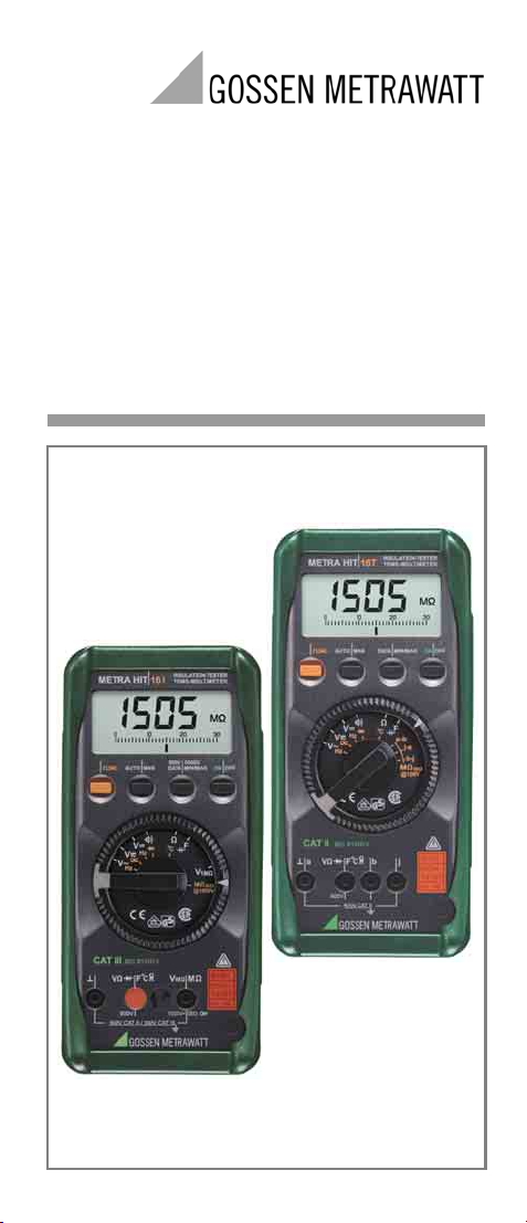
Operating Instructions
METRA HIT⏐16I/L/T
Analog Digital Multimeter
with Insulation Measurement
3-348-892-02
9/5.06
Page 2
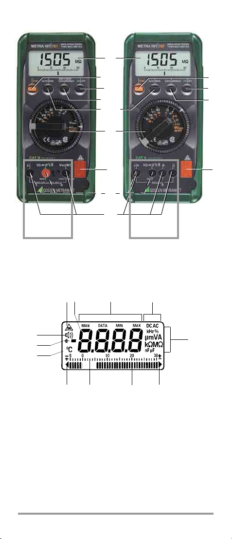
METRA HIT 16I/L METRA HIT 16T
(1)
(5/5a) (5/5b)
(2)
(3/3a)
(4/4a)
(6)
(7)
(7a)
max. 600 V max. 600 V
(2)
(3)
(8)(8)
(10)
(9)
(20)
(19)
(18)
(17)
2 GMC-I Gossen-Metrawatt GmbH
(11) (12)
(16)
(13)
(14)(15)
Page 3

Measuring Instrument Key
(1) LCD → chapter 4
(2) ON|OFF: Key to switch the instrument on and off →
chapter 2
(3) DATA|MIN/MAX: Key for storage of measured values and
MIN/MAX values → chapter 5 + chapter 6
(3a)
500V|1000V
: Key for test voltage selection → chapter
14.1
(4) AUTO| MAN → chapter 3
→
short: Key for manual measuring range selection
→ long: Activation of automatic measuring range
selection
(4a) + (5a) Continuous operation for insulation resistance
measurement →chapter 14.2
(5) FUNC: Multifunction key → chapter 7 ff.
→ short: Activation of measuring sub functions,
e.g. Hz,
, , °C (red symbols)
→ long: Activation of measuring main function
(white symbols)
(5a) Key for performing insulation resistance measurement
(as long as key is held) → chapter 14
(5b) Key for activating and deactivating → chapter 15
of insulation resistance measurement
(6) Rotary switch for measuring functions → chapter 7 ff.
(7)
Connector jacks for multimeter measurement → chapter
(7a) Connector jacks for insulation resistance measurement
→ chapter 14 + chapter 15
(8) DKD calibration mark → chapter 1
GB
3
LCD Key
(9) Symbol for indication of continuous operation
(10) Digital display with decimal point and polarity indication
(11) Display for manual measuring range selection
and storage of measurement and MIN/MAX values
(12) DC/AC display
(13) Unit of measurement display
(14) Overrange display
(15) Analog display pointer
(16) Analog display scale
(17 Display for violation of negative analog display range
(18) Unit of measure display, °C, for temperature
measurement
(Prerequisite: temperature sensor as accessory)
(19) Insufficient battery voltage display
(20) Acoustic warning active display
GMC-I Gossen-Metrawatt GmbH 3
Page 4

Table of Contents
Page
1 Safety Features and Precautions ....................................5
2 Initial Start-Up ................................................................. 7
3 Selection of Measurement Functions
and Measuring Ranges ................................................... 8
3.1 Automatic Range Selection ................................................. 8
3.2 Manual Measuring Range Selection .................................... 8
3.3 Quick Measurements ......................................................... 8
4 LCD Display ..................................................................... 9
4.1 Digital Display ................................................................... 9
4.2 Analog Display .................................................................. 9
5 Measurement Value Storage, “DATA” ............................. 9
6 Minimum and Maximum Value Storage ........................10
7 Voltage Measurement ................................................... 11
7.1 METRA HIT 16I/L: 1 MΩ Input Impedance ........................ 11
7.2 METRA HIT 16T: Terminal Assignments ............................ 11
7.3 Transient Overvoltages ..................................................... 12
7.4 Measurement of Voltages Greater than 600 V ...................12
7.5 Duty Cycle Measurement only with METRA HIT 16L ........... 12
8 Resistance Measurement .............................................. 13
9 Alternating Current Measurement
with the WZ12B Clip-On Current Transformer .............. 13
10 Diode and Continuity Testing ........................................ 14
11 Capacitance Measurement ........................................... 15
12 Frequency Measurement ..............................................15
13 Temperature Measurement .......................................... 16
14 Insulation Resistance Measurement
with the METRA HIT 16I/L ............................................. 17
14.1 Preparation for Measurement ........................................... 17
14.2 Insulation Resistance Measurement .................................. 18
14.3 Conclusion of Measurement and Discharging .................... 18
14.4 Evaluation of Measurement Values ................................... 18
15 Insulation Resistance Measurement at Telecommunicati-
ons Equipment with the METRA HIT 16T ...................... 19
15.1 Evaluation of Measurement Values ................................... 20
16 RS232C Interface .......................................................... 20
17 Characteristic Values ................................................... 21
18 Maintenance ................................................................. 27
18.1 Battery ............................................................................ 27
18.2 Housing .......................................................................... 28
19 Accessories ................................................................... 28
19.1 General ........................................................................... 28
19.2 Characteristic Values of Measuring Cables
(Scope of Supply of Safety Cable Set KS17-2) ...................28
20 Repair and Replacement Parts Service
DKD Calibration Lab and Rental Instrument Service ..... 29
21 Warranty ........................................................................ 29
22 Product Support ............................................................ 29
4 GMC-I Gossen-Metrawatt GmbH
Page 5

1 Safety Features and Precautions
You have selected an instrument which provides you with a high
level of safety.
This instrument fulfills the requirements of the applicable European
and national EC guidelines. We confirm this with the CE marking.
The relevant declaration of conformity can be obtained from GMC-I
Gossen-Metrawatt GmbH.
This analog-digital multimeter has been manufactured and tested in
accordance with safety regulations IEC 61010–1:2001/EN 61 010–
1:2001/VDE 0411–1:2002 und IEC 61557/EN 61 557/VDE 0413.
When used for its intended purpose (see definition below), safety of
the operator, as well as that of the instrument, is assured. Their
safety is however not guaranteed, if the instrument is used improperly or handled carelessly.
In order to maintain flawless technical safety conditions, and to assure safe
use, it is imperative that you read the operating instructions thoroughly and
carefully before placing your instrument into service, and that you follow all
instructions contained therein.
For y our safety, as well as for the protect ion of yo ur instr ument, the
multimeter METRA HIT 16 I/L are equipped with an automatic
socket blocking device. This is coupled to the rotary switch, and
only allows connection to the socket required for the selected function. It also prevents the switching of the rotary selector to disallowed functions when a measurement cable is plugged into a
socket.
Use for Intended Purpose:
– The multimeter described herein is a portable instrument which
can be held in one hand during measurements.
– Only such measurements are performed as described in chap-
ters 7 to 15.
– The measuring instrument including measuring cables and plug-
on test probes is only used within the measuring category indicated under the heading "Electrical Safety" on page 26 (refer to
the table on page 6 for the meaning of the measuring categories).
– The limits of the overload capacity may not be exceeded. Refer
to the Characteristic Values on page 22 and page 23 for the
duration and values of the overload capacity.
– Measurements are only performed within the specified ambient
conditions. Refer to page 27 for the operating temperature range
and relative humidity.
– The measuring instrument is only used in accordance with the
specified protection type, see page 27.
Observe the following safety precautions:
• The instrument may only be operated by persons who are capa-
ble of recognizing contact hazards and taking the appropriate
safety precautions. Contact hazards exist anywhere, where voltages of greater than 33 V may occur (effective value).
• Avoid working alone when taking measurements which involve
contact hazards. Be certain that a second person is present.
• The maximum allowable voltage between any given connector jack
(7) and earth is equal to 600 V cat. II or 300 V cat. I II. Overload
capacities are listed in chapter 17.
•The nominal voltage of the system must not exceed 600 V.
Perform voltage measurements only when switch is set to V ,
V or V .
• Be prepared for the occurrence of unexpected voltages at
devices under test (e.g. defective devices).
For example, capacitors may be dangerously charged.
GB
GMC-I Gossen-Metrawatt GmbH 5
Page 6
• Make certain that the measurement cables are in flawless condi-
tion, e.g. no damage to insulation, no interruptions in cables or
plugs etc.
• Special care is required when measurements are made in HF
electrical circuits. Dangerous pulsating voltages may be present.
• Measurements under moist ambient conditions are not allowed.
• Be absolutely certain that the measuring ranges are not overloaded
beyond their allowable capacities. Limit values can be found in the
table in chapter 17 „Characteristic Values“.
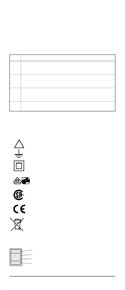
Measuring Categories and their Meaning per IEC 61010-1
CAT Definition
Measurements in electrical circuits
not directly connected to the mains system:
I
e. g. power systems in motor vehicles or aeroplanes, batteries ...
Measurements in electrical circuits
directly connected to the low-voltage system:
II
via plug, e.g. in households, offices, laboratories ...
Measurements in facility installations:
III
stationary consumers, distributor connections, devices attached to a
distributor
Measurements at the source of low-voltage installations:
IV
Meters, main terminal, primary overcurrent protection devices
The measurement category and the relevant maximum rated voltage (e. g. 300 V CAT I II) which are shown on the instrument casing
apply to your measuring instrument.
Meanings of Symbols on the Instrument
Warning concerning a point of danger
!
(Attention: observe documentation)
Earth
Continuous, doubled or reinforced
insulation
VDE testing authority approval mark
CSA approval mark
(North American test authority)
Indicates EC conformity
This device may not be disposed of with the
trash. Further information regarding the
WEEE mark can be accessed on the Internet
at www.gossenmetrawatt.com by entering
the search term ’WEEE’.
DKD calibration mark (red seal):
B0730
DKD-K-
19701
01-07
6 GMC-I Gossen-Metrawatt GmbH
Consecutive number
German calibration service calibration laboratory
GMC-I Gossen-Metrawatt GmbH calibration laboratory
Date of calibration (year – month)
Page 7

Repair, Parts Replacement and Balancing
When the instrument is opened, voltage conducting parts may be
exposed. The instrument must be disconnected from the measuring circuit for repair, replacement of parts or balancing. If repair or
balancing of a live, open instrument is required, this may only be
carried out by trained personnel who are familiar with the dangers
involved.
Errors and Extraordinary Strains
If it may be assumed that the instrument can no longer be operated
safely, it must be removed from service and secured against unintentional use.
Safe operation can no longer be relied upon,
• if the instrument demonstrates visible damage,
• if the instrument no longer functions,
• after a long period of storage under unfavorable conditions.
2 Initial Start-Up
Battery
We have already installed a 9 V flat cell battery in accordance with
IEC 6 LR 61 into your instrument. The instrument is ready for operation. Refer to chapter 18.1 „Battery“, before placing your instrument into
service for the first time, or after it has been in storage.
Switch the Instrument On
➭ Press the ON |OFF key.
Activation is acknowledged with an acoustic signal. As long as
the key remains pressed, all segments of the liquid crystal display
(LCD) are active. The LCD is shown on page 2.
After the key is released, the instrument is ready for operation.
After the instrument has been switched off, it cannot be switched
back on for at least 3 seconds.
Note: Electrical discharge and high frequency interference can
cause incorrect displays, and may block the measuring sequence.
To reset, switch the instrument off, and then back on. If this procedure is unsuccessful, briefly disconnect the battery from the contact terminals.
Before opening the instrument, disconnect it from the measuring circuit
and refer to chapter 18 „Maintenance“!
Automatic Shut-Off
The instrument is switched off automatically if the measurement
value remains constant for a period of approximately 10 minutes
(measurement value fluctuation ≤±2 digits), and if none of the keys
or the rotary switch are activated during this time.
Disabling Automatic Shut-Off
The instrument can also be switched to “CONTINUOUS ON”.
Simultaneously press the ON|OFF key and the multifunction key FUNC
when switching the instrument on. The “CONTINUOUS ON” function is indicated at the LCD with the (8) symbol.
Switching the Instrument Off
Press the ON| OFF key.
GB
GMC-I Gossen-Metrawatt GmbH 7
Page 8
3 Selection of Measurement Functions
and Measuring Ranges
METRA HIT 16I/L: The socket blocking device only allows for connection to the jacks which are required for the selected function.
3.1 Automatic Range Selection
The multimeter is equipped with automatic measuring range selection for all measuring ranges, except for 30 mV and 300 mV .
This automatic feature is active as soon as the instrument is
switched on. The instrument automatically selects the measuring
range which provides optimum resolution for the measured quantity.
The previously selected voltage measuring range remains active
after switching to the frequency measuring mode.
The instrument is automatically switched to:
– the next highest range at ± (3099 digits + 1 digit)
– the next lowest range at ± (240 / 280 digits – 1 digit)
3.2 Manual Measuring Range Selection
The automatic measuring range feature can be deactivated and the
ranges can be manually selected and locked in according to the following table.
The manual mode is deactivated by pressing and holding key
AUTO| MAN (approx. 1s), by activating the rotary switch or by switching the instrument off, and back on again.
When the instrument is switched back to automatic range selection
in the 30 mV or 300 mV ranges, the 3 V range is activated.
⇓
AUTO/
MAN (4)
Brief
V : 3V→ 30 V → 300 V → 600 V → 30 mV →
300 mV → 3V→ ...
V/:3V→ 30 V → 300 V → 600 V → 3V→ ...
Brief
Ω :30MΩ→ 30 Ω→ 300 Ω→ 3kΩ→ 30 kΩ→
300kΩ→ 3MΩ→ 30 MΩ ...
F : 30 nF1)→ 300 nF → 3 μF → 30 μF1)→ 30 nF1)...
Hz : 300 Hz → 3kHz→ 30 kHz → 100 kHz →300 Hz ...
Long Return to Automatic Range Selection — 2 x
1)
METRA HIT 16I/L only
Function
Manual Mode Active:
selected measuring range is fixed
switching sequence for:
Acknowledge
Display
MAN
(10)
MAN
(10)
Acoust.
Signal
1 x
1 x
3.3 Quick Measurements
If you wish to perform quicker measurements than those possible
with the automatic measuring range selection function, make sure
to establish the appropriate measuring range:
•by manual measuring range selection, i. e. by selecting the measur-
ing range with the best resolution, see chapter 3.2.
or
•via DATA function, see chapter 5. After the first measurement, the
proper measuring range will be automatically determined so that
measurements are performed more rapidly from the second
measured value onwards.
With both functions, the established measuring range is maintained
for the subsequent series mode measurements.
8 GMC-I Gossen-Metrawatt GmbH
Page 9

4LCD Display
4.1 Digital Display
The digital display (9) shows the measurement value with correct
decimal point and sign. The selected unit of measure (12) and the
current type (11) are also displayed. A minus sign appears in front
of the value for zero-frequency quantities, if the positive pole of the
measured quantity is applied to the “⊥” input. “OL” is displayed if an
upper range limit of 3099 is exceeded (within range: 1999).
The digital display is refreshed twice per second for the measurement of V and Ω.
4.2 Analog Display
The analog display with pointer demonstrates the dynamic characteristics of a moving coil mechanism and is refreshed 20 times per
second for V and Ω measurements. The analog display is especially
advantageous for the observation of measurement value fluctuations and for balancing.
The analog display has its own polarity indicator. The negative
range of the analog scale (15) includes 5 graduations for the measurement of zero-frequency quantities, so that fluctuations around
zero can be observed. If the measurement value exceeds the display range the triangle at the left side (16) is first displayed, and
then, after about 0.7 s, polarity at the analog display is reversed.
Overranging (> 3099 digit, or > 1999 in the range) is indicated
with the triangle at the right side (13).
5 Measurement Value Storage, “DATA”
Measurement values can be automatically “frozen” with the DATA
function. This can be especially useful when contacting the measuring point with the test probes requires your full attention. After
the measurement value has been acquired and the appropriate
“condition” has been fulfilled according to the following table, the
measured quantity is frozen at the digital display and an acoustic
signal sounds. The test probes can now be removed from the measuring point and the measurement value can be read from the digital display (9). If the measurement value lies below the limit value
shown in the table, the instrument is reactivated for the storage of a
new value.
The DATA function has no effect on the analog display, from which
you can continue to read the current measurement value. However,
when the digital display has been frozen, the decimal point can no
longer be shifted. Thus if automatic measuring range selection has
been activated, you are no longer able to determine which measuring range is active for the analog display. Manual measuring range
selection is disabled, as long as the DATA function is active.
Function
DATA
Activate brief blinks 1 x
Store
Reactivate
Cancel long is deleted is deleted 2 x
1)
Reactivation when actual value falls below prescrib ed limit value
2)
Except for 30 mV and 300 mV ranges
⇓
DATA
MIN/MAX
(3)
1)
Condition Reaction at Instrument
Meas. Value
Measuring
Range
V
V
F, H z
F, H z
Limits
(digits)
2)
>280
Ω
<OL
>280
2)
<280
Ω
OL
<280
Value
Digital
is
displayed
stored
meas.
value
Display
DATA
is
displayed
blinks
Acoustic
Signal
1 x
GB
The DATA function is deactivated if you press an hold key
DATA|MIN/MAX (approx. 1 s), if the rotary switch is activated or if the
instrument is switched off and back on again.
GMC-I Gossen-Metrawatt GmbH 9
Page 10

6 Minimum and Maximum Value Storage
Minimum and maximum values which occur at the measuring
instrument input after the MIN/MAX function has been activated
can be “frozen”. The most important application for this function is
the determination of minimum and maximum values for long-term
observation of measured quantities.
MIN/MAX has no effect on the analog display, from which you can
continue to read the current measurement value.
Apply the desired quantity to the instrument and select the measuring range before activating the MIN/MAX function.
If the function has been activated, measuring range selection can
only be accomplished manually. However, this causes the deletion
of currently stored minimum and maximum values.
The MIN/MAX function is deactivated by pressing and holding key
DATA|MIN/MAX (approx. 1 s), by turning the rotary switch or by
switching the instrument off and back on again.
Reaction at Instrument
Display
Value
MIN MAX
digital
current
MIN and
meas.
MAX
value
blink
stored
stored
MAX
value
MIN 1 x
MAX 1 x
1.
MIN value
same as 1.same as
Acous-
tic
Signal
1 x
1 x
Function
MIN/MAX
1.
Activate and
Store
2.
Store and
Display
3.
Return to 1.
Cancel
⇓
DATA
MIN/MAX
(3)
2 x short,
30 mV/
300 mV
and °C :
1 x short
short
short
short
long
Meas.
Range
V
Ω, F, Hz,
°C, °F
V
Ω, F, Hz,
°C, °F
same as
1.
MIN and MAX
Measurement Val-
ues
are stored
storage continues in
background, new
MIN and MAX
values are displayed
same as 1.
stored values are
not deleted
are deleted is deleted is deleted 2 x
10 GMC-I Gossen-Metrawatt GmbH
Page 11

7 Voltage Measurement
➭ Set the rotary switch to V , V or V depending upon the
voltage to be measured.
➭ Connect the measurement cables as shown. The “⊥” jack should
be grounded.
Zero Balancing in the 30 mV Measuring Range
Zero balancing is accomplished in the 30 mV range as follows:
➭ Connect the measurement cables to the instrument, and con-
➭ Briefly press the multifunction key FUNC after the measuring range
The instrument acknowledges zero balancing with an acoustic signal and “
mal point. The voltage which was displayed at the moment the key
was activated serves as a reference value (max. ±200 digits). It is
automatically subtracted from subsequently measured values.
Zero balancing can be deleted:
– by pressing and holding the multifunction key FUNC, after which
– by switching the instrument off.
Note!
The 30 mV and 300 mV meas. ranges can only
be selected manually with the AUTO|MAN key!
In the 600 V range, an intermittent acoustic signal
sounds alarm if the measurement value exceeds the
measuring range upper limit value.
nect the free cable ends to one another.
has been selected.
00.00” (+ 1 digit) appears at the LCD with a blinking deci-
deletion is acknowledged with a twice repeated acoustic signal.
Voltage Measurement
METRA HIT 16I/L METRA HIT 16T
VF
°
C
V1MM
600V
1000V=ISO 600V
– (+)
~
+ (–)
~
VF
a
°
C
bj
– (+)
~
+ (–)
~
7.1 METRA HIT 16 I/L: 1 MΩ Input Impedance
The measuring instrument is equipped with a V
position with an input impedance of approx. 1 MΩ specifically for
electricians. This reduces incorrect measurement results caused by
capacitive coupling during voltage measurement in electrical power
networks to a minimum.
selector switch
1MΩ
7.2 METRA HIT 16 T: Terminal Assignments
Caution!
!
No connections may be made to jacks b and j, in order to
avoid potential transfer from the ⊥ jack.
GMC-I Gossen-Metrawatt GmbH 11
GB
Page 12

7.3 Transient Overvoltages
The METRA HIT 16I/L and T multimeters are protected against
transient overvoltages of up to 6 kV with a rise time of 1.2 and a
decay time of 50 μs. Due to the fact that overvoltages of greater
duration can be expected when performing measurements, for
example in power supply networks or at transformers and motors,
we recommend our KS30 measuring adapter for such cases. It
provides for protection against transient overvoltages of up to 6 kV
with a rise time of 10 and a decay time of 1000 μs. Continuous
loading capability is equal to 1200 V
When using the measuring adapter KS30 the additional measurement is about approx. –2%.
.
eff
7.4 Measurement of Voltages Greater than 600 V
Voltages of greater than 600 V can be measured with a
high-voltage probe, e.g. HV3 or HV30 from GMC-I Gossen-Metrawatt GmbH. The bonding terminal must be grounded for measurements of this type, and all required safety precautions must be
observed!
METRA HIT 16I/L
VF
°
C
600V
1000V=ISO
red
black
V1MM
Measurement of Voltages
greater than 600 V
with the HV3 High-Voltage
Probe
x1000
x100
black
7.5 Duty Cycle Measurement only with METRA HIT 16L
With a duty cycle measurement, you can determine the ratio of
pulse duration to cycle time of regularly recurring square-wave signals.
➭ Set the function selector switch to V/Hz/% or V~/Hz/%.
➭ Connections are made in the same way as for voltage measure-
ment.
➭ Briefly press the yellow multi-function pushbutton twice. The
meter switches to duty cycle measurement. The duty cycle – that
is the percentage pulse duration of a signal – is displayed on the
LCD in %.
Duty cycle (%) = ——————— • 100
Pulse duration
Cycle duration
Notes
The applied frequency must remain constant during the duty cycle
measurement.
Repeated brief pressing of the multifunction key FUNC changes the
measuring functions in the following order: Voltage → frequency →
duty cycle → voltage → ….
12 GMC-I Gossen-Metrawatt GmbH
Page 13

8 Resistance Measurement
➭ Be certain that the device under test is voltage-free. Extraneous
voltages distort the measurement results!
➭ Set the rotary switch to “Ω”.
➭ Connect the DUT as shown.
Zero Balancing in the 30 Ω Measuring Range
Cable and transition resistance can be eliminated with zero balancing for measurements of small resistance values in the in 30 Ω
range:
➭ Connect the measurement cables to the instrument, and con-
nect the free cable ends to one another.
➭ Briefly press the multifunction key FUNC.
The instrument acknowledges zero balancing with an acoustic
signal and “
decimal point. The resistance which was measured at the
moment the key was activated serves as a reference value
(max. 200 digits). It is automatically subtracted from subse-
quently measured values.
Zero balancing can be deleted:
– by pressing and holding the multifunction key FUNC, after which
deletion is acknowledged with a twice repeated acoustic signal.
– by switching the instrument off.
00.00” (+1 digit) appears at the LCD with blinking
Resistance Measurement
METRA HIT 16I/L METRA HIT 16T
VF
°
C
600V
V1MM
1000V=ISO
VF
a
600V
°
C
bj
GB
R
x
Voltage Drop
See chapter 14 and chapter 15 for insulation resistance measurement.
R
x
Voltage Drop
9 Alternating Current Measurement
with the WZ12B Clip-On Current Transformer
The rotary selector can be switched to the position for measurements with a clip-on current transformer. The measurement
value is displayed directly in A when the WZ12B clip-on transformer
is used.
➭ Read the operating instructions for the WZ12B.
➭ Turn the rotary switch to and briefly press the yellow multi-
function key.
➭ Connect the measurement cables to jacks “⊥” and .
Abbreviated Technical Data, WZ12B
Measuring Range 10 mA ... 100 A
Frequency Range 50 ... 500 Hz
Transformation Ratio 1 mV/10 mA
GMC-I Gossen-Metrawatt GmbH 13
Page 14

10 Diode and Continuity Testing
c
c
➭ Be certain that the device under test is voltage-free. Extraneous
voltages distort the measurement results!
➭ Set the rotary switch to .
➭ Connect the DUT as shown.
Conducting Direction and Short-Circuit
The instrument displays forward voltage in volts. As long as the
voltage drop does not exceed the maximum display value of
1.999 V, you can test several elements connected in series, or reference diodes with small reference voltages.
Reverse Direction or Interruption
The measuring instrument indicates overflow “OL”.
Diode and Continuity Testing with Acoustic Signal
If the “acoustic signal” function is activated, the instrument generates a continuous tone for displayed values between 0 and approx.
1.1 V, or for < 1.8 kΩ.
Acoustic Signal ON (default condition)
After the “diode and continuity testing” function has been activated
with the rotary switch, the acoustic signal is always activated. The
brief activation of the multifunction key FUNC switches the acoustic
signal alternately on and off.
Acoustic Signal OFF
➭ Briefly press the multifunction key FUNC.
Note!
Resistors and semiconductor paths connected in parallel to the diode distort measurement results!
symbol (19) is simultaneously displayed at the LCD. Repeated
Deactivation is acknowledged with an acoustic signal. The
symbol (19) disappears from the LCD. By pressing and holding the key, the acoustic signal is always activated, which is
acknowledged with a twice repeated acoustic signal.
Diode Testing
METRA HIT 16I/L METRA HIT 16T
VF
a
°
600V
C
bj
Forward Dire
Reverse Dire
VF
°
C
V1MM
600V
1000V=ISO
Forward Direction
Reverse Direction
14 GMC-I Gossen-Metrawatt GmbH
Page 15

11 Capacitance Measurement
➭ Be certain that the device under test is voltage-free. Extraneous
voltages distort the measurement results!
➭ Set the rotary switch to “F”.
➭ Connect the (discharged!) DUT to the “⊥” and “F” jacks with
measurement cables.
Note!
For polarized capacitors, the “–” pole must be connected to the “⊥” jack.
Resistors and semiconductor paths connected in parallel to the capacitor distort measurement results!
Zero Balancing in the 30 nF Measuring Range
The inherent capacitance of the instrument and the capacitance of
the cables can be eliminated with zero balancing for the measurement of small capacitive values in the 30 nF range:
➭ Connect the measurement cables to the instrument without a
DUT.
➭ Briefly press the multifunction key FUNC.
The instrument acknowledges zero balancing with an acoustic
signal and “
point. The capacitance which was measured at the moment the
key was activated serves as a reference value (max. 200 digits). It
is automatically subtracted from subsequently measured values.
Zero balancing can be deleted:
– by pressing and holding the multifunction key FUNC, after which
deletion is acknowledged with a twice repeated acoustic signal.
– by switching the instrument off.
00.00” (+1 digit) is displayed with blinking decimal
12 Frequency Measurement
Frequency measurement is possible in all voltage measuring ranges
in the AC and DC operating modes.
➭ Set the rotary switch to V or V .
➭ Apply the measured quantity in the same fashion as for voltage
measurement.
Observe footnote 4) on page 22.
➭ Briefly press the multifunction key FUNC.
The instrument switches to frequency measurement, and the frequency is displayed at the LCD.
The lowest measurable frequencies and maximum allowable
voltages can be found in chapter 17 „Characteristic Values“.
Switching between Voltage and Frequency Measurement
Repeated brief activation of the multifunction key FUNC causes continuous alternation in the following sequence:
voltage → frequency → voltage → ....
You can switch from frequency measurement directly back to voltage measurement by:
– pressing and holding the multifunction key FUNC. This is acknowl-
edged by the instrument with a twice repeated acoustic signal.
The voltage measuring range which was last selected remains
active.
– activating the rotary switch.
GB
GMC-I Gossen-Metrawatt GmbH 15
Page 16

13 Temperature Measurement
Temperature can be measured in °C or °F with the help of Pt 100
and Pt 1000 temperature sensors.
➭ Set the rotary switch to “Ω”.
➭ Connect the sensor to the multimeter measurement jacks (7).
➭ Press the multifunction key FUNC once for display in °C, twice for
display in °F, and three times for the compensation of measurement cable resistance.
The instrument switches to temperature measurement and automatically recognizes the sensor type (Pt 100 or Pt 1000).
The measured temperature value is displayed. The temperature
unit of measure is only displayed for °C.
Note!
The cable resistance for GMC-I Gossen-Metrawatt
GmbH accessory temperature sensors is automatically
taken into consideration during this measurement.
Switching to temperature measurement is disabled if
the 30 Ω resistance measurement range has been activated!
Compensation of Sensor Cable Resistance of up to 20 Ω
Cable resistance values which differ from those of GMC-I GossenMetrawatt GmbH sensor cables can be compensated for up to a
value of 20 Ω as follows:
➭ Press the multifunction key FUNC repeatedly, until the current
cable resistance value is displayed.
The resistance value is then displayed at the LCD, which will be
used for automatic compensation after the temperature measuring range has been activated.
➭ Correction resistance can be adjusted as follows:
Press the DATA | MIN/MAX key to increase the value, or the
AUTO| MAN key to reduce the value. The value is changed by one
digit each time the key is pressed. Continuous, rapid changing
occurs if the key is pressed and held.
➭ Briefly press the multifunction key FUNC again.
The measured temperature is displayed at the LCD. The blinking
decimal point indicates that you have entered a correction value
for cable resistance. The correction value remains until the instrument has been switched off.
➭ Each time the multifunction key FUNC is activated, the display
switches from °C, to °F and to the cable resistance correction
value.
The temperature measurement function can be exited by:
– pressing and holding the yellow multifunction key FUNC, which is
acknowledged by a twice repeated acoustic signal,
– by switching the instrument off.
Note!
Use only the multimeter which will also be used for temperature measurement for the determination of cable
resistance. Otherwise you cannot be certain that measurement error is held within the guaranteed range.
16 GMC-I Gossen-Metrawatt GmbH
Page 17

14 Insulation Resistance Measurement
with the METRA HIT 16I/L
14.1 Preparation for Measurement
➭ Set the rotary switch to “V1MΩ”.
➭ Connect the measurement cables to the two jacks which have
This selector switch position provides for the measurement of interference voltage.
➭ Turn the rotary switch to “MΩ
Note!
Insulation resistance may only be measured at voltagefree objects.
When measuring high-ohmic insulation resistances do
not touch the measurement cables.
been released by the automatic blocking system.
test is voltage-free.
ISO @1000V
” when the device under
Note!
Position MΩ
tion resistance measurement. Any inadvertently applied
interference voltage, however, is displayed in this position.
If an interference voltage of > 50 V is present within the
system, insulation resistance measurement is disabled.
The interference voltage is displayed at the LCD. If a
voltage of greater than 1000 V has been applied, this is
indicated additionally with an acoustic
signal.
may only be selected for insula-
ISO @1000V
High-Voltage!
Do not touch the conductive ends of the test probes
after insulation resistance measurement has been activated at the instrument.
A current with a value of 2.5 mA (limited by the instrument) may flow over your body, and although this is not
life endangering, the electric shock is distinctly perceptible.
If you are taking a measurement at a capacitive DUT, for
example a cable, it may be charged with as much as
1000 V, depending upon the selected nominal voltage.
Touching the DUT after measurement may be life
endangering in such cases!
GB
Test Voltage Selection: 500 V or 1000 V
➭ If the 500V |1000V key is briefly activated, the currently selected
test voltage is displayed.
➭ In order to select the other value, press and hold the 500V| 1000V
key until the other value is displayed and acknowledged with an
acoustic signal.
Insulation Resistance Measurement
METRA HIT 16I/L
VF
°
C
V1MM
600V
1000V=ISO
R
ISO
GMC-I Gossen-Metrawatt GmbH 17
Page 18

14.2 Insulation Resistance Measurement
➭ For insulation resistance measurement, press and hold the multi-
function key FUNC until the display has stabilized. Insulation resistance measurement is ended when the key is released.
An insulation resistance of less than 1 MΩ with a test voltage of
500 V, or less than 2 MΩ with a test voltage of 1000 V is indicated
with an acoustic signal.
Automatic measuring range selection is active for insulation resistance measurement. Their is no provision for the manual selection
of the measuring range.
Note!
The instrument’s batteries are rapidly depleted during
insulation resistance measurement. Only press and hold
the mutlifunction key as long as is necessary to take the
reading. Continuous measurement as described below
should only be performed if absolutely necessary.
Use only alkali-manganese batteries in accordance with
IEC 6 LR61.
Continuous Measurement
➭ Activation: Press and hold the multifunction key FUNC and simul-
taneously press the AUTO| MAN key until acknowledgement is indi-
cated with an acoustic signal.
➭ Deactivation: Briefly press the multifunction key FUNC.
14.3 Conclusion of Measurement and Discharging
After the measurement has been completed, any residual voltage is
displayed which may be caused by conductor capacitance.
➭ Discharge the DUT by turning the selector switch to the V
position. Contact with the DUT must be maintained. The reduction in voltage can be observed directly at the LCD.
Do not disconnect the DUT until voltage has dropped to below 25 V!
1MΩ
14.4 Evaluation of Measurement Values
In order to assure that insulation resistance does not violate lower
limit values as prescribed by DIN VDE requirements, the instrument’s intrinsic and influence errors must be taken into consideration.
The minimum values for insulation resistance can be determined
with the following table, which must be displayed under consideration of maximum operating error for the METRA HIT 16I/L (under
nominal conditions of use) in order to assure that the required limit
values are not violated.
Limit Value in MΩ Min. Display in MΩ
0.1 0.11
0.2 0.22
0.5 0.55
1 1.1
2 2.2
5 5.5
10 11
20 22
50 55
100 110
200 220
500 550
1000 1100
2000 2200
18 GMC-I Gossen-Metrawatt GmbH
Page 19

15 Insulation Resistance Measurement
at Telecommunications Equipment
with the METRA HIT 16T
Three jacks, a, b and j, have been provided for measurement at
telecommunications equipment with two conductors and shield.
Insulation testing between a and b, j and a or b and j can be
selected with the function selector switch.
➭ Connect the measuring cables to jacks a, b and j.
VF
a
°
C
bj
600V
Caution!
!
Do not touch the conductive ends of the test probes
after insulation resistance measurement has been activated at the instrument.
If at all possible, only plug in the measurement cable
which is actually required for testing: loose test probes
or cable ends represent a safety hazard. A current with
a value of 1.5 mA (limited by the instrument) may flow
over your body, and although this is not life endangering, the electric shock is distinctly perceptible.
If you are taking a measurement at a capacitive DUT,
for example a cable, it may be charged with as much as
100 V. Touching the DUT after measurement may be
life endangering in such cases!
➭ Turn the selector switch to MΩ
finally to MΩ
age for all three possible conductor pair combinations.
_b-j, in order to display possible interference volt-
ISO
Insulation Resistance
Measurement with METRA Hit 16T
Example:
Measurement of insulation
resistance at a 2 conductor
shielded cable
_a-b, then to MΩ
ISO
_j-a and
ISO
GB
If an interference voltage of > 50 V is present within the system,
insulation resistance measurement is disabled. The interference
voltage is displayed at the LCD. If a voltage of greater than 310 V
has been applied, this is indicated additionally with an acoustic
signal.
➭ To activate insulation resistance measurement: Briefly press the
➭ Turn the selector switch to MΩ
Automatic measuring range selection is active for insulation resistance measurement. Their is no provision for the manual selection
of the measuring range.
GMC-I Gossen-Metrawatt GmbH 19
Note!
Insulation resistance may only be measured at voltagefree objects.
multifunction key FUNC. Insulation resistance for the currently
selected conductor pair is displayed. Insulation resistance values
of less than 1 MΩ are indicated with an acoustic signal.
finally to MΩ
_b-j, in order to perform the desired test.
ISO
_a-b, then to MΩ
ISO
_j-a and
ISO
Page 20

Conclusion of Measurement and Discharging
➭ Briefly press the multifunction key FUNC.
After the measurement has been completed, any residual voltage is
displayed which may be caused by conductor capacitance. The
100 kΩ internal resistance provides for quick discharging. Contact
with the DUT must be maintained. The reduction in voltage can be
observed directly at the LCD. Do not disconnect the DUT until voltage
has dropped to below 25 V!
Note!
The instrument’s batteries are rapidly depleted during
insulation resistance measurement. Deactivate insulation resistance measurement between measurements.
Use only alkali-manganese batteries in accordance with
IEC 6 LR61.
15.1 Evaluation of Measurement Values
In order to assure that insulation resistance does not violate lower
limit values as prescribed by national requirements, the instrument’s
intrinsic and influence errors must be taken into consideration.
The minimum values for insulation resistance can be determined
with the table in chapter 14.4 which must be displayed under consideration of maximum operating error for the METRA HIT 16T
(under nominal conditions of use) in order to assure that the
required limit values are not violated.
16 RS232C Interface
The multimeters are equipped with an serial infrared interface for
the transmission of measurement data to computer systems. The
measurement values are optically transmitted through the housing
to an interface adapter via infrared light, which can be plugged onto
the multimeter. Data are then transmitted to the computer by
means of a RS232 cable.
Activating the Interface
➭ Press the ON |OFF and DATA|MIN/MAX keys simultaneously when
switching the instrument on.
After the interface has been activated, automatic shut-off is disabled for the instrument. This is indicated at the LCD (1) with the
blinking symbol (8).
The “DATA” function cannot be activated.
Accessory Interface Packs
Interface adapters without memory provide for the transmission of
measurement data from up to two multimeters to a PC.
Memory adapters also allow for on-site storage of measurement data
without a PC, and stored data can be subsequently uploaded to a
PC. Up to 10 multimeters can be interconnected off-line for the
establishment of a high performance, multiple measuring system.
On-line connection of up to six multimeters to a PC via memory
adapters is also possible (single-channel memory pack or 4-channel memory pack).
All interface packs include adapters, connector cables and
“METRAwin 10” data logging and analysis software with operating
instructions.
20 GMC-I Gossen-Metrawatt GmbH
Page 21

17 Characteristic Values
Meas.
Meas. Range Resolution Input Impedance
Function
30.00 mV 10 μV >10 GΩ //<40pF
300.0 mV 100 μV >10 GΩ //<40pF
3.000 V 1 mV 11 MΩ //<40pF
V
30.00 V 10 mV 10 MΩ //<40pF
300.0 V 100 mV 10 MΩ //<40pF
600 V 1 V 10 MΩ //<40pF
3.000 V 1 mV 11 MΩ //<40pF
30.00 V 10 mV 10 MΩ //<40pF
1)
V
300.0 V 100 mV 10 MΩ //<40pF
600 V 1 V 10 MΩ //<40pF
3.000 V 1 mV 11 MΩ //<40pF
30.00 V 10 mV 10 MΩ //<40pF
1)
V
300.0 V 100 mV 10 MΩ //<40pF
600 V 1 V 10 MΩ //<40pF
A
30/100 A 10/100 mA —
2)
30.00 Ω 10 mΩ max. 3.2 V
300.0 Ω 100 mΩ max. 3.2 V
3.000 kΩ 1 Ω max. 1.25 V
Ω
30.00 kΩ 10 Ω max. 1.25 V
300.0 kΩ 100 Ω max. 1.25 V
3.000 MΩ 1kΩ max. 1.25 V
30.00 MΩ 10 kΩ max. 1.25 V
2.000 V 1 mV max. 3.2 V
Meas.
Measuring Range Resolution
Function
30.00 nF3)10 pF 250 kΩ 2.5 V
F
Hz
%
°C
°F
1)
True RMS measurement (TRMS)
2)
Measurement with cli-on current meter WZ12B
3)
METRA HIT 16I/L only
4)
METRA HIT 16L only
300.0 nF 100 pF 250 kΩ 2.5 V
3.000 μF1nF 25kΩ 2.5 V
30.00μF3)10 nF 25 kΩ 2.5 V
300.0 Hz 0.1 Hz 1 Hz 45 Hz
3.000 kHz 1 Hz 1 Hz 45 Hz
30.00 kHz 10 Hz 10 Hz 45 Hz
100.0 kHz 100 Hz 100 Hz 100 Hz
4)
2,0 ... 98,0% 0,1 Hz 1 Hz —
– 200.0 ...
+ 200.0 °C
Pt
100
+ 200.0 ...
+ 800.0 °C
– 100.0 ...
+ 200.0 °C
Pt
1000
+ 200.0 ...
+ 800.0 °C
– 300.0 ...
+ 400.0 °C
Pt
100
+ 400.0 ...
+ 999.0 °C
– 145.0 ...
+ 400.0 °C
Pt
1000
+ 400.0 ...
+ 999.0 °C
open-circuit voltage
Discharge
Resis-
f
min
0.1 °C——
0.1 °C——
0.1 °C——
0.1 °C——
0.1 °F——
0.1 °F——
0.1 °F——
0.1 °F——
tance
Vf
min
U
0max
V
GB
GMC-I Gossen-Metrawatt GmbH 21
Page 22

Meas.
Measuring
Function
V
V
V
A
Meas.
Function
%
1)
2)
4), 5)
6)
7)
Range
30.00 mV 0.5 + 3
300.0 mV 0.5 + 3
3.000 V 0.25 + 1
30.00 V 0.25 + 1
300.0 V 0.25 + 1
600 V 0.35 + 1
3.000 V
30.00 V
300.0 V
600 V
3.000 V
30.00 V
300.0 V
600 V
100 A 2.5 + 3 (> 10 digits) 120 A cont.
30.00 Ω 0.5+3
300.0 Ω 0.5+3
3.000 kΩ 0.4+1
Ω
30.00 kΩ 0.4+1
300.0 kΩ 0.4+1
3.000 MΩ 0.6+1
30.00 MΩ 2.0+1
2.000 V 0.25 + 1
Measuring Range
30.00 nF 1.0 + 3
F
Hz
°C
°F
at –20 °C ... +40 °C
Without zero setting: + 35 digits, 3)Without zero setting: +50 digits
Range 3V :4)UE =1,5 V
On the range 3 V , square-wave signal positive on one side 5 ... 15 V or 5 ... 15 V AC,
f = const., not 163.84 Hz or integral multiple.
300.0 nF 1.0 + 3
3.000 μF 1.0+3
30.00 μF 3.0+3
300.0 Hz
3.000 kHz
30.00 kHz 0,5 + 1
100.0 kHz 0,5 + 1
6)
V 2,0... 98,0%
– 200.0 ...
+ 200.0 °C
Pt
100
+ 200.0 ...
+ 800.0 °C
– 100.0 ...
+ 200.0 °C
Pt
1000
+ 200.0 ...
+ 800.0 °C
– 300.0 ...
+ 400.0 °C
Pt
100
+ 400.0 ...
+ 999.0 °C
– 145.0 ...
+ 400.0 °C
Pt
1000
+ 400.0 ...
+ 999.0 °C
30 V :4)UE =15 V
300 V :4)UE =150 V
without probe
Digital Display Intrinsic Error
±(...% of rdg.+... digit)
at reference conditions
2)
1.0 + 3 (> 10 digits)
1.0 + 3 (> 10 digits)
2)
Digital Display Intrinsic Error
±(...% of rdg.+... digit)
at reference conditions
1 Hz ... 1 kHz: ±5 Digit
1 kHz ... 5 kHz: ±5 Digit/kHz
0,5+1
3)
4)
4)
5)
2 Kelvin + 5 digits
7)
1.0+5
2 Kelvin + 5 digits
7)
1.0+5
4 Kelvin + 10 digits
7)
1.0 + 10
4 Kelvin + 10 digits
7)
1.0 + 10
… 100 V
rms
rms
… 300 V
rms
rms
…600 V
rms
rms —
7)
7)
7)
7)
5)
UE = 2,5 V
5)
UE = 25 V
Overload Capacity
Value Duration
600 V
DC
cont.
AC
rms
sine
600 V
DC
max. 10 s
AC
rms
sine
Overload Capacity
Value Duration
600 V
DC / AC
max. 10 s
rms
sine
≤ 600 V
≤ 300 V
cont.
≤ 30 V
see Hz
600 V
DC
max. 10 s
AC
rms
sine
600 V
DC
max. 10 s
AC
rms
sine
… 30 V
rms
rms
… 30 V
rms
rms
22 GMC-I Gossen-Metrawatt GmbH
1)
1)
Page 23

Insulation Measurement, METRA HIT 16I/L / METRA HIT 16 T
Measurement
Function
Switch Setting
MΩ
@1000V
MΩ
@1000V
(UN = 500 V)
METRA HIT 16I/L
MΩ
@1000V
(UN = 1000 V)
MΩ
MΩ
@100V
(UN = 100 V)
METRA HIT 16T
V
1MΩ
Measuring Range Resolution
0 ... 1000 V 1 V ±(1 % of rdg. + 10 d)
ISO
0 ... 1000 V 1 V ±(1 % of rdg. + 10 d)
0.100 ... 1.600 MΩ
ISO
01.40 ... 16.00 MΩ
014.0 ... 160.0 MΩ
0140 ... 1600 MΩ
0.100 ... 3.100 MΩ
ISO
02.80 ... 31.00 MΩ
028.0 ... 310.0 MΩ
0280 ... 3100 MΩ
0 ... 100 V 0.1 V ±(3% of rdg. + 10 d)
ISO
005.0 ... 310.0 kΩ 0.1 kΩ±(3 % of rdg. + 10 d)
ISO
0.280 ... 3.100 MΩ
02.80 ... 31.00 MΩ
028.0 ... 310.0 MΩ
1 kΩ
10 kΩ
100 kΩ
1 MΩ
1 kΩ
10 kΩ
100 kΩ
1 MΩ
1 kΩ
10 kΩ
100 kΩ
Digital Display
Intrinsic Error at
reference conditions
±(3% of rdg. + 2 d)
±(3% of rdg. + 2 d)
±(3% of rdg. + 2 d)
Meas. Func-
16I/L
16T
Meas. Func-
16I/L
16T
16I/L
16T
tion Switch
Setting
V
1MΩ
MΩ
ISO
@1000V
MΩ
ISO
@100V
tion Switch
Setting
V
1MΩ
MΩ
ISO
@1000V
MΩ
ISO
@100V
Measuring
Function
MΩ
ISO
@1000V
MΩ
ISO
@100V
Nominal
Voltage U
1000 V < 1.15 x UN> 1.0 mA < 2.5 mA
Nominal
Voltage U
1000 V Rx<2MΩ 600 V
500 V 100 kΩ ... 1600 MΩ
1000 V 100 kΩ ... 3100 MΩ
100 V 100 kΩ ... 310 MΩ± 10%
Open-Circuit
Voltage U
N
— — — —
— — — —
500 V < 1.15 x UN> 1.0 mA < 2.5 mA
— — — —
100 V < 1.15 x UN> 1.0 mA < 1.5 mA
Acoustic
Signal at:
N
— U > 1000 V 600 V continuous
— U>50V 600V
— U>50V 600V continuous
100 V Rx<1MΩ 600 V max. 10 s
U
Nominal Range of Use
N
Nominal
Current I
o
Value Duration
Short-Circuit
Current Ik
N
Overload Capacity
max. 10 s500 V Rx<1MΩ 600 V
Operating
Meas. Deviation
± 10%
GB
GMC-I Gossen-Metrawatt GmbH 23
Page 24

Influencing Quantities and Influence Errors
Influenc-
Quantity
Tempera-
ing
ture
Sphere of Influ-
ence
0 °C ...
+21 °C
and
+25 °C ... +40 °C
15 Hz ... < 30 Hz
Measured
Frequency
30Hz...<45Hz 0.5+3
Quantity
>65Hz...400Hz 2.0+3
> 400 Hz ... 1 kHz 3.0 + 3
crest
factor CF
> 3 ... 5 ±3 % of rdg.
The allowable crest factor CF dof the periodic quantity to be measured is dependent upon the displayed value:
Measured
Quantity/
Measuring Range
30/300 mV 1.0 + 3
3 ... 300 V 0.15 + 1
600 V 0.2 + 1
V 0.4+2
2)
30 Ω
300 Ω 0.25 + 2
3kΩ ... 3 MΩ 0.15 + 1
30 MΩ 1.0+1
30 nF2) ... 3 μF 0.5+2
30 μF 2.0+2
Hz 0.5 + 1
% ±5 Digit
– 200 ... + 200 °C 0.5 K + 2
+ 200 ... + 800 °C 0.5 + 2
– 300 ... + 400 °F 1.0 K + 4
+ 400 ... + 999 °F 0.5 + 2
16I: MΩ
ISO
16T: MΩ 0.25 + 2
3 ... 600 V
1 ... 3
4)
V
Influence Error 1)
±(... % of rdg. + ... digit)
0.15 + 2
5)
0.25 + 2
1.0+3
±1 % of rdg.
CF
Measured
5
Quantity
Waveform
3)
4
Voltage Measurement
3
2
1
0
0
1000 2000
1)
For temperature:
Indicated error values valid per 10 K change in temperature.
For frequency: Indicated error values valid as of 300 digit display.
2)
With zero setting
3)
If waveform is unknown (crest factor CF > 2) measure
with manual range selection.
4)
Except for sinusoidal waveform
5)
METRA HIT 16T: 2+2
3000
digits
24 GMC-I Gossen-Metrawatt GmbH
Page 25

Influencing
Sphere of Influence
Quantity
Battery
Voltage
Relative
Humidity
DATA — ±1 digit
MIN / MAX — V ±2 digits
1)
as of display of symbol.
1)
> 8.1 V ... 10.0 V
75%
3 days
device off
... < 7.9 V
Measured Quantity/
Measuring Range
V ±2 digits
V ±4 digits
30 Ω/300 Ω/°C/°F ±4 digits
3kΩ ... 30 MΩ±3 digits
MΩ
, MΩ±2 digits
ISO
nF, μF ±1 digit
Hz ±1 digit
% ±1 Digit
V
Ω
MΩ
, MΩ
ISO
Hz
%
°C, °F
Influence Error
1x intrinsic error
Influencing
Quantity
Common-Mode
Interference
Voltage
Series-Mode
Interference
Voltage
Sphere of Influence
interference max. 600 V V > 120 dB
interference max. 600 V
50 Hz, 60 Hz sine
interference V ,
respective nom. value of meas. range,
max. 600 V , 50 Hz, 60 Hz
sine
interference max. 600 V V > 110 dB
Response Time (after manual range selection)
Measured Qty. /
Measuring Range
V , V 0.7 s 1.5 s
30 Ω ... 3 MΩ 1.5 s 2 s
30 MΩ 4s 5s
nF, μF, °C, °F max. 1... 3 s
300 Hz, 3 kHz max. 2 s
30 kHz max. 0.7 s
% (1 Hz) max. 9 s
% (≥ 10 Hz) max. 2,5 s
Response Time
Analog Display D igital Display
0.7 s 1.5 s
Reference Conditions
Ambient
Te mp er a tu r e + 2 3 °C ±2K
Relative Humidity 40 % ... 60 %
Measured Quantity
Frequency 45 Hz ... 65 Hz
Measured Quantity
Wavefor m sine
Battery Voltage 8 V ±0.1 V
Measuring
Range
3 V , 30 V >80dB
300 V >70dB
600 V
V > 50 dB
Measured Quantity Jump
measuring range upper limit
measuring range upper limit
measuring range upper limit
Damping
1)
>60dB
Function
from 0 to 80 % of the
from ∞ to 50 % of the
from 0 to 50 % of the
GB
GMC-I Gossen-Metrawatt GmbH 25
Page 26

Display
LCD (65 mm x 30 mm) with analog and digital display including display of unit of measure, voltage type and various special functions.
Analog
Display LCD scale with pointer
Scale Length 55 mm for V ;
47 mm for all other ranges
Scaling 5 ... 0 ... ±30 with 35 graduations for ,
0 ... 30 with 30 graduations in all other
ranges
Polarity Display with automatic reversal
Overflow Display indicated with triangle (13)
Measurement Rate 20 measurements per second,
for Ω: 10 measurements per second
Digital
Display/Char. Height 7 segment characters / 15 mm
Places 3¾ places 3100 steps
Overflow Display “OL” is displayed
Polarity Display “–” sign is displayed for plus pole to “⊥”
Measurement Rate 2 measurements per second,
for Ω and °C: 1 measurement per second
Power Supply
Battery 9 V flat cell battery,
Measuring
METRA HIT
16I/L, 16T
1)
Times 0.7 with active interface
2)
Nominal
Function
Voltage
V 750
V 150
100 V 1 MΩ 50
MΩ
100 V 100 kΩ 3000
MΩ
Battery test: automatic display of symbol
when battery voltage falls below approx. 7 V
500 V 500 kΩ 600
ISO
1000 V 1 MΩ 200
alkali-manganese cell per IEC 6 LR 61
U
N
Resistance at
DUT
Service Life
in Hours
1)
1)
Number of Possible
Measurements with
Nominal Current per
VDE 0413
2)
Electrical Safety
Protection Class I I per EN 61010-1:2001/VDE 0411-1:2002
Measuring Category II III
Nominal Voltage 600 V 300 V
Pollution Degree 2 2
Test Voltage 3.5 kV~ per EN 61010-1:2001
EMC
Product standard EN 61 326-1: 1997
Interference Emission EN 55022: 1998 – Klasse B
Interference Immunity EN 61 000-4-2: 1995
26 GMC-I Gossen-Metrawatt GmbH
/VDE 0411-1:2002
Electromagnetic Compatibility
EN 61326: 1997/A1: 1998
– 4kV/8kV
contact and atmospheric discharge
– power feature A
EN 61000-4-3: 1996+A1: 1998
– 3 V/m
– power feature B
Page 27

Interface
Type RS232C, serial, per DIN 19241
Data Transmission optical with infrared light through housing
Baud Rate 8192 bit/s
Ambient Conditions
Operating Temp. −20 °C ... + 50 °C
Storage Temp. −25 °C ... + 70 °C (without battery)
Relative Humidity ≤ 75%, no condensation allowed
Elevation to 2000 m
Deployment indoors,
outdoors: only in the specified ambient
conditions
Mechanical Design
dimensions 84 mm x 195 mm x 35 mm
weight approx. 0.35 kg with battery
Protection IP 50
IP XY
st
(1
digit X)
0 not protected 0 not protected
1 ≥ 50.0 mm
2 ≥ 12.5 mm
3 ≥ 2.5 mm
4 ≥ 1.0 mm
5 dust protected 5 water jets
Extract from table on the meaning of IP codes
Protection against
foreign object entry
∅
∅
∅
∅
IP XY
(2nd digit Y)
1 vertically falling drops
2
3 spraying water
4 splashing water
Protection against the
penetration of water
vertically falling drops
with enclosure tilted 15°
18 Maintenance
Caution!
!
The instrument must be disconnected the from the measuring
circuit before opening to replace the battery!
18.1 Battery
Before initial start-up, or after your instrument has been in storage,
make sure that no battery leakage has occurred, and inspect for
battery leakage on a regular basis.
If battery leakage has occurred, the electrolyte must be completely
removed with a damp cloth and a new battery must be installed,
before the instrument is placed back into service.
If the symbol (18) is displayed at the LCD, the battery should be
replaced as soon as possible. You can continue to take measurements, but the accuracy of the instrument may be negatively influenced.
The instrument is powered by a 9 V flat cell battery in accordance
with IEC 6 LR 61. Use only alkali-manganese cells which comply
with IEC 6 LR61.
Replacing the Battery
➭ Lay the instrument onto its face, loosen the two screws at the
rear panel and lift out the housing base, starting at the bottom (a).
The housing base and housing top are held together with snap
hooks at the top of the front panel.
➭ Remove the battery from the battery compartment and carefully
pull the battery from the terminal contacts.
➭ Snap the terminal contacts onto a new 9 V battery and insert the
battery into the battery compartment.
➭
Important for reassembly: First lay the housing base into place as
shown in the diagram below. Push the housing base and housing
top together, first at the bottom front (a) and then at the top front (b).
GB
GMC-I Gossen-Metrawatt GmbH 27
Page 28

(b) (a)
➭ Retighten the housing base with the two screws.
➭ Please dispose of used batteries properly!
18.2 Housing
No special maintenance is required for the housing. Keep outside
surfaces clean. Use a slightly dampened cloth for cleaning. Avoid
the use of cleansers, abrasives or solvents.
Collection of Used Instruments and Environmentally Compatible Disposal
The milliohmmeter is a category 9 product (monitoring and control
instrument) in accordance with ElektroG (German Electrical and
Electronic Device Law). This device is not subject to the RoHS
Directive.
We identify our electrical and electronic devices (as of
August 2005) in accordance with WEEE 2002/96/EG and
ElektroG with the symbol shown to the right per DIN EN
50419. These devices may not be disposed with the
trash. Please contact our service department regarding the return
of old devices (see chapter 20).
19 Accessories
19.1 General
The wide range of accessories available for our multimeters is regularly checked for compliance with the currently valid safety standards and is extended to include new ranges of application, if
required. If you are looking for the appropriate up-to-date accessories including photo, reference number, description as well as,
depending on the scope and complexity of the accessories,
datasheet and operating instructions, please refer to our website
www.gossenmetrawatt.de (→ Measuring Technology – Portable →
Digital Multimeters → METRAHit ... → Accessories).
19.2 Characteristic Values of Measuring Cables (Scope of Supply of Safety Cable Set KS17-2)
Electrical Safety
Maximum Rated Voltage
Measuring Category 1000 V CAT I I I, 600 V CAT IV
Maximum Rated Current 16 A
Ambient Conditions (EN 61010-031)
Temperature –20 °C ... + 50 °C
Relative Humidity 50 ... 80 %
Pollution Degree
2
28 GMC-I Gossen-Metrawatt GmbH
Page 29

20 Repair and Replacement Parts Service
DKD Calibration Lab* and Rental Instrument Service
If required, please contact:
GMC-I Gossen-Metrawatt GmbH
Service-Center
Thomas-Mann-Strasse 20
90471 Nürnberg • Germany
Phone +49-(0)-911-8602-0
Fax +49-(0)-911-8602-253
E-Mail service@gossenmetrawatt.com
This address is only valid in Germany. Please contact our representatives or subsidiaries for service in other countries.
* Calibration Laboratory
for Electrical Quantities DKD– K – 19701
accredited per DIN EN ISO/IEC 17025
Accredited measured quantities: direct voltage, direct current
values, DC resistance, alternating voltage, alternating current
values, AC active power, AC apparent power, DC power,
capacitance and frequency
DKD Calibration Certificate Reprints
If you need to order a reprint of the DKD calibration certificate for
your instrument, please include the ID number shown in the uppermost and lowermost fields of the calibration certificate. We do not
need the instrument’s serial number.
21 Warranty
The warranty period for all measuring and calibration instruments of
the METRA HIT series is 3 years from delivery.
The warranty period for calibration is 12 months. Warranty covers
faulty workmanship and material, not including any damage caused
by improper use and any follow-up costs.
22 Product Support
If required, please contact:
GMC-I Gossen-Metrawatt GmbH
Product Support Hotline
Phone +49-(0)-911-8602-112
Fax +49-(0)-911-8602-709
E-Mail support@gossenmetrawatt.com
GB
GMC-I Gossen-Metrawatt GmbH 29
Page 30

Edited in Germany • Subject to change without notice
• A pdf version is available on the internet
GMC-I Gossen-Metrawatt GmbH
Thomas-Mann-Str. 16-20
90471 Nürnberg • Germany
Phone+49-(0)-911-8602-0
Fax +49-(0)-911-8602-669
E-Mail info@gossenmetrawatt.com
www.gossenmetrawatt.com
 Loading...