

Gossen Metrawatt METRAFLEX 3000, METRAFLEX 3001, METRAFLEX 3001XL, METRAFLEX 3003, METRAFLEX 3003XL User guide
Page 1
______________________________________________________________
3-349-530-37
2/1
2.09
Operating Instructions
METRAFLEX 3000
METRAFLEX 3001 / 3001XL
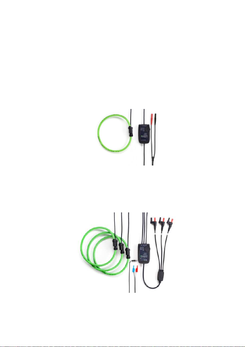
METRAFLEX 3003 / 3003XL (3-Phase Set)
Flexible AC Current Probe
_______________________________________________________________
17
Page 2
_______________________________________________________________
Order Reference Order No.
METRAFLEX 3000 Flexible AC Current Probe 30/300/3000A ............ Z207E
61 cm (24”), battery supply,
3V output on 4mm safety plugs
METRAFLEX 3001 Flexible AC Current Probe 30/300/3000A ............ Z207F
61 cm (24”), battery/external supply,
3V output on 4mm safety plugs;
incl. supply cable for MAVOWATT|50
METRAFLEX 3001XL Flexible AC Current Probe 30/300/3000A ............Z207H
61 cm (24”), battery/external supply,
1.5V output on Hypertronics plug
METRAFLEX 3003 Flexible AC Current Probe 30/300/3000A ............Z207G
61 cm (24”), battery/external supply,
3V output on 4mm safety plugs;
incl. supply cable for MAVOWATT|50
METRAFLEX 3003XL Flexible AC Current Probe 30/300/3000A ..............Z207I
61 cm (24”), battery/external supply,
1.5V output on Hypertronics plug
Other head lengths available on request.
_______________________________________________________________
Page 3

______________________________________________________________
For safety reasons and optimum use of this instrument
read through the operating instructions very carefully.
Thank you for buying this product.
Table of Contents
1. SAFETY ........................................................................................20
2. INTRODUCTION...........................................................................22
3. SPECIFICATIONS ........................................................................23
4. OPERATION................................................................................. 26
4.1 BATTERY INSTALLATION AND BATTERY STATUS..................26
4.2 EXTERNAL POWER SUPPLY .....................................................27
4.3 CONNECTING TO MEASURING DEVICE...................................28
4.4 CONNECTING TO THE CIRCUIT TO BE MEASURED...............29
4.5 MEASUREMENT..........................................................................30
5. MAINTENANCE............................................................................31
6. WARRANTY..................................................................................31
7. PRODUCT SUPPORT ..................................................................32
8. REPAIR AND REPLACEMENT PARTS SERVICE DKD CALIBRATION
CENTRE AND RENTAL INSTRUMENT SERVICE ...................... 32
_______________________________________________________________
19
Page 4
_______________________________________________________________
1. SAFETY
The following symbols appear on the products:
Attention! Refer to Manual
Double/Reinforced Insulation
Do not apply around or remove from HAZARDOUS LIVE
conductors without additional protective means.
“Additional protective means” can be:
- de-energizing the circuit
- wearing protective clothing suitable for high voltage work.
Do not dispose of this product as unsorted municipal
waste. Contact a qualified recycler for disposal.
Indicates EC conformity
_______________________________________________________________
Page 5

______________________________________________________________
The flexible current transformer is manufactured and tested in accordance with
safety regulations IEC/EN 61010-1 / -031 /-2-032. If used for its intended
purpose, safety is assured for the user, the device and the DUT.
Read the operating instructions carefully and thoroughly before placing
the device into operation. Observe and follow all points included therein.
Make the operating instructions accessible to all users.
In particular, observe the following safety instructions.
• Always inspect the electronics unit, connecting cable, and flexible
probe for damage before using this product. Do not use product if
damaged.
• This product must be used only by qualified personnel practising
applicable safety precautions.
• Never apply the probe around bare conductors with hazardous
voltages without having the appropriate permission to perform
such work and without wearing protective clothing and gloves as
required.
• Never apply the probe around bare conductors with voltage levels
over 1000V to ground.
• Always connect electronics unit to measuring device before
installing the flexible measuring head.
• Never change batteries while measurement head is installed on
conductor.
• Never connect or disconnect the external power supply while the
measurement head is installed on a conductor.
• Never connect the output to any equipment with a common mode
voltage to earth greater than 30 Volts.
• If the probe is used in a manner not specified by the
manufacturer the protection provided by the equipment may be
impaired.
_______________________________________________________________
21
Page 6
_______________________________________________________________
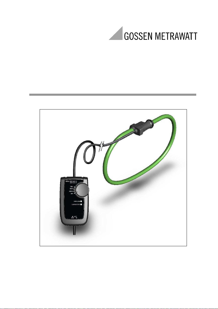
2. INTRODUCTION
The METRAFLEX are AC current probes utilising Rogowski
principle. They can be used to measure AC current up to 3000A
by being connected to an appropriate measuring device
(multimeter, data logger, power analyser etc.). The flexible probe
allows current measurements on conductors that are hard to
reach.
The probes provide an AC output voltage of 0…3V (METRAFLEX
3000/3001/3003) or 0…1.5V (METRAFLEX 3001XL/3003XL),
proportional to the current being measured with three selectable
ranges.
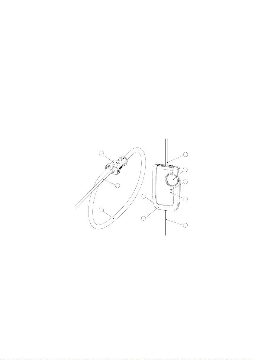
1
2
7
3
8
2
4
5
6
9
1. Probe Coupling
2. Probe Output Cable
3. Flexible Current Probe
4. Power On / Range Switch
5. RED LED – Overload
6. ORANGE LED – Low Battery
7. External Power Supply Input
8. Integrator Housing
9. Output Cable
_______________________________________________________________
Fig 1
Page 7

______________________________________________________________
.
3. SPECIFICATIONS
METRAFLEX 3000
METRAFLEX 3001
METRAFLEX 3003
METRAFLEX 3001XL
METRAFLEX 3003XL
Measuring ranges 30A 300A 3000A 30A 300A 3000A
Scaling factor 10 100 1000 20 200 2000
Output sensitivity 100mV/A
Accuracy (45-65Hz) ±1% of rdg.
Noise 8 mVrms
10mV/A 1mV/A 50mV/A 5mV/A 0,5mV/A
±0,1A
±1% of rdg
±1A
2 mVrms 8 mVrms
±1% of rdg.
±0,1A
2 mVrms
±1% of rdg.
±1A
Output Connector 1 pair 4mm safety plugs 4 pin Hypertronics plug
Power Supply
Battery
Battery Life (typ.)
external*
Connector*
2x AA MN1500 LR6 Alkaline
2000 hrs (M’FLEX 3000/3001)
1000 hrs (M’FLEX 3003)
)
3,5…12VDC/max. 100mA 2…3VDC/max. 100mA
)
Barrel plug socket 5,5/2,1mm
minus at center pin
*) not available for METRAFLEX 3000
2x AA MN1500 LR6 Alkaline
2000 hrs (M’FLEX 3001XL)
1000 hrs (M’FLEX 3003XL)
Barrel plug socket 5,5/2,1mm
minus at center pin
Output load ≥100 kΩ for specified accuracy
Frequency range 10 Hz to 20 kHz (-10% attenuation)
Phase angle error <±1° (45-65Hz)
Position sensitivity ±2% of reading
External field ±0.2% of range with cable >200mm
(8") from the probe
Temperature coeff. ±0.1% / °K
Low battery Indicated by an orange LED
Overload Indicated by a red LED
_______________________________________________________________
23
Page 8

_______________________________________________________________
Enclosure
Material ARNITE T06-200 SNF, UL94 V0
Degree of Protection IP40
Dimensions 110 (l) x 65 (w) x 23 (d) mm
Output connection 0.5m coax cable terminated with 4 mm safety plugs
Probe
Probe length 61 cm (24 inches), double insulated
on request: 91 cm (36 inches),122 cm (48 inches)
Probe diameter 9.9mm (0.39 inches)
Output cable 2m long (78.7 inches), probe to integrator
Material Alcryn 2070 NC, LATI LATENE 7H2W V0
Degree of Protection IP65
General Characteristics
Operating temp. -20°C to +65°C (-4°F to +149°F)
Storage temp. -40°C to +75°C (-40 °F to +167°F)
Operating humidity 15% to 85% (non-condensing)
Safety standards
EN 61010-1:2001
EN 61010-031:2002
EN 61010-2-032:2002
EMC standards
Emmision EN 61326-2:2006 Class B
Immunity EN 61326-2:2006
1000 V
, Category III, 600 V
RMS
, Category IV, Pollution Degree 2
RMS
(Probe and Integrator)
30V maximum between output and earth
ROHS and WEEE compliant
Rated for continuous use
_______________________________________________________________
Page 9

______________________________________________________________
METRAFLEX Frequency Response
2,00
0,00
10
-2,00
100
1000
10000
100000
Relative op % ref 50Hz
Phase error degrees
-4,00
-6,00
-8,00
-10,00
20
15
10
-5
30A range
300A range
Frequency Hz
METRAFLEX Phase Response
100000
30A range
300A range
5
0
10
100
1000
10000
-10
Frequency Hz
_______________________________________________________________
25
Page 10

_______________________________________________________________
4. OPERATION
4.1 BATTERY INSTALLATION AND BATTERY
STATUS
Never replace batteries with flexible measuring head
installed on conductor to be tested or output connected to a
measuring device.
Never operate the unit without the battery cover fitted.
The METRAFLEX require two AA MN1500 LR6 alkaline batteries
for operation. The battery compartment is accessed from the rear
of the electronics enclosure.
Battery status is indicated by an orange LED on the front of the
integrator module. This LED will flash one time when the unit is
switched ON. The length of time the LED is lit will increase as
battery life decreases. Continuous lighting of LED indicates low
battery and requires batteries to be replaced.
Should you suspect a depleted battery or the low battery LED
blinking, proceed as follows.
1. Turn “OFF” all power to the unit and measurement circuits.
2. Set the probe selector switch to the “OFF” position.
3. Remove the flexible current probe from around the conductor
of your measurement circuit. Disconnect the output from the
measuring unit. Remove the external power supply cable.
4. Rotate the battery lock screw (1/4 turn) until it aligns with the
unlock symbol. The battery cover can now be removed.
5. Install the replacement batteries into the battery holder.
Observe correct polarity.
6. Replace the battery cover and turn the battery lock until it
aligns with the lock symbol.
_______________________________________________________________
Page 11

______________________________________________________________
4.2 EXTERNAL POWER SUPPLY
Alternatively, the METRAFLEX can also be supplied by an
external DC voltage source (except METRAFLEX 3000). The
connection is made at the connector on the side of the electronics
housing. Supply voltage range, see Technical Data.
Polarity:
(+ terminal)
For safety reasons and to ensure the specified accuracy, the
current sensors should be supplied exclusively by using the
external power supply modules offered from us as an option.
Our Power Analysers MAVOWATT|50 und MAVOSYS 10 have a
power supply output for active current sensors.
MAVOWATT|50: Up to 4 pcs. METRAFLEX 3001 or 1 pc.
METRAFLEX 3003 and 1 pc. METRAFLEX 3001 can be supplied
by the 9V output named „Aux Supply“. The required connection
cable is supplied with these current sensors. Take care when
connecting the plugs to the Aux. Supply jacks on the correct
polarity (color coding)!
MAVOSYS 10: Up to 3 pcs. METRAFLEX 3003XL and 3 pcs.
METRAFLEX 3001XL can be supplied by the 3V output on the
10 pin socket being located on the rear panel over the mains
switch. The required connection cables are available as
accessories: DC3VFLEX (117067-G1) for up to 4 pcs.
METRAFLEX; RR/PS/4A for expanding to another 3 pcs.
METRAFLEX.
(- terminal)
_______________________________________________________________
27
Page 12

_______________________________________________________________
Read safety section of instructions before operating
4.3 CONNECTING TO MEASURING DEVICE
this product.
METRAFLEX 3000: Plug the output cable of the current sensor
into the voltage measuring input terminals of the multimeter
(black to GND, red to V) and switch it to V AC.
METRAFLEX 3001/3003: Plug each output cable of the current
sensor to the current measuring input terminals “I” on the
MAVOWATT|50. Observe the polarity (color) and with
METRAFLEX 3003 also the phase labeling L1, L2, L3.
METRAFLEX 3001XL/3003XL: Plug each output cable of the
current sensor to the current measuring input terminals on the
MAVOWATT 20/30/40/70 or MAVOSYS 10. With METRAFLEX
3003XL observe the phase labeling.
_______________________________________________________________
Page 13

______________________________________________________________
It is strongly recommended to de
-
energize the c
ircuits to
4.4 CONNECTING TO THE CIRCUIT TO BE
MEASURED
be measured when making connections to the
installation. If it is necessary to make connections on
energized circuits they must be made by qualified and
authorized personnel only observing the required safety
precautions..
Never apply the probe around bare conductors with
voltage levels over 1000V (CAT III) or 600V (CAT IV) to
ground.
Always connect electronics unit to measuring device
before installing the flexible measuring head.
Open the probe coupling and slip the measuring head over the
conductor carrying the current to be measured.
Close the probe coupling such that it visibly and audibly snaps
into place.
An accurate measurement is assured under the following
conditions:
– The conductor is centered within the measuring head.
– The measuring head forms a perfect circle.
– The probe coupling is not located close to other conductors
carrying high current.
_______________________________________________________________
29
Page 14

_______________________________________________________________
4.5 MEASUREMENT
To activate unit, move the rotary switch from the “off” position to
the required measuring range. If the value of current being
measured is unknown, first select the highest range and then
reduce accordingly.
The red and the orange LED might flash when the unit is
switched on or when the measuring range is changed.
To obtain correct results set the scaling factor on the meter or
analyser for each measurement channel corresponding to the
selected measuring range; see table under SPECIFICATIONS.
When measuring active power you also must observe the
direction of the current flowing through the measuring head.
Check the correct polarity at the power analyzers based on the
vector representation of voltage and current, or by the polarity of
the values for active power. These have to be positive for
consumer measurements.
_______________________________________________________________
Page 15

______________________________________________________________
5. MAINTENANCE
Do not use METRAFLEX if damaged.
Always inspect the integrator unit, connecting cable, and flexible
probes for damage before use.
To avoid electric shock, keep the METRAFLEX clean and free of
surface contamination.
Use Isopropyl alcohol to clean the electronics unit and the probe.
Make sure the flexible probe, connecting cable, and electronics
enclosure are dry before further use.
6. WARRANTY
Your METRAFLEX is guaranteed for two years from the date of
purchase against defective material or workmanship. If the unit fails
during the warranty period, we shall at our discretion, repair or
replace it with a new or reconditioned unit provided we are satisfied
that the failure is due to defective material or workmanship. To make
a claim under warranty, the probe should be returned to us, postage
prepaid, with a description of the defect. The use of a battery or
external power supply, other than that specified invalidates this
warranty.
Goods alleged by the buyer to be defective shall not form the subject
of any claim for injury, loss, damage, or any expense howsoever
incurred whether arising directly or indirectly from such alleged
defects other than death or personal injury resulting from the seller‘s
negligence.
No condition is made or to be implied nor is any warranty given or to
be implied as to the life or wear of goods supplied or that they will be
suitable for any particular purpose or for use under specific
conditions, notwithstanding that such purpose or conditions may be
made known to the seller.
_______________________________________________________________
31
Page 16

_______________________________________________________________
7. PRODUCT SUPPORT
If required please contact:
GMC-I Messtechnik GmbH
Product Support Hotline
Phone: +49 911 86 02-0
Fax: +49 911 86 02-7 09
E-mail: support@gossenmetrawatt.com
8. REPAIR AND REPLACEMENT PARTS
SERVICE DKD CALIBRATION CENTRE AND
RENTAL INSTRUMENT SERVICE
If required please contact:
GMC-I Service GmbH
Service Center
Thomas-Mann-Strasse 20
90471 Nürnberg, Germany
Phone: +49 911 817718-0
Fax: +49 911 817718-2 53
E-mail: service@gossenmetrawatt.com
This address is only valid in Germany. Please contact our
representatives or subsidiaries for service in other countries.
_______________________________________________________________
Page 17

______________________________________________________________
GMC-I Messtechnik GmbH
Südwestpark 15
D-90449 Nürnberg
DEUTSCHLAND
Tel. +49 (0)911 8602-111
Fax +49 (0)911 8602-777
e-mail: info@gossenmetrawatt.com
www.gossenmetrawatt.com
METRAFLEX MM Rev 3
_______________________________________________________________
33
 Loading...