

Page 1
CLAMP MULTIMETER
User’s manual
ENGLISH
METRACLIP 88
Page 2
Clamp Multimeter METRACLIP 88 English
CONTENTS
1
PRESENTATION............................................................................................................ 8
1.1 THE SWITCH ....................................................................................................................... 9
1.2 THE KEYS OF THE KEYPAD ........................................................................................ 10
1.3 THE DISPLAY UNIT ........................................................................................................ 11
1.3.1 The symbo ls of the displ ay unit ....................................................................... 11
1.3.2 Measurement capacity ex ceeded (O.L) .......................................................... 12
1.4 THE TERMINALS ............................................................................................................. 13
2 THE KEYS ..................................................................................................................... 13
KEY ...................................................................................................................................... 13
2.1
2.2 KEY (SECOND FUNCTION) ................................................................................................... 14
2.3 KEY ...................................................................................................................................... 15
2.4 KEY ...................................................................................................................................... 15
2.4.1 In the normal mode ......................................................................................... 15
2.4.2 The MAX/MIN/PEAK mode + activation of the HOLD mode....................... 16
2.4.3 Access to the True-INRUSH mode ( set to )................................... 16
2.5 KEY ...................................................................................................................................... 17
2.5.1 The Hz func tion in the norm al model ............................................................. 17
2.5.2 The Hz func tion + activation of the HOLD mode .......................................... 18
2.6 KEY ...................................................................................................................................... 18
3 USE .................................................................................................................................. 19
3.1 COMMISSIONING ........................................................................................................... 19
3.2 STARTING UP THE CLAMP MULTIMETER ............................................................. 20
3.3 SWITCHING THE CLAMP MULTIMETER ................................................................ 20
3.4 CONFIGURATION ........................................................................................................... 20
3.4.1 Programming of the maximum resistanc e allowed fo r a continuity.............. 21
3.4.2 De-activatio n of automatic switching off (Auto Powe r OFF) ....................... 21
3.4.3 Programming of the current threshold for the True I NRUSH measure ment 21
3.4.4 Default configuration ...................................................................................... 22
3.5 VOLTAGE MEASUREMENT (V).................................................................................. 22
3.6 CONTINUITY TEST ................................................................................................... 23
3.6.1 Automatic compensation of the resistance of the le ads ................................. 24
3.7 RESISTANCE MEASUREMENT Ω .............................................................................. 24
3.8 DIODE TEST ............................................................................................................... 25
3.9 CURRENT MEASUREMENT (A) .................................................................................. 25
3.9.1 AC measure ment ............................................................................................. 25
3.9.2 DC or AC+DC measurement .......................................................................... 26
3.10 STARTING CURRENT OR OVERCURRENT (TRUE INRUSH) MEASUREMENT
27
2
Page 3

English Clamp Multimeter METRACLIP 88
3.11
POWER MEASUREMENTS W, VA, VAR AND PF ..................................................... 27
3.11.1 M easurement of s ingle-phase power .............................................................. 28
3.11.2 B alanced three-ph ase power measurement .................................................... 28
“DIRECTION OF ROTATION OF THE PHASES” OR “ORDER OF THE PHASES”
3.12
MODE .................................................................................................................................... 29
3.13 FREQUENCY MEASUREMENT (HZ) .......................................................................... 30
3.13.1 Frequency measurement in voltage ................................................................ 30
3.13.2 Frequency measurement in current ................................................................ 31
3.13.3 M easurement of f requency in power .............................................................. 31
3.14 MEASUREMENT OF THE LEVEL OF HARMONICS (THD) AND OF THE
FREQUENCY OF THE FUNDAMENTAL (NETWORK) ....................................................... 31
3.14.1 M easurement of t he THD and of the f requency of the fundamenta l in voltage
32
3.14.2 M easurement of t he THD and of the f requency of the fundamenta l in current
32
4 CHARACTERISTICS .................................................................................................. 34
4.1 REFERENCE CONDITIONS ........................................................................................... 34
4.2 CHARACTERISTICS UNDER THE REFERENCE CONDITIONS ......................... 34
4.2.1 DC voltage measurement ................................................................................ 34
4.2.2 AC voltage measuremen t ................................................................................ 35
4.2.3 AC+DC voltage measurement ........................................................................ 36
4.2.4 DC curren t measuremen t ................................................................................ 37
4.2.5 AC curren t measuremen t ................................................................................ 37
4.2.6 AC+DC intensity measurement ...................................................................... 38
4.2.7 True-Inr ush measureme nt ............................................................................... 39
4.2.8 Continui ty measurement ................................................................................. 39
4.2.9 Resistance measurement ................................................................................. 39
4.2.10 D iode test ......................................................................................................... 40
4.2.11 A ctive DC power measurements ..................................................................... 40
4.2.12 A ctive AC power measurements ..................................................................... 41
4.2.13 A ctive AC+DC power measureme nts ............................................................. 42
4.2.14 M easurement of a pparent AC pow e r .............................................................. 43
4.2.15 M easurement of a pparent AC+DC power ..................................................... 43
4.2.16 M easurement of reactive AC power ............................................................... 44
4.2.17 M easurement of reactive AC+ DC power ....................................................... 45
4.2.18 Calculation of the power factor ...................................................................... 45
4.2.19 Frequency measurements................................................................................ 46
4.2.20 Characteristics in THDr ................................................................................. 47
4.2.21 Characteristics in THDf .................................................................................. 47
4.2.22 Indication of order of the phase s .................................................................... 47
4.3 ENVIRONMENTAL CONDITIONS .............................................................................. 48
4.4 CHARACTERISTICS OF CONSTRUCTION............................................................... 48
4.5 POWER SUPPLY............................................................................................................... 48
4.6 COMPLIANCE WITH INTERNATIONAL STANDARDS........................................ 48
3
Page 4

Clamp Multimeter METRACLIP 88 English
4.7
VARIATIONS IN THE DOMAIN OF USE .................................................................... 49
5 MAINTENANCE .......................................................................................................... 50
5.1 CLEANING......................................................................................................................... 50
5.2 REPLACEMENT OF THE BATTERIES ....................................................................... 50
5.3 METROLOGICAL CHECK ............................................................................................. 51
5.4 REPAIR ............................................................................................................................... 51
6 WARRANTY ................................................................................................................. 51
7 DELIVERY CONDITION ........................................................................................... 51
8 ADDRESSES .................................................................................................................. 52
4
Page 5
English Clamp Multimeter METRACLIP 88
Application or withdrawal authorized on uninsulated or bare conductors at
ng of wastes for the recycling of electrical and electronic
You have just acquired an METRACLIP 88 clamp multimeter and we thank you.
For best results from your device :
• read t his user manual attentively,
• observe the prec autions for its use.
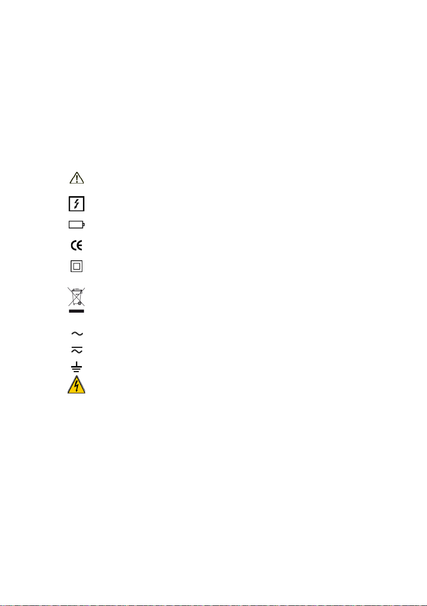
Meanings of the symbols used on the device
Danger. The operator ag rees to ref er to this data sheet whene ver this danger
symbol is encountered.
dangerous voltages.
1.5 V battery.
The CE marking indicates compliance with European directives.
Double insulation or reinforced insulation.
Selective sorti
equipment within the European Union.
In conformity with directive DEEE 2002/96/EC: this equipment must not be
treated as household waste.
AC – Alternating current.
AC and DC – Alternating and direct current.
Earth.
Risk of electric shock.
5
Page 6

Clamp Multimeter METRACLIP 88 English
PRECAUTIONS FOR USE
This device complies with safety standards IEC-61010-1 and 61010-2-032 for
voltages of 1000V in cat egory IV at an altitude OF less t han 2000m , indoors, w it h a
degree of pollution not exceeding 2.
These safety instructions are intended t o ensure the safety of persons and proper
operation of the device. If the tester is used other than as specified in this data
sheet, the protection provided by the device may be impaired.
The operator and/or the responsible authority must c arefully read and clearly
understand the various precautions to be taken in use.
If you use this instrument other than as specified, t he protection it provides
may be compromised, thereby endangering you.
Do not use the instrument in an explosiv e atmosphere or in the presence of
flammable gases or fumes.
Do not use the instrument on networks of which the voltage or category
exceeds those mentioned.
Do not exceed the rated maximum voltages and currents between terminals
or with respect to earth.
Do not use the instrument if it appears to be damaged, incomplete, or not
properly closed.
Before each use, check the condition of the insulation on the leads, housing,
and accessories. Any element of which the insulation is deteriorated (even
partially) must be set aside for repair or scrapped.
Use leads and accessories rated f or voltages and c ategories at least equal to
those of the instrument. If not , an accessory of a lower category lowers t he
category of the combined Clamp + accessory to that of the accessory.
Observe the environmental conditions of use.
Do not modify the instrument and do not replace components with
"equivalents". Repairs and adjustments must be done by approved qualified
personnel.
Replace the batteries as soon as the
unit. Disconnect all cords before opening the battery compartment cover.
Use personal protective equipment when conditions require.
Keep your hands away from the unused terminals of the instrument.
6
symbol appears on the display
Page 7

English Clamp Multimeter METRACLIP 88
When handling the test probes, crocodile clips, and clamp ammeters, keep
your fingers behind the physical guard.
As a safety measure, and to avoid repeat ed overloads on the inputs of the
device, we recommend performing configuration operations only when the
device is disconnected from all dangerous voltages.
MEASUREMENT CATEGO RIES
Definiti ons of t he m e a surement c a t e gories :
CAT II: Circuits directly connect ed to the low-voltage installation.
Example: power supply to household electrical appliances and portable tools.
CAT III: Power supply circuit s in the installation of the building.
Example: distribution panel, circuit-breakers, fixed industrial machines or devices.
CAT IV: Circuits supplying the low-voltage installation of the building.
Example: power lines, meters, and protection devices.
7
Page 8
Clamp Multimeter METRACLIP 88 English
1
3
2
7
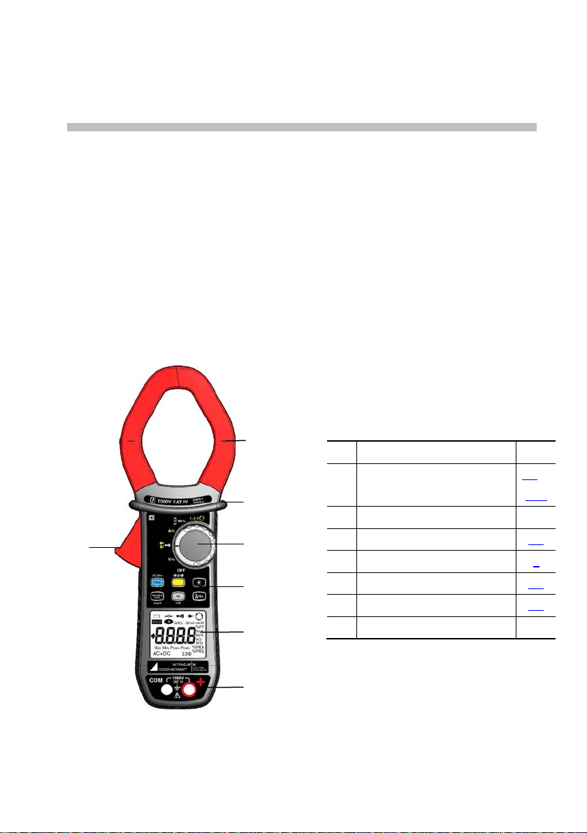
Jaws with centring marks
1 PRESENTATION
The METRACLIP 88 is a professional electrical measuring instrument that
combines the following functions:
Current measurement;
Measurement of inrush current / overcurrent (True-Inrush);
Voltage measurement;
Frequency measurement;
Measurement of level of harmonics (THD)
Continuity test with buzzer;
Resistance measurement;
Diode test;
Power measurements (W, VA, var and PF);
Indication of the order of the phases.
Item
1
(see connection principles)
2 Physical guard 3 Switch 1.1
4 Function keys 2
4
5
5 Display unit 1.3
6 Terminals 1.4
7 Trigger -
Designation See §
3.5 to
3.14
6
Figure 1 : the METRACLIP 88 clamp mult im e t e r
8
Page 9

English Clamp Multimeter METRACLIP 88
1 2 3
4
5
6
1.1 THE SWITCH
The switch has six positions. To access the , , , , , functions,
set the switch to the desired function. Each setting is confirmed by an audible
signal. The functions are described in the table below.
Figure 2 : the switch
Item Function See §
1 OFF mode – Switches the clamp multimeter off 3.3
2 AC, DC, AC+DC voltage measurement (V) 3.5
3 Continuity test
Resistance measurement Ω
Diode test
4 AC, DC, AC+DC current measurement (A) 3.9
5 Power measurements (W, var, VA) and calculation of the
power factor (PF) AC, DC, AC+DC
6
Indicator of the order of the phases 3.12
3.6
3.7
3.8
3.11
9
Page 10
Clamp Multimeter METRACLIP 88 English
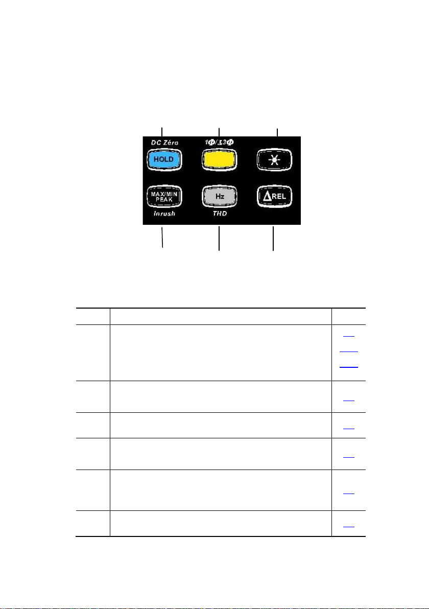
1.2 THE KEYS OF THE KEYPAD
Here are the six keys of the keypad :
1 2 3
4 5 6
Figure 3 : the keys of the keypad
Item Function See §
1 Storage of values, disabling of display
Zero correction A
Compensation of the resistance of the leads in the
continuity and ohmmeter function
2 Selection of the type of measurement (AC, DC, AC+DC)
Selection of single-phase or three-phase measurement
3 Activation or de-activation of the backlighting
of the display unit
4 Activation or de-activation of the MAX/MIN/PEAK mode
Activation or de-activation of the INRUSH mode in A
5 Measurements of frequency (Hz), of the level of harmonics
(THD)
Display of the powers W, VA, var and PF
6 Activation of the ΔREL mode – Display of relative and
differential values
DC/AAC+DC/WDC/WAC+DC
10
2.1
3.9.2
3.6.1
2.2
2.3
2.4
2.5
2.6
Page 11
English Clamp Multimeter METRACLIP 88
Symbol
Designation
AC
Alternating current or voltage
DC
Direct current or voltage
AC+DC
Alternating and direct current or vo ltage
∆REL
Relative value, with respect to a reference
∆Ref
Storage of the values and hold of the display
4
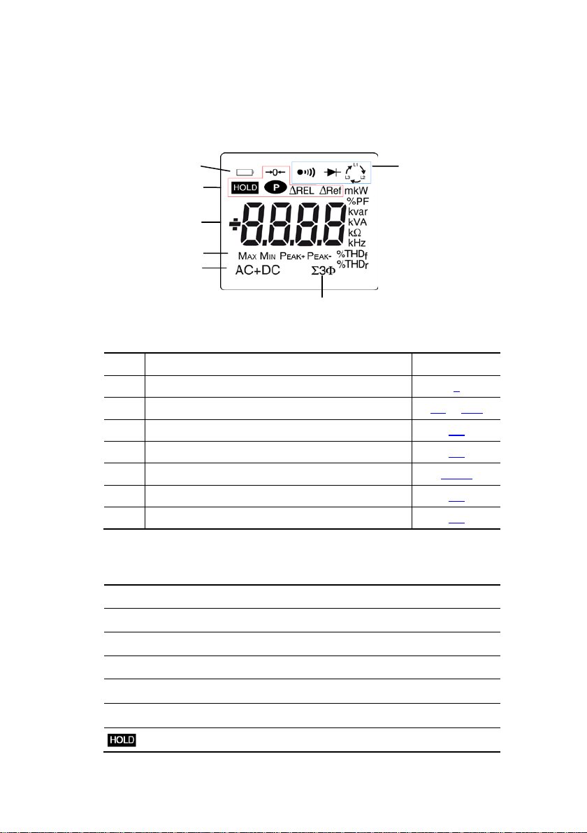
1.3 THE DISPLAY UNIT
Here is the display unit of the cl a mp multimeter:
5
Item Function See §
1 Display of the modes selected (keys) 2
2 Display of the measurement value and unit 3.5 to 3.12
3 Di splay o f the MA X / MIN/PEAK modes 2.4
4 Type of measurement (AC or DC) 2.2
5 Total three-phase power measuremen ts 3.11.2
6 Display of the selected modes (switch) 3.5
7 Spent battery indication 5.2
7
6
1
2
3
Figure 4 : the display unit
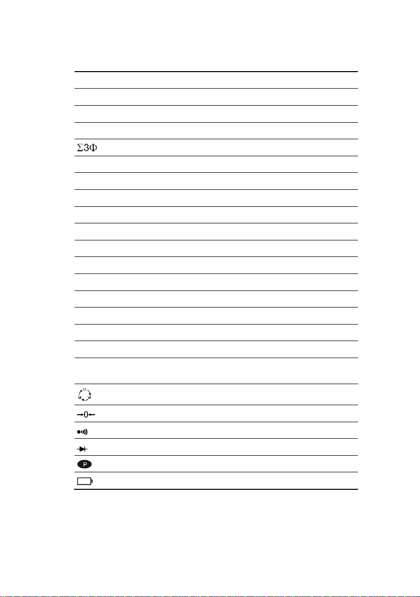
1.3.1 The symbols of the display unit
Reference value
11
Page 12
Clamp Multimeter METRACLIP 88 English
Max
Min
Minimum RMS value
Peak+
Maximum peak value
Peak-
Minimum peak value
Balanced total three-phase power measurement
V
Hz
Hertz
W
Watt
A
Ampere
%
Percentage
Ω
Ohm
m
Milli- prefix
k
Kilo- prefix
var
Reactive power
VA
Apparent power
PF
THDf
Total harmonic distortion with respect to the fundamental
Total harmonic distortion with respect to the true RMS
Compensation of the resistance of the leads
Continuity test
Diode test
Permanent display (automatic switching off de-activated)
Spent battery indicator
Maximum RMS value
Volt
Power factor
THDr
value of the signal.
Indicator of order to the phases
The display of “rdy”, for “ready”, indicates that the device is ready (“Indicator of
order of the phases” function).
1.3.2 Measurement capacity exceeded (O.L)
The O.L (Over Load) symbol is displayed when the display capacity is exceeded.
12
Page 13
English Clamp Multimeter METRACLIP 88
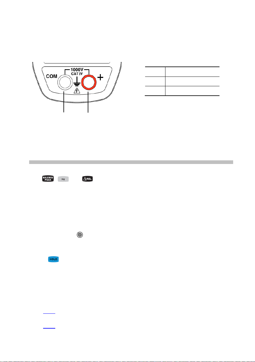
1.4 THE TERMINALS
The terminals are used as follows:
Item Function
1 Cold terminal (COM)
2 Hot terminal (+)
1 2
Figure 5 : the term ina ls
2 THE KEYS
The keys of the keypad respond differently to short, long, and sustained presses.
The
acquisition of parameters complementary to the usual elementary measurements.
- Each of these keys can be used independently of the others or in perfect
complementarity with them: this makes navigation simple and intuitive for
looking up all measurement results.
- It is possible, for example, to look up in turn the MAX, MIN, etc. values of the
RMS voltage alone, or else look up in turn all of t he MAX (or MIN, or PEAK)
values of all power results (W, VA, var, etc.).
In this section, the icon represents the possible positions of the switch for which
the key concerned has some action.
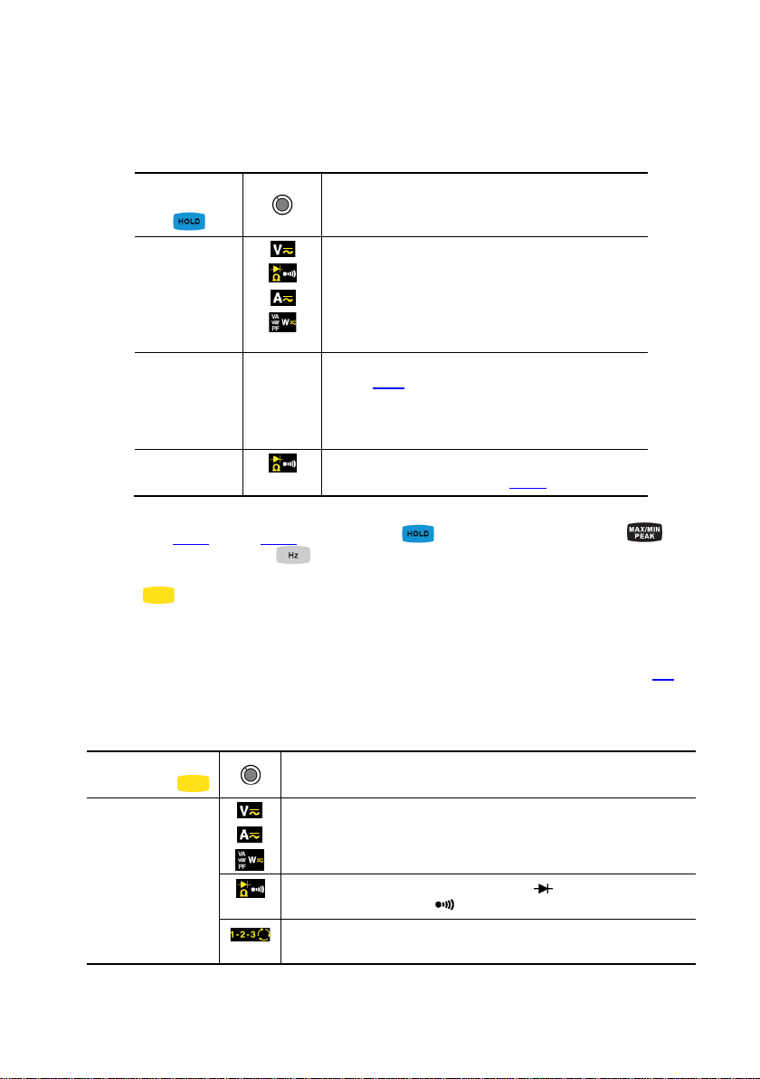
, and keys provide new functions and allow the detection and
2.1
This key is used to:
KEY
store and look up the last values acquired specific to each function (V, A, Ω,
T°) according to the specific modes previously activated (MAX/MIN); the
present display is then maintained while the detection and acquisition of new
values continues;
perform automatic compensation of the resistance of the leads (see also §
3.6.1
3.9.2
) ;
)
AC+DC
et WDC/
(see also §
AC+DC
perform an automatic zero correction in ADC/
13
Page 14
Clamp Multimeter METRACLIP 88 English
ADC
to perform automatic compensation of the
Remark : the key is invalid for the “Indication of order of phases” function.
Successive
presses on
short
Long (>2 sec)
Sustained
A
W
AC+DC
W
AC+DC
1. to store the results of the present
measurements
2. to hold the display of the last value displayed
3. to return to normal display mode (the value of
each new measurement is displayed)
to perform automatic compensation of the zero
(see § 3.9.2
Remark : this mode operates if the MAX/M IN/ PEAK or
DC
HOLD modes (short pres s) are first desactivated
resistance of the leads (see 3.6.1)
… serve
)
See also § 2.4.2 and § 2.5.1 for the action
key with the action of the key
and with the action of the key.
2.2 KEY (SECOND FUNCTION)
This key is used to select the type of measurement (AC, DC, AC+DC) and the
second functions marked in yellow next to the relevant positions of the switch.
It can also be used, in the configuration mode, to modify the default value (see §3.4)
Remark: the key is invalid in the MAX/MIN/PEAK, HOLD and ΔREL modes.
Successive
presses on
short
-to select AC, DC or AC+DC . Depend i ng on your choice, the
screen displays AC, DC or AC+DC
… serve
-to cycle through the Ω and diode test modes and to return
to the continuity test
- to reset the measurement process for the “indicator of order
of rotation of the phases” function.
14
Page 15
English Clamp Multimeter METRACLIP 88
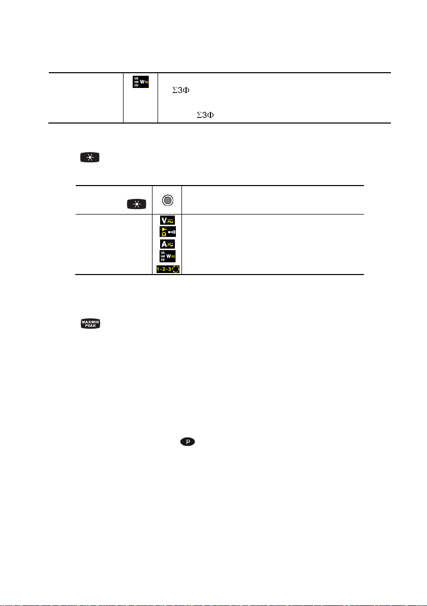
Long (>2 sec)
- to display the total three-phase power of a balanced system
(
is displayed).
- by pressing again, to return to display of the single-phase
power ( is off)
2.3 KEY
This key is used to backlight the display unit.
Successive
presses on
-to activate or de-activate the backlighting of the
screen
… serve
Remark: the backlighting is switched off automatically at the end of 2 minutes.
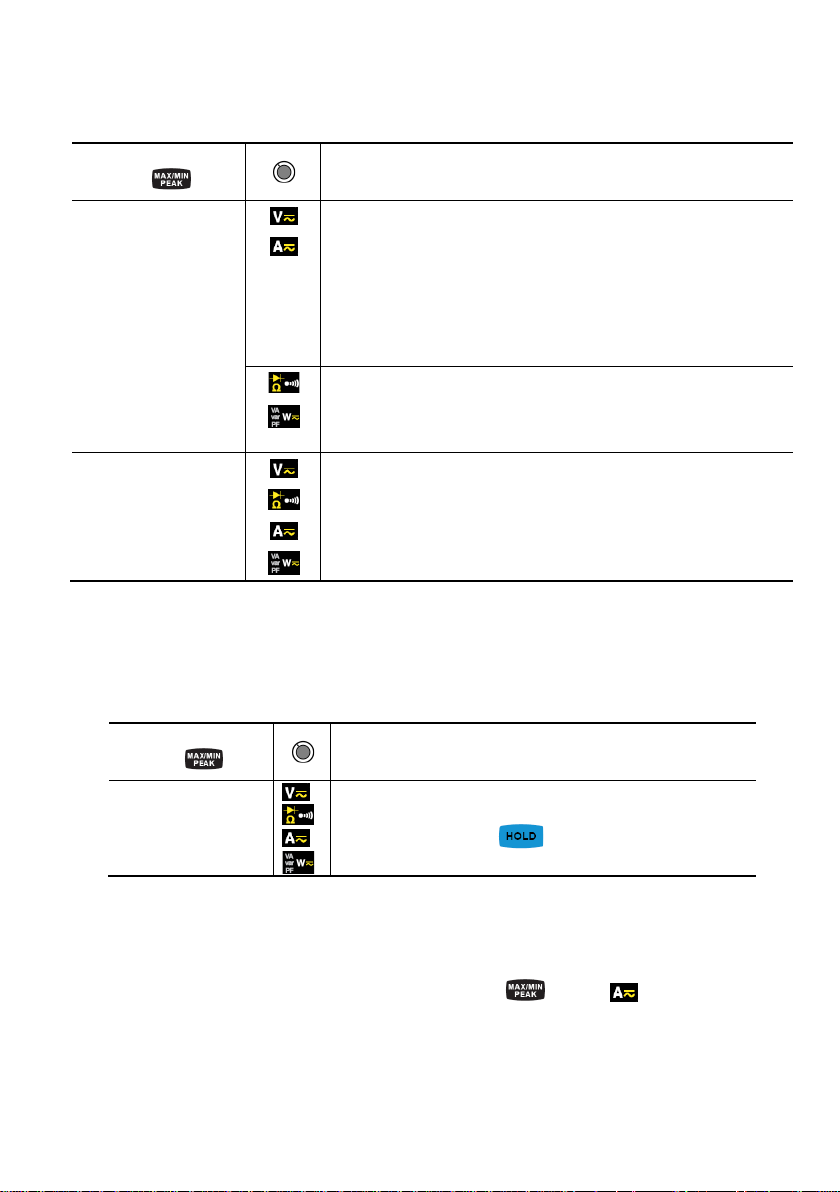
2.4 KEY
2.4.1 In the no rmal mode
This key activates detection of the MAX, MIN, PEAK+ and PEAK- values of the
measurements made.
Max and Min are the extreme mean values in DC and the extre me RM S value s in AC.
Peak+ is the maximum instantaneous peak and Peak- the minimum instantaneous
peak.
Remark : in this mode, the "automatic switching off" function of the device is
automatically de-activated. The
symbol is displayed on the screen.
15
Page 16
Clamp Multimeter METRACLIP 88 English
-to activate detection of the MAX/MIN/PEAK values
from the mode (the values already detected are not erased)
Successive presses
on
long (> 2 sec)
short
-to display the MAX, MIN, PEAK+ or PEAK- value successively
-to return to display of the pre sent measurem ent without e xiting
from the mode (the values already detected are not erased)
Remark: the M AX, MIN, PEAK+, PEAK- symbols ar e b ot h di sp la yed , b ut
only the sym bol of the quantity selected blinks.
Example: If MIN has been selected, MIN blinks and MAX, PEAK+, PEAK-
are lit steadily.
-to activate detection of the MAX/MIN values
-to display the MAX or MIN value successively
-to return to display of the pre sent measurem ent without e xiting
to exit from t he MAX/MIN/PEAK mode. The values pre viousl y
recorded are then erased.
Remark: if the HOL D functi on is ac tiv at ed, it is not pos si ble t o e xit fr om
the MAX/MIN/PEAK mode. T he HOLD function must first be de-activated.
… serve
Remark : ΔREL function can be used with the functions of the MAX/MIN/PEAK
mode.
2.4.2 The MAX/MIN/PEAK mode + activation of the HOLD mode
Successive presses
on
short
to display successively the MAX/MIN/PEAK values
detected before the
… serve
key was pressed.
Note : the HOLD function does not interrupt the acquisition of new MAX, MIN,
PEAK values.
2.4.3 Access to the True-INRUSH mode ( set to )
This key allows measurement of the True-Inrush current (starting current, or
overcurrent in steady-state operation) for AC or DC current only (not operational in
AC+DC).
16
Page 17

English Clamp Multimeter METRACLIP 88
a short press is
been detected.
sequence.
to display:
Successive
presses on
long (>2 sec)
short (<2 sec)
Note:
function al only if an
True-Inrus h value has
to enter the True-INRUSH mode
-"Inrh" is displayed for 3s (the backlighting blinks)
-the triggering threshold is displayed for 5s (the
backlighting is steady);
-"------" is displayed and the "A" symbol flashes
-after detection and acquisition, the inrush
current measurement is displayed, after the
calculations stage "------" (backlighting off)
Remark: the A symbol f lashes to indicate "surveillance"
of t he signal.
to exit from the True-INRUSH mode (return to
simple current measurement).
-to display the PEAK+ value of the current
-to display the PEAK- value of the current
-to display the RMS true-Inrush current
Remark: t he A symbol is displayed steadil y during this
…serves
2.5
KEY
This key is used to display the frequency measurements of a signal, of the power,
and of the level of harmonics.
Remark : this button is not functional in DC.
2.5.1 The Hz function in the normal model
Successive
presses on
short
-the frequency of the signal measured
-the present voltage (V) or current (A)
measurement
17
…serves
Page 18

Clamp Multimeter METRACLIP 88 English
to display:
- the active power (W)
- to select THDf, THDr or the frequency of the
fundamental
-the apparent power (VA)
- the reactive power (var)
- the power factor (PF)
- the frequency of the signal
long
then s hort
- to enter or exit from the level of harmonics
(THD) calculation and display mode
fundamental
2.5.2 The Hz function + activation of the HOLD mode
Successive
presses on
short
-to store the frequency
-to display successively the stored frequency,
then the voltage or the current
- to display in turn the stored values of THDf,
then of THD
…serves
, then of the frequency of the
r
2.6 KEY
This key is used to display and store the reference value or to display the diferential
and relative value, in the unit of magnitude measured or in %.
Remark : in phasis rotation mode, the
key is not operating.
18
Page 19

English Clamp Multimeter METRACLIP 88
Successive
presses on
short
- to enter the ΔREL mode, to store then display the reference
value. The Δ
- to display the diferential value:
- (current value – reference (∆))
The ΔRE L symbo l is di splaye d.
- to display the relative value in %
curr ent value – reference (∆)
Ref symbol is displayed.
…serve
reference (∆)
The ΔREL and % symbols ar e displayed.
- to display the reference. The ΔR e f symb o l i s disp l ayed
- to display the current value. The ΔRef symbol blinks.
long (>2 sec)
to exit from the ΔREL mode
Remark : the “Relative m ode ΔREL” funct ion can be us ed with t he functions of t he
MAX/MIN/PEAK mode.
3 USE
3.1 COMMISSIONING
Insert the batteries supplied with the device as follows:
1. Using a screwdriver, unscrew the screw of the battery compartment cover
(item 1) on the back of the housing and open it.
2. Place t he 4 batteries in the compartment (item 2), taking care to get the
polarities right.
3. Close the battery compartment cover and screw it to the housing.
19
Page 20

Clamp Multimeter METRACLIP 88 English
2
1
Figure 6 : the battery compartment cover
3.2 STARTING UP THE CLAMP MULTIMETER
The switch is set to OFF. T urn the sw itch to t he function of your choice. The whol e
display lights (all symbols) for a few seconds (see §1.3
function chosen is displayed. The clamp multimeter is then ready to make
measurements.
), then the sc reen of t he
3.3 SWITCHING THE CLAMP MULTIMETER
The clamp multimeter can be sw itched off either manually, by set ting the sw itch to
OFF, or automatically, after ten minutes with no action on the switch and/or the
keys. Thirty (30) seconds before the device is switched off, an audible signal
sounds intermittently. To re-activate the device, press any key or turn the switch.
3.4 CONFIGURATION
As a safety measure, and to avoid repeate d overloads on the inputs of the dev ice,
we recommend performing configuration operations only when the device is
disconnected from all dangerous voltages.
20
Page 21

English Clamp Multimeter METRACLIP 88
3.4.1 Programming of the maximum resistance allowed for a continuity
To program the maximum resistance allowed for a continuity
1. From the OFF position , hold the
until the "full screen" display ends and a beep is emitted, to enter the
,
key down while turning the s witch to
configuration mode. The display unit indicates the value below w hich the
buzzer is activated and the
symbol is displayed.
The value stored by default is 40Ω. The possible values lie between 1Ω
and 999Ω.
2. To change the threshold, press the
each press on the
long press (>2s) to the
key increments it. To shift to the next digit, apply a
key.
key. The right-hand digit f lashes:
To exit from the programming mode, turn the switch to another setting. The
detection threshold chosen is stored (emission of a double beep).
3.4.2 De-activation of automatic switching off (Auto Power OFF)
To de-activate automatic switching off:
In the OFF position, hold the
, until the "full screen" display ends and a beep is emitted, to enter the
configuration mode. The
ke y down while t urning the switch to
symbol is displayed.
When the
key is released, the device is in the voltmeter function in
the normal mode.
The return to Auto Power OFF takes place when the clam p is switched
back on.
3.4.3 Programming of the current t hreshold for the True INRUSH measurement
To program the triggering current threshold of the True INRUSH measurement:
1. in the OFF position, hold the key down while turning the switch to
, until the "full screen" display ends and a beep is emitted, to enter the
configuration mode. The display unit indicates the percentage overshoot to
apply to the m easured current to determine the measurement triggering
threshold.
The value stored by default is 10%, represent ing 110% of the established
current measured. The possible values are 5%, 10%, 20%, 50%, 70%,
100%, 150%, and 200%.
21
Page 22

Clamp Multimeter METRACLIP 88 English
2. To change the threshold, press the
press on the
key displays the next value. To record the chosen
threshold, apply a long press (>2s) on the
key. The value flashes: each
key. A confirmation beep is
emitted.
To exit from the programming mode, turn the switch to another setting. The chosen
threshold is stored (emission of a double beep).
Note: The starting current measurement triggering threshold is fixed at 1% of the
least sensitive range. This threshold is not adjustable.
3.4.4 Default configuration
To reset the clamp to its default parameters (factory configurat ion):
In the OFF position, hold the
until the "full screen" display ends and a beep is emitted, to enter the
,
configuration mode. The "rSt" symbol is displayed.
ke y down while t urning the switch to
After 2 s, the clamp emits a double beep, then all of the symbols of the
screen are displayed until the
key is released. The default parameters
are then restored:
Continuity detection threshold =40 Ω
True Inrush triggering threshold =10%
3.5 VOLTAGE MEASUREMENT (V)
To measure a voltage, proceed as follows :
1. Set the switch to
2. Connect t he black lead to the COM terminal and the red lead to "+".
3. Place t he test probes or the croc odile clips on the term inals of the circuit
to be measured. The device selects AC or DC automatically according to
which measured value is larger. The AC or DC symbol lights in blinking
mode.
To select AC, DC or AC+DC manually, press the yellow key to reac h the desired
choice. The symbol corresponding to the choice made then lights in fixed mode.
;
22
Page 23

English Clamp Multimeter METRACLIP 88
The measured value is displayed on the screen.
3.6 CONTINUITY TEST
Warning : Before performing the test, make sure that the circuit is off and any
capacitors have been discharged.
1. Set the switch to ; the symbol is displayed ;
2. Connect t he black lead to the COM terminal and the red lead to «+».
3. Place the test probes or the crocodile clips on the terminals of the
circuit or component to be tested.
An audible signal is emitted if there is continuity, and the measured value is
displayed on the screen.
23
Page 24

Clamp Multimeter METRACLIP 88 English
3.6.1 Automatic compensation of the resistance of the leads
Warning : before the compensation is executed, the MAX/MIN and HOLD modes
must be de-activated.
To perform automatic compensation of the resistance of the leads, proceed as
follows:
1. Short-circuit the leads connected to the device.
2. Hold the
key down until the display unit indicates the lowest
value. The device measures the resistance of the leads.
3. Release the
displayed. The value displayed is stored.
key. The correction and the symbole are
Remark : the correction value is stored only if it is
≤ 2 Ω. Above 2 Ω, the value displayed blinks and is not stored.
3.7 RESISTANCE MEASUREMENT Ω
Warning : Before m aking a resistance measurement, make sure that the circuit is
cold and any capacitors have been discharged.
1. Set the switch to
displayed;
2. Connect t he black lead to the COM terminal and the red lead to « + »;
3. Place the test probes or the crocodile clips on the terminals of the
circuit or component to be measured ;
and press the key. The Ω symbol is
The measured value is displayed on the screen
Remark : t o measure low resistanc e values, first carry out the compensation of the
resistance of the leads (see § 3.6.1
).
24
Page 25

English Clamp Multimeter METRACLIP 88
3.8 DIODE TEST
Warning: Before performing the diode test, make sure that the circuit is cold and
any capacitors have been discharged.
1. Set the switch to and press the key twice. The symbol is
displayed.
2. Connect t he black lead to the COM terminal and the red lead to «+».
3. Place the test probes or the crocodile clips on the terminals of the
component to be tested.
The measured value is displayed on the screen.
3.9 CURRENT MEASUREMENT (A)
The jaws are opened by press ing the trigger on the bod y of the device. The arrow
on the jaws of the clamp (see the diagram below) must point in the presumed
direction of flow of the current, from the generator to the load. Make sure that the
jaws have closed correctly.
Remark: the measurement results are optimal w hen the conductor i s c entred in the
jaws (aligned with the centring marks).
The device automatically selects AC or DC according to which measured value is
larger. The AC or DC symbol blinks.
3.9.1 AC measurement
For an AC current measurement, proceed as follows:
1. Set the switch to
symbol is displayed.
2. Encircle only the conductor concerned with the clamp ;
and select AC by pressing the key. The AC
25
Page 26

Clamp Multimeter METRACLIP 88 English
The measured value is displayed on the screen.
3.9.2 DC or AC+DC measurement
To measure the DC or AC+DC cur rent, if the display unit does not indic ate "0", first
correct the DC zero as follows:
Step 1 : to correc t t he DC ze ro
Important : The clamp must not be closed on the conductor during the DC zero
correction. Hold the clamp in t he same pos ition during the whole pr ocedure so t hat
the correction value will be exact.
Press the
"0". The correction value is stored until the clamp is powered down.
Remark : the correction is effected only if the value displayed is < ± 20 A,
otherwise the value displayed blinks and is not stored. The clamp must be
recalibrated (see §5.3
Step 2 : to make a measurement
1. The switch is set to
2. Appl y the clamp to only the conductor concerned.
key until the devi ce emits a double beep and displays a value near
)
. Select DC or AC+DC b y pressing t he yellow
key until the desired choice is reached.
26
Page 27

English Clamp Multimeter METRACLIP 88
The measurement is displayed on screen.
3.10 STARTING CURRENT OR OVERCURRENT (TRUE INRUSH) MEASUREMENT
Remark : the measurement can be made only in AC or DC mode (AC+DC mode
disabled)
To measure a starting current or overcurrent, proceed as follows:
1. Set the switch to , correct the DC zero (§ 3.9.2), then apply the
clamp around the single conductor concerned.
2. Eff ect a long press on the key. The InRh symbol is displayed,
then the triggering threshold. The clamp then awaits detection of the
True-Inrush current.
"------" is displayed and the "A" symbol flashes.
3. Aft er det ection and acquis ition for 100 ms , the RMS value of t he TrueInrush current is displayed, along with the PEAK+/PEAK- values
subsequently.
4. A long press on the
from the True-Inrush mode.
key or a change of func tion leads to exiting
Remark : t he triggering t hreshold in A is 20A if t he initial current is zero (starting of
installation); it is that set in the configurat ion (see §3.4.3
) for an established current
(overload in a installation).
3.11 POWER MEASUREMENTS W, VA, VAR AND PF
This measurement is possible en single-phase or in balanced three-phase.
Reminder : in DC or AC+DC power measurement, first correct the DC zero in
current (see § 3.9.2
, step 1)
27
Page 28

Clamp Multimeter METRACLIP 88 English
…and the black lead is
connected
…then the clamp is on
the conductor
To the L1 phase
to the L2 phase
of the L3 phase
To the L2 phase
to the L3 phase
of the L1 phase
To the L3 phase
to the L1 phase
of the L2 phase
For the power factor (PF) and the powers VA and var, the measurement is possible
only in AC o r A C+DC.
3.11.1 Measurement of single-phase power
1. Set the switch to and select VA, var, or PF by pres sing the
key until the desired choice is reached;
2. The device automatically displays AC+DC. To select AC, DC, or
AC+DC, press the
key until the desired choice is reached.
3. Connect t he black lead to the COM terminal and the red lead to "+";
4. Place t he test probes or the crocodile c lips of the black lead on the
neutral (N), then those of the red lead on the L phase.
5. Clamp only the corresponding conductor, respecting the direction;
The measurement is displayed on screen.
3.11.2 Balanced three-phase power measurement
1. Set the switch to and select VA, var, or PF by pres sing the
2. Press the yellow key until the
3. The device automatically displays AC+DC. To select AC, DC, or
4. Connect t he black lead to the COM terminal and the red lead to "+";
5. Connect t he leads and the clamp to the circuit as follows:
If the red lead is connected…
key until the desired choice is reached
symbol is displayed.
AC+DC, press the yellow
key until the desired choice is reached.
28
Page 29

English Clamp Multimeter METRACLIP 88
Reminder : the arrow on the jaws of the clamp (see the diagram below) must point
in the presumed direction of flow of the current from the source (producer) to the
load (consumer)
The measurement is displayed on screen.
Remark : You can also measure the three-phase power on a balanced 4-wire
network by proceeding in the same way, or by proceeding as for the measurement
on a single-phase network, then multiplying the value found by three.
“DIRECTION OF ROTATION OF THE PHASES” OR “ORDER OF
3.12
THE PHASES” MODE
This mode is used to determine the order of the phases of a three-phase network
by the "2-wire" method.
To determine the order of the phases, proceed as follows:
Step 1: determination of a "reference" period:
1. Set the switch to . The rdy symbol is displayed; the device is
ready for the first phase order determination measurement;
2. Connect t he black lead with crocodile clip to the COM t erminal and
the red lead with test probe to "+";
3. Connect t he crocodile clip to the presumed L1 phase and apply the
red test probe to the presumed L2 phase;
4. Press the yellow
key. The ref symbol blinks on the screen. The
instrument is ready to determine the reference period. When the
reference period has been determined, an audible signal sounds and
the ref and
symbols are displayed.
Remark : if the reference per iod has not been determined, the dev ice emi ts a beep
and displays the "Err Hz" or "ErrV" message. T he symbol flashes , then the "rdy"
message is displayed on the screen. Repeat the procedure from 4.
29
Page 30

Clamp Multimeter METRACLIP 88 English
Step 2: determination of a "measurement" period:
Within the next 10 seconds, apply the test probe to the presumed L3
phas e. The "MEAS" indication then blinks on the display unit as soon as
t he L2 phase is disconnected; the device is in the calculation phase.
Remark: if the measurement period has not been determ ined, the device emits a
beep and displays the "Err Hz" or "ErrV" message, then "rdy". Repeat the
procedure from 4.
Result: when the order of the phases has been determined, the device emits a
beep and the indication of order of the phases is displayed on the screen, as
follows:
0.1. 2.3 when the directio n of rotation is direct. The "0" symbol blinks and
turns clockwise;
0.3. 2.1 when the direction of rotation is reversed. The "0" symbol blinks
and turns anticlockwise.
Remark: if t he order of the phases has not been determined, the device emits a
beep and displays the "Err" message. Repeat the procedure from 4.
3.13 FREQUENCY MEASUREMENT (HZ)
The frequency measurement is available in V, W and A for AC and AC+DC
quantities. The measurement is based on a count of the passages of the signal
through zero (positive-going edges).
3.13.1 Frequency measurement in voltage
To measure the frequency in voltage, proceed as follows:
1. Set the switch to and press the key. The Hz symbol is
displayed.
2. Select AC or AC+DC b y pressing the yellow
key until the desired
choice is reached.
3. Connect t he black lead to the COM terminal and the red lead to “+”.
4. Place the test probes or the crocodile clips on the terminals of the
circuit to be measured.
30
Page 31

English Clamp Multimeter METRACLIP 88
The measured value is displayed on the screen.
3.13.2 Frequency measurement in current
1. Set the switch to and press the key. The Hz symbol is
displayed.
2. Select AC or AC+DC b y pressing the yellow
key until the desired
choice is reached.
3. Encirc le only the conductor concerned with the clamp.
The measured value is displayed on the screen.
3.13.3 Measurement of frequency in power
In the single-phase AC or AC+DC Power (W) setting, it is possible to display the
frequency of the voltage of the signal on the terminals.
In the balanced three-phase AC or AC+DC Power (W) setting, it is possible to
display the frequency of the phase-to-phase voltage of the signal on the terminals.
31
Page 32

Clamp Multimeter METRACLIP 88 English
3.14 MEASUREMENT OF THE LEVEL OF HARMONICS (THD) AND OF THE FREQUENCY OF THE FUNDAMENT AL (NETWORK)
The device measures the t otal harmonic distortion with res pect to the fundamental
) and the total harmonic distortion with respect to the true RMS value of the
(THD
f
signal (THD
) in voltage and in current. Si milarly, it determ ines the frequenc y of the
r
fundamental by digital filtering and FFT, for netw ork frequencies of 50, 60, 40 0, and
800Hz.
3.14.1 Measurement of the THD and of the frequency of the
fundamental in voltag e
1. Set the switch to and press and hold (>2s) the key. The
THD
symbol is displayed. To select THDr, press the ke y again.
f
The THD
fundamental, press the
2. Connect t he black lead to the COM terminal and the red lead to «+»;
3. Place the test probes or the crocodile clips on the terminals of the
circuit to be measured;
symbol is displayed. To select the frequency of the
r
key again. The Hz symbol is displayed.
The measurement is displayed on screen.
3.14.2 Measurement of the THD and of the frequency of the fundamental in current
1. Set the switch to and press and hold (>2s) the key. The
THD
symbol is displayed. To select THDr, press again. The
f
symbol is displayed. To select the frequency of the fundamental,
THD
r
press the
2. Appl y the clamp to only the conductor concerned.
key again The Hz symbol is displayed.
32
Page 33

English Clamp Multimeter METRACLIP 88
The measurement is displayed on screen.
33
Page 34

Clamp Multimeter METRACLIP 88 English
0.00 V to
99.99 V
100.0 V to
999.9 V
Specified
measurement range
from 0.00V to 9.99V
±(1% R +3 pt)
Resolution
0.01V
0.1V
1V
Input impedance
10MΩ
4 CHARACTERISTICS
4.1 REFERENCE CONDITIONS
Quantities of influence Reference conditions
Temperature: 23°C ±2°C
Relative humidity: 45% to 75%
Supply voltage: 6.0V ±0.5V
Frequency range of the applied signal: 45–65Hz
Sine wave: pure
Peak factor of the applied alternating signal: √2
Position of the conductor in the clamp: centred
Adjacent conductors: none
Alternating magnetic field: none
Electric field: none
4.2 CHARACTERISTICS UNDER THE REFERENCE CONDITIONS
The uncertainties are expressed in ± (x% of the reading (R) + y points (pt)).
4.2.1 DC voltage measurement
Measurement range
Uncertainties
0 to 100% of the measurement range
±(1% R + 10 pt)
from 10.00V to
99.99V
1000 V (1)
±(1% R +3 pt)
34
Page 35

English Clamp Multimeter METRACLIP 88
Measurement
range
0.15 V to
99.99 V
100.0 V to
999.9 V
1000V RMS
1400V peak (1)
Specified
range (2)
from 0.15V to 9.99V
± (1% R +3 pt)
Resolution
0.01V
0.1V
1V
Input impedance
10MΩ
Note (1) - The display i ndicates "+OL" above +2000V and "-OL" below – 2000V in
REL mode
- Above 1000V, a repetitive beep indicates that the voltage being
measured is greater than the safety voltage for which the device is
guaran t eed. The display indicates "OL"
4.2.2 AC voltage measurement
measurement
± (1% R + 10 pt)
Uncertainties
Note (1) - The display indicates "OL" above 1400V (in PEAK mode).
- Above 1000V, a repetitive beep indicates that the voltage being
measured is greater than the safety voltage for which the device is
guaran t eed. The display indicates "OL".
- Bandwidth in AC = 3 kHz
Note (2) Any value between zero and the min. threshold of the measurement range
(0.15V) is forced to "----" on the display.
from 10.00V to
0 to 100% of the measurement range
± (1% R +3 pt)
99.99V
35
Page 36

Clamp Multimeter METRACLIP 88 English
0.15 V to
99.99 V
100.0 V to
999.9 V
1000V RMS (1)
1400V peak
Specified measurement
range
Uncertainties
from 0.15V to 9.99V
± (1% R +3 pt)
Resolution
0.01V
0.1V
1V
Input impedance
10MΩ
4.2.3 AC+DC voltage measurement
Measurement range (2)
0 to 100% of the measurement range
± (1% R+10 pt)
from 10V to 99.99V
± (1% R +3 pt )
Note (1) - The display indicates "OL" above 1400V (in PEAK mode).
- Above 1000V (DC or RMS), a repetitive beep indicates that the voltage
being m easured is greater than t he safety voltage for which the device is
guaranteed.
- Bandwidth in AC = 3 kHz
Note (2) - Any value between zero and the min. threshold of the measurement
range ( 0. 15V) is forced to "----" on the display.
Specific c ha racteris t ic s in MAX/MIN m ode in voltage (from 10 Hz to 1 kHz, in
AC and AC+DC and from 0.30V):
• Uncertainties: add 1% R to the values in the tables above.
Specific character istics in PE AK mode in voltage (from 10 Hz to 400 Hz in AC
and AC+DC):
• Capture time of the extrema: approximately 100ms.
• Uncertainties: add 1.5% R to the values in the tables above.
• PEAK capture time: 1ms min. to 1.5ms max.
36
Page 37

English Clamp Multimeter METRACLIP 88
Measurement
range (2)
0.00 A to
99.99 A
100.0 A to
999.9 A
Specified
range
Uncertainties
until 2000A
± (3.5% R+3 pt)
Resolution
0.01A
0.1A
1A
Measurement range
(2)
0.15 A to
99.99 A
100.0 A to
999.9 A
1000 A to 2000 A
(1)
Specified
measurement range
Uncertainties
± (1% R + 10 pt)
± (1% R +3 pt)
± (1,5% R +3 pt)
Resolution
0.01A
0.1A
1A
4.2.4 DC current measurement
1000 A to 3000 A (1)
Note (1) -The display indicates “+OL" above 6000A and "-OL" below –6000A in
REL m ode. The “-“ and “+” signs are managed (polarity).
Note (2) - The residual current at zero depends on the remanence; It can be
c orr ec t ed by the “DC zero” function of the HOLD key.
4.2.5 AC current measurement
Note (1) - The display indicat es "OL" above 3000A in PEAK mode. The "-" and "+"
signs are not managed.
- Bandwidth in AC = 1 kHz
Note (2) - Any value between zero and the min. threshold of the measurement
range (0.15V) is forced to “----“ on the display.
measurement
(2)
(zero corrected)
± (1% R+10 pt) ± (1% R +3 pt)
- Residual current at zero <150mA.
0 to 100% of the measurement range
± (1.5% R +3 pt)
from 2000A
2500A
± (2.5% R+3 pt)
from 2500A
3000A
0 to 100% of the measurement range
DC:
DC:
DC
DC
to
to
37
Page 38

Clamp Multimeter METRACLIP 88 English
AC: 1000 A to 2000 A
3000 A (1)
Specified
range
Uncertainties
until 2000A
± (3.5% R+3 pt)
Resolution
0.01A
0.1A
1A
4.2.6 AC+DC intensity measurement
Measurement
range (2)
0.15 A to
99.99 A
100.0 A to
999.9 A
DC or PEAK: 1000 A to
Note (1) - In DC, the display indicates "+OL" above +6000A and "+-OL" above 6000A in REL mode. The "-" and "+" signs are managed (polarity).
- In AC and AC+DC, the display indicates "+OL" above 3000A in
PEAK m ode. Th e " -" and "+" signs are not managed.
- Bandwidth in AC = 1 kHz
Note (2) - In AC, any value between zero and the min. threshold of the
m eas u rem ent range (0.15A) is forced to "----" on the display.
- Residual current at zero:
Specific characteristics in MAX/MIN mode in current (from 10 Hz to 1 kHz, in
AC and AC+DC and from 0.30 A):
Specific character istics in P EAK mode in current (from 10 Hz to 400 Hz in AC
and AC+DC):
measurement
(2)
(zero corrected)
•
In DC: depends on the remanence. Can be corrected by the "DC
zero" function of the HOLD key
•
In AC: <150mA
• Uncertainties (zero corrected): add ± (1% R) to t he values in the
tables above.
• Capture time of the extrema: approximately 100ms.
• Uncertainties: add 1.5% R +0.5A to the values in the tables
above.
• PEAK capture time: 1ms min. to 1.5ms max.
0 to 100% of the measurement range
± (1% R+10 pt)
± (1% R +3
pt)
± (1.5% R +3 pt)
DC:
DC
to
from 2000A
2500A
± (2.5% R+3 pt)
from 2500A
3000A
DC:
DC
to
38
Page 39

English Clamp Multimeter METRACLIP 88
Measurement range
20 A to 2000 A AC or 3000 A DC
Specified measurement range
0 to 100% of the measurement range
Uncertainties
± (5% R + 5 pt)
Resolution
1 A
Measurement range
0.0Ω to 999.9 Ω
Open-circuit voltage
≤ 3,6 V
Measurement current
550 µA
Uncertainties
± (1% R +5 pt)
Buzzer triggering threshold
Adjustable from 1Ω to 999Ω (40Ω is the default)
0.0 Ω to
999.9 Ω
1000 Ω to
9999 Ω
10.00 kΩ to
99.99 kΩ
1 to 100% of the
range
Uncertainties
± (1% R +5 pt)
Resolution
0.1Ω
1Ω
10Ω
Open-circuit voltage
≤ 3,6 V
Measurement current
550µA
100µA
10µA
4.2.7 True-Inrush measurement
Specific characte ristics in PE AK mode in True-Inrush (from 10 Hz to 400 Hz in
AC):
• Uncertainties: add ± (1.5% R+0.5A) to the values in the tables above.
• PEAK capture time: 1ms min. to 1.5ms max.
4.2.8 Continui ty me a sure ment
4.2.9 Resistance measurement
Measurement range (1)
Specified measurement
range
Note (1) - Above the maximum display value, the display unit indicates "OL".
- The "-" and "+" signs are not managed.
Specific c ha racteris t ic s in MAX/MIN m ode :
measurement
• Uncertainties: add 1% R to the values of the table above.
• Capture time of the extrema: approximately 100ms.
0 to 100% of the measurement
range
39
Page 40

Clamp Multimeter METRACLIP 88 English
Measurement range
0.000V to 3.199V DC
Specified measurement range
1 to 100% of the measurement range
Uncertainties
± (1% R + 3 pt)
Resolution
0.001V
Measurement current
0.55 mA
Indication: junction reversed or
open-circuit
Display of "OL" when the measured
voltage >3.199V
10.00 kW
99.99 kW
Specified
range
Uncertainties
until 1000A
± (4.5% R+10 pt)
Resolution
1W
10W
100W
1,000W
4.2.10 Diode test
Note : The "-" sign is disabled for the diode test function.
4.2.11 Active DC power measurements
Measurement
range (2)
0 W to
9999 W
to
100.0 kW to
999.9 kW
1000 kW to
3000 kW (1)
measurement
(3)
1 to 100% of the
measurement range
± (2% R +10 pt)
from 1000A to 2000A
± (2.5% R +10 pt)
from 2000A
± (3.5% R+10 pt)
from 2500A
Note (1) - Display of O.L or ± O.L
- Above 3000kW in single-phase (1000V x 3000A).
- Above ±6000kW, in REL mode.
Note (2) - Any applied voltage greater than 1000V causes the emission of an
int er m ittent alarm beep to report a dangerous overload.
Note (3) - The measurement result may be perturbed by an instability linked to the
c urr ent measurement (approximately 0.1A).
2500A
3000A
DC:
DC:
DC
DC
0 to 100% of the measurement range
to
until 1000A
± (2% R +3 pt )
from 1000A to 2000A
± (2.5% R +3 pt)
from 2000A
to 2500A
DC
DC:
± (3.5% R+3 pt)
to
from 2500A
± (4.5% R+3 pt)
to 3000A
DC
DC:
40
Page 41

English Clamp Multimeter METRACLIP 88
10.00 kW
99.99 kW
Specified
range
1 to 100% of the
range
Uncertainties
until 1000A
± (2.5% R +10 pt)
Resolution
1W
10W
100W
1000W
Example: for a power measurement made at 10A, the instability of the
measurement will be 0.1A/10A or 1%.
4.2.12 Active AC power measurements
Measurement
range (2) (4)
5 W to
9999 W
to
100.0 kW to
999.9 kW
1000 kW to
2000 kW (1)
measurement
(3) (7)
measurement
± (2% R +10 pt)
from 1000A to
2000A
0 to 100% of the measurement range
until 1000A
± (2% R +3 pt )
from 1000A to 2000A
± (2.5% R +3 pt)
Note (1) - Display of O.L
- Above 2000kW in single-phase (1000V x 2000A).
- The bandwith is 3 kHz in voltage and 1 kHz in current in AC
Notes (2) and (3) of the previous § apply.
Note (4) - Any power measured less than 5W is r egarded as zero and causes the
display of dashes "----"
- If the voltage is less than 0.15V or if the current is less than 0.15A, the
power measured is regarded as zero and causes the display of dashes "----"
Note 5 - The active powers are positive for power consumed and negative for
power generated.
Note 6 - The signs of the active and reactive powers and power factor are defined
by t he four-quadrant rule below:
- The diagram below sums up the signs of the power as a function of the
phas e ang le between U and I:
Quadrant 1 : Active power P sign + (power consumed)
Quadrant 2 : Active power P sign - (power generated)
Quadrant 3 : Active power P sign - (power generated)
Quadrant 4 : Active power P sign + (power consumed)
41
Page 42

Clamp Multimeter METRACLIP 88 English
10.00 kW
99.99 kW
Specified
range
Uncertainties
until 1000A
± (4.5% R+10 pt)
Resolution
1W
10W
100W
1000W
Note (7) - In balanced three-phases, with deformed signals (THD and harmonics),
uncertainties are guaranted since Ф > 30°. Additionals errors are following ,
depending of THD :
Add +1% for 10% < THD < 20%
Add +3% for 20% < THD < 30%
Add +5% for 30% < THD < 40%
4.2.13 Active AC+DC power measurements
Measurement
range (2) (4)
measurement
(3) (7)
5 W to
9999 W
1 to 100% of the
measurement range
± (2% R +10 pt)
from 1000A to 2000A
± (2.5% R +10 pt)
from 2000 A
2500A
DC:
DC
to
± (3.5% R+10 pt)
from 2500A
3000A
DC:
DC
to
to
100.0 kW to
999.9 kW
0 to 100% of the measurement range
until 1000A
± (2% R +3 pt )
from 1000A to 2000A
± (2.5% R +3 pt)
from 2000A
to 2500A
DC
± (3.5% R+3 pt)
from 2500A
to 3000A
DC
± (4.5% R+3 pt)
1000 kW to
3000 kW (1)
DC:
DC:
Note (1) - Display of O.L
- Above 3000kW in single-phase (1000V x 3000A).
- The bandwith is 3 kHz in voltage and 1 kHz in current in AC
42
Page 43

English Clamp Multimeter METRACLIP 88
Measurement
range (2) (4)
5 VA to
9999 VA
10.00 kVA to
99.99 kVA
100.0 kVA to
999.9 kVA
1000 kVA to
2000 kVA (1)
Specified
range
1 to 100% of the
range
Uncertainties
until 1000A
± (2.5% R +10 pt)
Resolution
1VA
10VA
100VA
1,000VA
10.00 kVA
99.99 kVA
1000 kVA to
(1)
Specified
range
Uncertainties
until 1000A
± (4.5% R+10 pt)
Resolution
1VA
10VA
100VA
1,000VA
Notes (2), (3), (4), 5, 6 and (7) of the previous § apply.
4.2.14 Measurement of apparent AC power
Note (1) - Display of O.L
- Above 2000 kVA in single-phase (1000 V x 2000 A).
- The bandwith is 3 kHz in voltage and 1 kHz in current in AC
Notes (2), (3) and (4) of the previous § apply.
4.2.15 Measurement of apparent AC+DC power
measurement
(3)
Measurement
range (2) (4)
measurement
(3)
measurement
± (2% R +10 pt)
from 1000A to
2000A
5 VA to
9999 VA
1 to 100% of the
measurement range
± (2% R +10 pt)
from 1000A to 2000A
± (2.5% R +10 pt)
from 2000A DC to
2500A DC:
± (3.5% R+10 pt)
from 2500A DC to
3000A DC:
0 to 100% of the measurement range
until 1000A
± (2% R +3 pt)
from 1000A to 2000A
± (2.5% R +3 pt)
to
100.0 kVA to
999.9 kVA
3000 kVA
0 to 100% of the measurement range
until 1000A
± (2% R +3 pt )
from 1000A to 2000A
± (2.5% R +3 pt)
from 2000A DC to 2500A DC:
± (3.5% R+3 pt)
from 2500A DC to 3000A DC:
± (4.5% R+3 pt)
Note (1) - Display of O.L
- Above 3000 kVA in single-phase (1000 V x 3000 A).
43
Page 44

Clamp Multimeter METRACLIP 88 English
10.00 kvar
99,99 kvar
Specified
range
Uncertainties
until 1000A
± (2.5% R +10 pt)
until 1000A
± (2.5% R +3 pt)
Resolution
1 var
10 var
100 var
1 kvar
- The bandwith is 3 kHz in voltage and 1 kHz in current in AC
Notes (2), (3) and (4) of the previous § apply.
4.2.16 Measurement of reactive AC power
Measurement
range (2) (4)
5 var to
9999 var
to
100.0 kvar to
999.9 kvar
1000 kvar to
2000 kvar (1)
measurement
(3) (8)
1 to 100% of the
measurement range
± (2% R +10 pt)
from 1000A to 2000A
0 to 100% of the measurement range
± (2% R +3 pt )
from 1000A to 2000A
Note (1) - Display of O.L
- Above 2000 kvar in single-phase (1000 V x 2000 A).
- The bandwith is 3 kHz in voltage and 1 kHz in current in AC
Notes (2), (3) and (4) of the previous § apply.
Note 5 - In single-phase, the sign of the reactive power is determined by the
phas e l ead or lag between the U and I signs, while in balanced three phas e, it is determined by the calculation on the samples.
Note 6 - Signs of reactive powers according to the four-quadrant rule (§4.2.12):
Quadrant 1 : Reactive power Q sign +
Quadrant 2 : Reactive power Q sign +
Quadrant 3 : Reactive power Q sign Quadrant 4 : Reactive powerQ sign –
Note (8) - In single phase, with deformed signals (THD and harmonics),
uncertainties are guaranted since Ф > 30°. Additionals errors are following ,
depending of THD :
Add +1% for 10% < THD < 20%
Add +3% for 20% < THD < 30%
Add +5% for 30% < THD < 40%
44
Page 45

English Clamp Multimeter METRACLIP 88
10.00 kvar
99.99 kvar
100.0 kvar
999.9 kvar
1000 kvar to
(1)
Specified
range
Uncertainties
until 1000A
± (4.5% R+10 pt)
until 1000A
± (4.5% R+3 pt)
Resolution
1 var
10 var
100 var
1 kvar
Measurement range (1)
-1.00 to +1.00
Specified measurement range
0 to 50% of the
measurement range
50 to 100% of the
measurement range
Uncertainties (7)
± (3% R +3 pt )
± (2% R +3 pt )
Resolution
0.01
4.2.17 Measurement of reactive AC+DC power
Measurement
range (2) (4)
5 var to
9999 var
to
to
3000 kvar
measurement
(3) (8)
1 to 100% of the
measurement range
± (2% R +10 pt)
from 1000A to 2000A
± (2.5% RL +10 pt)
from 2000A DC to 2500A DC:
± (3.5% R+10 pt)
from 2500A DC to 3000A DC:
0 to 100% of the measurement range
± (2% R +3 pt )
from 1000A to 2000A
± (2.5% R +3 pt)
from 2000A DC to 2500A DC:
± (3.5% R+3 pt)
from 2500A DC to 3000A DC:
Note (1) - Display of O.L
- Above 3000 kvar in single-phase (1000 V x 3000 A).
- The bandwith is 3 kHz in voltage and 1 kHz in current in AC
Notes (2), (3) , (4), 5, 6 and (8) of the previous § apply.
Specific characteristics in MAX/MI N m ode in power (from 10Hz to 1kHz):
• Uncertainties: add 1% R to the values in the tables above.
• Capture time: approximately 100ms
4.2.18 Calculation of the power factor
Note (1) - If one of the terms in t he calculation of the power factor i s displayed as
"OL" , or forc ed to zero, the display of the pow er fact or is an indet erminate
v alue " ----".
Note (7) of t he previous § apply.
45
Page 46

Clamp Multimeter METRACLIP 88 English
5.0 Hz to
999.9 Hz
1000 Hz to
9999 Hz
10.00 kHz to
19.99 kHz
1 to 100% of the
range
Uncertainties
± (0.4% R + 1 pt)
Resolution
0.1Hz
1Hz
10Hz
Measurement range (1)
5.0 Hz to 999.9 Hz
Specified measurement range
1 to 100% of the measurement range
Uncertainties
± (0.4% R + 1 pt)
Resolution
0.1Hz
Note 9 - Sign of the power factor according to the four-quadrant rule (§4.2.12):
Quadrant 1 : Power factor PF sign + (inductive system)
Cos Φ sign +
Quadrant 2 : Power factor PF sign - (capacitive system)
Cos Φ sign Quadrant 3 : Power factor PF sign + (inductive system)
Cos Φ sign Quadrant 4 : Power factor PF sign - (capacitive system)
Cos Φ sign +
Specific c ha racteris t ic s in MAX/MIN m ode (from 1 0 Hz to 1kHz):
• Uncertainties: add 1% R to the values in the tables above.
• Capture time: approximately 100ms.
4.2.19 Frequency measurements
4.2.19.1 Characteristics in voltage
Measurement range (1)
Specified measurement
range
4.2.19.2 Characteri sti cs in cu rrent
Note (1) in MAX/MIN mode, the operating range is limited to 1kHz.
- If the level of the signal is too low (<10% of the range, or U<10V or
I<10A) or if the frequency is less than 5Hz, the device cannot determine
the frequency and displays dashes "----".
Specific c ha racteris t ic s in MAX/MIN m ode (from 10Hz t o 1 kHz) :
• Uncertainties: add 1% R to the values of the table above.
• Capture time of the extrema: approximately 100ms.
measurement
46
0 to 100% of the measurement
range
Page 47

English Clamp Multimeter METRACLIP 88
Measurement range
0.0 – 100%
Specified measurement range
0 to 100% of the measurement range
Uncertainties
± (5% R ±2 pts) in voltage
± (5% R ±5 pts) in current
Resolution
0.1%
Measurement range
0.0 – 1000%
Specified measurement range
0 to 100% of the measurement range
Uncertainties
± (5% R ±2 pts) in voltage
± (5% R ±5 pts) in current
Resolution
0.1%
Frequency range
47Hz to 400Hz
Acceptable voltage range
50V to 1,000V
Duration of acquisition of the reference period
≤500ms
Duration of validity of the reference period
information
approximately 10s at 50Hz
approximately 2s to 400Hz
Duration of acquisition of the measurement period
+ display of the order of the phases
Acceptable phase unbalance
±10
Acceptable amplitude unbalance
20%
Acceptable level of harmonics in voltage
10%
4.2.20 Characteristics in THDr
4.2.21 Characteristics in THDf
Note : - The display is "----" if the input signal is too low (U<8V or I<9A) or if the
frequency is less than 5Hz.
Specific characteristics in MAX/MIN m ode in THD (f r o m 1 0 Hz to 1kHz):
• Uncertainties: add 1% R to the values in the tables above.
• Capture time of the extrema: approximately 100ms
4.2.22 Indication of order of the phases
≤500ms
47
Page 48

Clamp Multimeter METRACLIP 88 English
4.3 ENVIRONMENTAL CONDITIONS
Environmental conditions in use in storage
Temperature -20 C to + 55 C -40 °C to + 70°C
Relative humidity (RH): ≤90% at 55°C ≤90% up to 70° C
4.4 CHARACTERISTICS OF CONSTRUCTION
Housing: Rigid polycarbonate shell with moulded elastomer covering
Polycarbonate
Jaws:
Screen:
Dimension: H-296 x W-111 x D-41mm
Weight: 640g ( w it h the batteries)
Opening: 60mm
Clamping diameter: 60mm
LCD display unit
Blue backlighting
Dimension: 41 x 48 mm
4.5 POWER SUPPLY
Batteries: 4x1,5V LR6
Mean life: >350 hours (without backlighting)
Duration of operation before
automati c switching off:
After 10 minutes without action on the switch
and/or keys
4.6 COMPLIANCE WITH INTERNATIONAL STANDARDS
Compliant with standards IEC-61010-1, IEC-61010-2-
Electric safety:
30, and IEC-61010-2-32:
1000V CAT-IV.
48
Page 49

English Clamp Multimeter METRACLIP 88
Quantity of
influence
Range of
influence
Quantity
influenced
Influence
Typical
MAX
Temp
V AC
W DC
1,5%
0,1%R/10°C + 2 pts
0,3%R/10°C + 2 pts
Humidity
V
W
Fr
4%R + 1 pt
Position of the
conductor in the
jaws
(f
Any position on
perimeter of the
A-W
(< 2000A DC or
Adjacent
conductor
carrying a
current of 150 A
DC or RMS
Conductor
perimeter of the
jaws
Conductor
enclosed by the
clamp
Electromagnetic
compatibility:
Mechanical
strength:
Level of protection
of the housing:
Compliant with standard EN-61326-1
Classification: residential environment
Free fall: 2m (in accordance with standard IEC-68-2-32)
Housing: IP54 (per standard IEC-60529)
Jaws: IP40
4.7 VARIATIONS IN THE DOMAIN OF USE
erature -20...+55°C
10%...90%HR
10 Hz...1 kHz
equency
1 kHz... 3 kHz
10 Hz…400 Hz
400 Hz…1 kHz
V DC
A*
Ω
W AC
A
Ω
V
A
0,1%R/10°C
1%R/10°C*
0,15%R/10°C
1%R + 1 pt
8%R + 1 pt
1%R + 1 pt
-
-
-
≤ 1 pt
-
0,2%R
0,25%R
0,1%R/10°C
0,5%R/10°C + 2pts
R/10°C + 2pts*
0,2%R/10°C + 1°C
0,1%R + 1 pt
0,1%R + 2 pts
0,3%R + 2 pts
0,5%R + 2 pts
1%R + 1 pt
9%R + 1 pt
1%R + 1 pt
5%R + 1 pt
≤400 Hz)
the internal
jaws
1400A AC)
(>2000A DC)
2%R
8%L
4%R + 1 pt
touching the
external
0-500 A DC or
RMS
A-W 40 dB 30 dB
V < 1 pt 1 pt
49
Page 50

Clamp Multimeter METRACLIP 88 English
Application of a
voltage of
clamp
Peak factor
1,4 to 3,5
1400 V peak
0-1000 V DC or
the
RMS
A-W
< 1 pt
1 pt
Note * in Temperature : Influence specified until 1000 A DC
limited
to 3000 A peak
A (AC-AC+DC)
V (AC-AC+DC)
1%R
1%R
3%R + 1 pt
3%R + 1 pt
5 MAINTENANCE
The instrument has no parts that can be replaced by personnel who are not trained
and approved. Any non-approved repair or other work, or replacem ent of a part by
an "equivalent", may severely compromise safety.
5.1 CLEANING
Disconnect eve rything connected to the device and set the sw i tch to OFF.
•
Use a soft cloth m oistened with soapy water. Rinse with a damp cloth and
•
dry quickly using a dry cloth or forced air.
Dry perfectly before putting back into use.
•
5.2 REPLACEMENT OF THE BATTERIES
The symbol indicates that the batteries are spent. When this symbol appears
on the display unit, the batteries must be replaced. The measurements and
specifications are no longer guaranteed.
To replace the batteries, proceed as follows:
1. Disconnec t the measurement leads from the input terminals.
2. Set the switch to OFF.
3. Use a sc rew driv er to uns c rew the sc rew s ecuring the batt ery compartment
cover to the back of the housing and open the cover (see §3.1
4. Replace all of the batteries (see §3.1).
5. Close the cover and screw it to the housing.
50
).
Page 51

English Clamp Multimeter METRACLIP 88
5.3 METROLOGICAL CHECK
Like all measuring or testing devices, the instrument must be checked regularly.
This instrument should be checked at least once a year. For checks and
calibrations, contact one of our accredited metrology laboratories (information and
contact details available on request ), at our GOSSEN METRAWATT subsidiary or
the branch in your country.
5.4 REPAIR
For all repairs before or after expiry of warranty, please return the device to your
distributor.
6 WARRANTY
Except as otherwise stipulated, our warrant y is valid for three years starting from
the date on which the equipment w as sold. Extract from our General Conditions of
Sale provided on request.
The warranty does not apply in the following cases:
Inappropriate use of the equipment or use with incompatible equipment;
•
Modificatio ns made to the equipment without the explicit permission of the
•
manufacturer’s technical staff;
W ork done on the device by a person not approved by the manufacturer;
•
Adaptation to a particular application not anticipated in the definition of the
•
equipment or not indicated in the user’s manual;
Damage caused by shocks, falls, or floods.
•
7 DELIVERY CONDITION
The METRACL IP 8 8 clamp multimeter is delivered in its packaging box with :
2 banana-banana leads, one red and one black
•
2 test probes, one red and one black
•
1 black crocodile clip
•
4 1.5 V batteries
•
1 carrying bag
•
the multiligual user manual on mini-CD
•
the multiligual getting started guide
•
51
Page 52

07 - 2013
Code : 692890A02 - Ed. 3
8 ADDRESSES
Repair and Replacement Parts Service
Calibration Center and Rental Instrument Service
If required, please contact:
GMC-I Service GmbH
Service-Center
Thomas-Mann-Strasse 20
90471 Nürnberg • Germany
Phone +49 911 817718-0
Fax +49 911 817718-253
E-Mail service@gossenmetrawatt.com
www.gmci-service.com
This address is only valid in Germany.
Please contact our representatives or subsidiaries for service in other countries.
Product Support
If required, please contact:
GMC-I Messtechnik GmbH
Product Support Hot line
Phone +49 911 8602-0
Fax +49 911 8602-709
E-Mail support@gossenmetrawatt.com
Subject to c hange without notice • A pdf version is available on the Internet
GMC-I Messtechnik GmbH Fax +49 911 8602-777
Südwestpark 15 E-Mail info@gossenmet rawatt. c om
90449 Nürnberg ● Germany www.gossenmetrawatt.com
Phone +49 911 8602-111
 Loading...