

Page 1
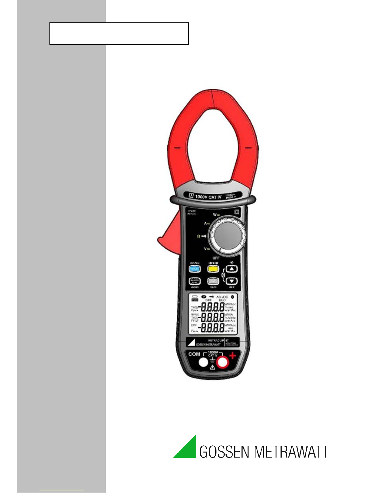
METRACLIP 87
CLAMP MULTIMETER
User’s manual
ENGLISH
Page 2

Clamp Multi me ter METRACLIP 8 7 English
CONTENTS
1
PRESENTATION............................................................................................................ 8
1.1
THE SWITCH ........................................................................................................................................ 9
1.2
THE KEYS OF THE KEYPAD .......................................................................................................... 10
1.3
THE DISPLAY UNIT.......................................................................................................................... 11
1.3.1 The symbols of the display un it ....................................................................... 11
1.3.2 Measurement ca pacity exc e eded (O .L) .......................................................... 13
1.4
THE TERMINALS .............................................................................................................................. 13
2 THE KEYS ..................................................................................................................... 14
2.1
KEY ....................................................................................................................................................... 14
2.2
KEY (
SECOND F UNCT I ON
) ..................................................................................................................... 15
2.3
KEY ....................................................................................................................................................... 15
2.4
KEY ....................................................................................................................................................... 16
2.5
KEY ....................................................................................................................................................... 17
2.5.1 In the normal mode ......................................................................................... 17
2.5.2 Access to the True -INRUSH mode ( set to ) .................................... 18
2.5.3 The MAX/MIN/PEAK mode + activation of the HOLD mode....................... 18
2.6
KEY ....................................................................................................................................................... 19
2.6.1 The Hz function in the normal mode .............................................................. 19
2.6.2 In the display of orders o f harmonics mode or + ................. 20
2.6.3 In Hz mode + activ ation of the HOLD mode ................................................. 20
3 USE .................................................................................................................................. 21
3.1
COMMISSIONING ............................................................................................................................. 21
3.2
STARTING UP THE CLAMP MULTIMETER .............................................................................. 21
3.3
SWITCHING THE CLAMP MULTIMETER .................................................................................. 22
3.4
CONFIGURATION ............................................................................................................................ 22
3.4.1 De-activation of automatic switching off (Auto Power OFF) ....................... 22
3.4.2 Programming of the current threshold for the True INRUSH measurement 22
3.4.3 Program m ing the rat e of reco rd in g in memory ............................................. 23
3.4.4 Erasure of the rec ords in memory .................................................................. 23
3.4.5 Default config uration ...................................................................................... 23
3.5
VOLTAGE MEASUREMENT (V) ................................................................................................... 24
3.6
CONTINUITY TEST ................................................................................................................... 25
3.7
RESISTANCE MEASUREMENT
Ω
................................................................................................ 26
3.8
CURRENT MEASUREMENT (A) ................................................................................................... 26
3.8.1 AC measurement ............................................................................................. 26
3.8.2 DC or AC+DC me asurement.......................................................................... 27
3.9
STARTING CURRENT OR OVERCURRENT (TRUE INRUSH) MEASUREMENT ............. 29
3.10 POWER MEASUREMENTS W, VA,
VAR, PF
AND DPF.............................................................. 30
2
Page 3

English Clamp Multimeter METRA CLIP 87
3.10.1
Measurement of single-phase power .............................................................. 31
3.10.2 Balanced three-ph ase pow e r measu rem ent .................................................... 32
3.10.3 Four quadrant diagram .................................................................................. 33
3.11 ENERGY METERING MEASUREMENT...................................................................................... 33
3.12 FREQUENCY MEASUREMENT (HZ)............................................................................................ 37
3.12.1 Frequency measure ment in voltage ................................................................ 37
3.12.2 Frequency measure ment in current ................................................................ 38
3.13 MEASUREMENT OF THE TOTAL HARMONIC DISTORTION (THD) AND DISPLAY OF
THE ORDERS OF HARMONICS .................................................................................................................... 38
3.13.1 Measurement of the THD in v oltage .............................................................. 38
3.13.2 Measurement of the THD in c urrent .............................................................. 39
3.13.3 Display o f the 25 or ders of ha rmonics a nd of the f requenc y of the
fundamental ..................................................................................................................... 40
3.14 RECORDING OF MEASUREMENT DATA/CAMPAIGNS ....................................................... 41
3.15 PROCESSING OF THE DATA ON A PC WITH THE PAT SOFTWARE .................................. 41
4 CHARACTERISTICS .......................FEHLER! TEXTMARKE NICHT DEFINIERT.
4.1
REFERENCE CONDITIONS ............................................................................................................ 55
4.2
CHARACTERISTICS UNDER THE REFERENCE CONDITIONS ........................................... 55
4.2.1 DC voltage meas urement ................................................................................ 56
4.2.2 AC voltage meas urement ................................................................................ 56
4.2.3 AC+DC voltage m easurement ........................................................................ 57
4.2.4 DC current meas urement ................................................................................ 57
4.2.5 AC current meas urement ................................................................................ 58
4.2.6 AC+DC intensity measurement ...................................................................... 58
4.2.7 True-Inrush mea surement ............................................................................... 59
4.2.8 Calculation of the crest factor ( CF) ............................................................... 59
4.2.9 Calculation of the RIP PLE in D C .................................................................. 60
4.2.10 Continuity meas ure ment ................................................................................. 60
4.2.11 Resista nce measu rement ................................................................................. 60
4.2.12 Active D C power m easuremen ts ..................................................................... 61
4.2.13 Active A C power m easuremen ts ..................................................................... 61
4.2.14 Active A C+DC power measurem ents ............................................................. 62
4.2.15 Measurement of apparent A C power .............................................................. 63
4.2.16 Measurement of apparent A C+DC power ..................................................... 63
4.2.17 Measurement of reactive AC power ............................................................... 64
4.2.18 Measurement of reactive AC+DC power ....................................................... 65
4.2.19 Calculation of the power factor (PF) ............................................................. 65
4.2.20 Calculation of the displac e ment power factor (DPF).................................... 66
4.2.21 Frequency measure ments ................................................................................ 66
4.2.22 Characte ristic s in THDr ................................................................................. 67
4.2.23 Characte ristic s in THDf .................................................................................. 67
4.2.24 Harmonic measurement character istics ......................................................... 67
4.3
ENVIRONMENTAL CONDITIONS ............................................................................................... 68
4.4
CHARACTERISTICS OF CONSTRUCTION ................................................................................ 68
4.5
POWER SUPPLY ................................................................................................................................ 69
3
Page 4

Clamp Multi me ter METRACLIP 8 7 English
4.6
COMPLIANCE WITH INTERNATIONAL STANDARDS ......................................................... 69
4.7
VARIATIONS IN THE DOMAIN OF USE ..................................................................................... 69
5 MAINTENANCE .......................................................................................................... 71
5.1
CLEANING .......................................................................................................................................... 71
5.2
REPLACEMENT OF THE BATTERIES ......................................................................................... 71
5.3
METROLOGICAL CHECK .............................................................................................................. 71
5.4
REPAIR ................................................................................................................................................. 71
6 WARRANTY ................................................................................................................. 72
7 DELIVERY CONDITION ........................................................................................... 72
8 ADDRESSES .................................................................................................................. 73
4
Page 5
English Clamp Multimeter METRA CLIP 87
You have just acquired an METRACLIP 8 7 clamp multimeter and we thank you.
For best results from your device :
• read this user manual attentively,
• observe t h e prec autions for its use.
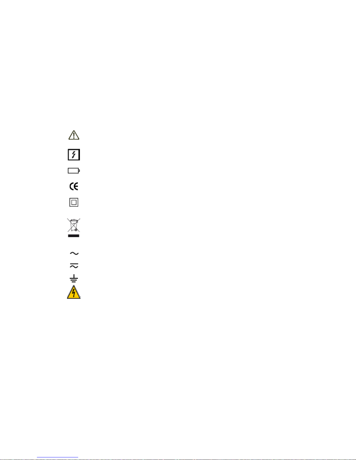
Meanings of the symbols used on the device
Danger. The operat or agrees t o refer to this dat a sheet whene ver this danger
symbol is encountered.
Application or withdrawal authorized on uninsulated or bare conductors at
dangerous voltage s.
1.5 V battery.
The CE marking indicates compliance with European directives.
Double insulation or reinforced insulation.
Selective sorting of wastes for the recycling of electrical and electronic
equipment within the European Union.
In conformity with directive DEEE 2002/96/EC: this equipment must not be
treated as household waste.
AC – Alternating current.
AC and DC – Alternating and direct current.
Earth.
Risk of electric shock.
5
Page 6

Clamp Multi me ter METRACLIP 8 7 English
PRECAUTIONS FOR USE
This device complies with safety standards IEC-61010-1 and 61010-2-032 for
voltages of 1000V in category IV at an altit ude OF les s t han 2000m , indoors, with a
degree of pollution not exceeding 2.
These safety instruct ions are intended to ensure the safety of persons and proper
operation of the device. If the tester is used other than as specified in this data
sheet, the protection provided by the device may be impaired.
The operator and/or the responsible authority must carefully read and clearly
understand the various precautions to be taken in use.
If you use this instrument other than as specified, the protection it provides
may be compromised, thereby endangering you.
Do not use the instrument in an explosive atmosphere or in the presenc e of
flammable gases or fumes.
Do not use the instrument on networks of which the voltage or category
exceeds those mentioned.
Do not exceed the rat ed m axim um v olt ages and current s between terminals or
with respect to earth.
Do not use the instrument if it appears to be damaged, incomplete, or not
properly closed.
Before each use, check the condition of the insulation on the leads, hous ing,
and accessories. Any element of which the insulation is deteriorated (even
partially) must be set aside for repair or scrapped.
Use leads and accessories rated for voltages and cat egories at least equal to
those of the instrument. If not, an accessory of a lower category lowers the
category of the combined Clamp + accessory to that of the accessory.
Observe the environmental conditions of use.
Do not modify the instrument and do not replace components with
"equivalents". Repairs and adjustments must be done by approved qualified
personnel.
Replace the batt eries as soon as the
symbol appears on th e display unit.
Disconnect all cords before opening the battery compartment cover.
Use personal protective equipment when conditions require.
Keep your hands away from the unused terminals of the instrument.
6
Page 7

English Clamp Multimeter METRA CLIP 87
When handling the test probes, crocodile clips, and clamp ammeters, keep
your fingers behind the physical guard.
As a safety measure, and to avoid repeated overloads on the inputs of the
device, we recommend performing configuration operations only when the
device is disconnected from all dangerous voltages.
MEASUREMENT CA TEGORI ES
Definitions of the m e a surem e nt c a t e gories :
CAT II: Circuit s dir ectly connected to the low-voltage installation.
Example: power supply to household electrical appliances and portable tools.
CAT III: Pow er s upply circuit s in the installation of the building.
Example: distribution panel, circuit-breakers, fixed industrial machines or devices.
CAT I V: Circuit s supplying the low-voltage installation of the building.
Example: power lines, meters, and protection devices.
7
Page 8
Clamp Multi me ter METRACLIP 8 7 English
1
3
4
5
6
2
7
1 PRESENTATION
The METRACLIP 87 is a professional electrical measuring instrument that
combines the following functions:
Current measurement;
Measurement of inrush current / overcurrent (True-Inrush);
Voltage measurement;
Frequency measurement;
Measurement of harmonic distortion, total (THD) and order by order;
Continuity test with buzzer;
Resistance measurement;
Power (W, VA, var and PF) and Energy measurements;
Measurement of the Crest Factor (CF), the Displacement Power Factor
(DPF), and RIPPLE;
Recording of data in memory, Wireless data transfer to a PC (by Bluetooth);
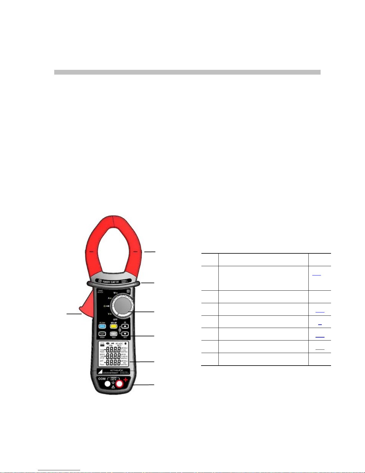
Item
Designation See §
1
Jaws with centring marks
(see connection principles)
3.5 to
3.13
2 Physical guard 3 Switch 1.1
4 Function keys 2
5 Display unit 1.3
6 Terminals 1.4
7 Trigger -
Figure 1 : the ME TRACLIP 8 7 clamp multimeter
8
Page 9
English Clamp Multimeter METRA CLIP 87
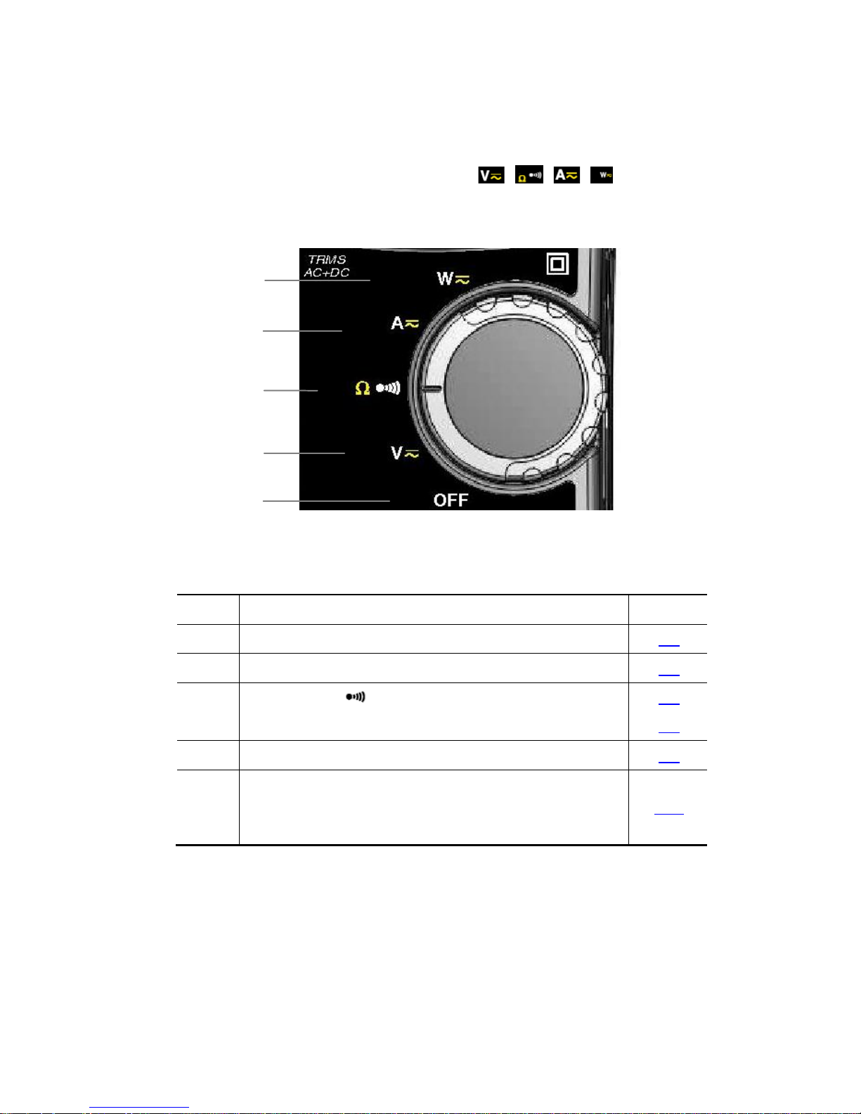
1.1 THE SWITCH
The switch has five positions. To access the , , , , functions, set the
switch to the desired function. Each sett ing is confirmed by an audible signal. The
functions are described in the table below.
Figure 2 : the switch
Item Function See §
1 OFF mode – Switches the clamp multimeter off 3.3
2 AC, DC, AC+DC voltage measurement (V) 3.5
3 Continuity test
Resistance measurement Ω
3.6
3.7
4 AC, DC, AC+DC current measurement (A) 3.8
5 Power measurements (W, var, VA) AC, DC, AC+ DC
Calculation of the power factor (PF), of the displacement
power factor (DPF), of the Energy
3.10
1 2 3
4
5
9
Page 10
Clamp Multi me ter METRACLIP 8 7 English
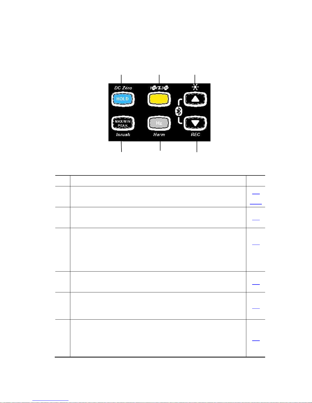
1.2 THE KEYS OF THE KEYPAD
Here are the six keys of the keypad :
1 2 3
4 5 6
Figure 3 : the keys of the keypad
Item Function See §
1 Storage of values, disabling of display
Zero correction ADC/A
AC+DC/WDC/WAC+DC
2.1
3.8.2
2 Selection of the type of measurement (AC, DC)
Selection of single-phase or three-phase measurement
2.2
3 Activation or de-activation of the backlighting
of the display unit
Scrolling up of orders of harmonics or of pages of results in W,
MAX/MIN/PEAK
Activation or de-activation of BT wireless transfer (in combination with 6)
2.3
4 Activation or de-activation of the MAX/MIN mode
Activation or de-activation of the INRUSH mode in A
2.5
5 Measurements of frequency (Hz), of total harmonic distortio n (THD),
and of orders of harmonics
Activation or de-activation of the energy metering mode
2.6
6 Scrolling down of orders of harmonics or of pages of results in W,
MAX/MIN/PEAK
Activation or de-activation of recording of current data in memory
Activation or de-activation of BT wireles s transfer (in combination with 3)
2.4
10
Page 11
English Clamp Multimeter METRA CLIP 87
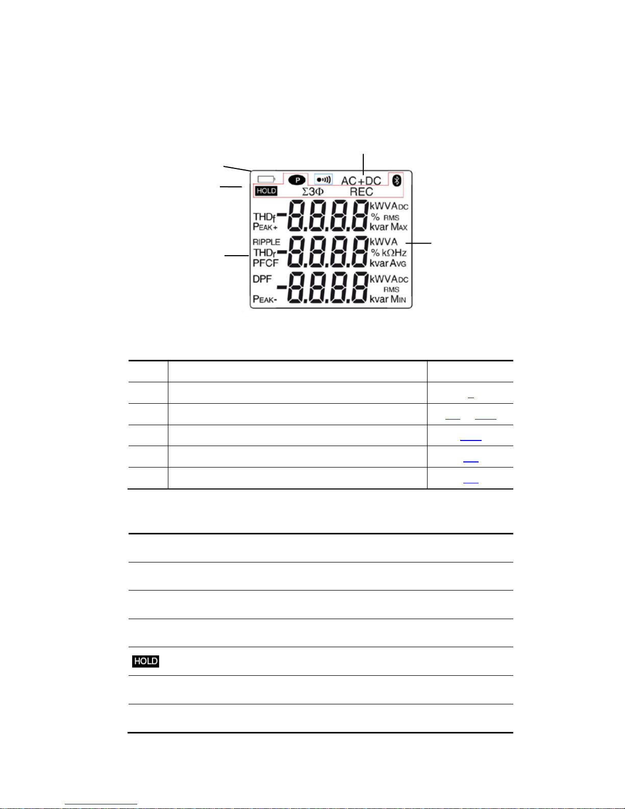
1.3 THE DISPL AY UNIT
Here is the display unit of the clamp multimeter:
Figure 4 : the display unit
Item Function See §
1 Display of the m odes selected (keys) 2
2 Display of the measurement value and unit 3.5 to 3.13
3 Display of the MAX/MIN modes 3.10
4 Type of measurement (AC or DC) 2.2
6 Spent battery indication 5.2
1.3.1 The symbols of the display unit
Symbol Designation
AC Alternating current or voltage
DC Direct voltage
AC+DC Alternating and direct current
Storage of the values and hold of the display
RMS RMS value
Max
Maximum RMS value
1
3
5 2 4
11
Page 12

Clamp Multi me ter METRACLIP 8 7 English
Min Minimum RMS value
AVG Mean RMS value
PEAK+ Maximum peak value
PEAK- Minimum peak value
Balanced total three-phase power measurement
V Volt
Hz Hertz
W Active power
A Ampere
% Percentage
Ω Ohm
m Milli- prefix
k Kilo- prefix
var Reactive power
VA Appare nt power
PF Power factor
DPF Displacelent power factor (cos φ)
CF Crest factor
RIPPLE Ripple (in DC)
THDf Total harmonic distorsion with respect to the fundamental
THDr
Total harmonic distorsion with respect to the true RMS
value of the signal
REC Recording in memory
12
Page 13
English Clamp Multimeter METRA CLIP 87
BlueTooth wireless communication
Continuity test
Permanent display (automatic switching off de-activated)
Spent battery indicator
1.3.2 Measurement capacity exceeded (O.L)
The O.L (Over Load) symbol is displayed when the display capacity is exceeded.
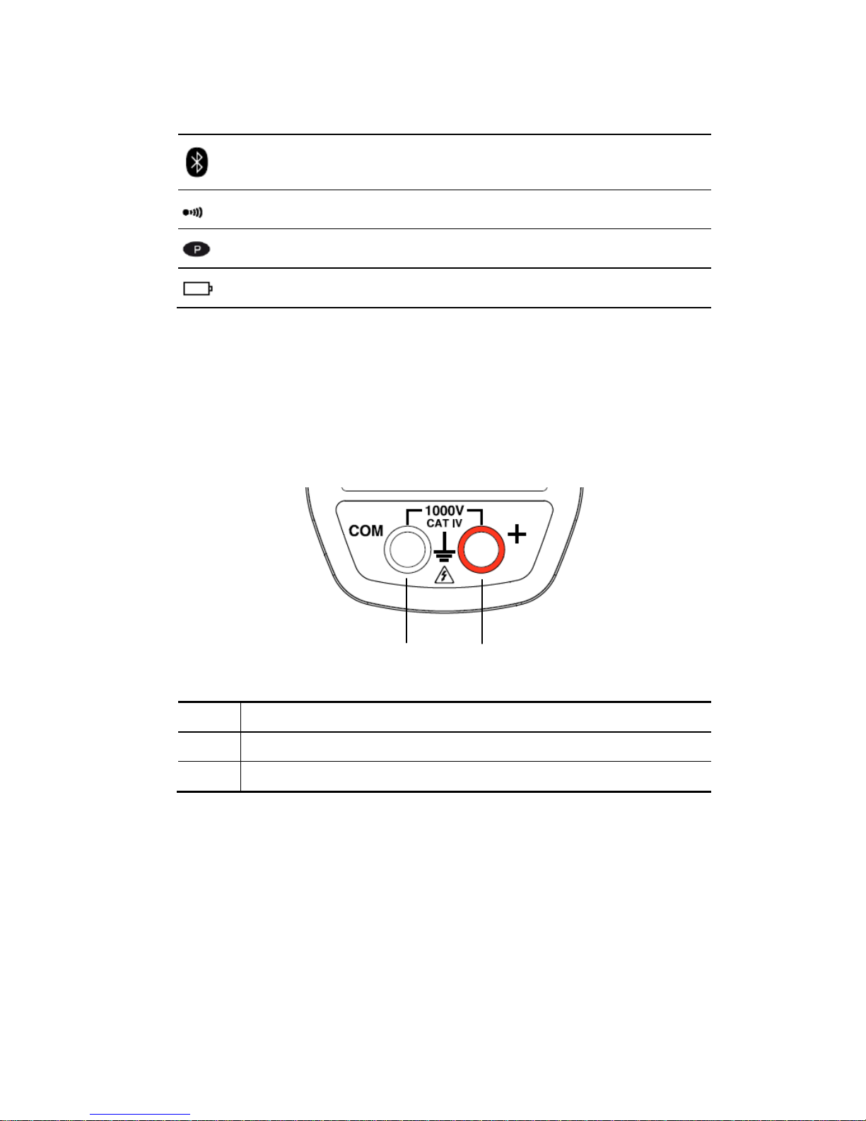
1.4 THE TERMINALS
The terminals are used as follows:
1 2
Figure 5 : the te rminals
Item Function
1 Cold terminal (COM)
2 Hot terminal (+)
13
Page 14
Clamp Multi me ter METRACLIP 8 7 English
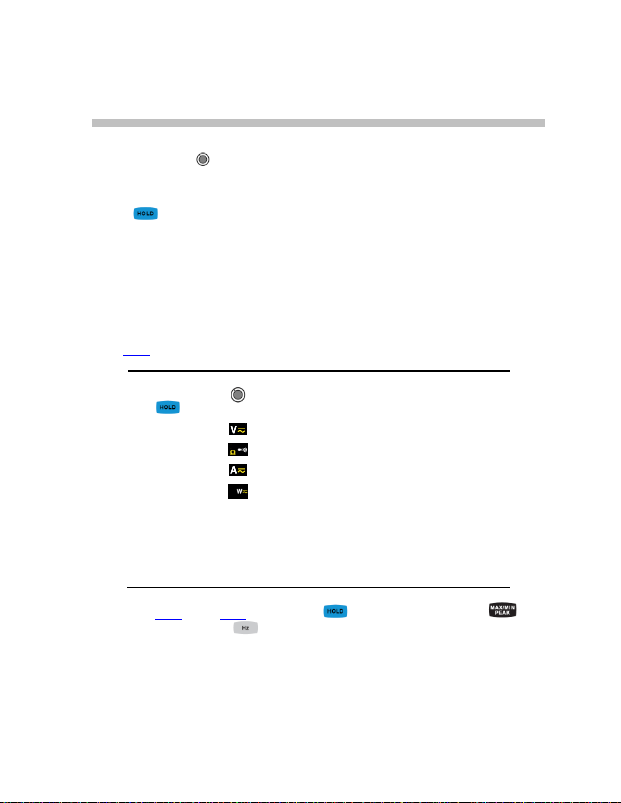
2 THE KEYS
The keys of the keypad respond diff erently to short, long, and sustained presses.
In this section, the
icon represents the possible positions of the switch for which
the key concerned has some action.
2.1
KEY
This key is used to:
store and look up the last values acquired specific to each function (V, A, Ω,
W) according to the specific modes previously activated
(MAX/MIN/PEAK,Hz,THD); the present display is then maintained while the
detection and acquisition of new values continues;
perform an automatic zero correction in A
DC/AC+DC
et WDC/
AC+DC
(see also §
3.9.2
)
Successive
presses on
… serve
short
1. to store the results of the present
measurements
2. to hold the display of the last value displayed
3. to return to normal display mode (the value of
each new measurement is displayed)
Long (> 2 sec) ADC
A AC+DC
WDC
W AC+DC
To perform automatic compensation of the zero
Remark : this mode operates if the
MAX/MIN/PEAK or HOLD modes (short press)
are first desactivated.
See also § 2.5.3 and § 2.6.3 for the action
key with the action of the key
and with the action of the key.
14
Page 15
English Clamp Multimeter METRA CLIP 87
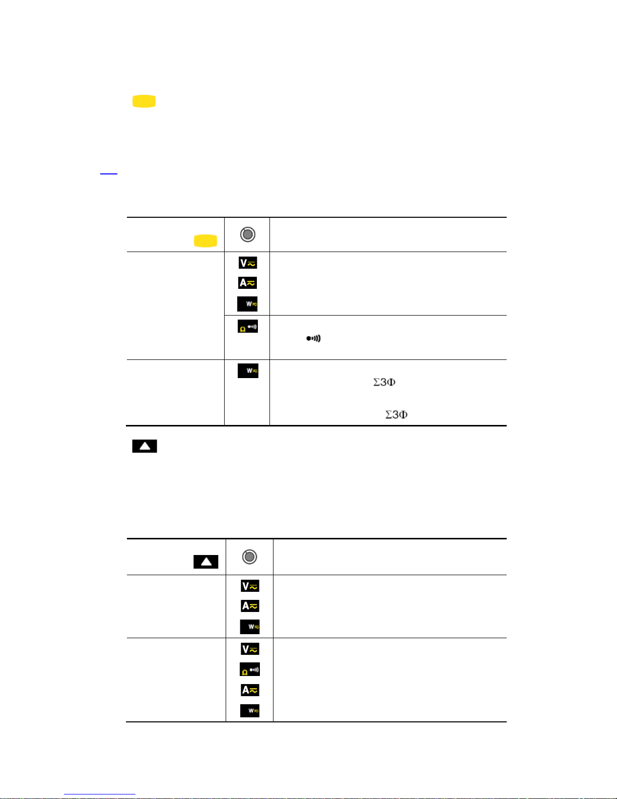
2.2 KEY (SECOND FUNCTION)
This key is used to select the type of measurement (AC, DC, AC+DC) and the
second functions marked in yellow next to the relevant positions of the switch.
It can also be used in the configuration mode, to modify the default values (see
§3.4
)
Remark: the key is invalid in the MAX/MIN/PEAK and HOLD modes.
Successive
presses on
… serve
short
-to select AC, DC or AC+DC. Depending on
your choice, the screen displays AC, DC or
AC+DC
-to cycle through the Ω mode or the continuity
test
Long (> 2 sec)
- to display the total three-phase power of a
balanced system (
is displayed).
- by pressing again, to return to display of the
single-phase power (
is off)
2.3 KEY
This key is used to :
Sc roll orders of harmonics or successive pages up;
Activate the back-lighting;
Activate the Bluetooth function.
Successive
presses on
… serve
short
to scroll through the various pages of
measurement results, depending on the
function and possibly the active mode
(MAX/MIN/PEAK or THD /Harmonics)
long (> 2 sec)
to activate/de-activate the back-lighting of the
display unit.
Remark: the back -lighting is switched off
automat ically at the end of 2 m inutes .
15
Page 16
Clamp Multi me ter METRACLIP 8 7 English
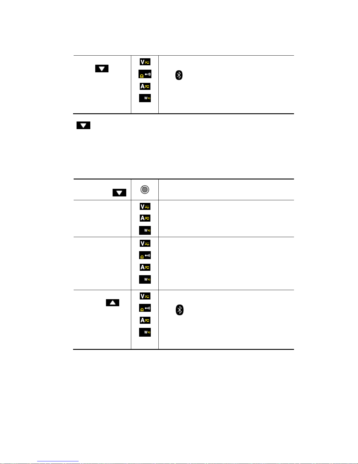
Combined with
the
key
To activate Bluetooth wireless communication.
The
symbol is the displayed.
Remark: activation of the Blueto oth mode
automat ically stops t he recordi ng of the dat a.
2.4 KEY
This key is used to :
Sc roll dow n through the orders of harmonics or successive pages;
Activate the recording of the data;
Activate the Bluetooth function.
Successive
presses on
… serve
short
to scroll through the various pages of
measurement results, depending on the
function and possibly the active mode
(MAX/MIN/PEAK or THD /Harmonics)
long (> 2 sec)
activate/de-activate the recording of the data.
The REC symbol i s then displayed.
Remark: when the r ecording memory is full, the REC
symbol flashes
combiné avec la
touche
To activate Bluetooth wireless communication.
The symbol is then displayed.
Remark: activation of the Blueto oth mode
automatically stops the recording of the data.
16
Page 17
English Clamp Multimeter METRA CLIP 87
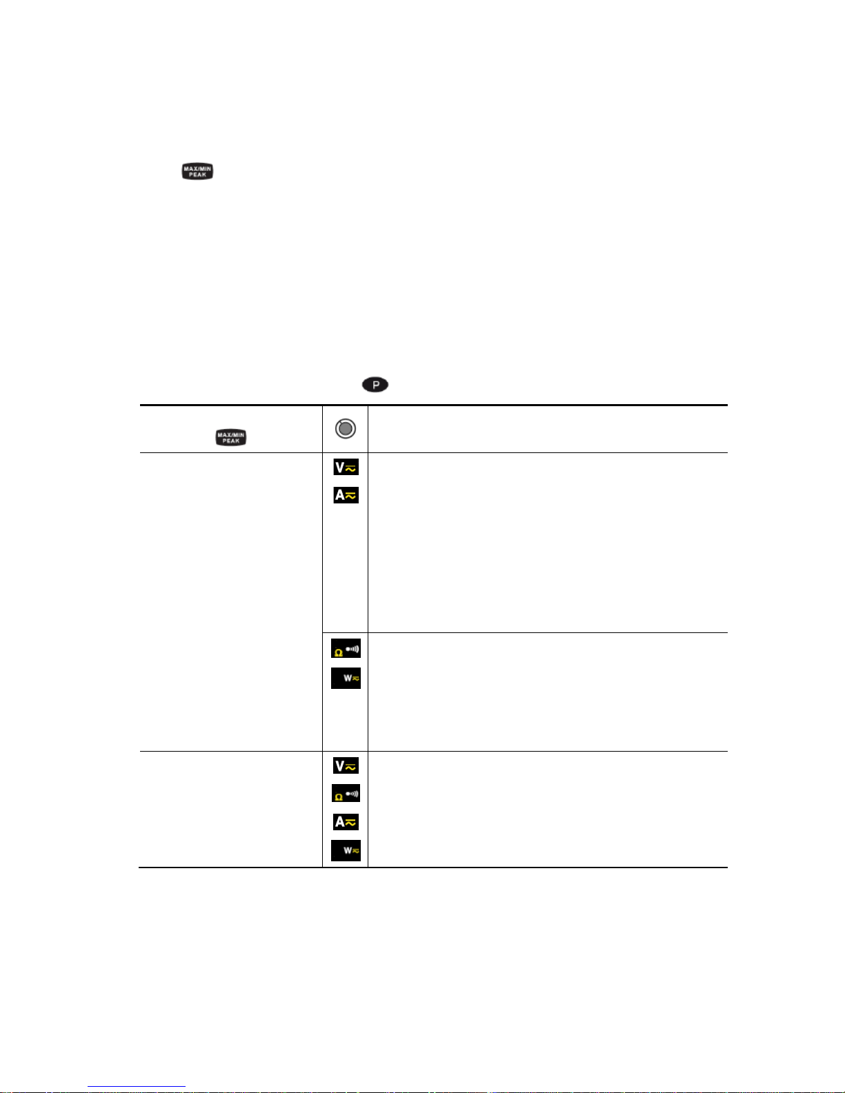
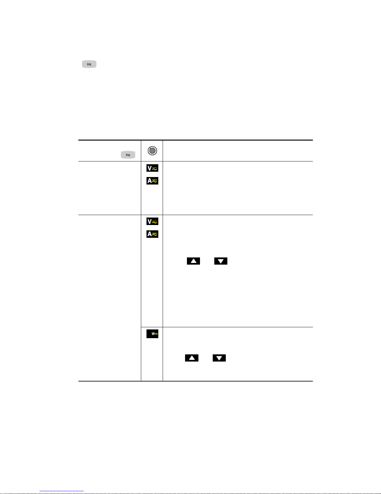
2.5 KEY
2.5.1 In the normal mo de
This ke y activat es detect ion of the MAX, MIN, PEAK+, PEAK- or AVG values of the
measurements made.
Max and Min are the extreme mean values in DC and the extre me RM S values in AC .
Peak+ is the maximum instantaneous peak and Peak- is the minimum i nstantaneous
peak.
AVG is the moving average of 4 mea surements.
Remark : in this mode, the "automatic switching off" function of the device is
automatically de-activated. The
symbol is displayed on the screen.
Successive presses on
… serve
short
-to activate detection of the MAX/MIN/PEAK values
-
to display the MAX, AVG, MIN and PEAK+, AVG,
PEAK- values (on a second screen)
-to return to display of the present measurement
without exiting from the
mode (the values already
detected are not erased)
Remark: dep en d in g on th e m o d e, A C or DC , t h e c r es t f ac t or
(CF), harmonics, frequency, and RIPPLE are also available.
- to activate detection of the MAX/MIN/AVG values.
- to display th e MAX, MIN, and AVG simultaneousl y.
- to return to display of the present measurement
without exiting from the mode (the values already
detected are not erased)
long (> 2 sec)
to exit from the MAX/MIN/PEAK mode. The values
previously recorded are then erased.
Remark: if th e HOLD f unction is acti vated, it is not poss ible
to exit from the MAX/MIN/PEAK mod e. The HOLD f unction
must first be d e-activated.
17
Page 18
Clamp Multi me ter METRACLIP 8 7 English
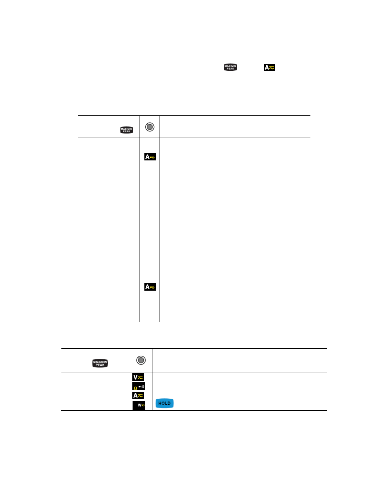
2.5.2 Access to the True-INRUSH mode ( set to )
This key allows measurement of the True-Inrush current (starting current, or
overcurrent in steady-state operation) for AC or DC current only (not operational in
AC+DC).
Successive
presses on
…serves
long (>2 sec)
to enter the True-INRUSH mode
-"Inrh" is displayed for 3s (the backlighting blinks)
-the triggering threshold is displayed for 5s (the
backlighti ng is steady);
-"------" is displayed and the "A" symbol flashes
-after detection and acquisition, the inrush
current measurement is displayed, after the
calculations stage "------" (backlighting off)
Remark: the A symb ol f lashes to indicate "surv eill ance"
of the signal.
to exit from the True-INRUSH mode (return to
simple current measurement).
short (<2 sec)
Note:
a short press is
functi on al only if an
True-Inrush value has
been det ected.
-to display the PEAK+ value of the current
-to display the PEAK- value of the current
-to display the RMS True-Inrush current
Remark: the A sym bol is displayed steadily during this
sequence.
2.5.3 The MAX/MIN/PEAK mode + activation of the HOLD mode
Successive presses
on
… serve
short
to display successively the MAX, AVG, MIN and
PEAK+, AVG, PEAKThe values displayed are the same b
efore the
key was pressed.
Note: the HOLD function does not interrupt the acquisition of new MAX, MIN, PEAK
values
18
Page 19
English Clamp Multimeter METRA CLIP 87
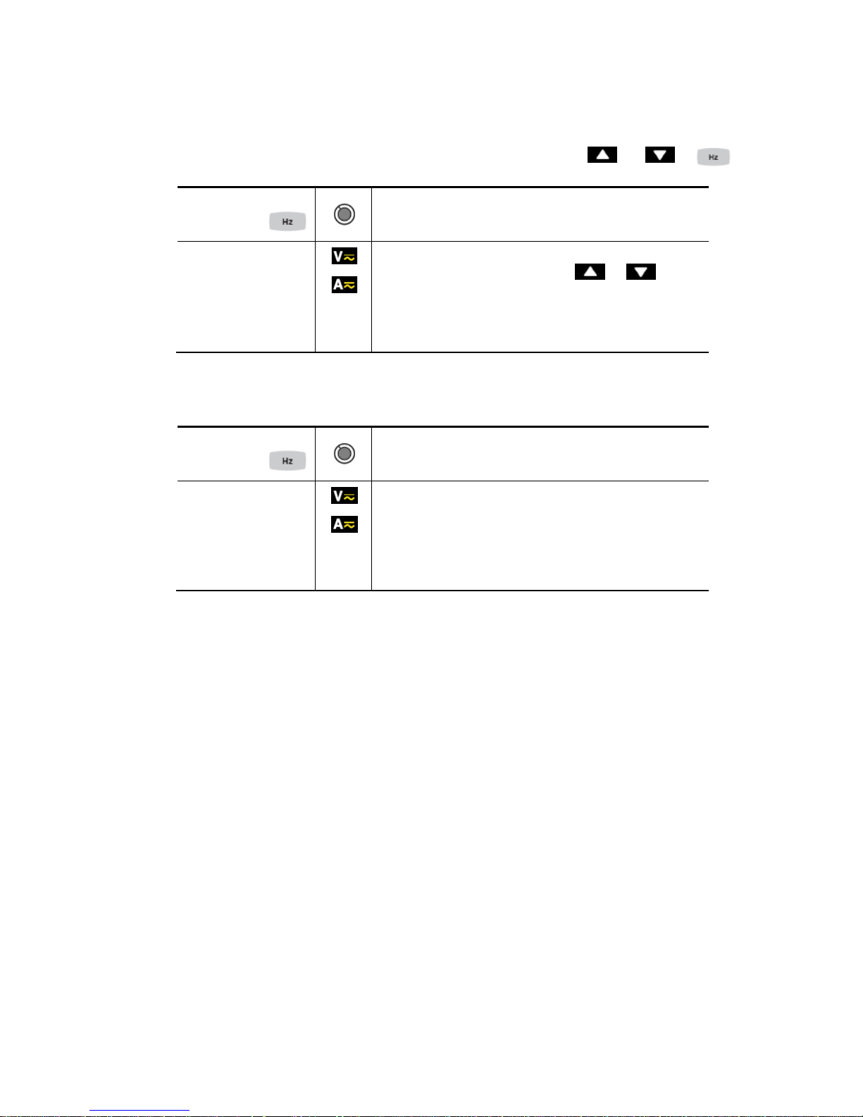
2.6
KEY
This key is used to display measurements of the frequency of a signal, of power, of
the levels and orders of harmonics.
Remark : this key is not working in DC mode.
2.6.1 The Hz function in the normal m ode
Successive
presses on
…serves
short
to di splay:
1. the frequency of the signal, the RMS
measurement, and the DC component
2. the crest factor CF, the RMS measurement,
and the DC component
Long (> 2 sec)
1. to enter or exit from the THD calculation and
display mode
2. to display the THDf, the THDr, and the RMS
value.
3. The and keys are used to display
each order of harmonic (25 orders, from h01 to
h25), with the associated harmonic distortion
(with respect to the fundamental) and the RMS
value of order hxx.
Note: orde r hdC (disp layed i n the DC and
AC+DC modes) is the DC component; order h01
is the fundamental.
1. to activate or stop the energy metering mode
2. to display the various energy parameters
3. The and keys are used to display the
status and energy metering measurement results
pages.
19
Page 20
Clamp Multi me ter METRACLIP 8 7 English
2.6.2 In the display of orders of harmonics mode or +
Successive
presses on
…serve
short
to display the frequency of the order of harmonic
previously selected us ing the or keys,
instead of order hxx.
A 2nd short press restores display of order (hxx)
or hdC
2.6.3 In Hz mode + activation of the HOLD mode
Successive
presses on
…serve
short
To store and display the frequency with the RMS
value and the DC component, then, on a 2nd
consecutive page, the crest factor CF.
Note: the values displayed are those measured
before the HOLD key is pressed
20
Page 21
English Clamp Multimeter METRA CLIP 87
3 USE
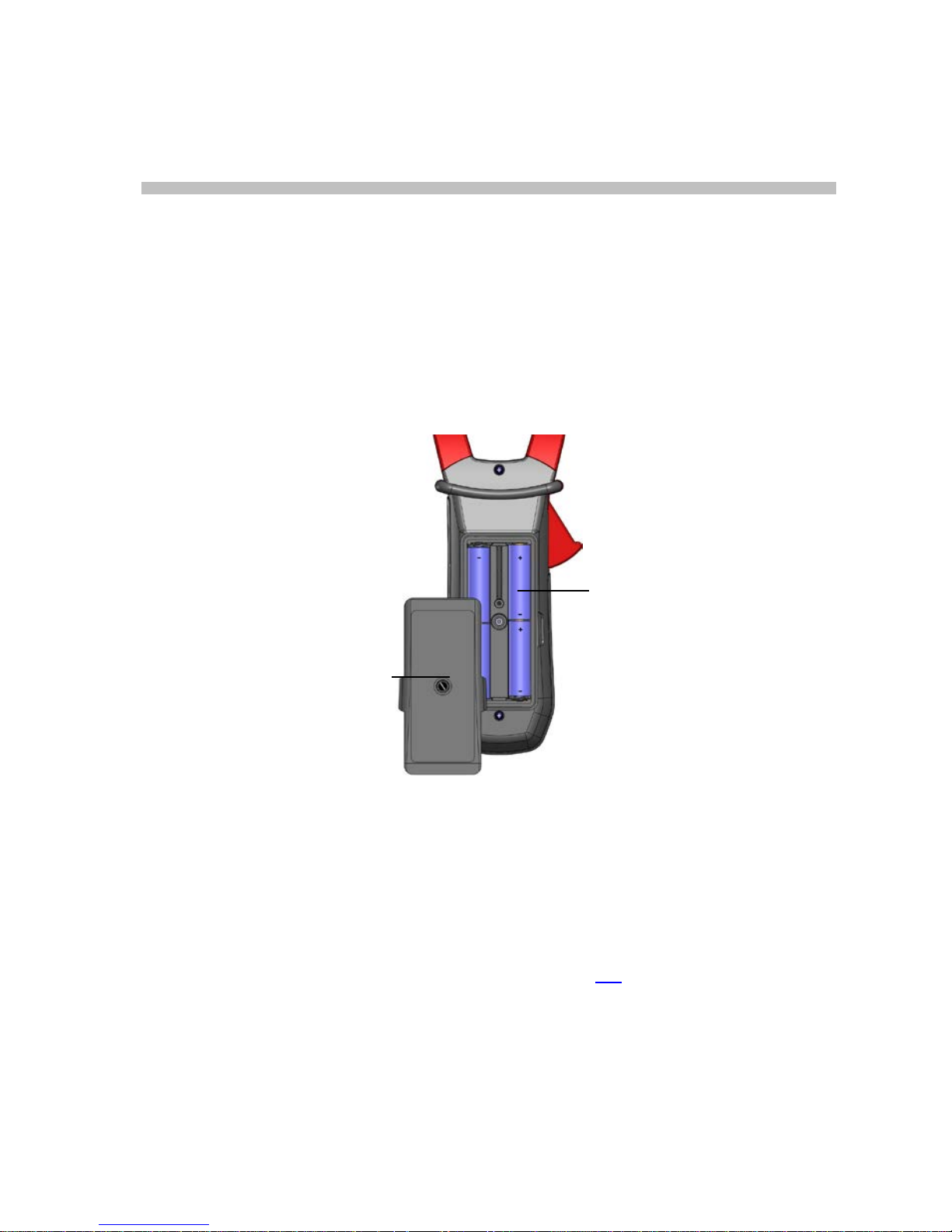
3.1 COMMISSIONING
Insert the batteries supplied with the device as follows:
1. Using a screwdriver, unscrew the screw of the battery compartment cover
(item 1) on the back of the housing and open it.
2. Plac e the 4 batteries in the compartment (item 2), taking care to get the
polarities right.
3. Close t he batt ery compartment cover and screw it to the housing.
Figure 6 : the battery compartment cover
3.2 STARTING UP THE CLAMP MUL TIMETER
The switch is s et to OFF. Turn th e switch t o the funct ion of your choice. T he whole
display lights (all symbols) for a few seconds (see §1.3
), then the screen of the
function chosen is displayed. The clamp multimeter is then ready to make
measurements.
1
2
21
Page 22
Clamp Multi me ter METRACLIP 8 7 English
3.3 SWITCHING THE CLAMP MULTIMETER
The clamp multim eter can be switched off either manually, by setting the s witch to
OFF, or automatically, after ten minutes with no action on the switch and/or the
keys. Thirty (30) seconds before the device is switched off, an audible signal
sounds intermittently. To re-activate the device, press any key or turn the switch.
3.4 CONFIGURATION
As a safety measure, and to av oid repeated overloads on the inputs of the device,
we recommend performing configuration operations only when the device is
disconnected from all dangerous voltages.
3.4.1 De-activation of automatic switching off (Auto Power OFF)
To de-activate automatic switching off:
In the OFF position, hold the
key down while turning the switch to
, until the "full screen" display ends and a beep is emitted, to enter the
configuration mode. The
symbol is displayed.
When the ke y is released, the device is in the voltmeter function in
the normal mode.
The return to Auto Power OFF takes place when the clamp is switched
back on.
3.4.2 Programming of the current threshold for the True INRUSH
measurement
To program the triggering current threshold of the True INRUSH measurement:
1. in the OFF position, hold the
ke y down while turning the switch to
, until the "full screen" display ends and a beep is emitted, to enter the
configuration mode. The display unit indicates the percentage overshoot to
apply to the measured current to determine the measurement triggering
threshold.
Remark : The value stored by default is 10%, representing 110% of the established
current measured. The possible values are 5%, 10%, 20%, 50%, 70%, 100%,
150%, and 200%.
2. To change the threshold, press the
key. The value flashes: each
press on the
key displays the next value. To record the chosen
threshold, apply a long press (>2s) on t he
key. A confirmati on beep is
emitted.
22
Page 23
English Clamp Multimeter METRA CLIP 87
To exit from the programming mode, turn the switch to another setting. The chosen
threshold is stored (emission of a double beep).
Note: The s tarting current measurement triggering threshold is fixed at 1% of the
least sensitive range. This threshold is not adjustable
3.4.3 Programming t he rate of recording in memory
1. In the OFF position, hold the
ke y down while turning the sw itch to
, until t he end of the "f ull sc reen" display and the em ission of a beep,
to enter the configuration mode. The display unit then indicates the
interval of recording of the data in memory.
Remark: the default value is 60 seconds. Possible values range from 1 second to
600 seconds (10 minutes).
2. T o change the re cording interv al, press the
key. The right-hand digit
blinks: each press on the
key increments its value. To go to the next
digit, apply a long press (>2s) to the
key.
When the desired unit is displayed, turn the switch to another setting. The unit
chosen is stored (emission of a double beep).
3.4.4 Erasure of the records in memory
In the OFF position, hold the
key down while turning the switch to
.
The device emits a beep after erasing the records in memory. The "rSt"
and "rEC" symbols are displayed. The device then switches to normal
continuity measurement.
We recommend not having any voltage on the input terminals while doing this.
3.4.5 Default configuration
To reset the clamp to its default parameters (factory configuration):
In the OFF position, hold the
key down while turning the switch to
,
until the "full screen" display ends and a beep is emitted, to enter the
configuration mode. The "rSt" symbol is displayed.
After 2 s, the clamp emits a double beep, then all of the symbols of the
screen are displayed until the
key is released. The default parameters
are then restored:
Recording interval =60 seconds
True Inrush triggering threshold =10%
23
Page 24

Clamp Multi me ter METRACLIP 8 7 English
3.5 VOLTAGE MEASUREMENT (V)
To measure a voltage, proceed as follows :
1. Set the switch to
;
2. Connect t he black lead to the COM terminal and the red lead to "+".
3. Place the test probes or the crocodile clips on the terminals of the circuit to be
measured. The device selects AC or DC automatically according to which
measured value is larger. The AC or DC symbol lights in blinking mode.
To select AC, DC or A C+DC manually, press t he yellow key to reach the desired
choice. The symbol corresponding to the choice made then lights in fixed mode.
The measured values are displayed. :
- in DC
Display Quantity
1st row Voltage V RMS
2nd row DC RIPPLE in %
3rd row DC voltage component, V DC
24
Page 25

English Clamp Multimeter METRA CLIP 87
- in AC and AC+DC
Display Quantity
1st row Total RMS voltage V RMS or TRMS
2nd row Crest factor (CF)
3rd row DC voltage component, V DC
3.6 CONTINUITY TEST
Warning : Before performing the test, make sure that the circuit is off and any
capacitors have been discharged.
1. Set the switch to ; the symbol is displayed ;
2. Connect the black lead to the COM terminal and the red lead to «+».
3. Place the test probes or the crocodile clips on the terminals of the
circuit or component to be tested.
An audible signal is emitted if there is continuity, and the measured value is
displayed on the screen.
25
Page 26

Clamp Multi me ter METRACLIP 8 7 English
3.7 RESISTANCE ME ASUREMENT Ω
Warning : Before making a resistance measurement, make sure that t he circuit is
cold and any capacitors have been discharged.
1. Set the switch to
and press the key. The Ω symbol is
displayed;
2. Connect the black lead to the COM terminal and the red lead to « + »;
3. Place the test probes or the crocodile clips on the terminals of the
circuit or component to be measured ;
The measured value is displayed on the screen
3.8 CURRENT MEASUREMENT (A)
The jaws are opened b y pressing the trigger on t he body of the dev ice. The arrow
on the jaws of the clamp (see the diagram below) must point in the presumed
direction of flow of the current, from the generat or to the load. Make sure that t he
jaws have closed correctly.
Remark: the measur ement res ults ar e optimal w hen the c onductor is c entred in t he
jaws (aligned with the centring marks).
The device automatically selects AC or DC according to which measured value is
larger. The AC or DC symbol blinks.
3.8.1 AC measurement
For an AC current measurement, proceed as follows:
1. Set the switch to
and select AC by pressing the key. T he AC
symbol is displayed.
2. Encircle only the conductor concerned with the clamp ;
26
Page 27

English Clamp Multimeter METRA CLIP 87
The measured values are displayed on the screen.
Display Quantity
1st row RMS current A RMS
2nd row Crest factor (CF)
3rd row DC current component A DC
3.8.2 DC or AC+DC measurement
To measure the DC or AC+DC current, if the dis play unit does not indicate "0", first
correct the DC zero as follows:
Step 1 : to corre c t t he DC ze ro
Important : The clamp must not be closed on the conductor during the DC zero
correction. Hold the clam p in the sam e posit ion during the whole procedur e so that
the correction value will be exact.
Press the
ke y until the device emits a double beep and displays a value near
"0". The correction value is stored until the clamp is powered down.
27
Page 28

Clamp Multi me ter METRACLIP 8 7 English
Remark : the correction is effected only if the value displayed is < ± 10 A,
otherwise the value displayed blinks and is not stored. The clamp must be
recalibrated (see § 5.3
)
Step 2 : to make a measurement
1. The switch is set to . Select DC or AC+DC by pres sing the yellow
key until the desired choice is reached.
2. Apply the clamp to only the conductor concerned.
The measurement values are displayed :
- in DC :
Display Quantity
1st row Current A RMS
2nd row DC RIPPLE in %
3rd row DC current component A DC
28
Page 29

English Clamp Multimeter METRA CLIP 87
- in AC and AC+DC :
Display Quantity
1st row Total RMS current in A RMS or TRMS
2nd row Crest factor (CF)
3rd row DC current component A DC
3.9 STARTING CURRENT OR OVERCURRENT (TRUE INRUSH)
MEASUREMENT
To measure a starting current or overcurrent, proceed as follows:
1. Set the switch to
t hen encircle only the conductor concerned with
the clamp.
2. Effect a long press on the
ke y. The InRh symbol is displayed,
then the triggering threshold. The clamp then awaits detection of the
True-Inrush current.
"------" is displayed and the "A" symbol flashes (central row of the
display).
3. After detection and acquisition for 100 ms, the RMS value of t he TrueInrush current is displayed, along with the PEAK+/PEAK- values
subsequently.
4. A long press on the
key or a change of f unct ion leads to exiting
from the True-Inrush mode.
Remark : the triggering thres hold in A is 10A if the initial current is zero (starting of
installation); it is that set in t he configuration (see §3.4.2) f or an established current
(overload in a installation)..
29
Page 30

Clamp Multi me ter METRACLIP 8 7 English
Display Quantity
1st row “Inrh”
2nd row True Inrush value in A
3rd row Triggering threshold in A
- PEAK display :
Display Quantity
1st row “Inrh”
2nd row PEAK+ or PEAK- value in A
3rd row Triggering threshold in A
3.10 POWER MEASUREMENTS W, VA, VAR, PF AND DPF
This measurement is possible en single-phase or in balanced three-phase.
Reminder : in DC or AC+DC power measurement, first correct the DC zero in
current (see § 3.8.2, step 1)
30
Page 31

English Clamp Multimeter METRA CLIP 87
For the power factor (PF), the displacement power factor (DPF) and the powers VA
and var measurement is possible only in AC or AC+DC.
3.10.1 Measurement of single-phase power
1. Set the swi tch to
;
2. The device automatically displays AC+DC. To select AC, DC, or
AC+DC, press the
key until the desired choice is reached.
3. Connect the black lead to the COM terminal and the red lead to "+";
4. Place the test probes or the crocodile clips of the black lead on the
neutral (N), then those of the red lead on the L phase.
5. Clamp only the corresponding conductor, respecting the direction;.
The measurement value are displayed :
Display Quantity
1st row Active power W (DC, AC or AC+DC)
2nd row Reactive power var (AC or AC+DC)
3rd row Apparent power VA (AC or AC+DC)
31
Page 32

Clamp Multi me ter METRACLIP 8 7 English
3.10.2 Balanced three-phase power measurem en t
1. Set the switch to ;
2. Press the yellow
key until the symbol is displayed.
3. The device automatically displays AC+DC. To select AC, DC, or
AC+DC, press the yellow
key until the desired choice is reached.
4. Connect the black lead to the COM terminal and the red lead to "+";
5. Connect the leads and the clamp to the circuit as follows:
If the red lead is connected…
…and the black lead is
connected
…then the clamp is on
the conductor
To the L1 phase
to the L2 phase
of the L3 phase
To the L2 phase
to the L3 phase
of the L1 phase
To the L3 phase
to the L1 phase
of the L2 phase
Reminder : the arrow on the jaws of the clamp (see the diagram below) must point
in the presumed direction of flow of the current from the source (producer) to the
load (consumer)
The measurement is displayed on screen.
32
Page 33

English Clamp Multimeter METRA CLIP 87
Remark : You can also measure the three-phase power on a balanced 4-wire
network by proceeding in the same way, or by proceeding as for the measurement
on a single-phase network, then multiplying the value found by three.
3.10.3 Four quadrant diagram
In order to determine correctly the signs of the active and reactive powers, we refer
to the diagram below, which determines :
- posit iv e active power (W) = power consumed
- negativ e act ive power = power generated
- react ive power (var) and active power of the same sign = inductive power
- react ive power and active power of opposite signs = capacitive power
3.11 ENERGY METERING MEASUREMENT
The Energy Metering measurement is available in W for the AC and AC+DC
quantities.
The energy meters start and totalize the various types of energy (the eight energy
meters - 4 meters of energy consumed and 4 meters of energy generated - are
started).
To measure the energy metering, proceed as follows:
1. Sst the switch to
;
2. Press the
(long press ). St art-up screen 1 in the Energy Metering
mode appears ;
33
Page 34

Clamp Multi me ter METRACLIP 8 7 English
3. Connecting the black lead to the COM terminal and the red lead to
« + » ;
4. Place the test probes or the crocodile clips of the black lead on the
neutral (N), then those of the red lead on the L phase;
5. Place the clamp around the single conductor concerned, respecting
the direction (see §3.10);
6. To access the metering, press the
key :
The sequence of use is as follows :
I-
---> ---> --->I
I<-------------------------------------|
The statuses of the meters are :
- On <=> metering in operation
- Off <=> met ering stopped (values of the meters 0)
- Stop <=> meterinf stopped (values of the meters preserved)
Hour meter page :
1 : hours (h)
2 : minutes (n)
3 : seconds (s)
34
Page 35

English Clamp Multimeter METRA CLIP 87
The duration of the metering uses the following format: XXXh (for hours) XXm (for
minutes) XXs (for seconds)
N.B. Beyond 999h 59m 59s "---h--m--s " is di s played, but the internal metering
duration keeps running correctly.
View of the set of screens concerning the measurement of Energies by short
presses on
or :
Conventions :
Load designates the energy received by the load or consumed (W+)
Load C designates the capacitive reactive energy (W+ and var-)
Load L designates the inductive reactive energy (W+ and var+)
Supp designates the energy generated by the load (W-)
Supp designates the capacitive reactive energy (W- and var-)
Supp L designates the inductive reactive energy (W- and var+)
35
Page 36

Clamp Multi me ter METRACLIP 8 7 English
7. To access the pages concerning the eneries received by the load
(« Load side »), press the
key ;
The sequence of use is as follows :
I- Load h W ---> Load L h VAR ---> Load C h VAR ---> Load h VA ---> I
I <----------------------------------------------------------------------------------------- I
Example of « LOAD side » screen
8. To access the screens c oncerning t he energies generat ed by the load
and therefore received by the source ("Supply side"), press the
key ;
The sequence of use is as follows :
I - Supp h W ---> Supp L h VAR ---> Supp C h VAR ---> Supp h VA ---> I
I <------------------------------------------------------------------------------------------- |
Example of « SUPP side » screen
The energy displays use the following formats :
- [000.1 ; 999.9]
- [1. 000 k ; 9999 k]
- [10. 0 M ; 999 M]
- [1. 00 G ; 999 G]
36
Page 37

English Clamp Multimeter METRA CLIP 87
3.12 FREQUENCY MEASUREMENT (HZ)
The frequency measurement is available in V, W and A for AC and AC+DC
quantities. The measurement is based on a count of the passages of the signal
through zero (positive-going edges).
3.12.1 Frequency measurement in voltage
To measure the frequency in voltage, proceed as follows:
1. Set the switch to
and press the key. The Hz symbol is
displayed.
2. Select AC by pressing the yellow
key until the desired choic e is
reached.
3. Connect the black lead to the COM terminal and the red lead to “+”.
4. Place the test probes or the crocodile clips on the terminals of the
circuit to be measured.
The measured value is displayed on the screen.
37
Page 38

Clamp Multi me ter METRACLIP 8 7 English
3.12.2 Frequency measurement in current
1. Set the switch to
and press the key. The Hz symbol is
displayed.
2. Select AC or AC+DC by pressing the yellow
key until the desired
choice is reached.
3. Encircle only the conductor concerned with the clamp.
The measured value is displayed on the screen.
3.13 M EASUREMENT OF THE TOTAL HARMONIC DISTORTION
(THD) AND DISPLAY OF THE ORDERS OF HARMONICS
The device meas ures the total harmonic dist ortion with respect to the f undamental
(THDf), the total harmonic distortion with respect to the true RMS value of the
signal (THDr) in voltage and in current, then the level (with respect to the
fundamental), frequency, and RMS value of each order of harmonic.
The frequency of the fundamental is determined by digital filtering and FFT for the
network frequencies of 50, 60, 400, and 800Hz.
3.13.1 Measurement of the THD in voltage
1. Set the switch to
and press and hold (>2s) the key. The
THD
f
, THDr and V RMS symbols are displayed.
2. Connect the black lead to the COM terminal and the red lead to «+»;
3. Place the test probes or the crocodile clips on the terminals of the
circuit to be measured;
38
Page 39

English Clamp Multimeter METRA CLIP 87
The measurement is displayed on screen.
3.13.2 Measurement of the THD in current
1. Set the switch to
and press and hold (>2s) the key. The
THD
f
, THDr and A RMS symbols are displayed.
2. Apply the clamp to only the conductor concerned.
The measurement is displayed on screen.
39
Page 40

Clamp Multi me ter METRACLIP 8 7 English
3.13.3 Display of the 25 orders of harmonics and of the frequency of
the fundamental
In the context of measurem ent of the THDs in voltage ( § 3.13.1) and in current (§
3.13.2) :
1. Press the ke y. Order « hdC » is displayed (DC component), only
in DC or AC+DC. The harmonic s of higher orders are displayed one
by one as the
key is pressed repeatedly. The key can be
pressed to return to the previous order
2. The
ke y can be pressed to display the frequency of t he order of
harmonic concerned ;
40
Page 41

English Clamp Multimeter METRA CLIP 87
3.14 RECORDING OF MEASUREMENT DATA/CAMPAIGNS
The device allows recording of the data/measurements acquired, using the REC
function. The default recording interval is 60 seconds. It can be set to from 1
second to 600 seconds (10 minutes) in set-up (see §3.4.3).
1. In the function being measured, apply a long press (> 2s) t o the
key. The REC symbol is displayed. Recording of the m easurements
starts. The data recorded are in the format: "MAX value – AVG Value
– MIN Value – Unit – Mode" (A C, DC, or AC+DC)
2. To stop recording, apply a long press (>2s) t o the
ke y. The REC
symbol disappears.
Caution : THD recording minimum time interval is 2 s.
Remarks : recording is interrupted automatically when the memory of the device is
full (REC symbol is flashing) or Bluetooth wireless communication is activated
(§3.15)
Type of data Max. number of
records
Max. recording time
at 1s intervals
Max. recording time at
600s intervals (10 mn)
V, A, Ω
3000
16 minutes
160 hours
W
3000
3.5 minutes
35 hours
THD 3000
11 minutes
(interval 2 s)
55 hours
Harmonics
3000
8 minutes
80 hours
3.15 PROCESSING OF THE DATA ON A PC WITH THE PAT
SOFTWARE
The device allows wireless transfer of recorded data/measurements (§3.14) to a
PC, by means of the Bluetooth function.
The Bluetooth connection must first hav e been prepared on the PC, which must be
on standby.
In the active measurement function, press the
and ke ys sim ultaneously.
The
symbol is displayed. The PC must recognize the device and connect to it :
41
Page 42

Clamp Multi me ter METRACLIP 8 7 English
1. Example of process with Windows XP : Activate the connection
Blue-Tooth
1.1 The device was recognized by the PC (METRACLIP 87 on port
COM41 in this example) :
42
Page 43

English Clamp Multimeter METRA CLIP 87
1.2 The device is going to connect with the PC : choose « Connect »
43
Page 44

Clamp Multi me ter METRACLIP 8 7 English
1.3 The device is connected with the PC, after entering password
« 0000 » :
1.4 Device connection in progress with PAT software, wi th Bluetooth
44
Page 45

English Clamp Multimeter METRA CLIP 87
2. Example of process with Windows 7 : choose « Blue-Tooth »
symbol and after « Add a device »
Remark : if the « Blue-Tooth » symbol is not displayed, go to Windows
menu and choose « Devices and Printers ». Choose after « Add a
device ».
2.1 The device was recognized by the PC (F607 in this example) :
when the device is detected, choose it and choose after « Next ».
45
Page 46

Clamp Multi me ter METRACLIP 8 7 English
Choose « Associa te wi th o ut using th i s code ».
Choose « Next » for connection acceptance.
2.2 The device is going to connect with the PC : choose « Close »
46
Page 47

English Clamp Multimeter METRA CLIP 87
To check the detection, it is necessary to display the « Blue-Tooth » devices.
Choose « right clic » in the « Blue-Tooth » symbol and choose « Display BlueTooth devices».
Then choose « Properties » of the device detected by Blue-Tooth (right clic).
47
Page 48

Clamp Multi me ter METRACLIP 8 7 English
1) In the « Matérial » folder, the port COM num ber dedicated to the device is
displayed (COM18 in the example).
2) Under the Bluetooth tab
you can assign your own
designation
(e. g. ME TRACLIP 87 )
instead of the default product
ID (here : F607).
1)
2)
48
Page 49

English Clamp Multimeter METRA CLIP 87
2.3 Device connection in progress with PAT software, wi th Bluetooth.
Choose only « Port COM » to communicate, and choose the
good port COM (COM18 here)
When launching connection, a Windows message prevent a Blue-Tooth connection
want to esta b l ish :
When choose this message, a windows is displayed to ask device PIN code. You
must enter « 0000 ». Then choose « Next » to validate the connection.
A connect ion is established via a Bluetooth device.
Clic k here to enable.
49
Page 50

Clamp Multi me ter METRACLIP 8 7 English
Validate by choosing « Close »
50
Page 51

English Clamp Multimeter METRA CLIP 87
In PAT software, the connection is established. All the informations of the device
are displayed in the following windows.
Remark : this process must be made only at the first connection. Parameter are
stored in the PC for next connections.
3. Data recorded must be used with the PAT software.
3.1 The device is connected. Display the records stored in the device.
Select the record to be transferred.
51
Page 52

Clamp Multi me ter METRACLIP 8 7 English
3.2 Transfert of the selected record from the device to PAT software.
3.3 The data are recovered in PAT software. Display of the data in
Text mode, in the format « date – time – MIN – AVG – MAX ».
Nota : MAX,AVG and MIN values are calculated with values measu red bet ween 2
records spaced with record interval value.
52
Page 53

English Clamp Multimeter METRA CLIP 87
3.4 Display of the same data in Graph mode.
3.5 Graph m ode enlarged/zoomed.
53
Page 54

Clamp Multi me ter METRACLIP 8 7 English
3.6 Data are exported to Excel software.
3.7 To us e the files recorded by PAT software on the PC : PAT
generate a folder « Dataview\Datafiles\METRACL IP 87 F607 »
were Excel files are stored.
54
Page 55

English Clamp Multimeter METRA CLIP 87
3.16 REFERENCE CONDITIONS
Quantities of influence Reference conditions
Temperature: 23°C ±2°C
Relative humidity: 45% to 75%
Supply voltage: 6.0V ±0.5V
Frequency range of the applied signal: 45–65Hz
Sine wave: pure
Peak factor of the applied alternating signal: √2
Position of the conductor in the clamp: centred
Adjacent conductors: none
Alternating magnetic field: none
Electric field: none
3.17 CHARACT ERISTICS UNDER THE REFERENCE CONDITIONS
The uncertainties are expressed in ± (x% of the reading (R) + y points (pt)).
55
Page 56

Clamp Multi me ter METRACLIP 8 7 English
3.17.1 DC voltage measurement
Measurement range
0.00 V to
99.99 V
100.0 V to
999.9 V
1000 V (1)
Specified
measurement range
0 to 100% of the measurement range
Uncertainties
from 0.00V to 9.99V
±(1% R + 10 pt)
from 10.00V to
99.99V
±(1% R +3 pt)
±(1% R +3 pt)
Resolution
0.01V
0.1V
1V
Input impedance
10MΩ
Note (1) Above 1000V, a repetitive beep indicates that the voltage being
measured is greater than the safety voltage for which the device is guaranteed. The
display indicates "OL"
3.17.2 AC voltage measurement
Measurement
range
0.15 V to
99.99 V
100.0 V to
999.9 V
1000 V RMS
1400 V peak (1)
Specified
measurement
range (2)
0 to 100% of the measurement range
Uncertainties
from 0.15V to 9.99V
± (1% R + 10 pt)
from 10.00V to
99.99V
± (1% R +3 pt)
± (1% R +3 pt)
Resolution
0.01V
0.1V
1V
Input impedance
10MΩ
Note (1) -Above 1000V, a repetitive beep indicates that the voltage being measured
is greater than the s afety voltage for which the device is guaranteed. The display
indicates "OL".
- Bandwidt h i n AC = 3 kHz
Note (2) Any value between zero and the min. threshold of the measurement range
(0.15V) is forced to "----" on the display
56
Page 57

English Clamp Multimeter METRA CLIP 87
3.17.3 AC+DC voltage measurement
Measurement range (2)
0.15V to
99.99V
100.0V to
999.9V
1000V RMS MAX
(1)
1400V peak
Specified measurement
range
0 to 100% of the measurement range
Uncertainties
from 0.15V to 9.99V
± (1% R+10 pt)
from 10V to 99.99V
± (1% R +3 pt)
± (1% R +3 pt)
Resolution
0.01V
0.1V
1V
Input impedance
10MΩ
Note (1) - The dis play indicates "OL" above 1400V (in PEAK mode).
- Above 1000V (DC or RMS), a repetitive beep indicates that the voltage
being measured is great er than the safety voltage for which the dev ice is
guaranteed.
- Bandwidth in AC = 3 kHz
Note (2) - Any value between zero and the min. threshold of the measurement
range (0.15V) is forced to "----" on the display.
- Specific chara cterist ics in MAX/ MIN mode i n tension (f rom 10 Hz to 1 kHz in
AC and AC+ DC):
• Uncertainties: add 1% L to the values in the tables above.
• Capture time of the extrema: approximately 100ms.
- Specific cha racteristics in PEAK mode in tension (from 10 Hz to 400 Hz in AC
and AC+DC):
• Uncertainties: add 1.5% L to the values in the tables above.
• PEAK capture time: 1ms min. to 1.5ms max.
3.17.4 DC current measurement
Measurement
range
0.00A to
99.99A
100.0A to
999.9A
1000A to 1500A (1)
Specified
measurement
range
0 to 100% of the measurement range
Uncertainties
(2)
(zero corrected)
± (1% R+10 pt) ± (1% R +3 pt)
57
Page 58

Clamp Multi me ter METRACLIP 8 7 English
Resolution
0.01A
0.1A
1A
Note (1) - The display indicates “+OL" above 1500A .
Note (2) - The residual current at zero depends on the remanence; It can be
corrected by the “DC zero” function of the HOLD key.
3.17.5 AC current measurement
Measurement
range (2)
0.15 A to
99.99 A
100.0 A to
999.9 A
1000 A (1)
Specified
measurement
range
0 to 100% of the measurement range
Uncertainties ± (1% R + 10 pt)
± (1% R +3 pt)
Resolution
0.01A
0.1A
1A
Note (1) - The display indicates "OL" above 1500A (in PEAK mode). The "- "
and "+" signs are not managed.
- Bandwidth in AC = 2 kHz
Note (2) - Any value between zero and the min. threshold of the measurement
range (0.15V) is forced to “----“ on the display.
- Residual current at zero <150mA..
3.17.6 AC+DC intensity measurement
Measurement
range (2)
0.15A to
99.99A
100.0A to
999.9A
AC: 1000A
DC or PEAK: 1000A to
1500A (1)
Specified
measurement
range
0 to 100% of the measurement range
58
Page 59

English Clamp Multimeter METRA CLIP 87
Uncertainties
(2)
(zero corrected)
± (1% R+10 pt) ± ( 1% R +3pt)
Resolution
0.01A
0.1A
1A
Note (1) - The display indicates "+OL" above 1500A (in PEAK mode). The "-" and
"+" signs are not managed.
- Bandwidth in AC = 2 kHz
Note (2) - In AC, any value between zero and the min. threshold of the
measurement range (0.15A) is forced to "----" on the display.
- Residual current at zero:
•
In DC: depends on the remanence. Can be corrected by the "DC
zero" function of the HOLD key
•
In AC: <150mA
- Specif ic chara cterist ics in M AX/MIN m ode in current ( from 10 Hz to 1 kHz in
AC and AC+ DC):
• Uncertainties: add 1% R to the values in the tables above.
• Capture time of the extrema: approximately 100ms.
- Specific characteristics in PEAK mode in c urr ent (from 10 Hz to 400 Hz in AC
and AC+DC):
• Uncertainties: add 1.5% L to the values in the tables above.
• PEAK capture time: 1ms min. to 1.5ms max.
3.17.7 True-Inrush measurement
Measurement range
10 A to 1000 A AC
10 A to 1500 A DC
Specified measurement range
0 to 100% of the measurement range
Uncertainties
± (5% R + 5 pt)
Resolution
1 A
Specif ic c ha racteristics in P EAK mode i n True-Inrush (from 10 Hz to 400 Hz in
AC):
• Uncertainties: add ± (1.5% L+0.5A) to the values in the tables above.
• PEAK capture time: 1ms min. to 1.5ms max.
3.17.8 Calculation of the crest factor (CF)
Measurement range
1.00 – 3.50
3.51 – 5.99
6.00 – 10.00
59
Page 60

Clamp Multi me ter METRACLIP 8 7 English
Specified
measurement range
(from 5V or 5A)
0 to 100% of the measurement range
Uncertainties (zero
corrected in A DC)
± (2% R + 2 pt) ± (5% R +2 pt) ± (10% R + 2 pt)
Resolution
1 pt
Remark : Peak values limited to 1500V or 1500A
Uncertainties guarantied until 400 Hz
3.17.9 Calculation of the RIPPLE in DC
Measurement range
0,1% - 99,9%
100,0% - 1000%
Specified measurement
range (from 3 A DC and
2 V DC)
2 to 100% of the
measurement range
0 to 100% of the
measurement
range
Uncertainties
± (5% R +10 pt)
Resolution
0,1
Remark : If one of the terms for the calculation of the RIPPLE is displayed as "OL",
or forced to zero, the RIPPLE displayed is an indeterminate value, "----".
3.17.10 Continuity me a sure ment
Measurement range
0.0 Ω to 999.9 Ω
Open-circuit voltage
≤ 3.6V
Measurement current
550 µA
Uncertainties
± (1% R +5 pt)
Buzzer triggering threshold
40Ω
3.17.11 Resistance measurement
Measurement range (1)
0.0 Ω to
999.9 Ω
1000 Ω to
9999 Ω
10.00 kΩ to
99.99 kΩ
Specified measurement
range
1 to 100% of the
measurement
range
0 to 100% of the measurement
range
Uncertainties
± (1% R +5 pt)
Resolution
0.1Ω
1Ω
10Ω
Open-circuit voltage
≤ 3.6V
Measurement current
550µA
100µA
10µA
Note (1) - Above the maximum display value, the display unit indicates "OL".
60
Page 61

English Clamp Multimeter METRA CLIP 87
The "-" and "+" signs are not managed.
Specif ic c ha racteristics in MAX/MI N m ode :
• Uncertainties: add 1% R to the values of the table above.
• Capture tim e of the extrema: approximately 100ms.
3.17.12 Active DC power measurements
Measurement
range (2)
0 W to
9999W
10,00 kW
to
99,99kW
100,0 kW to
999,9 kW
1000 kW t o
1500 kW (1 )
Specified
measurement
range
1 to 100% of the
measurement range
0 to 100% of the measurement range
Uncertainties
(3)
until 1000A
± (2% R +10 pt)
from 1000A to 1500A
± (2.5% R +10 pt)
until 1000A
± (2% R +3 pt)
from 1000A to 1500A
± (2.5% R +3 pt)
Resolution
1W
10W
100W
1000W
Note 1 - Display of O.L above 1500kW in single-phase (1000V x 1500A).
Note 2 - Any applied voltage greater than 1000V causes the emission of an
intermittent alarm beep to report a dangerous overload.
Note 3 - The measurem ent result may be pert urbed by an instability linked t o the
current measurement (approximately 0.1A).
Example: for a power measurement made at 10A, the instability of the
measurement will be 0.1A/10A or 1%.
3.17.13 Active AC power measurements
Measurement
range (2) (4)
5 W to
9999 W
10,00 kW
to
99,99 kW
100,0 kW to
999,9 kW
1000 kW (1)
Specified
measurement
range
1 to 100% of the
measurement
range
0 to 100% of the measurement range
Uncertainties
(3) (7)
± (2% R +10 pt) ± (2% R +3 pt)
Resolution
1W
10W
100W
1000W
Note (1) - Display of O.L or ± O.L above 1000 kW in single-phase (1000V x 1000A).
- Bandwidth in AC in voltage = 3 kHz, in current = 2 kHz
61
Page 62

Clamp Multi me ter METRACLIP 8 7 English
Notes (2) and (3) of the previous § apply.
Note (4) - Any pow er measured le ss than ±5W is regarded as zero and caus es the
display of dashes "----"
- If the voltage is less than 0.15V or if the current is less than 0.15A, the
power measured is regarded as zero and causes the display of dashes "----"
Note 5 - The active powers are positive for power consumed and negative for
power generated.
Note 6 - The signs of the active and reactive powers and power factor are defined
by the four-quadrant rule below:
- The diagram below sums up the signs of the power as a function of the
phase angle between U and I:
Quadrant 1 : Active power P sign + (power consumed)
Quadrant 2 : Active power P sign - (power generated)
Quadrant 3 : Active power P sign - (power generated)
Quadrant 4 : Active power P sign + (power consumed)
Note (7) - In balanced three-phases, with deformed signals (THD and harmonics),
uncertainties are guaranted since Ф > 30°. Additionals errors are following ,
depending of THD :
Add +1% for 10% < THD < 20%
Add +3% for 20% < THD < 30%
Add +5% for 30% < THD < 40%
3.17.14 Active AC+DC power measurements
Measurement
range (2) (4)
5 W to
9999 W
10,00 kW
to
99,99 kW
100,0 kW to
999,9 kW
1000 kW t o
1500 kW (1 )
62
Page 63

English Clamp Multimeter METRA CLIP 87
Specified
measurement
range
1 to 100% of the
measurement range
0 to 100% of the measurement range
Uncertainties
(3) (7)
until 1000A
± (2% R +10 pt)
from 1000A to 1500A
± (2.5% R +10 pt)
until 1000A
± (2% R +3 pt)
from 1000A to 1500A
± (2.5% R +3 pt)
Resolution
1W
10W
100W
1000W
Note (1) - Display of O.L above 1500kW in single-phase (1000V x 1500A).
- Bandwidth in AC in voltage = 3 kHz, in current = 2 kHz
Notes (2), (3), (4), 5, 6 and (7) of the previous § apply.
3.17.15 Measurement of apparent AC power
Measurement
range (2) (4)
5 VA to
9 999 VA
10,00 kVA
to
99,99 kVA
100,0 kVA
to
999,9 kVA
1000 kVA (1)
Specified
measurement
range
1 to 100% of the
measurement range
0 to 100% of the measurement range
Uncertainties
(3)
± (2% R +10 pt) ± (2% R +3 pt)
Resolution
1VA
10VA
100VA
1000VA
Note (1) - Display of O.L above 1000 kVA in single-phase (1000 V x 1000 A).
- Bandwidth in AC in voltage = 3 kHz, in current = 2 kHz
Notes (2), (3) and (4) of the previous § apply.
3.17.16 Measurement of apparent AC+DC power
Measurement
range(2) (4)
5 VA to
9999 VA
10,00 kVA
to
99,99 kVA
100,0 kVA
to
999,9 kVA
1000 kVA to
1500 kVA (1)
Specified
measurement
range
1 à 100% of the
measurement range
0 to 100% of the measurement range
63
Page 64

Clamp Multi me ter METRACLIP 8 7 English
Uncertainties
(3)
until 1 000 A
± (2% R +10 pt)
from 1000 A to 1500 A
± (2,5% R +10 pt)
until 1 000 A
± (2% R +3 pt)
from 1000 A to 1500 A
± (2,5% R +3 pt)
Resolution
1 VA
10 VA
100 VA
1 000 VA
Note (1) - Display of O.L above 1500 kVA in single-phase (1000 V x 1500 A).
- Bandwidth in AC in voltage = 3 kHz, in current = 2 kHz
Notes (2), (3) and (4) of the previous § apply.
3.17.17 Measurement of reactive AC power
Measurement
range (2) (4)
5 var to
9999 var
10,00 kvar
to
99,99 kvar
100,0 kvar to
999,9 kvar
1000 kvar (1)
Specified
measurement
range
1 to 100% of the
measurement range
0 to 100% of the measurement range
Uncertainties
(3) (8)
± (2% R +10 pt) ± (2% R + 3 pt)
Resolution
1 var
10 var
100 var
1 kvar
Note (1) - Display of O.L above 1000 kvar in single-phase (1000 V x 1000 A).
- Bandwidth in AC in voltage = 3 kHz, in current = 2 kHz
Notes (2), (3) and (4) of the previous § apply.
Note 5 - In single-phase, the sign of the reactive power is determined by the
phase lead or lag between the U and I signs, while in balanced three phase, it is determined by the calculation on the samples.
Note 6 - Signs of reactive powers according to the four-quadrant rule (§4.2.12):
Quadrant 1 : Reactive power Q s ign +
Quadrant 2 : Reactive power Q s ign +
Quadrant 3 : Reactive power Q sign Quadrant 4 : Reactive powerQ sign -
Note (8) - Measurement stabilization ~8 sec
64
Page 65

English Clamp Multimeter METRA CLIP 87
3.17.18 Measurement of reactive AC+DC power
Measurement
range (2) (4)
5 var to
9999 var
10,00kvar
to
99,99kvar
100,0kvar
to
999,9kvar
1000kvar to
1500kvar
(1)
Specified
measurement
range
1 to 100% of the
measurement range
0 to 100% of the measurement range
Uncertainties
(3) (8)
until 1000A
± (2% R +10 pt)
from 1000A to 1500A
± (2.5% R +10 pt)
until 1000A
± (2% R +3 pt)
from 1000A to 1500A
± (2.5% R +3 pt)
Resolution
1 var
10 var
100 var
1 kvar
Note (1) - Display of O.L above 1500 kvar in single-phase (1000 V x 1500 A).
- Bandwidth in AC in voltage = 3 kHz, in current = 2 kHz
Notes (2), (3) , (4), 5, 6 and (8) of the previous § apply.
- Specific c ha racteristics in MAX/M IN m ode in powe r (fr o m 10 Hz to 1kHz in AC
and AC+DC):
• Uncertainties: add 1 %R to the values in the tables above.
• Capture time: approximately 100ms
3.17.19 Calculation of the power factor (PF)
Measurement range (1)
0.00 t o + 1.00
Specified measurement range
0 to 50% of the
measurement range
50 to 100% of the
measurement range
Uncertainties (7)
± (3% R +3 pt)
± (2% R +3 pt)
Resolution
0.01
Note (1) - If one of t he terms in the calculation of the power factor is displayed as
"OL", or forced to zero, the display of the pow er fact or is an indet erminat e
value "----".
Note (7) of the previous § apply.
Remark : The PF is always positive
- Specific characteristics in MAX/MIN mode (from 1 0 Hz to 1kHz):
65
Page 66

Clamp Multi me ter METRACLIP 8 7 English
• Uncertaint ies: add 1 %R to the values in the tables above.
• Capture tim e: approximately 100ms.
3.17.20 Calculation of the displacement power factor (DPF)
Measurement range (1)
0.00 to +1.00
Specified measurement range
(from 1 A AC)
0 to 100% of the measurement range
Uncertainties (2) (7)
± (5% R +2 pt)
Resolution
0.01
Note (1) - If one of the terms in the calculation of the DPF is displayed as
"OL", or forced to zero, the display of the DPF is an indeterminate
value "----".
Note (2) - Measurement stabilization ~8 sec
Note (7) of the previous § apply.
Remark : The DPF is always positive
- Specific characteristics in MAX/MIN mode (from 1 0 Hz to 1kHz):
• Uncertaint ies: add 1 %R to the values in the tables above.
• Capture tim e: approximately 100ms.
3.17.21 Frequency measurements
3.17.21.1 Characteristics in voltage
Measurement range (1)
5.0 Hz to
999.9 Hz
1000 Hz to
9999 Hz
10.00 kHz to
19.99 kHz
Specified measurement
range
1 to 100% of the
measurement
range
0 to 100% of the measurement
range
Uncertainties
± (0.4% R + 1 pt)
Resolution
0.1 Hz
1 Hz
10 Hz
3.17.21.2 Characteristics in cu rrent
Measurement range (1)
5.0 Hz to 1999 Hz
Specified measurement range
1 to 100% of the measurement range
Uncertainties
± (0.4% R + 1 pt)
Resolution
0.1Hz
66
Page 67

English Clamp Multimeter METRA CLIP 87
Note (1) in MAX/MIN mode, the operating range is limited to 1kHz.
- If the level of the signal is too low (<10% of the range, or U<8V or I<9A)
or if the frequency is less than 5Hz, the device cannot determine the
frequency and displays dashes "----"
Specif ic c ha racteristics in MAX/MI N m ode MAX-MIN ( from 1 0 Hz to 1kHz):
• Uncertainties: add 1% R to the values of the table above.
• Capture time of the extrema: approximately 100ms.
3.17.22 Ch ar acteri stics in THDr
Measurement range
0.0–100%
Specified measurement range
0 to 100% of the measurement range
Uncertainties
± (5% R ±2 pts) in voltage
± (5% R ±5 pts) in current
Resolution
1%
3.17.23 Ch ar acteristics in THDf
Measurement range
0.0–1.000%
Specified measurement range
0 to 100% of the measurement range
Uncertainties
± (5% R ±2 pts) in voltage
± (5% R ±5 pts) in current
Resolution
1%
Note : - The display is "----" if the input signal is too low (U<8V or I<9A) or if the
frequency is less than 5Hz.
- Specific characteristics in MAX/MIN mode in THD (from 10Hz to 1kHz):
• Uncertainties: add 1% R to the values in the tables above.
• Capture time of the extrema: approximately 100ms
3.17.24 Harmonic measurement characteristics
Measurement range in voltage
Per §4.2.2 and §4.2.3
Measurement range in current
Per §4.2.5 and §4.2.6
Range of use in harmonic
AC: harmonics of orders 1 to 25
AC+DC: all orders from 1 to 25, plus the DC
component
67
Page 68

Clamp Multi me ter METRACLIP 8 7 English
Frequency analysis band
- 0 to 25 times the fundamental frequency,
from among the network frequencies 50,
60, and 400Hz
- 0 to 12 times the fundamental frequency
of an 800Hz network
Stability of the current and voltage display
± (1% R ±2 pts)
Uncertainties on the RMS value of the
harmonic (zero corrected in A DC)
Level >10% and order <13: ±(5% R ±2 p ts)
Level >10% and order >13: ±(10% R ±2 p ts)
Level <10% and order <13: ±(10% R ±2 p ts)
Level <10% and order >13: ±(15% R ±2 p ts)
Note : - The display is "----" if the input signal is too low (U<8V or I<9A) or if the
frequency is less than 5Hz.
- Specific c ha racteristics in MAX/M IN m ode in THD (from 10 Hz to 1kHz):
• Uncertainties: add 1% R to the values in the tables above.
• Capture time of the extrema: approximately 100ms
3.18 ENVIRONMENTAL CONDITIONS
Environmental conditions in use in storage
Temperature -20 C to + 55 C -40 °C to + 70°C
Relative humidity (RH): ≤90% at 55°C ≤90% up to 70° C
3.19 CHARACTERISTICS OF CONSTRUCTION
Housing: Rigid polycarbonate shell with moulded elastomer covering
Jaws:
Polycarbonate
Opening: 48 mm
Clamping diameter: 48 mm
Screen:
LCD display unit
Blue backlighting
Dimension: 41 x 48 mm
Dimension: H-272 x W-92 x D-41mm
Weight: 600g (wit h the batteries)
68
Page 69

English Clamp Multimeter METRA CLIP 87
3.20 POWER SUPPLY
Batteries: 4x1,5V LR6
Mean life: >350 hours (without backlighting and without
Blue-tooth wireless)
Duration of operation before
automatic switchi n g off:
After 10 minutes without action on the switch
and/or keys
3.21 COMPLIANCE WITH INTERNATIONAL STANDARDS
Electric safety:
Compliant with standards IEC-61010-1, IEC-61010-2-
30, and IEC-61010-2-32:
1000V CAT-IV.
Electromagnetic
compatibility:
Compliant with standard EN-61326-1
Classification: residential environment
Mechanical
strength:
Free fall: 2m (in accordance with standard IEC-68-2-32)
Level of protection
of the housing:
Housing: IP54 (per standard IEC-60529)
Jaws: IP40
3.22 VARIATIONS IN THE DOMAIN OF USE
Quantity of
influence
Range of
influence
Quantity
influenced
Influence
Typical
MAX
Temp
erature -20...+55°C
V AC
V DC
A*
Ω
W AC
W DC
-
0.1%R/10°C
1%R/10°C*
-
-
0.15%R/10°C
0.1%R/10°C
0.5%R/10°C + 2pt s
1.5%R/10°C +2pts*
0.1%R/10°C + 2 pts
0.2%R/10°C + 2 pts
0
.3%R
/10°C + 2 pts
Humidity
10%...90%HR
V
≤ 1 pt
0.1%R + 1 pt
69
Page 70

Clamp Multi me ter METRACLIP 8 7 English
A
Ω
W
-
0.2%R
0.25%R
0.1%R + 2 pts
0.3%R + 2 pts
0.5%R + 2 pts
Fr
equency
10 Hz.. .1 kHz
1 kHz...3 kHz
10 Hz…400 Hz
400 Hz…2 kHz
V
A
1%R + 1 pt
8%R + 1 pt
1%R + 1 pt
4%R + 1 pt
1%R + 1 pt
9%R + 1 pt
1%R + 1 pt
5%R + 1 pt
Position of the
conductor in the
jaws
(f≤400 Hz)
Any position on
the internal
perimeter of the
jaws
A-W 2%R
4%R + 1 pt
Full-scale
Adjacent
conductor
carrying a
current of 150 A
DC or RMS
Conductor
touching the
external
perimeter of the
jaws
A-W 40 dB 30 dB
Conductor
enclosed by the
clamp
0-500 A DC or
RMS
V < 1 pt 1 pt
Application of a
voltage of the
clamp
0-1000 V DC or
RMS
A-W
< 1 pt
1 pt
Peak factor (1)
1.4 to 3.5
limited
to 1500 A peak
1400 V peak
A (AC-AC+DC)
V (AC-AC+DC)
1%R
1%R
3%R + 1 pt
3%R + 1 pt
PF (indu
ctive
and capacitive)
0.7 and I ≥ 5A
0.5 and I ≥ 10A
0.2 and I ≥ 20A
W 0.5%R
1%R + 1 pt
3%R + 1 pt
8%R + 1 pt
Nota* in Temperature : Influence specified until 1000 A DC
70
Page 71

English Clamp Multimeter METRA CLIP 87
4 MAINTENANCE
The instrument has no parts that can be replaced by personnel who are not trained
and approved. Any non-approved repair or other work, or replac ement of a part by
an "equivalent", may severely compromise safety.
4.1 CLEANING
•
Disc onnec t everything connected to the device and set the switch to OFF.
•
Use a s oft cloth moistened with soapy water. Rinse wit h a damp cloth and
dry quickly using a dry cloth or forced air.
•
Dry perfectly before putting back into use.
4.2 REPLACEMENT OF THE BATTERIES
The symbol indicat es that the batteries are spent. When this symbol appears
on the display unit, the batteries must be replaced. The measurements and
specifications are no longer guaranteed.
To replace the batteries, proceed as follows:
1. Disc onnec t t he measurement leads from the input terminals.
2. Set the switch to OFF.
3. Use a s c rewdriver to unscrew the screw securing the battery compartment
cover to the back of the housing and open the cover (see §3.1
).
4. Replace all o f the batteries (see §3.1).
5. Close the cover and screw it to the housing.
4.3 METROLOGICAL CHECK
Like all measuring or testing devices, the instrument must be checked regularly.
This instrument should be checked at least once a year. For checks and
calibrations, contact one of our accredited metrology laboratories (information and
contact details available on request), at our GOSSEN METRAWATT subsidiary or
the branch in your country.
4.4 REPAIR
For all repairs before or after expiry of warranty, please return the device to your
distributor.
71
Page 72

Clamp Multi me ter METRACLIP 8 7 English
5 WARRANTY
Except as otherwise stipulated, our warranty is valid for three years starting from
the date on which the equipmen t was sold. Extract from our General Condit ions of
Sale provided on request.
The warranty does not apply in the following cases:
•
Inappropriate us e of the equipment or use with incompatible equipment;
•
Modific ations made t o the equipment without the explicit perm ission of the
manufacturer’s technical staff;
•
Work done on the device by a person not approved by the manufacturer;
•
Adapt ation to a particular application not anticipated in the definition of the
equipment or not indicated in the user’s manual;
•
Damage c aus ed by shocks, falls, or floods.
6 DELIVERY CONDITION
The MET RACLIP 87 c lam p multimeter is delivered in its packaging box with :
•
2 banana-banana leads, one red and one black
•
2 test probes, one red and one black
•
1 red crocodile clip
•
1 black crocodile clip
•
4 1.5V batteries
•
1 carrying bag
•
the user guide in multilingual, on a mini-CD
•
multilingual PAT software for PC on mini-CD
•
the getting started guide in multilingual
72
Page 73

7 ADDRESSES
Repair and Replacement Parts Service
Calibration Center and Rental Instrument Service
If required, please contact:
GMC-I Service GmbH
Service-Center
Thomas-Mann-Strasse 20
90471 Nürnberg • Germany
Phone +49 911 817718-0
Fax +49 911 817718-253
E-Mail service@gossenmetrawatt.com
www.gmci-service.com
This address is only valid in Germany.
Please contact our representatives or subsidiaries for service in other countries.
Product Support
If required, please contact:
GMC-I Messtechnik Gmb H
Product S upport Hotline
Phone +49 911 8602-0
Fax +49 911 8602-709
E-Mail support@gossenmetrawatt.com
Page 74

07 - 2013
Code : 693111A02 - Ed. 3
Subject to change wit hout notice • A pdf version is available on the I nternet
Phone +49 911 8602-111
GMC-I Messtechnik GmbH Fax +49 911 8602-777
Südwestpark 15 E-Mail info@ go ssenmet raw att.com
90449 Nürnberg ● Germany www.gossenmetrawatt.com
 Loading...