

Page 1
Operating Instructions
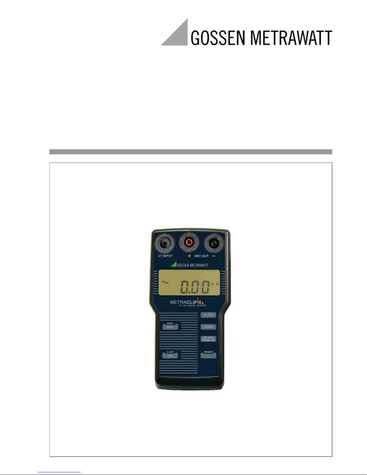
METRACLIP⏐63 / 64
Milliampere Current Clamp
for Measuring Fault, Leakage and Stray Current
3-349-488-03
1/10.08
Page 2
2 GMC-I Messtechnik GmbH
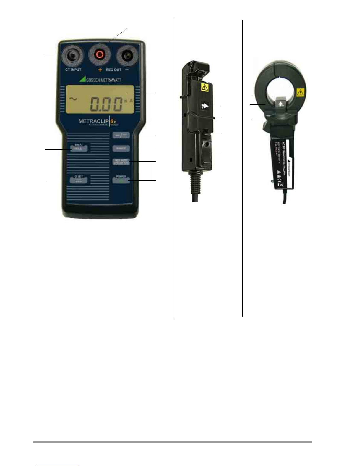
1 CT INPUT: Current clamp connector socket
2 REC OUT: Connector sockets for data logger
3 LCD panel
4 AC / DC: Selector key for direct or
alternating current
5 Range: Measuring range selector key
6
NOT AUTO
POWER OFF
: Key for deactivating auto-shutdown
7 POWER: On/off key
8 0SET: Zero balancing key
9 DATA HOLD: Key for saving measured values
Scope of Delivery
1 measuring instrument
4 LR6 batteries (AA)
1 current clamp
1 carrying pouch
1 set of operating instructions
1
2
3
4
5
6
7
8
9
Measuring Instrument
1
Current Clamp
METRACLIP 63
Current Clamp
METRACLIP 64
1 Arrow must point in
direction of current
flow
2 Safety collar
3 Locking lever
4 Slider for opening
the clamp
Description in
section 4.1
1 Arrow must point in
direction of current
flow
2 Safety collar
3 Key for opening the
clamp
2
3
4
3
1
2
Page 3
GMC-I Messtechnik GmbH 3
Table of contents
1 Safety Precautions .............................3
1.1 General .......................................................3
1.1.1 Meaning of Symbols on the Instrument ..........4
2 Applications ........................................4
3 Initial Start-Up ....................................4
4 Operation ............................................5
4.1 Using the METRA CLIP 63 Current Clamp .....5
4.2 Direct Current Measurement .........................5
4.3 Alternating Current Measurement .................6
4.4 Measuring Leakage and Stray Current ...........6
4.5 Using a Data Logger .....................................7
5 Characteristic Values ..........................8
6 Maintenance .....................................10
6.1 Housing .....................................................10
7
Repair and Replacement Parts Service,
DKD Calibration Laboratory and Rental
Instrument Service .......................................10
8 Product Support ................................11
1 Safety Precautions
1.1 General
You have selected an instrument which
provides you with high levels of safety.
This instrument fulfills all requirements of
applicable European and national EC
guidelines. We confirm this with the CE
mark. The relevant declaration of conformity
can be obtained from GMC-I Messtechnik
GmbH.
The METRACLIP 63 / 64 current clamp is
manufactured and tested in accordance with
safety regulations
IEC 61010-1/EN 61010-1/VDE 0411-1 and
IEC 61010-2-032/EN 61010-2-032/
VDE 0411-2-032
. When used for its
intended purpose, safety of the operator, as
well as that of the instrument, is assured.
Their safety is however not guaranteed, if the
instrument is used improperly or handled
carelessly.
In order to maintain flawless technical safety
conditions, and to assure safe use, it is imperative
that you read the operating instructions
thoroughly and carefully before placing your
instrument into service, and that you follow all
instructions contained therein.
Observe the following safety precautions:
• Avoid excessive mechanical stress such
as impact and vibration, as well as high
temperatures and humidity, because this
may result in damage to the instrument.
• Do not use this instrument in close
proximity to acids, alkaline salts, organic
solutions, corrosive gases etc.
• Do not use this instrument in proximity to
devices which generate strong magnetic
and/or electrical fields, because this may
result in malfunctioning.
• Do not use this instrument in operating
environments where dust or splash
water occur.
Attention!
!
Do not perform measurements at
cables with voltages of greater
than 600 V AC.
Before using the instrument, test the
voltage of the electrical circuit to be
measured.
Do not perform measurements on bare
wires!
Do not subject the input and output
sockets to voltages of greater than
10 V AC.
The current clamp may not be used:
• If the device, the housing or the cable is
damaged
• If the battery compartment lid has been
removed
• For current values which are
impermissible high for the current clamp
• In the rain, with wet hands, in the
presence of splashing water or in moist
environments
Page 4
4 GMC-I Messtechnik GmbH
1.1.1 Meaning of Symbols on the
Instrument
Meaning of Symbols on the Instrument
Warning concerning a source of
danger (attention: observe
documentation)
EC label of conformity
This device may not be disposed of
with the trash. Further information
regarding the WEEE mark can be
accessed on the Internet at
www.gossenmetrawatt.com by
entering the search term WEEE.
CA
TII/III
Measuring category
II
or
III
device
Closing the clamp around
dangerously active conductors is
permissible.
2 Applications
The instrument is capable of measuring
direct and alternating current, and is
equipped with a connectable current clamp.
In the case of direct current measurement,
conventional current clamps are not capable
of performing accurate measurement in the
light current range due to influences resulting
from magnetization and geomagnetism. This
device is a current clamp measuring
instrument which is capable of very accurate
measurement of direct and alternating
current thanks to the use of highly sensitive
materials and a magnetization method.
Attention!
!
The specified maximum input
quantities may not be exceeded in
order to prevent damage to the
instrument and injury to the user:
voltage range: 600 V AC/DC,
current range: 10 A AC/DC.
3 Initial Start-Up
Batteries
Your instrument requires four 1.5 V batteries
(size AA) in accordance with IEC LR6.
Make sure that no battery leakage has
occurred before initial start-up, as well as
after long periods of storage. Continue to
inspect the batteries for leakage at short,
regular intervals.
If battery leakage has occurred, carefully and
completely clean the electrolyte from the
instrument with a damp cloth, and replace
the batteries before using the instrument.
If the “B” symbol appears at the LCD panel,
the batteries should be replaced as soon as
possible.
Battery Replacement
Attention!
!
Disconnect the current clamp from
the measuring circuit before opening
the device in order to replace the
batteries!
Remove the screw from the battery
compartment lid with a screwdriver. Push
the battery compartment lid in the direction
indicated by the arrow and remove it.
Remove the 4 batteries and replace them.
Return the battery compartment lid to its
original position and tighten the screw.
Do not use battery sets consisting of old and
new batteries, or batteries with different
brand names.
!
Page 5

GMC-I Messtechnik GmbH 5
Automatic Shutdown
After switching the device on, “APO” appears
at the LCD (automatic power off). The device
is switched off automatically after 10
minutes if none of its keys have been
activated during this time.
Disabling Automatic Shutdown
The instrument can be set to continuous
operation.
➭ Press the NOT AUTO POWER OFF key to this
end.
4Operation
Attention!
!
For reasons of safety, use the
instrument on electrical circuits with
less than 500 V only. Be sure to
ascertain the voltage level of the
circuit to be measured before starting
the instrument.
Do not activate the 0SET key with open
current clamp. This may lead to erroneous
measurements.
Do not apply direct currents of more than
1.5 A. This may result in measurement error
and damage to the device.
4.1 Using the METRACLIP 63
Current Clamp
Opening and Closing the Clamp
➭ Press the locking lever down in order to
unlock the device.
➭ Press the slider down in order to open
the clamp.
➭ Press the slider up in order to close the
clamp.
➭ Slowly press the locking lever up in order
to securely lock the clamp.
Note!
Correct measurement is only
possible when the current clamp is
fully closed.
Figure 1: Operation, METRACLIP 63
4.2 Direct Current Measurement
➭ Connect the current clamp to the
CT INPUT socket at the measuring
instrument.
➭ Press the POWER key. At first, the 100 mA
measuring range is
displayed.
➭ Select a suitable measuring range at the
measuring instrument with the Range key.
➭ Position the current clamp in proximity to
the conductor to be measured and fully
close it.
➭ Press the 0SET key in order to execute
zero balancing.
The “0” display may be unsteady due to
geomagnetism or external magnetic fields,
but this condition does not indicate
malfunctioning.
If the measuring range is changed, zero
balancing must be executed again.
➭ Open the current clamp and close it
around the conductor to be measured.
➭ Make sure that the direction of the arrow
on the current clamp corresponds with
the flow direction of the current to be
measured.
Locking
Lever
Slider
Slider
Locking
Lever
Open
Close
Page 6

6 GMC-I Messtechnik GmbH
➭ Fully close the current clamp.
➭ Read the displayed value. In the event of
overloading, “OL” appears at the display.
➭ Complete measurement and remove the
clamp from the conductor.
4.3 Alternating Current Measurement
➭ Connect the current clamp to the
CT INPUT socket at the measuring
instrument.
➭ Press the POWER key. At first, the 100 mA
measuring range is
displayed.
➭ Press the AC / DC key. The 100 mA
range is displayed.
➭ Select a suitable measuring range at the
measuring instrument with the Range key.
➭ Open the current clamp and close it
around the conductor to be measured.
➭ Fully close the current clamp.
➭ Read the displayed value. In the event of
overloading, “OL” appears at the display.
➭ Press the DATA HOLD key in order to
freeze the measured value at the display.
“DH” appears at the display.
➭ Press the DATA HOLD key again in order to
return to the measurement.
➭ Complete measurement and remove the
clamp from the conductor.
4.4 Measuring Leakage and
Stray Current
Measuring DC Leakage Current
➭ Measurement is executed in the same
way as for direct current.
➭ However, the clamp is closed around
two conductors simultaneously.
Measuring AC Leakage Current with
Grounded Conductors
➭ Measurement is executed in the same
way as for alternating current.
Measuring AC Leakage Current in Single or
3-Phase Systems, with the Exception of the
Ground Conductor
➭ Proceed in the same way as for the
alternating current measurement,
except that in the case of
single phase systems
2 conductors are simultaneously
enclosed by the current clamp,
and in the case of
3-phase systems
3 conductors are simultaneously
enclosed by the current clamp.
Page 7

GMC-I Messtechnik GmbH 7
4.5 Using a Data Logger
If current measurements will be executed
over a period of hours, the output signal
can be redirected to a data logger (e.g. a
multimeter with memory).
➭ Connect the data logger to the REC OUT
sockets.
➭ Connect the current clamp to the
CT INPUT socket at the measuring
instrument.
➭ Switch the measuring instrument on by
pressing the POWER key.
➭ Press the NOT AUTO POWER OFF key in
order to deactivate automatic
shutdown.
“APO” is cleared from the display.
➭ Switch the data logger on.
➭ Select the appropriate settings for the
desired measurement.
➭ Close the current clamp around the
conductor to be measured.
➭ Select a suitable measuring range (see
output signal under “Device Data” on
page 9) and start recording.
Before changing the measuring range for a
direct current measurement, first remove the
current clamp from the conductor under
test, press the 0SET key and close the
current clamp around the conductor once
again in order to perform a new
measurement.
Please refer to the section entitled “Direct
Current Measurement” for further details.
The output signal for the data logger
corresponds to 100 mV DC full scale for all
ranges.
In the event of overloading amounting to
more than 110% of the selected range, the
output signal generates a display of “0 mV”
in order to draw attention to this situation.
Page 8

8 GMC-I Messtechnik GmbH
5 Characteristic Values
Direct Current (after zero balancing with the 0 SET key)
Key
rdg. = reading (measured value)
d = digit(s)
Reference Conditions
Ambient temperature: +23° C ±5° C
Relative humidity: Max. 85% (no condensation allowed)
Influencing Quantities
Geomagnetism influence: Less than ±0.5 mA
Magnetization influence: Less than ±0.5 mA at 1.5 A DC on/off
Influence caused by open/
closed current clip: Less than ±0.7 mA
Maximum input current: 1.5 A DC (if current greater than 1.5 A DC is applied,
current clamp output is reduced and “OL” does not appear
at the display.
Alternating Current
Maximum input current:20 AAC
METRACLIP 63
Range Measuring Range Resolution Accuracy
100 mA 0.1 ...±50.00 mA 0.01 mA ±1% rdg. ± 5 d
±50.01 ...±99.99 mA ±1% rdg. ±10 d
1000 mA 1 ... ±300 mA 0.1 mA ±1% rdg. ±10 d
±300 ... ±700 mA ±2% rdg. ±10 d
±700 ...±999.9 mA ±3% rdg. ±10 d
METRACLIP 64
Range Measuring Range Resolution Accuracy
100 mA 0.1 ...±99.99 mA 0.01 mA ±1% rdg. ±10 d
1000 mA 1 ... ±300 mA 0.1 mA ±1% rdg. ±10 d
±300 ... ±700 mA ±2% rdg. ±10 d
±700 ...±999.9 mA ±3% rdg. ±10 d
Range Measuring Range Resolution Accuracy
100 mA 0 ... 99.99 mA 0.01 mA ±1% rdg. ±10 d (50/60 Hz)
1000 mA 0 ... 999.9 mA 0.1 mA ±1% rdg. ±10 d (50/60 Hz)
10 A 0 ... 9.999 A 0.001 mA ±1% rdg. ±10 d (50/60 Hz)
Page 9

GMC-I Messtechnik GmbH 9
Device Data
Measuring function: Alternating current / direct current
Measuring method: Current clamp
Measuring ranges: DC: 100 mA / 1000 mA
AC: 100 mA / 1000 mA / 10 A (45 Hz ... 65 Hz)
Detection of alternating current: Average sampling
A-D converter: Dual integration method
Display: LCD, up to 2000 with signal generator
Overload display: “OL” appears at the LCD
“Data Hold” display: “DH” appears at the LCD
Sampling rate: 6 per second for AC and 1 per second for DC
Output signal: 100 mV DC full scale for each range; converted to an
analog signal which becomes zero if it exceeds 110% of
the measuring range in order to indicate overloading
(output impedance: less than 10 kΩ)
Power supply: 4 alkaline batteries (LR6), size AA
Current consumption: Approx. 9 mA (roughly 200 operating hours)
Operating voltage:
Light current range, less than 600 V AC / DC
Operating temperature: 0 ... 50° C, < 85% relative humidity
(no condensation allowed)
Storage temperature: 10 ... 60° C, < 70% relative humidity
(no condensation allowed)
Dielectric strength: 3700 V AC / 1 minute between current clamp core and
handle
Insulation value: 100 MΩ for 500 V DC insulation test between current
clamp core and handle
Safety standard: EC 61010-1/ 61010-2-032,
CAT II 600 V or CAT III 300 V
Dimensions and weight: W x H x D: 78 x 155 x 32 mm, approx. 280 g
Current Clamp Transformer Data for METRACLIP 63
Clamp jaw opening capacity: 5 mm diameter
Dielectric strength: 3700 V AC / 1 minute between metal core and handle
Cable length: 1.2 meters
Safety standard: EC 61010-2-032, CAT || 600 V or CAT ||| 300 V
Dimensions and weight: W x H x D: 19 x 113 x 28 mm, approx. 100 g
Current Clamp Transformer Data for METRACLIP 64
Clamp jaw opening capacity: 30 mm diameter
Dielectric strength: 3700 V AC / 1 minute between metal core and handle
Cable length: 1.2 meters
Safety standard: EC 61010-2-032, CAT || 600 V or CAT ||| 300 V
Dimensions and weight: W x H x D: 33 x 170 x 24 mm, approx. 165 g
Page 10

10 GMC-I Messtechnik GmbH
6 Maintenance
6.1 Housing
No special maintenance is required for the
housing. Keep outside surfaces clean. Use a
slightly dampened cloth for cleaning. Avoid
the use of cleansers, abrasives and solvents.
Return and Environmentally Sound Disposal
The instrument is a category 9 product
(monitoring and control instrument) in
accordance with ElektroG (German electrical
and electronic device law).
This device is not subject to the RoHS
directive.
We identify our electrical and
electronic devices (as of August
2005) in accordance with WEEE
2002/96/EC and ElektroG using the symbol
shown at the right per DIN EN 50419.
These devices may not be disposed of with
the trash. Please contact our repair and
replacement parts service department
regarding the return of old devices.
7
Repair and Replacement
Parts Service,
DKD Calibration Laboratory * and
Rental Instrument Service
If required please contact:
GMC-I Service GmbH
Service Center
Thomas-Mann-Str. 20
90471 Nürnberg, Germany
Phone: +49 911 8602-0
Fax: +49 911 8602-253
e-mail: service@gossenmetrawatt.com
This address is only valid in Germany. Please
contact our representatives or subsidiaries
for service in other countries.
* Calibration Laboratory for Electrical
Quantities
DKD – K – 19701 accredited per
DIN EN ISO/IEC 17025:2005
Accredited quantities: direct voltage, direct
current value, direct current resistance,
alternating voltage, alternating current value,
AC active power, AC apparent power,
DC power, capacitance, frequency, temperature
Competent Partner
GMC-I Messtechnik GmbH is certified in
accordance with DIN EN ISO 9001:2000.
Our DKD calibration laboratory is accredited
by the Physikalisch Technische Bundesanstalt (German Federal Institute of Physics
and Metrology) and the Deutscher Kalibrierdienst (German Calibration Service) in accordance with DIN EN ISO/IEC 17025 under
registration number DKD–K–19701.
We offer a complete range of expertise in the
field of metrology: from test reports and
proprietary calibration certificates right on up to
DKD calibration certificates.
Our spectrum of offerings is rounded out
with free test equipment management.
Our DKD calibration laboratory is part of our
service department. If errors are discovered
during calibration, our specialized personnel
Page 11

GMC-I Messtechnik GmbH 11
are capable of completing repairs using
original replacement parts.
As a full service calibration laboratory, we
can calibrate instruments from other
manufacturers as well.
8 Product Support
If required please contact:
GMC-I Messtechnik GmbH
Product Support Hotline
Phone +49 911 8602-0
Fax: +49 911 8602 709
E-mail: support@gossenmetrawatt.com
Page 12

Edited in Germany • Subject to change without notice • PDF version available on the Internet
GMC-I Messtechnik GmbH
Südwestpark 15
90449 Nuremberg •
Germany
Phone: +49 911 8602-111
Fax: +49 911 8602-777
e-mail: info@gossenmetrawatt.com
www.gossenmetrawatt.com
 Loading...