

Page 1
Operating Instructions
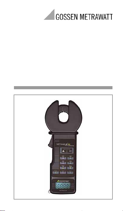
METRACLIP62
Clip-On Ammeter
3-349-391-15
2/3.10
Page 2
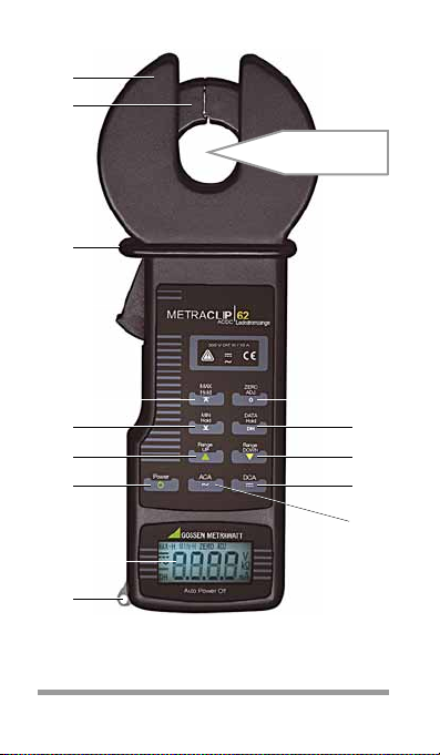
Operating Overview
1
2
15
4
5
6
7
8
9
3
14
13
12
11
10
U: < 300 V !
I: max. 10 A !
2 GMC-I Messtechnik GmbH
Page 3

1 Clip guide (+ shield)
2 Clip jaw
3 Clip clearance safety barrier:
Do not reach beyond the safety collar!
4 Button for opening clip
5
MAX HOLD
key: display max. current measured value
MIN HOLD
6
key: display min. current measured value
7 RANGE UP key: increase measuring range
8 POWER key: switch on instrument (LCD test)
/ switch off instrument
9 LCD panel
10 Eyelet for carrying strap
11 ACA key: activate AC measurement
12 DCA key: activate DC measurement
13 RANGE DOWN key: reduce measuring range
14 DATA HOLD key: save measured value
by „freezing“ display
ZERO ADJ
key:
15
DCA: zero balancing
(activate before each DC measurement
ACA: define reference value
Standard Equipment
1 Clip-on ammeter
1 Immitation leather bag
1 Set of batteries
1 Operating instructions
!)
GMC-I Messtechnik GmbH 3
Page 4

Table of Contents Page
1 Safety Precautions ..............................4
1.1 Special Features of the Hall Effect Sensor ........ 6
2 Operation .............................................7
2.1 Initial Start-Up ...............................................7
2.2 Stipulations for All Measurements ................... 8
2.3 Measuring Leakage Current at Grounded
Conductors .................................................. 10
2.4 Measuring Leakage Current at
Single-Phase or 3-Phase Systems ................ 11
2.5 Measuring Line Current ................................ 12
3 Characteristic Values ......................... 13
4 Maintenance ......................................16
4.1 Battery Replacement .................................... 16
4.2 Housing ...................................................... 17
1 Safety Precautions
The METRACLIP62 clip-on ammeter has been
manufactured and tested in accordance with
safety regulations IEC 61010-1/EN 61010-1/
VDE 0411-1 and IEC 61010-2-032/
EN 61010-2-032/VDE 0411-2-032.
If used for its intended purpose, the safety of
the user and of the device is assured. The
device may only be operated by properly
trained personnel who are capable of recog-
4 GMC-I Messtechnik GmbH
Page 5
nizing the dangers associated with the mea-
!
surement of electrical current and voltage.
Read the operating instructions completely and
carefully before using the device, and follow all
instructions included therein.
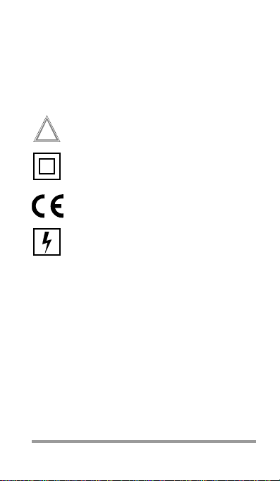
Meanings of symbols on the instrument:
Warning concerning a source of dan
(Attention: observe documentation!)
Continuous, doubled or reinforced
insulation
Indicates EC conformity
Applying the clip to dangerous active
conductors is permitted
The clip-on ammeter may not be used:
• If the battery compartment lid has been
removed
• If visible damage is apparent
• With damaged connector cables
• If it no longer functions flawlessly
• After lengthy periods of storage under
unfavorable conditions (e.g. humidity,
dust, temperature).
ger
GMC-I Messtechnik GmbH 5
Page 6
Attention!
!
Do not perform measurements in the
event of over-ranging!
Current which exceeds the measuring
range may not be measured.
Do not perform measurements at bare
wires!
Do not perform measurements at busbars!
Safe Handling
• The housing and the handles must be free
of dust, grease and moisture.
• The operator’s fingers may not be
extended beyond the safety collar during
measurement.
• Avoid excessive mechanical stress such
as impact and vibration, as well as high
temperatures, moisture and strong
magnetic fields.
•
The battery compartment lid must be
secured with the appropriate Phillips head
screw.
1.1 Special Features of the Hall Effect Sensor
Eliminating the influence of magnetization
The clip-on ammeter METRACLIP62 uses the
hall effect for its measurements. The characteristics of the hall effect are subject to a hys-
6 GMC-I Messtechnik GmbH
Page 7

teresis due to magnetization. As a result, the
zero adjustment point for DC measurements
may vary. Open and close the clip jaws several
times in a row and press the ZERO ADJ key prior
to each DC measurement in order to elimitate
this effect. When measuring current conducting cables, close and open the clip jaws slowly
and firmly in order to avoid any impact on the
sensitive hall effect sensor.
Remedy in the Event of Exceeding the Measuring
Range
If the maximum measurable current has been
exceeded by a large degree, zero balancing
can no longer be effected due to the saturation of the current clip.
Remedy:
➭ Turn the measuring instrument on with the
POWER key.
➭ Adjust the smallest measuring range with
the RANGE DOWN key (200 mA AC).
➭ Close the clip around a conductor with
10 A AC and reduce the current in the
conductor gradually to 0 A. This eliminates magnetic saturation.
2Operation
2.1 Initial Start-Up
Insert the two batteries (see chapter 4.1, page
16.
GMC-I Messtechnik GmbH 7
Page 8

2.2 Stipulations for All Measurements
Attention!
!
Note
In order to prevent damage to the instrument and the user, the maximum
input quantities may not be exceeded:
Voltage range 300 V AC/DC,
current range 20 A AC/DC.
Exercise caution when opening and closing
the clip jaws around an active conductor.
Save Measured Value Function – DATA HOLD
During the performance of measurements
under conditions which impair easy reading of
display values, the DATA HOLD key can be
activated in order to freeze the momentary
measured value at the display. The DH symbol
appears at the display.
Before starting any new measurements, the
DATA HOLD key must be activated once again in
order to reset the data hold function.
Display of Extreme Value Function – MAX HOLD / MIN HOLD
In order to indicate the highest (MAX HOLD) or
lowest current measured value (MIN HOLD) during a measurement, briefly press the corresponding key before starting the measurement; the symbol MAX-H or MIN-H appears.
During this function, the automatic shutdown
8 GMC-I Messtechnik GmbH
Page 9

mode is deactivated. Press the key again to
cancel this function.
Selecting Current Type – ACA / DCA
The measuring instrument is always set to
direct current when switched on. Press the
ACA or DCA key to change to the other current
type.
Zero Balancing or Reference Value Function
– ZERO ADJUST
Zero Balancing for DC measurements DCA
Even if the clip jaws are not closed around a
conductor, measured values are continuously
displayed when the measuring instrument is
set to DC measurement. It is therefore generally necessary to press the ZERO ADJUST key
after selecting the measuring range and before
starting DC measurements. After pressing the
ZERO ADJ key, the symbol ZERO ADJ is displayed
and 0.0, 0 or 0.00 appears on the LCD.
After changing the measuring range or the
current type, the function must be reactivated.
Reference Value for AC measurements ACA
If the ZERO ADJUST key is pressed during an AC
measurement, the measured value is stored
as a reference value and deducted from future
measurements. After pressing the ZERO ADJ.
key, the symbol ZERO ADJ is displayed and
0.0, 0 or 0.00 appears on the LCD.
GMC-I Messtechnik GmbH 9
Page 10

2.3
Measuring Leakage Current at Grounded Conductors
➭ Turn the measuring instrument on with the
POWER key.
➭ Select the current type via the ACA or DCA
key.
➭ Set the RANGE UP or RANGE DOWN key to the
appropriate range for the current to be
measured.
Otherwise, set the measuring range
switch to the highest of the three ranges in
order to avoid possible over-ranging.
➭ Prior to DC measurements:
Perform zero balancing via the ZERO AD-
JUST key.
➭ Close the clip around the current conduct-
ing cable under test as well as around the
current transformer.
➭ Read the measured value from the dis-
play.
➭ After measurement has been completed:
Remove the clip from the cable and turn
the measuring instrument off by pressing
the POWER key.
10 GMC-I Messtechnik GmbH
Page 11

2.4 Measuring Leakage Current at Single-Phase or 3-Phase Systems
➭ Turn the measuring instrument on with the
POWER key.
➭ Select the current type via the ACA or DCA
key.
➭ Set the RANGE UP or RANGE DOWN key to the
appropriate range for the current to be
measured.
Otherwise, set the measuring range
switch to the highest of the three ranges in
order to avoid possible over-ranging.
➭ Prior to DC measurements:
Perform zero balancing via the ZERO AD-
JUST key.
➭ 1-Phase System:
Close the clip around both conducting cables.
3-Phase System:
Close the clip around all 3 conducting cables.
➭ Read the measured value from the dis-
play.
➭ After measurement has been completed:
Remove the clip from the cable and turn
the measuring instrument off by pressing
the POWER key.
GMC-I Messtechnik GmbH 11
Page 12

2.5 Measuring Line Current
➭ Turn the measuring instrument on with the
POWER key.
➭ Select the current type via the ACA or DCA
key.
➭ Set the RANGE UP or RANGE DOWN key to the
appropriate range for the current to be
measured.
Otherwise, set the measuring range
switch to the highest of the three ranges in
order to avoid possible over-ranging.
➭ Prior to DC measurements:
Perform zero balancing via the ZERO AD-
JUST key.
➭ Close the clip around a single current con-
ducting cable only.
➭ Read the measured value from the dis-
play.
➭ After measurement has been completed:
Remove the clip from the cable and turn
the measuring instrument off by pressing
the POWER key.
12 GMC-I Messtechnik GmbH
Page 13

3 Characteristic Values
Measuring sensor Hall Effect
Measuring Ranges
Meas.
Range
Input
A AC TRMS with automatic zero balancing
200 mA 0 199.9 mA 100 A 1.0 % rdg. 5 digits
2000 mA 0 1999 mA 1 mA 1.0 % rdg. 5 digits
10 A 0 9.99 A 0.01 A1.0% rdg. 10 digits
A DC with automatic zero balancing
200 mA 0 199.9 mA 100 A 1.0 % rdg. 3 digits
2000 mA 0 1999 mA 1 mA 1.0 % rdg. 3 digits
10 A 0 9.99 A 0.01 A1.0% rdg. 10 digits
1)
Frequency range: 50 60 Hz, corner frequency 2 kHz
2)
additional error for hall effect due to hysteresis: 3% rdg.
Key:
rdg. = measured value (reading)
Reference Conditions
Ambient temperature +23 C 5 C
Relative humidity max. 80%
Accuracy at 18 ... 28 C,
Reso-
max. 80% relative
lution
humidity
1)
1)
1)
2)
2)
2)
GMC-I Messtechnik GmbH 13
Page 14

LCD
Display
7-segment characters
Number of places 3½ digits,
max. display 1999
Sampling rate Digital display: 1.6/s
Overflow display OL appears
DATA HOLD display DH appears
Power Supply
Batteries 2 ea. LR6 (AA size)
Service life with alkaline manga-
nese batteries:
approx. 120 hours
Battery test Symbol B is dis-
played automati-
cally if battery
voltage is too low.
Automatic shutdown The device turns
itself off automati-
cally 10 minutes
after it has been
switched on.
Electrical Safety
Dielectric strength 2.3 kV AC max.
1 min between the
clip jaws and the
exposed clip hous-
ing
Measuring category 300 V CAT III 10 A
14 GMC-I Messtechnik GmbH
Page 15

Electromagnetic Compatibility (EMC)
Interference emission/
Interference immunity IEC 61326
Ambient Conditions
Operating temperatures 0 C +50 C
< 80% humidity
(no condensation
allowed)
Storage temperatures 20 C +60 C
< 75% humidity
(no condensation
allowed)
(without batteries)
Mechanical Design
Clip opening max. dia. 18 mm
Dimensions W x H x D: 76 mm x
194 mm x 30 mm
Weight
approx. 350 g with
batteries
GMC-I Messtechnik GmbH 15
Page 16

4 Maintenance
Attention!
!
4.1 Battery Replacement
If the battery symbol B appears at the display,
the batteries are either depleted or no longer
supply sufficient operating voltage, and must
be replaced. The batteries should also be
removed if the instrument is placed into storage for a lengthy period of time, because leakage might otherwise occur.
Remove the clip from the measuring
circuit first.
Only then may the battery compartment lid be removed in order to
replace the batteries.
➭ Set the on/off switch (POWER) to the OFF
position.
➭ Remove the screw (size 0) which is used
to secure the battery compartment lid.
➭ Pull the battery compartment lid off in the
direction of the arrow symbol (OPEN).
➭ Carefully pry the batteries out of the com-
partment with the Phillips head screwdriver. Replace the depleted batteries.
Make sure the batteries are inserted with
correct polarity.
16 GMC-I Messtechnik GmbH
Page 17

Note
Always replace both batteries at once.
Note
➭ Slide the battery compartment lid back
into place so that the two pins engage in
the recesses provided.
➭ Reinsert and tighten the screw.
The measuring instrument does not
include any replaceable fuses!
4.2 Housing
No special maintenance is required for the
housing. Keep outside surfaces clean. Use a
slightly dampened cloth for cleaning. Avoid the
use of cleansers, abrasives and solvents.
GMC-I Messtechnik GmbH 17
Page 18

Product Support
When you need support, please contact:
GMC-I Messtechnik GmbH
Product Support Hotline
Phone +49 911 8602-0
Fax +49 911 8602-709
E-Mail support@gossenmetrawatt.com
Repair and Replacement Parts Service
When you need service, please contact:
GMC-I Service GmbH
Service Center
Thomas-Mann-Straße 20
90471 Nürnberg • Germany
Phone +49 911 817718-0
Fax +49 911 817718-253
E-Mail service@gossenmetrawatt.com
This address is only valid in Germany.
Please contact our representatives or subsidiaries for service in other countries.
GMC-I Messtechnik GmbH
Südwestpark 15
90449 Nürnberg • Germany
Phone +49 911 8602-111
Fax +49 911 8602-777
E-Mail info@gossenmetrawatt.com
www.gossenmetrawatt.com
 Loading...