

Page 1
Operating Instructions
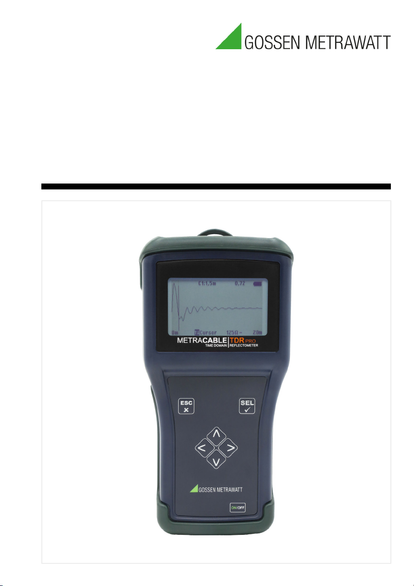
METRACABLE TDR PRO
Time Domain Reflectometer – Cable Fault
and Length Measuring Instrument
3-447-088-03
1/1.21
Page 2

METRACABLE TDR PRO Gossen Metrawatt GmbH
Page 3

Gossen Metrawatt GmbH METRACABLE TDR PRO
Table of Contents
1 Safety Instructions ................................................................................................... 1
2 Applications.............................................................................................................. 2
2.1 Intended Use / Use for Intended Purpose ............................................................. 2
2.2 Use for Other than Intended Purpose.................................................................... 2
2.3 Liability and Guarantee.......................................................................................... 2
2.4 Opening the Instrument / Repairs.......................................................................... 2
3 The Instrument ......................................................................................................... 3
3.1 Scope of Delivery.................................................................................................. 3
3.2 Symbols on the Instrument ................................................................................... 3
3.3 Instrument Overview ............................................................................................. 4
3.4 Technical Data...................................................................................................... 6
3.5 Supported Cable Types ........................................................................................ 7
4 Operation & Settings ................................................................................................ 8
4.1 Power Supply ....................................................................................................... 8
4.2 Switching the Instrument On/Off ........................................................................... 8
4.3 Display (TDR trace) ............................................................................................... 8
4.4 Instrument Menus................................................................................................. 9
4.5 Selecting Instrument Settings.............................................................................. 10
4.6 Changing Measurement Settings ........................................................................ 11
5 Measurements........................................................................................................ 12
5.1 Preparation......................................................................................................... 12
5.2 TDR Measurement.............................................................................................. 13
5.3 Measuring Coaxial Cables................................................................................... 15
5.4 Additional Functions............................................................................................ 15
5.5 Pinpointing and Identifying Faults........................................................................ 16
6 METRACABLE MANAGER..................................................................................... 18
6.1 Downloading & Installation .................................................................................. 18
6.2 Starting and Exiting the Program......................................................................... 18
6.3 Querying Help..................................................................................................... 18
6.4 Accessing Information on the Program and the Manufacturer ............................. 18
6.5 Program Settings................................................................................................ 19
6.6 Connecting the Instrument and METRACABLE MANAGER Software.................. 20
6.7 Synchronizing Instrument and PC Time............................................................... 21
6.8 Cable Database Management............................................................................. 22
6.9 Importing Measurements to the Software............................................................ 24
6.10 Viewing, Evaluating, Exporting, Saving and Printing Measurements..................... 25
6.11 Querying Instrument Information ......................................................................... 27
6.12 Instrument Updates ............................................................................................ 28
Page 4

METRACABLE TDR PRO Gossen Metrawatt GmbH
7 Care and Maintenance........................................................................................... 30
7.1 Battery Replacement .......................................................................................... 30
7.2 Instrument Care.................................................................................................. 31
7.3 Accessories Care................................................................................................ 31
8 Product Support..................................................................................................... 32
9 Repair and Replacement Parts Service /
Calibration Center and Rental Instrument Service ............................................... 32
10 CE Declaration........................................................................................................ 33
11 Return and Disposal............................................................................................... 34
Page 5

Gossen Metrawatt GmbH METRACABLE TDR PRO
1 Safety Instructions
Observe this documentation, in particular all included safety information, in order to protect
yourself and others from injury, and to prevent damage to the instrument.
• Carefully and completely read and adhere to these operating instructions for the instrument.
The respective documents can be found at http://www.gossenmetrawatt.com. Retain
these documents for future reference.
• Use only the recommended accessories with the instrument.
• Tests may only be performed by a qualified electrician, or under the supervision and
direction of a qualified electrician. The user must be instructed by a qualified electrician
concerning performance and evaluation of the tests.
• Wear suitable and appropriate personal protective equipment (PPE) whenever working
with the instrument.
• Always comply with all safety rules and other regulations which are applicable at the place
of use.
• Comply with applicable safety regulations, for example in accordance with
DIN VDE 0100, DIN VDE 0800 and DIN VDE 0805.
• If the instrument doesn’t function flawlessly, remove it from operation and secure it
against inadvertent use.
• The instrument may only be used as long as it’s in good working order.
Inspect the housing before use. Pay particular attention to any possible cracks and the
insulation around the sockets.
• Accessories and cables may only be used as long as they’re fully intact.
Inspect all cables and accessories before use. Pay particular attention to damaged housings, interrupted insulation or kinked cables.
• Do not use the instrument after long periods of storage under unfavorable conditions
(e.g. humidity, dust or extreme temperature).
• Do not use the instrument after extraordinary stressing due to transport.
• Use the instrument only within the specified ambient conditions.
• Use the instrument only in accordance with the specified protection class (IP code).
• The instrument must not be exposed to direct sunlight.
•
The instrument and the included accessories may only be used for the easurements described in this document and the instrument‘s documentation.
• Do not apply any external voltage to the instrument.
• Do not use the instrument if the battery compartment cover has been removed.
Otherwise you risk touching dangerous voltages.
• Hands must be kept behind the probe/terminal guards during testing.
• The operator must check the safety of the circuit before starting the test, and appropriate
precautions must be implemented.
• Circuits must be de-energized and isolated before making any test connections.
• The instrument may only be used with voltage-free cables.
• The instrument is equipped with a Bluetooth
the implemented frequency range of 2.402 to 2.480 GHz is permissible in your country.
• Always create a backup copy of your measurement data.
®
module. Determine whether or not use of
1
Page 6

METRACABLE TDR PRO Gossen Metrawatt GmbH
2 Applications
2.1 Intended Use / Use for Intended Purpose
The METRACABLE TDR PRO is a time domain reflectometer for localizing faults in electrical
cables (e.g. twisted pair, coaxial and power cables), and for measuring their lengths. The
instrument is connected to the voltage-free cable to this end, to which it transmits a pulse.
The pulse’s reflection, i.e. its TDR trace, appears at the instrument’s display panel. The
shape of the trace indicates the length of the cable, any included components, the wiring
itself and even any cable faults.
The METRACABLE TDR PRO can be used in indoor environments, in laboratories, in industrial settings and on construction sites. It’s a portable instrument which can be held in the
hand during measurement, or hung around the neck using the carrying strap. Alternatively,
the METRACABLE TDR PRO can be set up on a suitable surface with the help of the tilt
stand. It can be stored and transported in the included pouch.
The instrument and the cable database can be managed and measurements can be transferred to a PC and viewed with the help of included METRACABLE MANAGER software.
Safety of the operator, as well as that of the instrument, is only assured when it’s used for its
intended purpose.
2.2 Use for Other than Intended Purpose
Using the instrument for any purposes other than those described in these condensed operating instructions, or in the instrument’s operating instructions, is contrary to use for intended
purpose.
2.3 Liability and Guarantee
Gossen Metrawatt GmbH assumes no liability for property damage, personal injury or consequential damage resulting from improper or incorrect use of the product, in particular due
to failure to observe the product documentation. Furthermore, all guarantee claims are rendered null and void in such cases.
Nor does Gossen Metrawatt GmbH accept any liability for data loss.
2.4 Opening the Instrument / Repairs
The instrument may only be opened by authorized, trained personnel in order to ensure flawless, safe operation and to assure that the guarantee isn’t rendered null and void.
Unauthorized modification of the instrument is prohibited.
If it can be ascertained that the instrument has been opened by unauthorized personnel, no
guarantee claims can be honored by the manufacturer with regard to personal safety, measuring accuracy, compliance with applicable safety measures or any consequential damages.
2
Page 7

Gossen Metrawatt GmbH METRACABLE TDR PRO
!
3 The Instrument
3.1 Scope of Delivery
Please check for completeness.
1 METRACABLE TDR PRO (with carrying strap) (M281A)
4 LR6 batteries, 1.5 V, type AA
1 Set of test probes (1.3 m, banana plugs, 300 V Cat II)
2 Alligator clips (plug-on)
1 BNC adapter (banana plug to coaxial cable)
1 Pouch (with carrying strap)
1 Condensed operating instructions
Included “METRACABLE MANAGER” software is available from our website at http://
www.gossenmetrawatt.com. For further information concerning the software please refer to
the following section: “METRACABLE MANAGER
3.2 Symbols on the Instrument
Warning concerning a point of danger
(attention, observe documentation!)
18”.
European conformity marking
The instrument may not be disposed of with household trash.
3
Page 8
METRACABLE TDR PRO Gossen Metrawatt GmbH
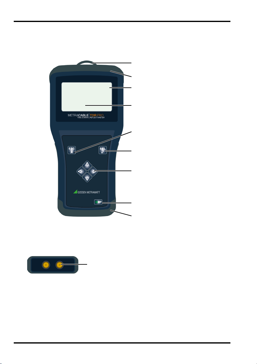
Eyelet for Carrying Strap
Fall Protector
LCD Panel
ESC Key
SEL Key
Scroll keys (for control)
ON/OFF Key
Battery Display
Fall Protector and Battery
Compartment Lid
4 mm Banana Plug Jacks
3.3 Instrument Overview
Front
Top
4
Page 9
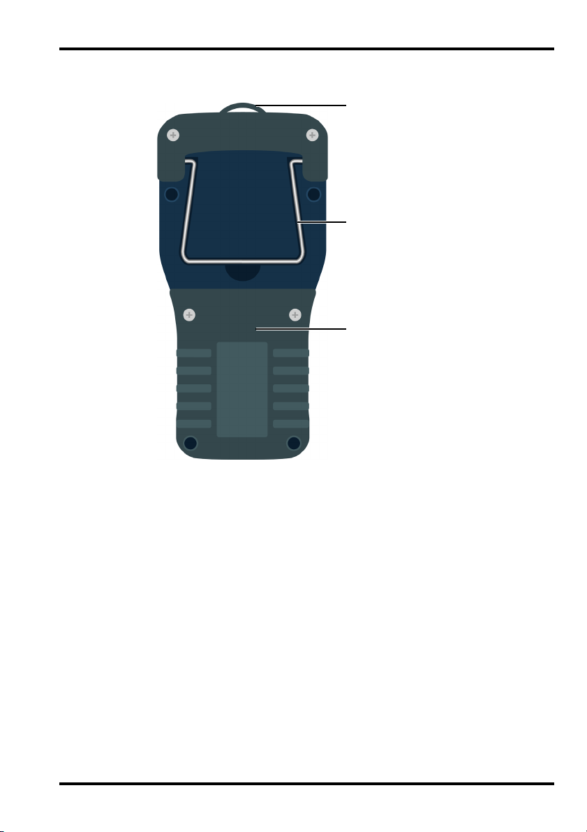
Gossen Metrawatt GmbH METRACABLE TDR PRO
Battery Compartment
Lid and Fall Protector
Tilt Stand
Eyelet for Carrying Strap
Back
5
Page 10
METRACABLE TDR PRO Gossen Metrawatt GmbH
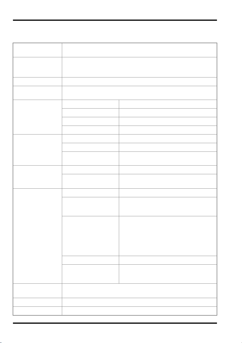
3.4 Technical Data
Power Supply 4 ea. LR6 battery, 1.5 V, type AA or
4 ea. rechargeable NiMH, 1.2 V, type AA
Operating time Up to 30 hours
(depending on battery type and quality),
adjustable automatic shutdown
Connections 2 ea. 4mm banana plug safety jacks
Place of use Indoor environments, laboratories, industrial settings, construction
sites
Ambient
Conditions
Operating temperature: -10 ... +50 °C
Storage temperature: -25 ... +75 °C
Relative humidity: No condensation allowed
Elevation: Max. 2000 m
Electrical
Safety
Pollution degree: 1
Protection category: II per DIN EN 61140/VDE 0140-1
Surge protection DC: 100 V
AC: 230 V / 50 Hz
Electromagnetic
Compatibility (EMC)
Interference emission: EN 55011: 2015
Interference immunity: EN 61000-4-2: 2009
EN 61000-4-3: 2006
Mechanical
Design
Housing (W × H × D): Approx. 19.5 × 10.0 × 4.5 cm
Mechanical protection: Impact-resistant ABS housing with fall pro-
tector and display protection (2 mm Plexiglas with hardened safety glass)
Protection: IP 52
per DIN VDE 0470, part 1/EN 60 529
(protection against ingress of solid foreign
objects: 1.0 mm diameter, protection
against ingress of water: protection
against falling dripping water, when the
housing is inclined up to 15°)
Weight: approx. 390 g (without batteries)
Display: LCD, monochrome, luminous,
240 x 128 pixels, adjustable on-time and
contrast for background illumination
Internal Memory Up to 32 entries in the cable database
Up to 510 measurements in the instrument
Languages German, English, French
Interface Bluetooth
®
6
Page 11
Gossen Metrawatt GmbH METRACABLE TDR PRO
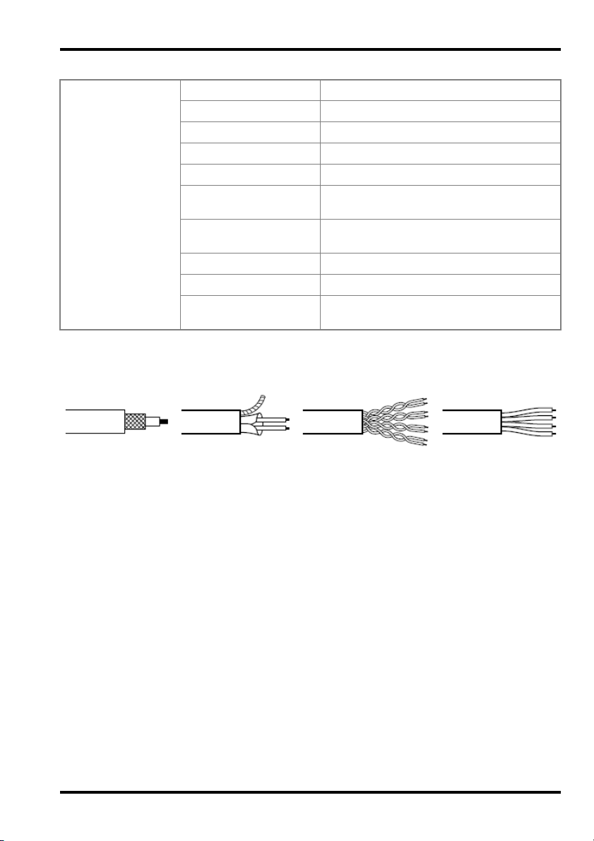
Shielded Cable
Twisted Pair Cable Multi-wire LineCoaxial Cable
Measurements Signal type: Symmetrical search signal
Range: 14 km
Accuracy: +1% ± pixels at 0.66 VF
Resolution: 3.125 ns or 0.3 m (depending on cable)
Output pulse: Max. 20 V pp
Pulse lengths: 12, 25, 50, 100, 200, 500, 1000 and
2500 ns
Velocity factor: Variable from 0.2 to 0.99
in steps of 0.01
Impedance: 50, 75, 100, 125 Ω
Signal type: Symmetrical
Zoom
In steps of 6 dB
(magnification factor):
3.5 Supported Cable Types
Symmetrical cables with maximum attenuation of 80 dB can be measured using the TDR
method. Examples:
7
Page 12
METRACABLE TDR PRO Gossen Metrawatt GmbH
Note!
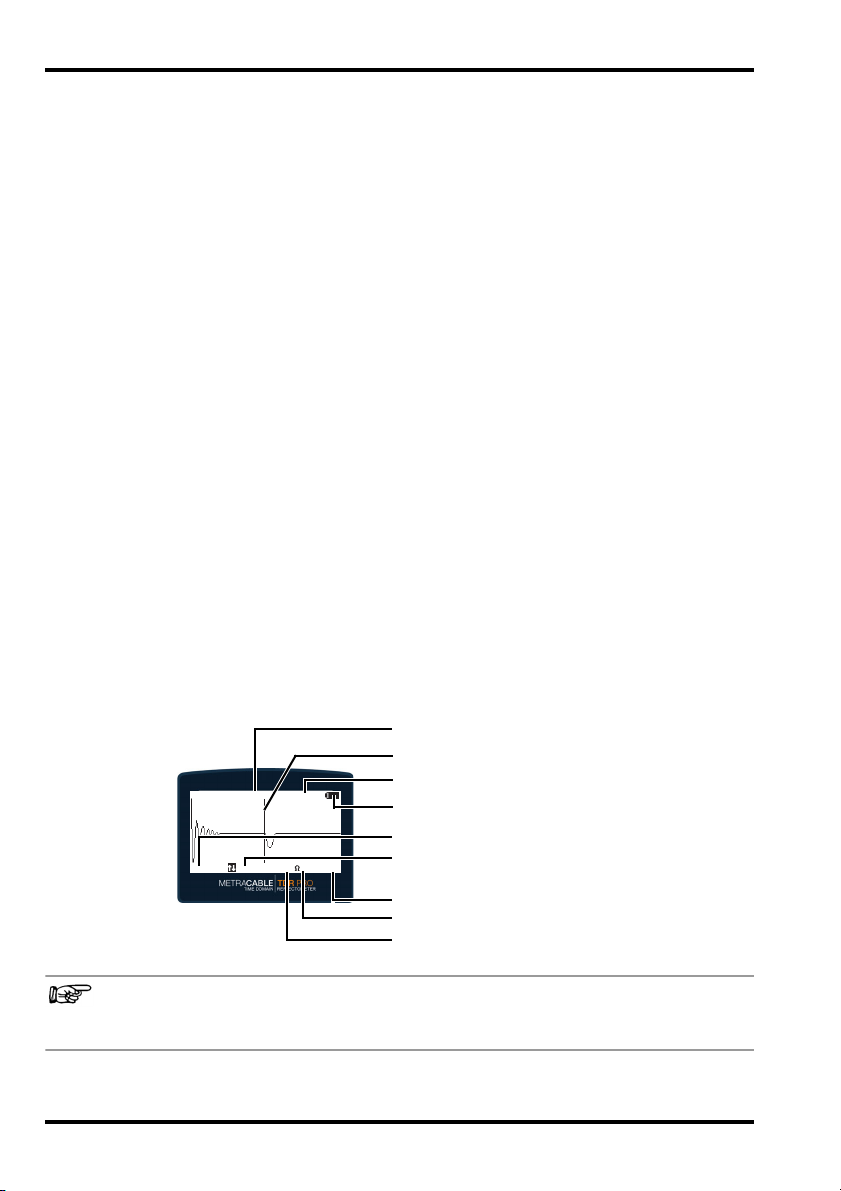
C1:38,7m 0.67
Cursor0m 150 ~ 75m
Absolute Cursor Position
Impedance Display
Cursor
VF Display
Battery Display
Display Range Lower Limit
Function Selected via the
and Scroll Keys
Display Range Upper Limit
Input Display, AC (~) or DC (–)
4 Operation & Settings
This section describes operation of the instrument and the settings which can be selected
for the instrument, as well as for measurements performed with the instrument.
• Power Supply
• Switching the Instrument On/Off
• Display (TDR trace)
• Instrument Menus
• Selecting Instrument Settings
• Changing Measurement Settings
4.1 Power Supply
The instrument is battery-operated. Charged batteries are shipped loose, which you installed
during initial startup
If the batteries are depleted and have to be replaced “Battery Replacement”
4.2 Switching the Instrument On/Off
Press the ON/OFF key in order to switch the instrument on and off. The TDR trace is displayed
immediately after pressing the ON/OFF key.
4.3 Display (TDR trace)
The TDR trace appears in the display as a default function.
The cursor can be moved to the right or the left with the help of the scroll keys. Pressing and
holding the scroll key causes the cursor to move more quickly.
By pressing the SEL key, a function is selected which can then be controlled with the help of
the two scroll keys, namely Cursor, Length, Y-Zoom or X-Zoom. For example if length is
selected, length can be reduced or increased with the help of the scroll keys.
8
8
8
9
10
11
condensed operating instructions (included with the instrument).
30.
Detailed information concerning the use of the TDR trace display “Measurements”
12
8
Page 13

Gossen Metrawatt GmbH METRACABLE TDR PRO
4.4 Instrument Menus
The instrument has two menus: the main menu with basic settings and the TDR menu with
specific settings for measurements.
• Main Menu Overview
•TDR Menu Overview
Main Menu Overview
Press and hold the ESC key in order to open the main menu. Use the scroll keys to navigate
within the menu, and to make selections and entries. Press the SEL key in order to acknowledge a selection. Click TDR Measurement in order to return to the TDR trace.
TDR measurement Exit menu / return to measurement
Velocity factor VF value
Cable type Access to the cable database and selection of the cable type (including
Data transmission Activate Bluetooth for data transmission to the PC (METRACABLE
Settings Language German, English, French
9
10
The material-dependent velocity of propagation of the signal within the
cable is taken into consideration by means of the VF value. It must be
selected individually for each respective cable so that distance can be
calculated correctly.
VF value entries)
(max. 32 entries)
(“METRACABLE MANAGER” 18)
MANAGER
Unit of measure Meters (m) or feet (ft) in combination with velocity
Battery type Battery or rechargeable battery
Illumination Display illumination time after last entry
Shutdown Auto-shutdown of the instrument after last entry
Contrast -20 … +50 (default: 20)
Program update Start the update process
Time Time of day in 24-hour format
Date Date in format DD/MM/YY
18).
factor VF or half of velocity factor VF/2
(depending on which is used
0 … x sec. (0 = continuously on)
0 … x min. (0 = continuously on)
30)
9
Page 14

METRACABLE TDR PRO Gossen Metrawatt GmbH
Note!
TDR Menu Overview
The TDR menu is opened by pressing and holding the SEL key. Use the scroll keys to navigate within the menu, and to make selections and entries. Press the SEL key in order to
acknowledge a selection. Press the ESC key in order to return to the TDR trace.
Reference Saves the momentary measurement as a reference curve in the background
Save Saves the momentary measurement with timestamp.
Freeze Freezes the momentary trace at the display.
Input Selection of either AC or DC.
Pulse
length
Z Impedance of the cable to be measured.
for comparing two measurements.
The reference curve is not changed during Y zooming.
(Data can be transferred subsequently to the PC via Bluetooth “METRA-
CABLE MANAGER”
• AC = capacitive coupling to the cable. Increased protection against interference voltage.
• DC = direct connection to the cable. Less protection against interference
voltage.
Use DC for long cables (long pulse times influence the graphic representation
of the TDR trace when using AC).
Selection of the desired pulse length.
Pulse transmission duration is changed when the TDR range is adjusted. Pulse
length must be increased in order for the instrument to overcome signal attenuation and still be able to determine cable length. However, shorter pulse
lengths result in better resolution.
These values are available from the respective cable manufacturers
(determined automatically when the AUTO Test function is used).
18.)
4.5 Selecting Instrument Settings
The most important settings have already been selected during initial startup condensed operating instructions (included with the instrument). These include the following
basic instrument settings:
• Language
• Units of measure in combination with the velocity factor
• Illumination
•Shutdown
•Contrast
Detailed information concerning the settings and their values “Main Menu Overview”
Instrument settings can be adjusted at any time:
9.
10
Page 15

Gossen Metrawatt GmbH METRACABLE TDR PRO
1. Press the ON/OFF key at the instrument.
The instrument is switched on and the TDR trace is displayed.
2. Open the main menu by pressing and holding the ESC key.
The main menu appears.
3. Navigate to the Settings submenu with the help of the and keys.
4. Acknowledge by pressing the SEL key.
The Settings menu is displayed.
5. Navigate to the desired setting with the help of the and scroll keys.
6. Acknowledge by pressing the SEL key.
The respective submenu is displayed.
7. Select the desired option or enter the desired value.
8. Acknowledge by pressing the SEL key.
The setting is saved.
9. Return to the measurement function by pressing the ESC key.
The instrument is ready to perform measurements.
4.6 Changing Measurement Settings
The following settings are required for measurements:
•AC or DC input
• Pulse length
• Cable impedance
Detailed information concerning the settings and their values “TDR Menu Overview”
These settings should be selected before performing a measurement. However, if necessary
they can also be changed during a measurement. The measurement is restarted automatically after each change.
1. Press the ON/OFF key at the instrument.
The instrument is switched on and the TDR trace is displayed.
2. Open the TDR menu by pressing and holding the SEL key.
The TDR menu appears.
3. Navigate to the desired setting with the help of the and scroll keys.
4. Acknowledge by pressing the SEL key.
The respective submenu is displayed.
5. Select the desired option or enter the desired value.
6. Acknowledge by pressing the SEL key.
The setting is saved.
7. Return to the measurement function by pressing the ESC key.
The measurement is updated automatically based on the changed settings.
10.
11
Page 16

METRACABLE TDR PRO Gossen Metrawatt GmbH
5 Measurements
The METRACABLE TDR PRO is connected to the voltage-free cable to be measured. It performs a TDR measurement (time domain reflectometry) whose results appear at the display
as a TDR trace.
The instrument transmits an electrical pulse during measurement. Cable length can be calculated based on the amount of time it takes for the pulse signal to return to the instrument
(reflection). The shape of the reflection provides information concerning:
• Any included components (e.g. a splitter)
• The wiring itself (e.g. splices, branches etc.)
• Cable faults (short-circuits, broken cable, pinching etc.)
The locations of these items are also calculated – accurate to approximately 0.3 m – based
on the time it takes for the signal to return to the instrument.
Cables with lengths of up to 14 km can be examined with the METRACABLE TDR PRO.
Proceed as follows:
1. Prepare for measurement
2. Perform the measurement.
– TDR Measurement 13
– Measuring Coaxial Cables
3. Optional: Evaluate any detected cable faults
4. Optional: Transfer your measurements to METRACABLE MANAGER PC software for
detailed viewing and evaluation “METRACABLE MANAGER”
12.
15
16.
18.
5.1 Preparation
1. The cable’s velocity factor (VF value) must be known in order to perform measurements.
The material-dependent velocity of propagation of the signal within the cable is taken into
consideration by means of the VF value. It must be selected individually for each respective cable so that distance can be calculated correctly.
The instrument includes a cable database which can accommodate up to 32 entries (all
of which are completed upon shipment). You can select an appropriate cable type from
the database (including velocity factor). The cable database can be maintained in
METRACABLE MANAGER software, e.g. cable types can be edited (
As an alternative, the VF value can be specified manually. You can obtain the VF value
from the cable manufacturer or determine if yourself. Set the unit of measure to half of
the velocity factor V/2 (
cable with a known length and manually adjust the VF value until displayed cable length
coincides with the actual length of the reference cable. This value is the VF value for all
cables of identical design.
2. The METRACABLE TDR PRO includes a number of helpful additional functions. Familiarize yourself with these functions before performing measurements “Additional Functions”
15.
3. Read the instructions concerning pinpointing and identifying faults
12
9) to this end, perform a TDR measurement on an identical
18).
16.
Page 17

Gossen Metrawatt GmbH METRACABLE TDR PRO
Note!
5.2 TDR Measurement
The momentary TDR trace is always shown at the display. If you change a setting, the TDR
trace is adjusted automatically.
The electrical cable to be measured is not in use.
The velocity factor (VF value) of the cable to be measured is known, or there’s a corre-
sponding entry in the cable database (22).
1. Connect the test probes to the METRACABLE TDR PRO.
2. Optional (recommended): Plug the alligator clips on to the test probe.
3. Hold the probes against the cable to be measured or connect the alligator clips to the
cable to be measured. One test probe or alligator clip must directly contact each of the
two conductors (without insulation).
Measuring Coaxial Cables 15
4. Press the ON/OFF key at the instrument.
The instrument is switched on and the TDR trace is displayed.
5. Adjust the velocity factor (VF value) to match the cable under test.
– The instrument includes a cable database with entries for various cable types. Select
an appropriate cable type:
Open the main menu by pressing and holding the ESC key. Navigate to the Cable Type
submenu with the help of the scroll keys and acknowledge your selection by pressing
the SEL key. Select the appropriate entry from the database which then appears with
the help of the scroll keys, and acknowledge your selection by pressing the SEL key.
In order to return to the TDR trace, navigate to the TDR Measurement submenu and
acknowledge your selection by pressing the SEL key.
(Enter the value manually if you don’t find an appropriate entry. See instructions
below.)
– Enter the value manually.
Open the main menu by pressing and holding the ESC key. Navigate to the Velocity
Factor submenu and acknowledge your selection by pressing the SEL key. Enter the
value with the help of the scroll keys and acknowledge by pressing the SEL key. In
order to return to the TDR trace, navigate to the TDR Measurement submenu and
acknowledge your selection by pressing the SEL key.
6. Open the TDR menu by pressing and holding the SEL key.
The TDR menu appears.
7. Enter the basic settings for the momentary measurement: input (AC or DC), pulse length
and impedance (Z) (
Press and hold the SEL key to this end, in order to open the TDR menu. Use the scroll
keys to navigate through the options, and to make selections and entries. Press the SEL
key to acknowledge your selection and entries. Then return to the TDR trace by pressing
the ESC key.
11).
13
Page 18

METRACABLE TDR PRO Gossen Metrawatt GmbH
Note!
Note!
Note!
C1:40.2m 0.67
Cursor0m 150 ~ 300m
Use the AUTO Test function (“Additional Functions” 15)!
Instead of adjusting impedance (Z) manually, it can be determined automatically by the
instrument.
Briefly press the ESC key in order to activate the AUTO Test function.
8. Adjust length (display range) in the TDR trace:
Briefly press the SEL key repeatedly until the Length function is selected. Adjust length
with the help of the and scroll keys.
(Maximum length depends on the cable.)
If length is changed, pulse length is automatically readjusted.
9. Adjust the display range of the TDR trace as required:
Briefly press the SEL key repeatedly until the X Zoom or Y Zoom function is selected. Zoom
in with the scroll key and zoom out with the scroll key.
– Y Zoom: Magnifies/reduces the measuring range display in steps of 6 dB.
– X Zoom: Magnifies/reduces the display of the measurement segment. A cursor which
has been inserted in the display can be used as a zoom reference.
10. Navigate to the desired position within the TDR trace with the help of the cursor:
Briefly press the SEL key repeatedly until the Cursor function is selected. Move the cursor
with the help of the and scroll keys (press and hold a scroll key for rapid motion).
You can display a second cursor to measure two reflection points (e.g. measurement of
distance between distributor and fault or distributor and distributor). Use the scroll key
to switch back and forth between the two cursors and absolute position and difference:
– C1: absolute position of cursor 1, cursor 1 is active
– C2: absolute position of cursor 2, cursor 2 is active
– ΔC1: difference between cursors 1 and 2, cursor 1 is active
– ΔC2: difference between cursors 1 and 2, cursor 2 is active
Distance is calculated on the basis of the velocity factor (VF value 12). If this has
not been entered correctly for the respective cable, distance is displayed incorrectly.
14
Page 19

Gossen Metrawatt GmbH METRACABLE TDR PRO
Attention!
!
11. Optional: determine cable length. Move the cursor to the end of the trace where either
the reflection curve for “open end” or “short-circuit” is displayed (
cursor position corresponds to the length of the cable.
12. Optional: ascertain and analyze any detected reflection curve(s) “Pinpointing and Identifying Faults”
13. Optional: save your measurement.
Open the TDR menu to this end by pressing and holding the SEL key. Navigate with the
and scroll keys until the Save function is selected. Acknowledge by pressing the SEL
key. Enter a name with the help of the and scroll keys. Acknowledge by pressing the
SEL key. The measurement is saved to memory.
14. Switch the METRACABLE TDR PRO off by pressing the ON/OFF key.
The instrument is switched off.
15. Remove all measurement cables from the cable under test and from the instrument.
16. Optional: Transfer the measurements to METRACABLE MANAGER software for further
evaluation and storage “METRACABLE MANAGER”
Measurement has now been completed.
16.
18.
16). The displayed
5.3 Measuring Coaxial Cables
A BNC adapter is included with the instrument for the measurement of coaxial cables.
The BNC adapter may only be used for low-voltage systems.
The coaxial cable to be measured is voltage-free.
1. Connect to the BNC adapter’s banana plugs to the banana jacks on the instrument
4).
(
2. Connect the BNC adapter’s coaxial plug to the coaxial cable to be measured.
3. Perform the measurement “TDR Measurement”
procedure for connecting the test leads.
13. Skip the steps described in the
5.4 Additional Functions
AUTO Test Function
The AUTO Test function determines the impedance of the cable to be measured (up to the
first impedance change, i.e. up to the first reflection which results from, for example, a cable
end or a short-circuit.).
Prerequisite: The cable is longer than 10 meters.
Briefly press the ESC key during measurement in order to use the AUTO Test function
(“Measurements”
Freeze
The freeze function can be used to “freeze” the momentary measurement at the display. This
makes it possible to view and evaluate the TDR trace at leisure.
Proceed as follows in order to freeze the TDR trace during measurement:
12).
15
Page 20

METRACABLE TDR PRO Gossen Metrawatt GmbH
1. Open the TDR menu by pressing and holding the SEL key.
The TDR menu appears.
2. Navigate to the Freeze submenu with the help of the and scroll keys.
3. Acknowledge by pressing the SEL key.
The Freeze menu appears.
4. Select On with the and scroll keys.
5. Acknowledge by pressing the SEL key.
The Freeze menu appears.
6. Return to the measurement function by pressing the ESC key.
The measurement is displayed and is frozen.
Reference Function
Two measurements can be compared at a glance with the help of the reference function.
The first measurement is saved as a reference curve in the background of the second measurement.
Proceed as follows in order to save a TDR trace in the background during a measurement:
1. Perform the first measurement 13.
2. Open the TDR menu during the measurement by pressing and holding the SEL key.
The TDR menu appears.
3. Navigate to the Reference submenu with the help of the and scroll keys.
4. Acknowledge by pressing the SEL key.
The Reference menu appears.
5. Select On with the and scroll keys.
6. Acknowledge by pressing the SEL key.
The Reference menu appears.
7. Return to the measurement function by pressing the ESC key.
The measurement is displayed in the background.
8. Perform the second measurement.
Both measurements are displayed and can be compared with each other.
5.5 Pinpointing and Identifying Faults
Please observe the following notes in the specific case of pinpointing and identifying faults.
Fault Finding Recommendation
When conducting fault finding at a cable, measurement should be performed from both
cable ends – in particular in the case of faults in open circuits in which the actual end of the
cable is not visible.
You can use the reference function in order to compare the two measurements with each
other
When measuring from both ends, the combined results should correspond to the expected
cable length. Even if the actual cable end is indicated at the display, the reflections downstream from the fault may be too uncertain for a conclusive analysis. In this case, measurement from both ends provides a clearer picture with increased accuracy.
16
16.
Page 21

Gossen Metrawatt GmbH METRACABLE TDR PRO
BranchOpen End
Short-Circuit
Splice
Split/Resplit
Water in Cable
Poor Contact Water Ingress
Branch, Short
Splitter
Fault Identification Help
During the TDR method, the instrument transmits a pulse to the cable which is reflected by
cable faults and returned to the instrument. The type of fault can be determined on the basis
of characteristic reflection curves. The instrument also indicates the location of the fault –
accurate down to approximately 0.3 m.
Typical reflection curves and associated cable faults:
17
Page 22

METRACABLE TDR PRO Gossen Metrawatt GmbH
6 METRACABLE MANAGER
Measurement results stored at the instrument can be viewed and evaluated, the internal
cable database can be managed and firmware updates can be installed with the help of
METRACABLE MANAGER PC software.
1. Install the program to your PC 18.
2. Start the program
3. Adjust the program settings to meet your own specific needs
4. Connect the instrument to the program 20.
5. Various tasks can be executed:
– Synchronizing Instrument and PC Time
– Cable Database Management
– Importing Measurements to the Software
– Viewing, Evaluating, Exporting, Saving and Printing Measurements
– Querying Instrument Information
– Instrument Updates
6.1 Downloading & Installation
Installation requirements:
Windows XP
10 MB available hard disk memory
1. Download the latest version from our website:
(The download can be found on the instrument’s individual page.)
2. Unpack the ZIP file.
3. Launch the metracablemanager.exe file.
A Windows wizard guides you through the installation.
The program is installed to the PC.
18.
19.
21
22
24
25
27
28
http://www.gossenmetrawatt.com
6.2 Starting and Exiting the Program
METRACABLE MANAGER is installed on your PC 18.
The program can be launched by means of the usual Windows
using the desktop shortcut.
The program can be closed by clicking Exit in the menu or by clicking the usual × icon.
®
procedures, for example by
6.3 Querying Help
The operating instructions for the instrument and the software (this document) can be
opened in the program by clicking Help in the menu.
The current version of the operating instructions is always displayed.
6.4 Accessing Information on the Program and the Manufacturer
Information concerning the program (e.g. version) and the manufacturer (e.g. contact data)
can be accessed by clicking the arrow next to Help in the menu and selecting the desired
item from the list.
18
Page 23

Gossen Metrawatt GmbH METRACABLE TDR PRO
Note!
6.5 Program Settings
Selecting the Program Language
The program language can be set to either English or German.
1. Select Configuration from the menu.
The Configuration dialog appears.
2. Select the desired language from the Language list in the Basic Settings panel.
3. Acknowledge by clicking OK.
The setting is saved.
Display Options
Whenever a menu item is accessed, the menu is opened in a separate window. You can
specify various display options for this window.
You can activate or deactivate window scaling.
1. Select Configuration from the menu.
The Configuration dialog appears.
2. Activate or deactivate the Dialog Scaling option in the Basic Settings panel.
3. Acknowledge by clicking OK.
The setting is saved.
The arrangement of all currently open windows can be specified with the help of the Windows
menu item.
1. Select Windows from the menu.
The window management drop-down menu appears.
2. Activate or deactivate the Dialog Scaling option in the Basic Settings panel.
3. Acknowledge by clicking OK.
All currently open windows are arranged in accordance with the selected option.
Entering Inspectors
Entries can be made indicating which inspector performed each respective measurement.
When measurements are loaded from the instrument (
24), the specified inspector is
automatically added to the imported measurements. If you generate a report for the measurement (
26), the inspector’s name is added automatically.
If you load a measurement from the PC, the inspector’s name is not overwritten. In
this case either no inspector’s name appears, or the name of the inspector is entered
which was saved to the program with which the measurement was read out from the
instrument. However, you can manually overwrite the inspector’s name when editing
the measurement (26).
1. Select Cable Measurement from the menu.
The Load Measurements dialog appears.
2. Enter the name to the Inspector’s Name field in the Predefined Inspector Data panel.
19
Page 24

METRACABLE TDR PRO Gossen Metrawatt GmbH
Attention!
!
3. Enter additional information concerning the inspector to the Inspector Comment field in the
Predefined Inspector Data panel.
The information is saved.
6.6 Connecting the Instrument and METRACABLE MANAGER Software
A Bluetooth® connection must be established between the instrument and the PC to which
METRACABLE MANAGER has been installed in order to transfer data between the instrument and METRACABLE MANAGER software.
When establishing a connection for the first time, the two devices have to be paired. It must
be assured that the COM port in the operating system and in METRACABLE MANAGER
software match up with each other. After pairing, paired devices link up with each other
automatically when they’re in close proximity to each other and their Bluetooth® modules are
activated.
The corresponding procedure is described below for Windows
for other Microsoft
Your PC is equipped with a Bluetooth
®
Windows® operating systems.
®
port.
METRACABLE MANAGER has been installed to the PC.
1. Open the Windows
®
start menu.
2. Click Settings.
The Windows Settings dialog opens.
3. Click the Devices button.
The Devices dialog appears with the Bluetooth & other devices window.
4. Press the ON/OFF key on the METRACABLE TDR PRO.
The instrument is switched on. The TDR measurement is displayed.
5. Press the ESC key.
The main menu appears.
6. Select Data Transfer from the menu with the help of the scroll keys.
7. Acknowledge by pressing the SEL key.
Bluetooth
®
is activated.
®
10. The procedure is similar
Do not exit this menu item.
If the menu item is exited, the Bluetooth® module is deactivated.
®
8. In Windows
, click the Add Bluetooth or other device button in the Add Bluetooth & other
devices dialog.
The Add a device dialog appears.
9. Click the Bluetooth button.
The system searches for Bluetooth
appear.
20
®
devices. Wait for METRACABLE TDR PRO to
Page 25

Gossen Metrawatt GmbH METRACABLE TDR PRO
Note!
10. Click METRACABLE TDR PRO.
Connection is established.
11. Click Done in the Add a device dialog in Windows
The devices are paired and connected.
12. Open the Windows
®
start menu.
®
.
13. Click Settings.
The Windows Settings dialog opens.
14. Click the Devices button. The Devices dialog appears with the Bluetooth & other devices
window.
15. Click More Bluetooth options in the list on the right.
The Bluetooth Settings dialog is displayed.
16. Click the COM Ports tab.
The COM Ports tab is displayed.
17. Search the list for the port named METRACABLE <serial number> with the Outgoing direction.
Make a note of the port number.
18. Start METRACABLE MANAGER software.
19. Select Configuration from the menu.
The Configuration dialog appears.
20. Check to determine whether or not the previously ascertained COM port appears in the
RS 232 Interface list in the Basic Settings panel. If not, change the entry accordingly.
If the COM port doesn’t appear in the list, click the Rescan COM Ports button. The COM
port list is updated.
21. Acknowledge by pressing the OK key.
The setting is saved.
The devices are paired and connected.
Deactivate the Bluetooth® module in the METRACABLE TDR PRO in order to terminate the
connection. The module can be deactivated by simply exiting the Data Transfer menu item.
6.7 Synchronizing Instrument and PC Time
Measurements are furnished with a timestamp. Instrument time can be set manually 10.
Alternatively, instrument and PC date and time can be synchronized so that the times at
which measurements are performed coincide exactly.
The instrument and the PC/METRACABLE MANAGER are connected to each other.
1. Select Configuration from the menu.
The Configuration dialog appears.
2. Click the Set Time at METRACABLE and PC button in the Update panel.
Time is synchronized.
21
Page 26

METRACABLE TDR PRO Gossen Metrawatt GmbH
Note!
6.8 Cable Database Management
The instrument includes a cable database which is filled with entries for 32 different cable
types at the factory. The appropriate cable entry can be selected for measurements (
thus making it unnecessary to manually enter cable data.
The 32 predetermined cable types represent the maximum possible number of entries. The
cable database can be managed, e.g. edited, in the software. The edited database must
then be transferred back to the instrument.
The entries in the cable database can also be exported in order to back them up and/or
transfer them to other METRACABLE MANAGER installations, and thus to other instruments
as well. Entries are exported and imported as a proprietary copper parameters file with the
extension “.CUP”. Compatible CSV files can also be used.
The cable database is not permanently stored in the program. It has to be loaded from
the instrument or the PC each time it’s needed. After editing, it has to be transferred
back to the instrument and/or saved to the PC. Changes are otherwise lost.
13),
• Loading the Cable Database from the Instrument to the Software
• Manually Adding, Deleting and Editing Cable Parameters
• Exporting the Cable Database from the Software to the PC
• Importing the Cable Database from the PC to the Software
• Uploading the Cable Database from the Software to the Instrument 23
Loading the Cable Database from the Instrument to the Software
Load the cable database from your instrument to the software, after which it can be edited.
The cable database must then be transferred back to the instrument or saved at the PC (see
the following sections).
There’s a cable database in the instrument (included as a default feature).
The instrument and the PC/METRACABLE MANAGER are connected to each other
20.
1. Select Cable Parameters from the menu.
The Cable Parameters dialog appears.
2. Click the Load Cu Parameters from METRACABLE button.
The data are imported to the software from the instrument.
The entries can now be edited.
Manually Adding, Deleting and Editing Cable Parameters
32 cable types are specified in the cable database as a default feature. Existing cable types
can be edited and entries can be deleted in order to add new cable types. entries are
deleted by removing the values from the Cable Name and VF fields.
1. Select Cable Parameters from the menu.
The Cable Parameters dialog appears.
2. Select the field to be edited from the list with a double-click.
The selected entry turns blue.
22
22,
23
23
22
Page 27

Gossen Metrawatt GmbH METRACABLE TDR PRO
3. Enter the new name or value, or delete the field’s content
(cable name: max. 23 characters).
The entry is edited. Repeat this procedure as often as required. After all of your changes
have been completed, transfer the cable database to the instrument.
Sorting Cable Types
Database entries can be sorted in a given order. Frequently used cable types can be placed
at the top of the list and can thus be selected quickly at the instrument.
A cable database has been loaded to the software
1. Select Cable Parameters from the menu.
The Cable Parameters dialog appears.
2. Select the desired entry from the list
3. Click the
The entries are resorted. Transfer the cable database to the instrument or continue editing.
Exporting the Cable Database from the Software to the PC
You can save the cable database to your PC as a CUP file. The entire cable database is
always exported – individual entries cannot be selected for export.
A cable database has been loaded to the software
1. Select Cable Parameters from the menu.
The Cable Parameters dialog appears.
2. Click the Save Cu Parameters to PC button.
The cable database is exported from the software to the PC.
or button in order to move the entry up or down within the list.
22.
22.
Importing the Cable Database from the PC to the Software
A previously saved cable database can be imported to the software. It can then be edited
and/or transferred to an instrument.
A cable database is available as a CSV or CUP file
1. Select Cable Parameters from the menu.
The Cable Parameters dialog appears.
2. Click the Load Cu Parameters from PC button.
The Copper Parameters File dialog appears.
3. Select the CSV or CUP file.
4. Click the Open button.
The cable database is imported and displayed.
Uploading the Cable Database from the Software to the Instrument
A cable database has been loaded to the software
The instrument and the PC/METRACABLE MANAGER are connected to each other
20.
1. Select Cable Parameters from the menu.
The Cable Parameters dialog appears.
2. Click the Upload Cu Parameters to METRACABLE button.
The cable database is exported from the software to instrument.
23.
22.
23
Page 28

METRACABLE TDR PRO Gossen Metrawatt GmbH
6.9 Importing Measurements to the Software
In order to import the measurements from the instrument to the software, the import settings
must first be selected after which data transfer can be started.
If the measurements are available in the form of a file, the file can also be imported to
METRACABLE MANAGER software.
Selecting Import Settings for Import from the Instrument
You can specify whether the data are:
•Only displayed
• Only saved
• Saved and displayed
If the “only saved” or “saved and displayed” option is selected, you also have to specify set-
tings for saving the data:
• The name under which the data will be saved
• Where the data will be saved
• Whether or not the data will be deleted from the instrument after transfer
• Whether or not data on the PC will be overwritten if they have already been transferred in
the past (and perhaps edited)
1. Select Cable Measurement from the menu.
The Load Measurements dialog appears.
2. Select the desired data handling settings, the filename and the memory location in the
Options for Loading from the Instrument panel.
(Information concerning placeholders for filenames can be accessed by clicking the help
button.)
The settings are saved.
Importing Data from the Instrument to the Software
The import settings have already been selected
Measurements have been saved at the instrument
The instrument and the PC/METRACABLE MANAGER are connected to each other
20.
1. Select Cable Measurement from the menu.
The Load Measurements dialog appears.
2. Click the Load Measurement Data from Instrument button.
The data are transmitted.
The measurement data are imported to the software.
You can view, evaluate, save and print the measurement data 25.
Importing Measurement Data from a File
If measurement data are already available as a file, for example from a colleague who performed a measurement with another instrument and stored it to a PC, you can import these
data to the software. The imported data can then be viewed and evaluated. In order to be
able to save the data, a filename must first be specified.
Measurements are available in the TDR file format 26.
24
24.
12.
Page 29

Gossen Metrawatt GmbH METRACABLE TDR PRO
Note!
1. Select Cable Measurement from the menu.
The Load Measurements dialog appears.
2. Specify the file name in the Options for Loading from the PC panel.
(Information concerning placeholders for filenames can be accessed by clicking the help
button.)
3. Connect the PC to the instrument
4. Click the Load Measurement Data from PC button.
The data are transmitted.
The measurement data are imported to the software.
You can view, evaluate, save and print the measurement data
20.
25.
6.10 Viewing, Evaluating, Exporting, Saving and Printing Measurements
If you’ve transferred measurements from the instrument to METRACABLE MANAGER software, reports can be generated and printed. The measurement must be uploaded from the
instrument and displayed to this end 24.
Reports include:
• A logo (selectable)
• Information concerning the measuring instrument (type, serial number)
• Information concerning the measurement (name and time of measurement, measuring
parameters)
• Graphic evaluation of the measurement data
• Information concerning the inspector (name, comment)
• Information concerning the customer (name, comment)
• Signature field
• The filename in the footer (optional)
• A signature field for signing the report (optional)
Proceed as follows:
1. Enter the inspector’s name
2. Select your logo
3. Select a printer and specify printing options 26.
4. Load the measurement data and open them for viewing 24.
5. Generate a report
6. Save and/or print the report 26.
Using Your Own Logo
You can add your own logo to the reports. Logo requirements:
• File format: JGP or BMP
• Dimensions: ideally 280 × 110 pixels (W × H) – other formats are compressed to these
dimensions.
The logo is included as a reference, i.e. it’s not saved in the program and must always
be available at the specified memory location.
25 (optional).
26.
19 (optional).
25
Page 30

METRACABLE TDR PRO Gossen Metrawatt GmbH
Your logo has been saved to the PC.
1. Select Cable Measurement from the menu.
The Load Measurements dialog appears.
2. Click the Settings button in the Print Options panel.
The print options dialog appears.
3. Select your logo file in the Logo Image for Report Header in the Print Options field.
4. Acknowledge by clicking OK.
The selected logo is then printed in all reports.
Selecting Print Options
Before printing reports, a printer must be selected and options must be specified with regard
to format, the footer and the signature field.
A printer has been connected and installed to your PC.
1. Select Cable Measurement from the menu.
The Load Measurements dialog appears.
2. Click the Settings button in the Print Options panel.
The print options dialog appears.
3. Select either the Portrait or Landscape format.
4. Activate or deactivate the Footer (filename) option.
5. Activate or deactivate the Signature option.
6. Select which printer will be used from the Printer list.
7. Acknowledge by clicking OK.
The print settings are saved.
Viewing, Evaluating, Saving and Exporting Measurements and Generating Reports
1. Import the measurement data to the software.
If the data are imported directly from the instrument, several measurements are displayed. Select the window with the desired measurement.
If the data are imported as a file from the PC, only one measurement is displayed
24.
2. Specify the desired excerpt from the TDR trace:
– : Excerpt from the TDR trace. Select the desired excerpt by clicking into the TDR
trace and marking the desired range with the mouse pointer while pressing and
holding the left mouse key.
– : Entire TDR trace.
3. Insert 1 or 2 cursors into the TDR trace in order to display the absolute position of the
event and/or to measure the distance between two events (optional). Click to this
end and then click into the TDR trace with the left mouse key in order to insert the blue
cursor, and with the right mouse key in order to insert the red cursor. If only one cursor is
inserted into the trace, it’s absolute position is displayed. If a second cursor is inserted,
distance between the two cursors is additionally displayed.
4. Optional: Enter the customer’s name or company to the Customer field, for whom the
measurement has been performed.
5. Optional: Enter additional information concerning the customer to the Comment field.
26
Page 31

Gossen Metrawatt GmbH METRACABLE TDR PRO
6. If an inspector has been entered (19), his name appears in the report. The name of
the inspector can be changed as an option. Enter another name to the Inspector field to
this end.
7. If a comment concerning the inspector has been entered (
19), the comment appears
in the report. The comment can be changed as an option. Enter other information to the
Comment field to this end.
8. Optional: Save the edited measurement.
– Click the Save button in order to save the measurement to the program folder.
– Click the Save As button in order to save the measurement to any desired memory
location. Enter a new memory location and filename. Acknowledge by clicking Save.
(The memory location and filename are displayed above the buttons in the Filename
panel.)
The measurement is saved to memory.
9. Optional: Export the edited measurement as a CSV file. Click the Export button to this
end. The Export Measurement Data as CSV dialog appears. Enter a new memory location and filename. Acknowledge by clicking Save.
The measurement is exported.
10. Optional: Print the edited measurement as a report. Click the Print button to this end.
Before printing, you can display a report preview by clicking the Preview button.
The report is printed.
11. Close the measurement view by clicking the Exit button.
6.11 Querying Instrument Information
You can query information concerning a connected instrument with the help of METRACABLE MANAGER software, for example its hardware version and serial number. This information is necessary if you should need to contact our product support department 32.
The instrument and the PC/METRACABLE MANAGER are connected to each other
20.
1. Select Configuration from the menu.
The Configuration dialog appears.
2. Click the Download Instrument Information button.
Instrument information is displayed at the left-hand side of the Update panel. Make a note
of this information for your support query.
27
Page 32

METRACABLE TDR PRO Gossen Metrawatt GmbH
6.12 Instrument Updates
Firmware and FPGA updates are made available for the instrument.
Firmware Update
In order to update the instrument’s firmware, the new firmware must first be downloaded
and transferred to the instrument. Updating is then started at the instrument.
The instrument and the PC/METRACABLE MANAGER are connected to each other
20.
1. Select Configuration from the menu.
The Configuration dialog appears.
2. View the Firmware Version in the Update panel and make a note of it.
3. Determine the newest firmware version by visiting the Gossen Metrawatt GmbH website
at:
http://www.gossenmetrawatt.com
4. Compare the two versions.
– If they’re identical, the instrument is up-to-date and no action is required.
– If the firmware on the website is newer, download it and proceed as follows.
5. Click the Update Firmware button in the Configuration dialog in the Update panel in the
METRACABLE MANAGER program.
The Select Update File dialog appears.
6. Select the downloaded firmware file.
The file is transferred to the instrument.
7. Exit the Data Transfer menu item at the instrument.
The Bluetooth
8. Select Settings from the menu with the help of the scroll keys.
9. Acknowledge by pressing the SEL key.
The Settings menu is displayed.
10. Select Program Update from the menu with the help of the scroll keys.
11. Acknowledge by pressing the SEL key.
The update is executed. Update Active appears at the display during the update process.
A message indicating successful completion then appears.
The instrument’s firmware has been updated.
®
module is deactivated. The main menu appears.
FPGA Update
In order to update the instrument’s FPGA, the new FPGA must first be downloaded and
transferred to the instrument. Updating is then started at the instrument.
The instrument and the PC/METRACABLE MANAGER are connected to each other
20.
1. Select Configuration from the menu.
The Configuration dialog appears.
2. View the FPGA Version in the Update panel and make a note of it.
3. Determine the newest FPGA version by visiting the Gossen Metrawatt GmbH website at:
http://www.gossenmetrawatt.com
28
Page 33

Gossen Metrawatt GmbH METRACABLE TDR PRO
4. Compare the two versions.
– If they’re identical, the instrument is up-to-date and no action is required.
– If the FPGA on the website is newer, download it and proceed as follows.
5. Click the Update FPGA button in the Configuration dialog in the Update panel in the METRACABLE MANAGER program.
The Select FPGA Update File dialog appears.
6. Select the downloaded FPGA file.
The file is transferred to the instrument.
7. Exit the Data Transfer menu item at the instrument.
The Bluetooth
®
module is deactivated. The main menu appears.
8. Select Settings from the menu with the help of the scroll keys.
9. Acknowledge by pressing the SEL key.
The Settings menu is displayed.
10. Select Program Update from the menu with the help of the scroll keys.
11. Acknowledge by pressing the SEL key.
The update is executed. Update Active appears at the display during the update process.
A message indicating successful completion then appears.
The instrument’s FPGA has been updated.
29
Page 34

METRACABLE TDR PRO Gossen Metrawatt GmbH
Attention!
!
Attention!
!
7 Care and Maintenance
With the exception of the batteries which need to be replaced or recharged from time to
time, the METRACABLE TDR PRO does not include any components which require maintenance by the user. Battery replacement and care of the instrument and its accessories are
described below.
7.1 Battery Replacement
Batteries are included with the instrument, which you installed during initial startup condensed operating instructions (included with the instrument). If the batteries are depleted
they have to be replaced. Either conventional or rechargeable batteries can be used, as long
as they’re comparable with those specified in the technical data (
Risk of injury due to contact with dangerous voltages.
Only use the instrument when the battery compartment lid is inserted and firmly
screwed into place.
After replacing the batteries with new conventional or rechargeable batteries, the instrument
has to be set for use with either conventional or rechargeable batteries.
Required tools: Philips screwdriver
Required replacement parts: 4 conventional or rechargeable batteries (which are compara-
ble with the originally included batteries
6)
6).
The instrument is switched off.
All measurement cables and accessories have been removed from the instrument.
1. Place the instrument face down on a stable surface.
2. Loosen and remove the 2 screws from the battery compartment lid.
3. Remove the battery compartment lid by pulling it down.
4. Insert 4 conventional or rechargeable batteries into the battery compartment, making
sure that the plus and minus poles match up with the provided polarity symbols.
Utilized conventional or rechargeable batteries must be comparable with those specified in the technical data (
Use either 4 conventional or 4 rechargeable batteries – do not mix the two types.
5. Slide the battery compartment lid onto the battery compartment.
6. Secure the battery compartment lid with the screws.
7. Press the ON/OFF key at the instrument.
The instrument is switched on and the TDR trace is displayed.
8. Open the main menu by pressing and holding the ESC key.
The main menu appears.
9. Navigate to the Settings submenu with the help of the and scroll keys.
30
6).
Page 35

Gossen Metrawatt GmbH METRACABLE TDR PRO
Attention!
!
Attention!
!
Attention!
!
Attention!
!
10. Acknowledge by pressing the SEL key.
The Settings menu is displayed.
11. Navigate to the Battery Type setting with the help of the and scroll keys.
12. Acknowledge by pressing the SEL key.
The Battery Type submenu appears.
13. Depending on whether you’ve inserted conventional or rechargeable battery, select the
appropriate setting.
14. Acknowledge by pressing the SEL key.
The setting is saved.
15. Return to the measurement function by pressing the ESC key.
The instrument is ready to perform measurements.
7.2 Instrument Care
No special maintenance is required for the instrument. Keep outside surfaces clean. Use a
cloth for cleaning, which has been slightly dampened with water.
Avoid the use of cleansers, abrasives or solvents!
7.3 Accessories Care
No special maintenance is required for the accessories. Keep outside surfaces clean. Use a
slightly dampened cloth to clean the measurement cables.
Avoid the use of cleansers, abrasives or solvents!
Never touch or clean the conductive ends of the test probes!
Inspect the measurement cables, i.e. all cables, for damage at regular intervals. Pay particular attention to interrupted insulation and kinked cables.
Replace damaged measurement cables immediately.
31
Page 36

METRACABLE TDR PRO Gossen Metrawatt GmbH
8 Product Support
If required please contact:
Gossen Metrawatt GmbH
Product Support Hotline
Phone: +49-911-8602-0
Fax: +49-911-8602-709
e-mail: support@gossenmetrawatt.com
9 Repair and Replacement Parts Service /
Calibration Center and Rental Instrument Service
If required please contact:
GMC-I Service GmbH
Service Center
Beuthener Str. 41
90471 Nürnberg, Germany
Phone: +49-911-817718-0
Fax: +49-911-817718-253
e-mail: service@gossenmetrawatt.com
Web: www.gmci-service.com
This address is only valid in Germany. Please contact our representatives or subsidiaries for
service in other countries.
32
Page 37

Gossen Metrawatt GmbH METRACABLE TDR PRO
10 CE Declaration
The instrument fulfills all requirements of applicable EU directives and national regulations.
We confirm this with the CE mark.
33
Page 38

METRACABLE TDR PRO Gossen Metrawatt GmbH
11 Return and Disposal
This instrument is subject to directive 2012/19/EC on Waste Electrical and Electronic Equipment (WEEE) and its German national equivalent implemented as the Waste Electrical and
Electronic Equipment Act (ElektroG) on the marketing, return and environmentally sound disposal of electrical and electronic equipment. The instrument is a category 9 product (monitoring and control instrument) in accordance with ElektroG (German Waste Electrical and
Electronic Equipment Act).
The symbol at the left indicates that this instrument and its electronic accessories
must be disposed of in accordance with applicable legal regulations, and not
together with household trash. In order to dispose of the instrument, bring it to a
designated collection point or contact our product support department (
This instrument is also subject to directive 2006/66/EC on batteries and accumulators and waste batteries and accumulators and its German national equivalent
implemented as the Battery Act (BattG) on the marketing, return and environmen-
tally sound disposal of batteries and accumulators.
The symbol at the left indicates that batteries and rechargeable batteries must be
disposed of in accordance with applicable legal regulations. Batteries and rechargeable batteries may not be disposed of with household trash. In order to dispose of
the batteries or rechargeable batteries, remove them from the instrument and bring
them to a designated collection point.
Segregated disposal and recycling conserves resources and protects our health
and the environment.
Current and further information is available on our website at
http://www.gossenmetrawatt.com under the search terms “WEEE” and “environmental
protection”.
32).
34
Page 39

Gossen Metrawatt GmbH METRACABLE TDR PRO
35
Page 40

Gossen Metrawatt GmbH METRACABLE TDR PRO
© Gossen Metrawatt GmbH
Edited in Germany • Subject to change, errors excepted • PDF version available on the Internet
All trademarks, registered trademarks, logos, product names and company names are the property of their respective
owners.
Phone: +49 911 8602-111
Gossen Metrawatt GmbH
Südwestpark 15
90449 Nürnberg • Germany
Fax: +49 911 8602-777
e-mail: info@gossenmetrawatt.com
www.gossenmetrawatt.com
 Loading...