

Page 1
Operating Instructions
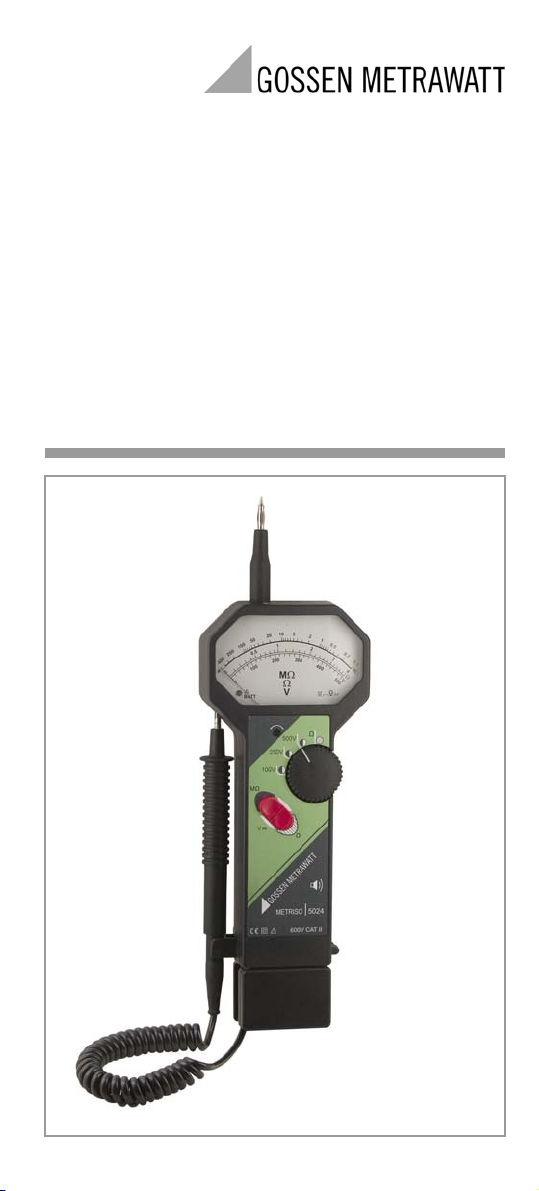
METRISO5024
Insulation and Resistance Measuring Instrument
with Voltage Measuring Range
3-349-346-03
3/3.11
Page 2
1
2
3
4
8
5
7
10
9
6
2a
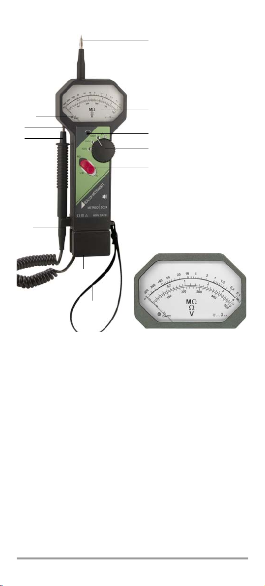
Figure 1 Controls
1 Measuring probe on housing (positive pole)
2Scale
2a Adjusting screw for mechanical zero balancing
3 Rotary switch for
– Ω : Low-resistance measurement (toggle switch in Ω position)
– 100 V/250 V/500 V:
Toggle switch in neutral position:
• Voltage measurement
• Test for absence of voltage and discharge capacitive DUTs
Toggle switch in MΩ position:
• Insulation measurement with the selected test voltage
4 Tog g l e s w i t c h for switching amongst V, Ω and MΩ
(with illuminated scale when Ω or MΩ is selected)
5Carrying strap
6 Battery compartment
7 Detaining fork
8 Test probe on coil cord (negative pole)
9 Opening for securing the test probe
10 LED for indicating device and battery status
(see chapter 4.2 and 4.3)
2 GMC-I Messtechnik GmbH
Page 3

Meanings of symbols on the instrument:
!
Indicates EC conformity
Continuous, doubled or reinforced insulation
Warning concerning a source of danger
(attention: observe documentation!)
CAT I I Maximum allowable voltage between the test probes (1 and 8)
and earth is 600 V, category II.
This device may not be disposed of with the trash. Further
information regarding the WEEE mark can be accessed on
the Internet at www.gossenmetrawatt.com by entering the
search term ’WEEE’.
Table of Contents Page
1 Safety Precautions ...............................................................4
1.1 Defects and Excessive Stressing .......................................................... 4
2 Device Description ................................................................4
2.1 Using Device ......................................................................................4
2.2 Design Description .............................................................................. 4
3 Preparation for Device Operation .........................................5
3.1 Unpacking the Device .........................................................................5
3.2 Power Supply – Battery Replacement ................................................... 5
3.3 Checking the Mechanical Zero Point ....................................................5
3.4 Checking Device Functions .................................................................. 6
4 Operation ..............................................................................7
4.1 Voltage Measurement ......................................................................... 7
4.2
Insulation Resistance Measurement (VDE 0413, part 2 / EN 61557, part 2) ....... 8
4.3
Low-Resistance Measurement (VDE 0413, part 4 / EN 61557, part 4) ............... 9
5 Maintenance – Recalibration ..............................................10
5.1 Housing ........................................................................................... 10
5.2 Batteries ..........................................................................................10
5.2.1 Details on Power Consumption and Operating Time ............................ 10
5.3 Replacing the Fuse ...........................................................................10
5.4 Recalibration .................................................................................... 11
5.5 Device Return and Environmentally Compatible Disposal .....................12
6 Characteristic Values ..........................................................12
7 Repair and Replacement Parts Service
Calibration Center
and Rental Instrument Service ........................................... 14
8 Product Support .................................................................14
GMC-I Messtechnik GmbH 3
Page 4

1 Safety Precautions
The METRISO 5024 insulation measuring instrument is
manufactured and tested in accordance with the following
standards:
IEC 61010-1/EN 61010-1/VDE 0411-1,
IEC 61557-2/EN 61557-2/VDE 0413-2
IEC 61557-4/EN 61557-4/VDE 0413-4
IEC 61326-1/EN 61326-1
IEC 61000-4-2/EN 61000-4-2
IEC 61000-4-3/EN 61000-4-3
IEC 61000-4-4/EN 61000-4-4
IEC 61000-4-5/EN 61000-4-5
IEC 61000-4-6/EN 61000-4-6
IEC 61000-4-8/EN 61000-4-8
In order to maintain flawless technical safety conditions, and to
assure safe use, it is imperative that you read these operating
instructions thoroughly and carefully before placing your instrument
into service, and that you follow all instructions contained herein.
1.1 Defects and Excessive Stressing
If it can be assumed that safe operation is no longer possible, the
instrument must be removed from service and secured against
inadvertent use. It must be assumed that safe operation is no longer
possible:
• If the device demonstrates visible damage
• If the instrument no longer functions
• After long periods of storage under unfavorable conditions
• After extraordinary stressing due to transport
2 Device Description
2.1 Using Device
The METRISO 5024 measuring instrument is a battery operated
combination device with direct display. It is suitable for the following
measurements:
• AC and DC voltages without indication of polarity within a range of
0 to 500 V. This function is especially well suited for testing DUTs
for absence of voltage before performing resistance or insulation
measurements.
• Low resistance measurement within a range of 0 to 4 Ω.
Advantageous for resistance measurements at coils, over
contacts, and at equipotential bonding conductors and
protective conductors.
• Measurement of insulation resistance within a range of 100 kΩ to
400 MΩ. The device is suitable for measuring and testing
insulation resistance at electrical systems and devices and
allows for the selection of the following nominal voltages: 100 V,
250 V or 500 V DC.
2.2 Design Description
Thanks to its design and the use of two-hand operation (Figure 1),
the device is well suited for safe, daily use. It can be secured against
dropping with the attached carrying strap.
The METRISO 5024 includes two switches for device operation:
• Toggle switch for function selection (4)
• Rotary switch (3)
Measured values are displayed at three analog scales (2). Figure 1
shows these scales in detail. Insulation resistance is displayed at the
4 GMC-I Messtechnik GmbH
Page 5

uppermost scale, low-resistance at the middle scale and voltage at
the bottom scale. The device’s operating status and battery charge
level are indicated with the 2-color LED in the scale (Figure 1).
The battery compartment is located in the housing base (6). The
procedure for replacing batteries is described in 3.2.
All measurements are performed with two test probes:
• One test probe (1) is permanently attached to the housing –
positive pole.
• The other (8) is attached to a coil cord – negative pole
This test probe (8) can be inserted into the opening (9) and secured
by snapping the handle into the detaining fork (7).
As long as the toggle switch (4) is in the neutral middle position, the
METRISO 5024 can be utilized as a voltmeter.
The rotary switch must be set either to the 100 V, 250 V or 500 V
position in order to perform voltage measurements. No batteries are
required for this function.
The rotary switch must be set to the Ω position in order to perform
low-resistance measurements. Measurement is performed with the
toggle switch (4) in the Ω position. Voltage cannot be measured as
long as the rotary switch (3) remains in this position.
The desired test voltage must be selected with the rotary switch (3)
before performing insulation measurements. Measurement is
performed with the toggle switch (4) in the MΩ position.
3 Preparation for Device Operation
3.1 Unpacking the Device
Check for mechanical damage after unpacking the device. The
device is ready for use as soon as the batteries have been inserted
into the battery compartment.
3.2 Power Supply – Battery Replacement
The METRISO 5024 is operated exclusively with batteries for safety
reasons. Batteries are inserted or replaced as follows:
Ð First disconnect the measurement cables from the device under
test.
Ð Loosen the fastening screw at the bottom of the battery
compartment (6) and remove the battery compartment.
Ð Remove the depleted batteries and replace them with new or
fully charged batteries. Make sure that battery polarity is not
reversed during insertion (see printed symbols on the
compartment).
Ð Push the battery compartment back in and secure it with the
screw.
Recommended batteries: 4 ea. alkaline batteries per LR6, mignon
cells, AA cells, 1.5 V, at least 2300 mAh
3.3 Checking the Mechanical Zero Point
Ð Lay the device horizontally onto a work surface.
Ð Check the pointer for correct zero point adjustment and reset
with the adjusting screw (2a) if necessary.
The device may not be connected to a measuring circuit during
this procedure, and the toggle switch may not be activated.
Don’t forget: Negative pointer deflection is suppressed by the
scale’s limit stop. Always turn the adjusting screw clockwise for
this reason, and then slowly turn it counterclockwise until the 0 Ω
or 0 V position is reached.
GMC-I Messtechnik GmbH 5
Page 6

3.4 Checking Device Functions
The METRISO 5024 functions as a voltmeter when the toggle switch
(4) is in the neutral position:
Ð The voltmeter function can be checked by applying a voltage to
both test probes (1 and 8), e.g. line voltage from a mains outlet.
The rotary switch must be set to any of positions 100 V, 250 V or
500 V.
Ð When the toggle switch (4) is in either the Ω or MΩ position, the
batteries are activated and the METRISO 5024 remains in the
selected function as long as the toggle switch is activated.
Measurements in the Ω and MΩ ranges are evaluated by means
of the green LED (10), the beeper and the pointer.
Ð The ohmmeter function – ro tary switc h i n the Ω position and toggle
switch in the Ω position – can be tested by short-circuiting the
two test probes (1 and 8): 0 Ω appears at the display,
continuous acoustic signal from the beeper.
Avoid open test probes (resistance approaching ∞), (pointer
oscillates, periodic sequence of acoustic signals from the
beeper).
Ð The insulation measuring function – rotary switch in the xxx V
position and toggle switch in the MΩ position – can be tested
with the help of the two limit values: Short-circuit the two test
probes (1 and 8): Pointer oscillates, periodic sequence of
acoustic signals from the beeper, green LED blinks; separate the
test probes: ∞ appears at the display, continuous acoustic signal
from the beeper, green LED lights up.
Display accuracy can be tested using the ISO Calibrator 1 (article no.
M662A) as an accessory by connecting it to the low or high value
resistor.
6 GMC-I Messtechnik GmbH
Page 7

4Operation
Attention!
!
Ω
500 V
250 V
100 V
Ω
MΩ
V
– (+)
~
+ (–)
~
4.1 Voltage Measurement
Before connecting the measuring instrument to an external
source of voltage, make sure that the battery compartment
has been correctly secured to the housing because the
battery connector terminals are electrically connected to the
measuring circuit!
No auxiliary power is required for voltage measurement, i.e. no
batteries need to be inserted into the battery compartment.
Direct and alternating voltages of up to 500 V can be measured
without switching between zero-frequency and periodic quantities.
Pointer deflection is always positive for the measurement of direct
voltage, regardless of polarity.
Devices under test can be conveniently tested for absence of voltage
using the voltage measuring function without activating any of the
controls. Immediately after connecting the device under test, the
instrument indicates whether or not external voltage is present.
The voltage measuring range can also be used for discharging
capacitive devices under test. The falling voltage value can be
observed at the display.
Adhere to the prescribed sequence for the performance of voltage
measurement:
Ð Set the rotary switch (3) to the xxx V position.
The rotary switch may be set to any position other than Ω!
Ð Leave the toggle switch (4) in its neutral position (do
not press).
Ð Contact the device under test with the test probes
(1 and 8). Read the measured value from the voltage
scale within a range of 0 to 500 V.
Ð End the measurement by removing the test probes from the
device under test.
GMC-I Messtechnik GmbH 7
Page 8

4.2
Attention!
!
Attention!
!
Ω
500 V
250 V
100 V
Ω
MΩ
V
Insulation Resistance Measurement (VDE 0413, part 2 / EN 61557, part 2)
Insulation resistance measurements may only be performed
on voltage-free system components and devices!
Adhere to the prescribed sequence:
Ð Set the rotary switch (3) to the desired test voltage:
100 V, 250 V or 500 V.
Ð Contact the device under test with the test probes
(1: positive pole and 8: negative pole).
Ð When the toggle switch is in the neutral position, the
METRISO 5024 functions as a voltmeter for testing for the absence
of voltage.
Immediately after contacting the device under test, the user can
determine whether or not it is voltage-free.
A capacitively charged device under test is discharged directly
via the voltmeter’s internal resistance. Discharging can be
observed at the display. However, if the voltage value remains
constant insulation resistance cannot be measured until the
device under test has been disconnected from all sources of
voltage.
If zero voltage is displayed, measurement can be performed
immediately.
Ð Insulation resistance measurement is performed for as
long as the toggle switch is held in the MΩ position.
Read the measured value from the logarithmic scale
within a range of 100 kΩ to 400 MΩ.
Ð End the measurement by releasing the toggle switch. Capacitive
devices under test which have been charged by direct test
voltage are discharged by the voltmeter.
Ð Remove the test probes from the device under test.
When insulation resistance is measured at capacitive devices under
test, e.g. cables, they may be charged with an open-circuit voltage
of up to approximately 700 V, and may retain this charge for a
lengthy period of time. This is a life endangering voltage, and the
device under test must be discharged after measurement for this
reason (see “testing for the absence of voltage” above).
Insulation Resistance Scale LED Beeper
Measured value ≥ limit value is displayed green continuous signal
Meas. value < 250 kΩ with UN=250 V
Meas. value < 500 k
Measurement not possible:
– < 100 kΩ
– Battery voltage too low
– Rotary or toggle switch
not adjusted correctly
Ω
with UN=500 V
value is displayed green periodic sequence
pointer oscillates
pointer oscillates
pointer oscillates
green blinks
red
green blinks
of signals
periodic sequence
of signals
no signal
no signal
Evaluating Measured Values
According to DIN VDE 0100, the insulation resistance of system
components must have a value of at least 1000 Ω per V nominal
voltage without any current-consuming apparatus in the line section
between two overcurrent protection devices or switches, or
downstream from the last overcurrent protection device, for example
8 GMC-I Messtechnik GmbH
Page 9
380 kΩ at an operating voltage of 380 V.
Attention!
!
* Minimum display values for
insulation resistances with specified
limit values in consideration of
maximum measuring error.
MΩ Range
Limit value Min. Display *
0.10 MΩ
0.25 MΩ
0.40 MΩ
0.50 MΩ
0.60 MΩ
0.70 MΩ
0.80 MΩ
1 MΩ
2 MΩ
0.130 MΩ
0.325 MΩ
0.520 MΩ
0.650 MΩ
0.780 MΩ
0.910 MΩ
1.040 MΩ
1.300 MΩ
2.600 MΩ
Ω
500 V
250 V
100 V
Ω
MΩ
V
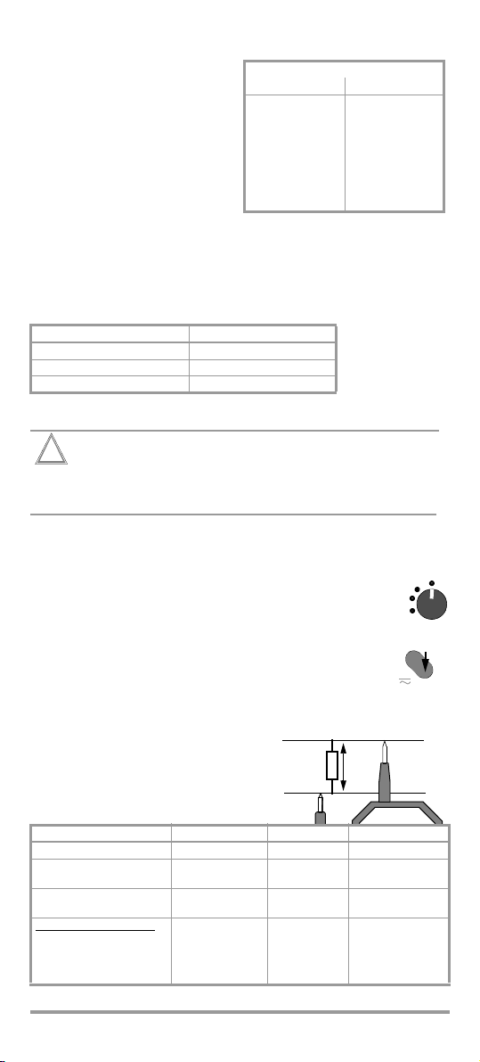
R
x
Voltage Drop
In order to assure that the
insulation resistance limit values
specified in the applicable
standards are not exceeded,
maximum measuring error of the
measuring instrument must be
taken into consideration. The
required minimum display values
for various limit values are listed in
the following table. Intermediate
values can be interpolated in a
linear fashion.
Test Vo ltages
During measurement of insulation resistance, a test voltage U is applied
to the device under test, which lies between the nominal voltage U
selected with the rotary switch (3), and open-circuit voltage U
UN Position at Rotary Switch (3) Test Voltage at DUT
100 V 100 V < U < 110.8 V
250 V 250 V < U < 277.0 V
500 V 500 V < U < 554.0 V
N
:
0
4.3 Low-Resistance Measurement (VDE 0413, part 4 / EN 61557, part 4)
Resistance measurements may only be performed on
voltage-free devices under test, because interference
voltages distort measurement results.
Adhere to the prescribed sequence:
Ð Make sure that the device under test is voltage-free in
accordance with chapter 4.1.
Ð Set the rotary switch to Ω.
Ð Contact the device under test with the test probes (1:
positive pole of the 200 mA constant current source
and 8: negative pole of the constant current source).
Ð Measurement is performed for as long as the toggle
switch is held in the Ω position. Observe the LED.
Read the measured value from the scale within a
range of 0 to 4 Ω. It is advisable to perform a second
measurement with reversed polarity in order to eliminate
semiconductor circuits.
Ð
End the measurement by
releasing the toggle switch.
Ð
Remove the test probes from
the device under test.
Low Voltage Scale LED Beeper
measured value ≤ 2 Ω value is displayed green continuous signal
2 Ω < measured value ≤ 4Ω value is displayed green periodic sequence
measured value ≥ 4Ω pointer oscillates green blinks periodic sequence
measurement not possible:
– battery voltage too low
– rotary or toggle switch
not adjusted correctly
GMC-I Messtechnik GmbH 9
pointer oscillates
pointer oscillates
red
green blinks
of signals
of signals
no signal
no signal
Page 10

5 Maintenance – Recalibration
5.1 Housing
No special maintenance is required for the housing. Keep outside
surfaces clean. Use a slightly dampened cloth for cleaning. Avoid the
use of cleansers, abrasives and solvents.
5.2 Batteries
Check the batteries at short regular intervals to makes sure no
leakage has occurred. If leakage occurs, electrolyte must be fully
removed from the instrument and new batteries must be installed.
Remove the batteries from the battery compartment if the measuring
instrument will not be used for a lengthy period of time. Refer to
chapter 3.2 regarding battery replacement
Attention: If the LED lights up red before or during measurement, the
batteries must be replaced immediately.
Use only recommended battery types (see chapter 3.2).
5.2.1 Details on Power Consumption and Operating Time
Low-Resistance Measurement
The instrument draws the most power from the batteries when the
value of the contact resistance is the lowest.
Power consumption does not exceed the value of 0.4 A.
Insulation Resistance Measurement
Power consumption from the batteries depends on the selected test
voltage and the actual value of the insulation resistance, i.e. on the
load imposed on the source of the measuring voltage U
below specifies the power consumption from the batteries for the
indicated parameters.
Test Voltage
U
N
500 V 0 kΩ / < 1 A * 0.1 MΩ / < 1.1 A > 1 MΩ / < 0.6 A
250 V 0 kΩ / < 1 A * 0.1 MΩ / < 0.4 A
100 V 0 kΩ / < 1 A * 0.1 MΩ / < 0.2 A
(*if LED lights up green, pointer oscillates and there is no acoustic signal,
RX measured at I
the transformer is overloaded)
(U
BAT
> 500 kΩ / < 0.4 A > 400 MΩ / < 0.2 A
> 200 kΩ / < 0.3 A > 400 MΩ / < 0.2 A
BAT
= 6 V)
The following table lists the number of possible measurements with
one set of alcaline batteries by taking into account the power consumption from the batteries.
The number of possible measurements depends on the following conditions:
• one measurement takes 1 minute
• the insulation resistance complies with the requirements of the
standard
(power consumption from the battery in accordance with
column 3 of the table above).
Test Voltage U
N
500 V > 300 measurements
250 V > 500 measurements
100 V > 750 measurements
AlMn Battery min. 2300 mAh
The table
N.
> 400 MΩ / < 0.3 A
5.3 Replacing the Fuse
The low-resistance measuring range is protected with a fuse, see
chapter 6. The fuse blows if a voltage is applied to the test probes
which may cause damage to the instrument as a result of its
magnitude or polarity.
Adhere to the prescribed sequence when replacing the fuse:
Ð Remove the test probes from the device under test.
Ð Loosen the 3 screws in the housing base.
10 GMC-I Messtechnik GmbH
Page 11

Ð Turn the device over so that the control panel faces up and
Note!
Attention!
!
Note!
remove the housing top (i.e. control panel).
Ð Remove the fuse from its holder with the help of an object such
as a test probe, and replace it with a new fuse.
(A replacement fuse is available in the carrying pouch).
Replace the fuse only in a clean and dust-free environment.
Soiling may possibly impair the correct functioning of the
measuring instrument.
Use specified fuses only! If fuses with other blowing
characteristics, other current ratings or other breaking
capacities are used, the operator is placed in danger, and
resistors and other components may be damaged.
The use of repaired fuses or short-circuiting the fuse holder
is prohibited.
Ð Set the housing top back into place without applying pressure.
Ð Lay the carrying strap over the metal pin.
Make sure that the cable from the measuring element is not
pinched when the housing bottom and the housing top are
fitted together.
Ð Position the measuring instrument so that you view it from the
side with the test probe snapped in to the detaining fork. The
support included on the housing top must slide into the guide in
proximity to the test probe holder, and may not be tilted at the
display module. In this way, the housing top can be pressed
onto the housing bottom without applying excessive force.
Ð Hold the housing top and bottom together and turn the entire
instrument over so that the housing bottom faces up.
Ð Retighten the screws.
5.4 Recalibration
The respective measuring task and the stress to which your
measuring instrument is subjected affect the ageing of the
components and may result in deviations from the guaranteed
accuracy.
If high measuring accuracy is required and the instrument is
frequently used in field applications, combined with transport stress
and great temperature fluctuations, we recommend a relatively short
calibration interval of 1 year. If your measuring instrument is mainly
used in the laboratory and indoors without being exposed to any
major climatic or mechanical stress, a calibration interval of 2-3 years
is usually sufficient.
During recalibration
*
in an accredited calibration laboratory
(DIN EN ISO/IEC 17025) the deviations of your instrument in relation
to traceable standards are measured and documented. The
deviations determined in the process are used for correction of the
readings during subsequent application.
*
Verification of specifications or adjustment services are not part of the
calibration. For products from our factory, however, any necessary
adjustment is frequently performed and the observance of the relevant
specification is confirmed.
GMC-I Messtechnik GmbH 11
Page 12

We are pleased to perform DKD or factory calibrations for you in our
Pb Cd Hg
calibration laboratory. Please visit our website at
www.gossenmetrawatt.com (→ Services → DKD Calibration Center
or → FAQs → Calibration questions and answers).
By having your measuring instrument calibrated regularly, you fulfill
the requirements of a quality management system per
DIN EN ISO 9001.
5.5 Device Return and Environmentally Compatible Disposal
The instrument is a category 9 product (monitoring and control
instrument) in accordance with ElektroG (German Electrical and
Electronic Device Law). This device is not subject to the RoHS
directive.
We identify our electrical and electronic devices (as of
August 2005) in accordance with WEEE 2002/96/EG and
ElektroG with the symbol shown to the right per DIN EN
50419.
These devices may not be disposed of with the trash. Please contact
our service department regarding the return of old devices.
If you use batteries or rechargeable batteries in your instrument or
accessories which no longer function properly, they must be duly
disposed of in compliance with the applicable national regulations.
Batteries or rechargeable batteries may contain harmful substances
or heavy metal such as lead (PB), cadmium (CD) or mercury (Hg).
They symbol shown to the right indicates that batteries or
rechargeable batteries may not be disposed of with the
trash, but must be delivered to collection points specially
provided for this purpose.
6 Characteristic Values
Insulation Resistance Measurement, Measuring Voltages: 100 / 250 / 500 V
Measuring Range Intrinsic
0.1 … 400 MΩ 2.5% * 600 V AC > 1 mA < 10 mA
*
Measuring error under reference conditions relative to scale length (l = 84.6 mm)
Uncertainty
Low-Resistance Measurement, Measuring Voltage: 4.5 V
Measuring Range Intrinsic
0 … 4 Ω 2.5% * 250 V DC >200 mA
* Measuring error under reference conditions relative to upper range value (l = 74.9 mm)
Uncertainty
Voltage Measurement, DC / AC (40 … 200 Hz)
Measuring Range Intrinsic
0 … 500 V 2.5% * 600 V AC 450 kΩ
* Measuring error under reference conditions relative to scale length
(l = 73.3 mm)
12 GMC-I Messtechnik GmbH
Uncertainty
Overload Measuring
Overload Measuring Current
Overload Internal Resistance
Current
Short-Circuit
Current
Page 13

Reference Conditions
Normal position of use horizontal
Ambient temperature + 23 °C ± 2K
Relative humidity 40 ... 60%
Measured quantity frequency 45 ... 65 Hz
(during voltage measurement)
Line voltage waveshape sinusoidal (RMS value)
Battery voltage 5.5 V ±0.5 V
Influence Error under Nominal Conditions of Use
Total error caused by battery,
temperature and normal position of use = 10%
Nominal Conditions of Use
Temperature 0 ... 40 °C
Normal position of use any
Battery voltage 4.4 ... 6.5 V
Ambient Conditions
Storage temperature −25 °C ... + 60 °C (without batteries)
Relative humidity max. 75%, no condensation allowed
Elevation to 2000 m
Deployment indoors only, except within specified
ambient conditions
EMC EN 61326
Interference emission EN 55022 class B
Interference immunity EN 61000 -4-2 power feature A
-4-3 power feature B
Power Supply
Batteries 4 ea. 1.5 V mignon-cell per IEC LR6
(4 x size AA)
Working range 4.4 ... 6.5 V
Battery test by means of LED (see chapter 4.2 and 4.3)
Electrical Safety
Safety class II
Test voltage 3.7 kV
Measuring category II / 600 V
Fouling factor 2
Fuse F0.25A/500V, 6.3x32
Mechanical Design
Protection
IP 40 per DIN VDE 0470 part 1/EN 60529
Extract from table on the meaning of IP codes
IP XY
st
(1
Protection against foreign
digit X)
4 ≥ 1.0 mm dia. 0 not protected
object entry
IP XY
(2nd digit Y)
Protection against the
penetration of water
Dimensions 98 mm x 310 mm x 40 mm
Weight approx. 0.5 kg with batteries
GMC-I Messtechnik GmbH 13
Page 14

7 Repair and Replacement Parts Service
Calibration Center *
and Rental Instrument Service
When you need service, please contact:
GMC-I Service GmbH
Service Center
Thomas-Mann-Strasse 20
90471 Nürnberg • Germany
Phone +49 911 817718-0
Fax +49 911 817718-253
E-Mail service@gossenmetrawatt.com
www.gmci-service.com
This address is only valid in Germany.
Please contact our representatives or subsidiaries for service in other
countries.
* Calibration Laboratory
for Electrical Quantities DKD– K – 19701
accredited per DIN EN ISO/IEC 17025:2005
Accredited measured quantities: direct voltage, direct current values, DC
resistance, alternating voltage, alternating current values, AC active power,
AC apparent power, DC power, capacitance, frequency and temperature
8 Product Support
When you need support, please contact:
GMC-I Messtechnik GmbH
Product Support Hotline
Phone +49 911 8602-0
Fax +49 911 8602-709
E-Mail support@gossenmetrawatt.com
Edited in Germany • Subject to change without notice • A pdf version is available on the internet
GMC-I Messtechnik GmbH
Südwestpark 15
90449 Nürnberg •
Germany
Phone +49 911 8602-111
Fax +49 911 8602-777
E-Mail info@gossenmetrawatt.com
www.gossenmetrawatt.com
 Loading...