

Gossen Metrawatt M520P, PROFITEST MBASE, PROFITEST MTECH, PROFITEST MPRO, PROFITEST MXTRA User guide
...Page 1
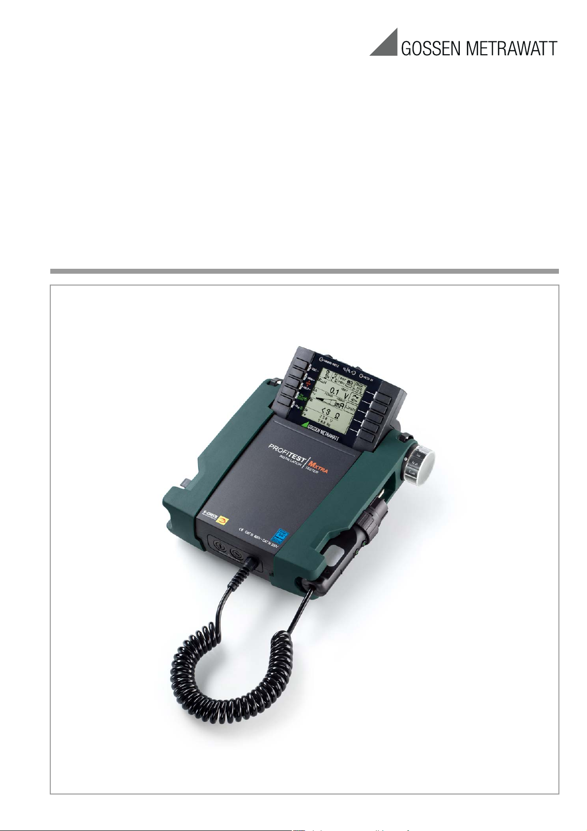
Operating Instructions
Series PROFITEST MASTER
PROFITEST MBASE+, MTECH+, MPRO, MXTRA, SECULIFE IP
Test Instruments for IEC 60364 / DIN VDE 0100
3-349-647-03
15/7.16
Page 2
456
8
91011
7
MEM: Key for memory functions
HELP: Access context sensitive help
IΔ
N
: Tripping test
Proceeding to next function
(semi-automatic measurement)
Start offset measurements
ON/START
: Switch instrument on,
start/stop measurement
ESC:Return to submenu
13
31
Softkeys
Control Panel
Test Instrument and Adapter
16 1715
14
Fixed Function Keys
2
19 20 21
22
12
!
RS 232
2
• Parameter selection
• Specify limit value
• Entry functions
• Memory functions
LEDs and connection icons → section 18
9
10
Sockets for Current Clamp Sensor, Probe and
PRO-AB Leakage Current Adapter
15
16
17
Interfaces, Charger Jack
* Refer to section 2.1 page 5 regarding usage of
the test probes.
*
*
*
18
2 GMC-I Messtechnik GmbH
Page 3
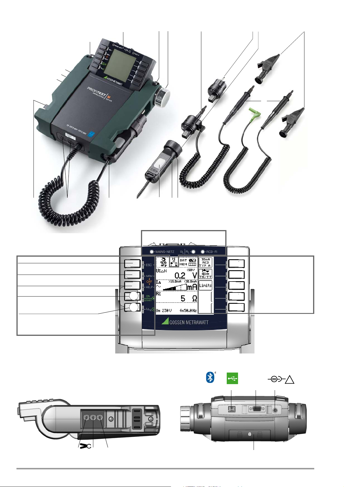
Key
Test Instrument and Adapter
1 Control panel with keys and
display panel with detent for
ideal viewing angle
2 Eyelets for attaching the
shoulder strap
3 Rotary selector switch
4 Measuring adapter (2-pole)
5 Plug insert (country specific)
6 Test plug (with retainer ring)
7 Alligator clip (plug-on)
8 Test probes
9
▼ key ON/START *
10 I key IΔ
N
/compens./Z
OFFSET
11 Contact surfaces for finger
contact
12 Test plug holder
13 Fuses
14 Holder for test probes (8)
Connections for Current Clamp,
Probe and PRO-AB Adapter
15 Current clamp connection 1
16 Current clamp connection 2
17 Probe connection
Interfaces, Charger Jack
18 Bluetooth
®
19 USB slave for PC connection
20 RS 232 for connecting barcode
scanner or RFID reader
21 Jack for Z502P charger
Attention! Make sure that no
batteries are inserted before
connecting the charger.
22 Battery Compartment Lid
(compartment for batteries
and replacement fuses)
Please refer to section 17 for
explanations regarding control
and display elements.
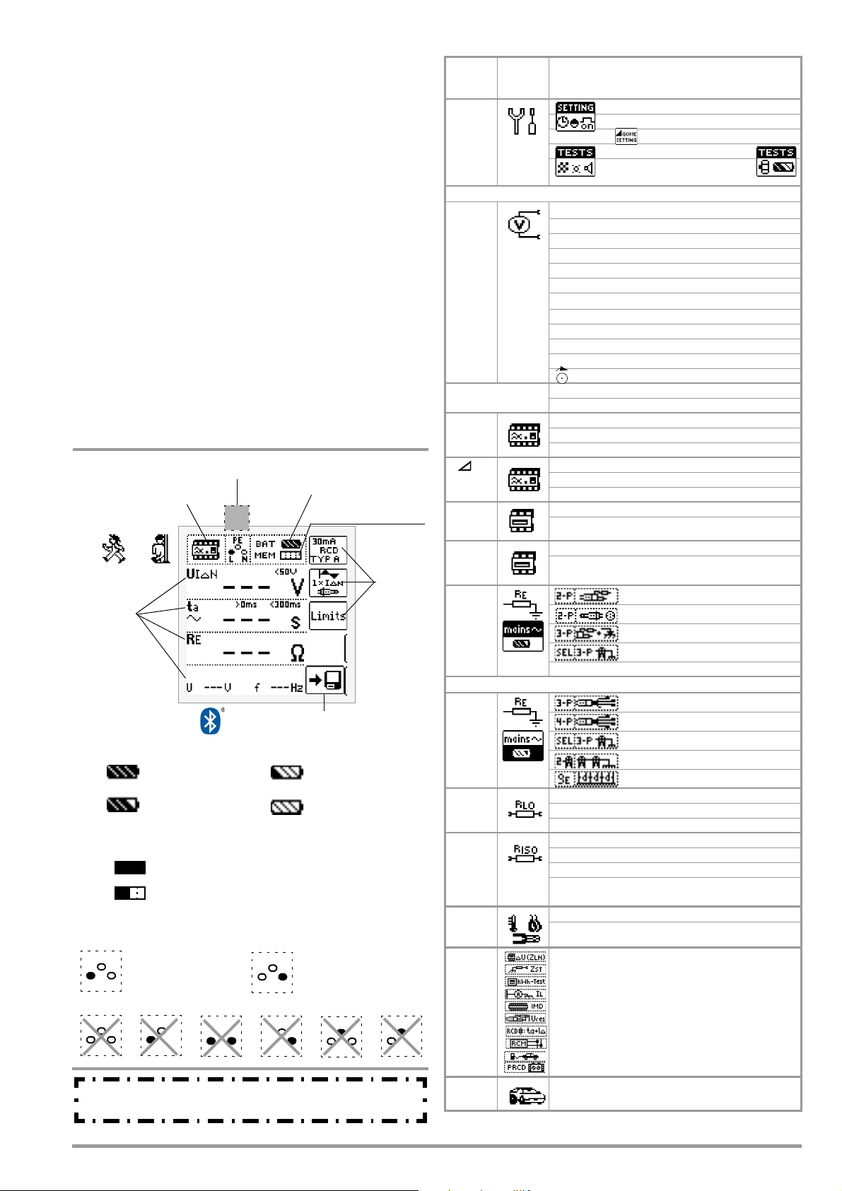
Battery level indicator
Meas. function
Meas. in progress /
Memory occupancy
Measured
Parameter
Display Panel
PE
Save value
Battery full
Battery OK
Battery weak
Battery (nearly)
Battery level indicator
BAT
BAT
BAT
BAT
Memory occupancy display
MEM
Memory half full
MEM
Memory full > transfer data to PC
Connection Test – Mains Connection Test (→ section 18)
NPEL
NPEL
)(
Connection OK L and N reversed
NPEL NPEL
x
NPEL NPEL
x
x
RUN READY
Connection test → section 18
depleted: U < 8 V
LPEN
x
LPEN
These operating instructions describe a tester with
software version SW-VERSION (SW1) 01.16.00
* Can only be switched on with the key on the instrument
Bluetooth® active:
quantities
stopped
Overview of Device Settings and Measuring Functions
Switch
Setting,
Descr. on
SETUP
page 8
Measurements with line voltage
U
page 16
Appears for all meas.
shown below:
IΔN
page 18
IF
page 20
ZL-PE
page 26
ZL-N
page 28
RE
page 30
Measurements at voltage-free objects
RE
(MPRO)
(MXTRA)
page 37
RLO
page 47
RISO
RINS
page 44
SENSOR
page 50
EXTRA
page 51
AUTO
page 64
1
only MXTRA & SECULIFE IP
Pictograph
Device Settings
Measuring Functions
Brightness, contrast, time/date, Bluetooth®
Language (D, GB, P), profiles (ETC, PS3, PC.doc)
Default settings
< Test: LED, LCD, acoustic signal
Rotary switch balancing,
battery test >
Single-phase measurement U
UL-N Voltage between L and N
UL-PE Voltage between L and PE
UN-PE Voltage between N and PE
US-PE Voltage between probe and PE
f Frequency
3-phase measurement U
UL3-L1 Voltage between L3 and L1
UL1-L2 Voltage between L1 and L2
UL2-L3 Voltage between L2 and L3
f Frequency
Phase sequence
U / U
f / f
N
UIΔN Contact voltage
ta Tripping time
RE Earth resistance
UIΔN Contact voltage
IΔ Residual current
RE Earth resistance
ZL-PE Loop impedance
IK Short-circuit current
ZL-N Line impedance
IK Short-circuit current
UE Earth electrode voltage (probe/clamp)
RLO Low-resistance with polarity reversal
RLO+, RLO– Low-resistance, single-pole
Roffset Offset resistance
RINS Insulation resistance
RE(INS) E
U Voltage at the test probes
UINS Test voltage
I
L/AMP
T/RF Temperature/humidity (in preparation)
ΔU Voltage drop measurement
ZST Standing surface insulation impedance
kWh test Meter start-up test, earth contact plug
1
IL
IMD
Ures
ta + ΔI
RCM
e-mobility
PRCD
2
Line voltage / nominal line voltage
N
Line frequency / nominal line frequency
2-pole measurement (ground loop) RE(L-PE)
2-pole measurement with country spec. plug
3-pole measurement (2-pole with probe)
Selective meas. with current clamp sensor
3-pole measurement
4-pole measurement
Selective measurement with current clamp sensor
2-clamp measurement (earth loop res.)
Soil resistivity
arth leakage resistance
Ramp: triggering/breakdown voltage
Residual or leakage current
Leakage current meas. with Z502S adapter
2
Check insulation monitoring device
2
Residual voltage test
2
Intelligent ramp
2
RCM (residual current monitor)
3
Electric vehicles at charging stations (IEC 61851)
2
Testing of PRCDs type S and K
Automatic test sequences
only MXTRA 3 only MTECH+ & MXTRA
L-N -P E
3~
ρE
GMC-I Messtechnik GmbH 3
Page 4

Table of Contents Page Page
1 Scope of delivery ............................................................. 5
2 Applications ..................................................................... 5
2.1 Using Cable Sets and Test Probes ...............................................5
2.2 Overview of Features Included
with PROFITEST MASTER & SECULIFE IP Device Variants ..........6
3 Safety Features and Precautions ..................................... 6
4 Initial Start-Up .................................................................. 7
4.1 Preparation for use ......................................................................7
4.2 Installing or Replacing the Battery Pack .....................................7
4.3 Switching the Instrument On/Off .................................................7
4.4 Battery Test .................................................................................7
4.5 Charging the Battery Pack in the Tester .....................................7
4.6 Device Settings ...........................................................................8
5 General Notes ................................................................ 13
5.1 Connecting the Instrument ........................................................13
5.2 Automatic Settings, Monitoring and Shut-Off ...........................13
5.3 Measurement Value Display and Memory .................................13
5.4 Testing Earthing Contact Sockets for Correct Connection ........13
5.5 Help Function ............................................................................14
5.6 Setting Parameters or Limit Values using RCD Measurement as an
Example .....................................................................................14
5.7 Freely Selectable Parameter Settings or Limit Values ..............15
5.8 2-Pole Measurement with Fast or Semiautomatic Polarity Reversal ... 15
6 Measuring Voltage and Frequency ................................ 16
6.1 Single-Phase Measurement ......................................................16
6.1.1 Voltage Between L and N (U
with Country-Specific Plug Insert, e.g. SCHUKO .............................16
6.1.2 Voltage between L – PE, N – PE and L – L
with 2-Pole Adapter Connection ...................................................16
6.2 3-Phase Measurement (line-to-line voltage) and Phase Sequence ..... 17
7
Testing RCDs .......................................................................17
7.1 Measuring Contact Voltage (with reference to nominal residual
current) with
Nominal Residual Current .........................................................18
7.2
Special Testing for Systems and RCCBs .........................................20
7.2.1 Testing Systems and RCCBs with Rising Residual Current (AC) for Type
AC, A/F, B/B+ and EV/MI RCDs ....................................................20
7.2.2 Testing Systems and RCCBs with Rising Residual Current (AC) for Type
B/B+ and EV/MI RCDs (nur MTECH+, MXTRA & SECULIFE IP) .......20
7.2.3 Testing RCCBS with 5 • IΔ
7.2.4 Testing of RCCBs which are Suited for
Pulsating DC Residual Current ......................................................21
7.3 Testing for Special RCDs ...........................................................22
7.3.1 System, Type RCD-S Selective RCCBs ..........................................22
7.3.2 PRCDs with Non-Linear Type PRCD-K Elements ............................22
7.3.3 SRCD, PRCD-S (SCHUKOMAT, SIDOS or comparable) ....................23
7.3.4 Type G or R RCCB .......................................................................24
7.4 Testing Residual Current Circuit Breakers in TN-S Systems .....25
7.5 Testing of RCD Protection in IT Systems with High Cable Capa-
citance (e.g. in Norway) ............................................................25
1
/3 Nominal Residual Current and Tripping Test with
),
L and PE
(U
) a
L-N
N ............................................................. 21
L-PE
nd N and PE
(U
N-PE
8 Testing of Breaking Requirements
Overcurrent Protective Devices,
Measurement of Loop Impedance and
Determination of Short-Circuit Current
(functions Z
8.1 Measurements with Suppression of RCD Tripping ....................26
8.1.1 Measurement with Positive Half-Waves
(only MTECH+/MXTRA/SECULIFE IP) .............................................27
8.2 Evaluation of Measured Values .................................................27
Settings for Short-circuit current Calculation – Parameter IK ........28
8.3
and IK) ................................................. 26
L-PE
10 Earthing Resistance Measurement (R
10.1 Earthing Resistance Measurement – Mains Operated ..............31
10.2 Earthing Resistance Measurement – Battery Powered
(only MPRO & MXTRA) ...............................................................31
10.3 Earthing Resistance, Mains Powered – 2-Pole Measurement with 2Pole Adapter or Country-Specific Plug (Schuko) without Probe ... 32
10.4 Earthing Resistance Measurement, Mains Powered – 3-Pole Me-
asurement: 2-Pole Adapter with Probe ....................................33
10.5 Earthing Resistance Measurement, Mains Powered – Measurement of Earth Electrode Voltage (U
10.6 Earthing Resistance Measurement, Mains Powered – Selective
Earthing Resistance Measurement with Current Clamp Sensor as
Accessory ..................................................................................35
10.7 Earthing Resistance Measurement, Battery Operated – 3-Pole
(only MPRO & MXTRA) ...............................................................37
10.8 Earthing Resistance Measurement, Battery Operated – 4-Pole
(only MPRO & MXTRA) ...............................................................38
10.9 Earthing Resistance Measurement, Battery Operated – Selective
(4-pole) with Current Clamp Sensor and PRO-RE Measuring Adap-
ter as Accessory (only MPRO & MXTRA) ...................................40
10.10 Earthing Resistance Measurement, Battery Powered – Ground Loop
Measurement (with current clamp sensor and transformer, plus PRO-
RE/2 measuring adapter as accessory) (only MPRO & MXTRA) ..... 41
10.11 Earthing Resistance Measurement, Battery Powered
– Measurement of Soil Resistivity ρ
(only MPRO & MXTRA) ...............................................................42
11
Measuring Insulation Resistance ........................................ 44
11.1 General ......................................................................................44
11.2 Special Case: Earth Leakage Resistance (R
)
12 Measuring Low-Value Resistance
function) ........... 30
E
function) .........................34
E
E
) .....................46
EISO
up to 200 Ohm (protective
conductor and equipotential bonding conductor) ............... 47
12.1 Measurements with Constant Test Current ..............................48
12.2 Protective Conductor Resistance Measurement with Ramp Curve
– Measurements on PRCDs with Current-monitored Protective
Conductor Using PROFITEST PRCD Test Adapter as Accessory 49
13 Measurement with Accessory Sensors .......................... 50
13.1 Current Measurement with Current Clamp Sensor ................... 50
14
Special Functions – EXTRA Switch Position ..............................51
14.1 Voltage Drop Measurement (at ZLN) – ΔU Function ................. 52
14.2 Measuring the Impedance of Insulating Floors and Walls (standing
surface insulation impedance) – Z
14.3 Testing Meter Start-Up with Earthing Contact Plug
– kWh Function (not SECULIFE IP) .............................................54
14.4 Leakage Current Measurement
with PRO-AB Leakage Current Adapter as Accessory
Function (PROFITEST MXTRA & SECULIFE IP only) .............55
– I
14.5 Testing of Insulation Monitoring Devices – IMD Function
14.6
14.7
14.7.1 Applications ................................................................................59
14.8 Testing Residual Current Monitors
14.9 Testing the Operating States of Electric Vehicles at Charging Sta-
14.10 Test Sequences for Report Generation of Fault Simulations on
14.10.1 Selecting the PRCD under Test .....................................................62
14.10.2 Parameter Settings ......................................................................62
14.10.3 Test Sequence PRCD-S (single phase) – 11 Test Steps .................63
14.10.4 Test Sequence PRCD-S (three-phase) – 18 Test Steps ..................63
L
(PROFITEST MXTRA & SECULIFE IP only) ...................................56
Residual Voltage Test – Ures Function (
Intelligent Ramp – ta+ID Function (
– RCM Function (PROFITEST MXTRA only) ................................60
tions per IEC 61851 (MTECH+ & MXTRA only) ..........................61
PRCDs with PROFITEST PRCD Adapter (MXTRA only) ...............62
Function .........................53
ST
PROFITEST MXTRA
PROFITEST MXTRA
only) ....... 59
15 Automatic Test Sequences – AUTO Function ................. 64
only) ..... 58
9 Measuring Line Impedance (Z
4 GMC-I Messtechnik GmbH
function) ................... 28
L-N
16 Database ........................................................................ 66
Page 5

16.1 Creating Distributor Structures, General ...................................66
16.2 Transferring Distributor Structures ........................................... 66
16.3 Creating a Distributor Structure in the Test Instrument ........... 66
16.3.1 Creating Structures (example for electrical circuit) ......................... 67
16.3.2 Searching for Structural Elements ................................................68
16.4 Saving Data and Generating Reports ........................................ 69
16.4.1 Use of Barcode Scanners and RFID Readers .................................70
17 Operating and Display Elements ....................................71
18 LED Indications, Mains Connections and Potential Differen-
ces ..................................................................................73
19 Characteristic Values ...................................................... 82
20 Maintenance ...................................................................87
20.1 Firmware Revision and Calibration Information ....................... 87
20.2 Rechargeable Battery Operation, and Charging ....................... 87
20.2.1 Charging Procedure with Charger for Z502R ................................. 87
20.3 Fuses ........................................................................................ 87
20.4 Housing ..................................................................................... 87
21 Appendix .........................................................................88
21.1
Tables for the determination of maximum or minimum display values un-
der consideration of maximum measuring uncertainty: .......................88
21.2 At which values should/must an RCD actually be tripped?
Requirements for Residual Current Devices (RCDs) .................90
21.3 Testing Electrical Machines per DIN EN 60204 –
Applications, Limit Values ......................................................... 91
21.4 Periodic Testing per DGUV provision 3 (previously BGV A3) – Limit
Values for Electrical Systems and Operating Equipment .......... 92
21.5 List of Abbreviations and their Meanings ................................. 93
21.6 Keyword Index .......................................................................... 94
21.7 Bibliography .............................................................................. 95
21.7.1 Internet Addresses for Additional Information ............................... 95
22 Repair and Replacement Parts Service
Calibration Center and Rental Instrument Service .........96
23 Recalibration ..................................................................96
24 Product Support .............................................................96
1 Scope of delivery
1Test instrument
1 Earthing contact plug insert (country-specific)
1 2-pole measuring adapter and 1 cable for expansion into a
3-pole adapter (PRO-A3-II)
2 Alligator clips
1 Shoulder strap
1 Compact Master Battery Pack (Z502H)
1 Charger Z502R
1 DAkkS calibration certificate
1USB cable
1 Condensed operating instructions
1 Supplement Safety Information
– Detailed operating instructions for download from our website
at www.gossenmetrawatt.com
2 Applications
This instrument fulfills the requirements of the applicable EU
guidelines and national regulations. We confirm this with the CE
marking. The relevant declaration of conformity can be obtained
from GMC-I Messtechnik GmbH.
The PROFITEST MASTER and SECULIFE IP measuring and test instruments allow for quick and efficient testing of protective measures
in accordance with DIN VDE 0100, part 600:2008
voltage installations; tests – initial tests), as well as
(Austria), NIV/NIN SEV 1000 (Switzerland) and other country-spe-
(Erection of low-
ÖVE-EN 1
cific regulations.
The test instrument is equipped with a microprocessor and complies with IEC 61557/DIN EN 61557/VDE 0413 regulations:
Part 1: General requirements
Part 2: Insulation resistance
Part 3: Loop resistance
Part 4:
Part 5: Earth resistance
Part 6: Effectiveness of residual current devices (RCD) in TT, TN
Part 7: Phase sequence
Part 10:Electrical safety in low-voltage systems up to 1000 V AC
Part 11:Effectiveness of type A and type B residual current moni-
The test instrument is especially well suited for:
•System setup
• Initial start-up
• Periodic testing
• Troubleshooting in electrical systems
All of the values required for approval reports (e.g. for ZVEH) can
be measured with this instrument.
All acquired data can be archived, in addition to the measurement
and test reports which can be printed out at a PC. This is of special significance where product liability is concerned.
The applications range of the test instruments covers all alternating and three-phase current systems with nominal voltages of
230 V / 400 V (300 V / 500 V) and nominal frequencies of 16
50 / 60 / 200 / 400 Hz.
The following can be measured and tested with the instruments:
• Voltage / frequency / phase sequence
• Loop impedance / line impedance
• Residual current devices (RCDs)
• Insulation monitoring devices (IMDs) (only
• Residual current monitoring devices (RCMs) (only MXTRA)
• Earthing resistance / earth electrode potential
• Standing surface insulation resistance / insulation resistance
• Earth leakage resistance
• Low-value resistance (potential equalization)
• Leakage currents with current transformer clamp
• Residual voltage (only MXTRA)
• Voltage drop
• Leakage current with leakage current adapter
• Meter start-up (not
• Cable length
Refer to section 21.3 regarding testing of electrical machines in
accordance with DIN EN 60204.
Refer to section 21.4 regarding periodic testing in accordance
with DGUV provision 3 (previously BGV A3).
Resistance of earth connection and equipotential bonding
and IT systems
and 1500 V DC – Equipment for testing, measuring or
monitoring of protective measures
tors (RCMs) in TT, TN and IT systems
MXTRA
&
SECULIFE IP
SECULIFE IP
)
2
/3/
)
2.1 Using Cable Sets and Test Probes
• 2 or 3-pole measuring adapter included
• 2-pole measuring adapter with 10 m cable as optional accessory: PRO-RLO II (Z501P)
• KS24 cable set as optional accessory (GTZ3201000R0001)
Measurements per DIN EN 61010-031 may only be performed in
environments in accordance with measuring categories III and IV
with the safety cap attached to the test probe at the end of the
measurement cable.
In order to establish contact inside 4 mm jacks, the safety caps
have to be removed by prying open the snap fastener with a
pointed object (e.g. the other test probe).
GMC-I Messtechnik GmbH 5
Page 6
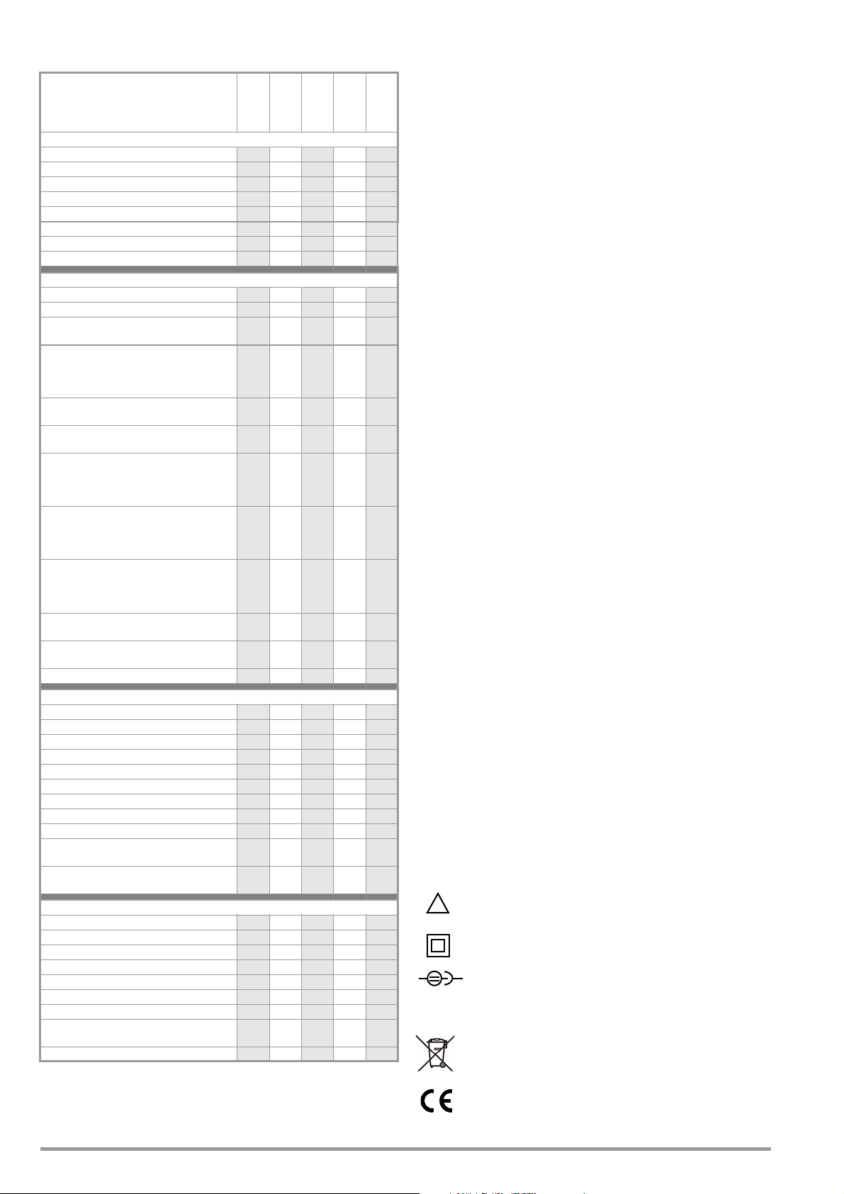
2.2 Overview of Features Included
!
with PROFITEST MASTER & SECULIFE IP Device Variants
PROFITEST ...
(Article Number)
PRO
TECH+
XTRA
(M520R)
(M520S)
M
MBASE+
Testing of residual current devices (RCDs)
measurement without tripping RCD ✓✓✓✓✓
U
B
Tripping time measurement
Measurement of tripping current I
Selective, SRCDs, PRCDs, type G/R ✓✓✓✓
AC/DC sensitive RCDs, type B, B+ and EV/MI —— ✓✓
Testing of IMDs ——— ✓
Testing of RCMs ——— ✓ —
Testing for N-PE reversal
Measurement of loop impedance Z
Fuse table for systems without RCDs ✓✓✓✓
Without tripping the RCD, fuse table ——✓✓
With 15 mA test current
RCD
Earthing resistance RE (mains operation)
I-U measuring method (2/3-wire measuring
method via measuring adapter: 2-wire/2-wire +
probe)
Earthing resistance RE (battery operation)
3 or 4-wire measurement via PRO-RE adapter
Soil resistivity
(4-wire measurement via PRO-RE adapter)
Selective earthing resistance RE (mains operation)
with 2-pole adapter, probe, earth electrode
and current clamp sensor (3-wire measuring
method)
Selective earthing resistance RE (battery operation)
with probe, earth electrode and current clamp
sensor (4-wire measuring method via PRO-RE
adapter and current clamp sensor)
Earth loop resistance R
with 2 clamps (current clamp sensor direct
and current clamp transformer via PRO-RE/2
adapter)
Measurement of equipotential bonding R
automatic polarity reversal
Insulation resistance R
variable or rising test voltage (ramp)
Voltage U
Special measurements
Leakage current (with clamp) I
Phase sequence ✓✓✓✓
Earth leakage resistance R
Voltage drop (ΔU) ✓✓✓✓
Standing-surface insulation Z
Meter start-up (kWh-Test) ✓✓✓✓—
Leakage current with PRO-AB adapter (IL)
Residual voltage test (Ures)
Intelligent ramp (ta + ΔI)
Electric vehicles at charging stations
(IEC 61851)
Report generation of fault simulations on
PRCDs with PROFITEST PRCD adapter
Features
Selectable user interface language
Memory (database for up to 50,000 objects) ✓✓✓✓
Automatic test sequence function ✓2✓ ✓✓
RS 232 port for RFID/barcode scanner
USB port for data transmission ✓✓✓✓
Interface for Bluetooth® ——✓✓
ETC user software for PC ✓✓✓✓
Measuring category: CAT III 600 V / CAT IV
300 V
DAkkS calibration ✓✓✓✓
1
The so-called live measurement is only advisable if there is no bias current within
the system. Only suitable for motor circuit breaker with low nominal current
2
currently available languages: D, GB, I, F, E, P, NL, S, N, FIN, CZ, PL
/ U
L-N
1
without tripping the
ρE (battery operation)
ELOOP
INS
/ U
L-P E
N-PE
F
/ Z
L-P E
L-N
— ✓ — ✓ —
— ✓ — ✓ —
— ✓ — ✓ —
(battery operation)
— ✓ — ✓ —
,
LO
,
/ f ✓✓✓✓
, I
L
AMP
E(ISO)
ST
———
———
———
——✓✓—
———
2
(M520N)
✓✓✓✓
✓✓✓✓
✓✓✓✓
✓✓✓✓
✓✓✓✓
✓✓✓✓
✓✓✓✓
✓✓✓✓
✓✓✓✓
✓✓✓✓
✓✓✓✓
✓✓✓✓
✓✓✓✓
✓✓✓✓
M
M
(M520P)
SECULIFE IP
✓
✓ —
✓ —
✓
—
3 Safety Features and Precautions
This instrument fulfills all requirements of applicable European and
national EC directives. We confirm this with the CE mark. The relevant declaration of conformity can be obtained from GMC-I
Messtechnik GmbH.
(M520U)
The electronic measuring and test instrument is manufactured
and tested in accordance with safety regulations IEC 61010-1/
DIN EN 61010-1/VDE 0411-1 and EN 61557.
✓
Safety of the operator, as well as that of the instrument, is only
✓
assured when it is used for its intended purpose.
✓
✓
Read the operating instructions thoroughly and carefully before using
✓
your instrument. Follow all instructions contained therein. Make sure that
the operating instructions are available to all users of the instrument.
✓
Tests may only be executed by a qualified electrician.
Grip and hold the test plug and test probes securely when they
✓
have been inserted, for example, into a socket. Danger of injury
✓
exists if tugging at the coil cord occurs, which may cause the test
✓
plug or test probes to snap back.
The measuring and test instrument may not be placed into service:
✓
• If the battery compartment lid has been removed
• If external damage is apparent
• If connector cable or measuring adapters are damaged
•If the instrument no longer functions flawlessly
• After a long period of storage under unfavorable conditions
(e.g. humidity, dust, temperature)
✓
Exclusion of Liability
When testing systems with RCCBs, the latter may switch off. This may
occur even though the test does not normally provide for it. Leakage currents may be present which, in combination with the test
current of the test instrument, exceed the shutdown threshold
value of the RCCB. PCs which are operated in proximity to such
RCCB systems may switch off as a consequence. This may result
in inadvertent loss of data. Before conducting tests, precautions
should therefore be taken to ensure that all data and programs
are adequately saved, and the computer should be switched off if
✓
necessary. The manufacturer of the test instrument assumes no
liability for any direct or indirect damage to equipment, comput-
✓
ers, peripheral equipment or data bases when performing tests.
✓
Opening of Equipment / Repair
The equipment may be opened only by authorized service per-
✓
sonnel to ensure the safe and correct operation of the equipment
✓
and to keep the warranty valid.
✓
Even original spare parts may be installed only by authorized ser-
✓
vice personnel.
✓
In case the equipment was opened by unauthorized personnel,
no warranty regarding personal safety, measurement accuracy,
✓
conformity with applicable safety measures or any consequential
damage is granted by the manufacturer.
Any warranty claims will be forfeited when the warranty seal has
been damaged or removed.
Meaning of Symbols on the Instrument
Warning concerning a point of danger
✓
✓
✓
✓
✓
✓
✓
✓
✓
(Attention, observe documentation!)
Protection class II device
Charging socket for extra-low direct voltage (charger Z502R)
Attention!
Only rechargeable batteries may be inserted when the charger is connected.
This device may not be disposed of with the trash. Further information regarding the WEEE mark can be
accessed on the Internet at www.gossenmetrawatt.com by entering the search term “WEEE”.
EC mark of conformity
6 GMC-I Messtechnik GmbH
Page 7
Any warranty claims will be forfeited when the warranty
Attention!
!
Note
Attention!
!
Attention!
!
XY123
2012-06
D-K
15080-01-01
Consecutive number
Registration number
Date of calibration (year – month)
Deutsche Akkreditierungsstelle GmbH – calibration lab
BAT
seal has been damaged or removed.
Calibration Seal (blue seal):
See also “Recalibration” on page 96.
Data Backup
We advise you to regularly transmit your stored data to a PC in
order to prevent potential loss of data in the test instrument.
We assume no responsibility for any data loss.
We recommend the following PC software programs for data
processing and management:
•ETC
• E-Befund Manager (Austria)
•Protokollmanager
• PS3 (documentation, management, report generation and
monitoring of deadlines)
• PC.doc-WORD/EXCEL (report and list generation)
• PC.doc-ACCESS (test data management)
4 Initial Start-Up
4.1 Preparation for use
Before putting the test instrument into service and using it for the
first time, the lamination sheets must be removed from the two
sensor surfaces (finger contacts) of the test plug in order to
ensure that contact voltage is reliably detected.
When Using a Battery Holder:
It is imperative that you pay attention to the correct polarity when inserting the rechargeable batteries. If a battery has been inserted with incorrect polarity, it is not
detected by the instrument and may lead to battery leakage.
Individual rechargeable batteries may only be charged
externally.
➭ Slide the new battery pack/filled battery holder into the battery
compartment. The holder can only be inserted to its proper
position.
➭ Replace the lid and re-tighten the screw.
4.3 Switching the Instrument On/Off
The test instrument is switched on by pressing the ON/START key.
The menu which corresponds to the momentary selector switch
position is displayed.
The instrument can be switched off manually by simultaneously
pressing the MEM and HELP keys.
After the period of time selected in the SETUP menus has elapsed,
the instrument is switched off automatically (see “Device Settings”, section 4.6.
4.4 Battery Test
If battery voltage has fallen below the permissible
lower limit, the pictograph shown at the right
appears. “Low Batt!!!” is also displayed along with a battery symbol. The instrument does not function if the batteries have been
depleted excessively, and no display appears.
4.5 Charging the Battery Pack in the Tester
4.2 Installing or Replacing the Battery Pack
Before opening the battery compartment, disconnect the
instrument from the measuring circuit (mains) at all poles!
See also section 20.2 on page 87 concerning charging
the Kompkt Akku Pack Master (Z502H) and the battery
charger Z502R.
Use Kompakt Akku Pack Master (Z502H), if possible, which is either
included in the standard equipment or available as an accessory, with
heat-sealed battery cells. Do not use any battery holders which can
be filled with individual batteries. This ensures that always a complete set of batteries is replaced and all rechargeable batteries are
inserted with correct polarity in order to prevent leakage from the
batteries.
Only use commercially available battery packs if you charge them externally. The quality of these sets cannot be verified and this may, in
unfavourable cases, lead to heating and deformation (during the
charging in the device).
Dispose the battery packs or the individual rechargeable batteries
in an environmentally sound fashion when their service life has
nearly expired (approx. 80% charging capacity).
➭ Loosen the slotted screw for the battery compartment lid on
the back and remove the lid.
➭ Remove the discharged battery pack or the battery holder.
Use only the charger Z502R to charge the Kompakt Akku-
Pack Master (Z502H) which has already been inserted into
the test instrument.
Make sure that the following conditions have been fulfilled before connecting the charger to the charging socket:
– Kompakt Akku-Pack Master (Z502H) has been
installed, no commercially available battery packs,
no individual rechargeable batteries, no standard
batteries
– The test instrument has been disconnected from the
measuring circuit at all poles
– The instrument must remain off during charging.
Refer to section 20.2.1 with regard to charging the battery pack
which has been inserted into the tester.
If the batteries or the battery pack have not been used or
recharged for a lengthy period of time (> 1 month), thus resulting
in excessive depletion:
Observe the charging sequence (indicated by LEDs at the charger) and initiate a second charging sequence if necessary (disconnect the charger from the mains and from the test instrument
to this end, and then reconnect it).
Please note that the system clock stops in this case and must be
set to the correct time after the instrument has been restarted.
GMC-I Messtechnik GmbH 7
Page 8
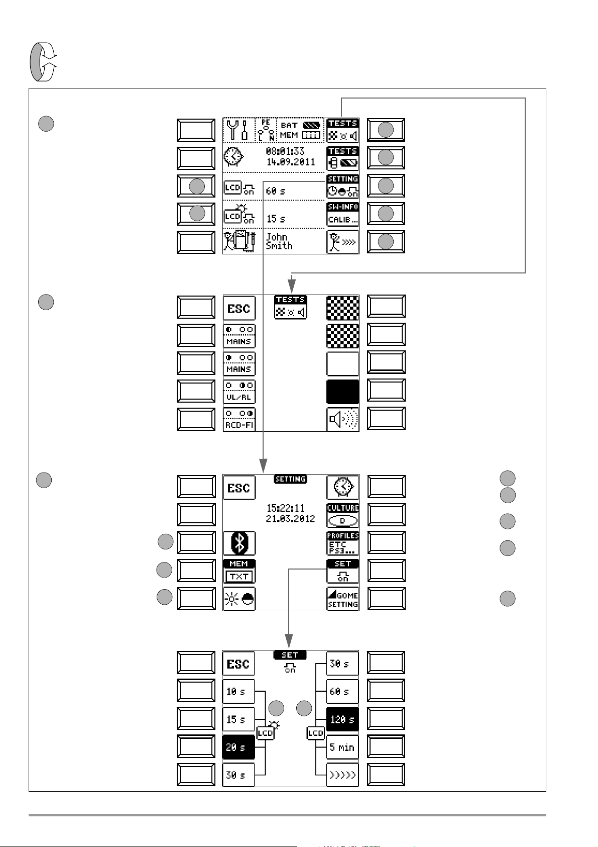
4.6 Device Settings
SETUP
LED and LCD test menu
Rotary switch balancing
Brightness/contrast menu
Software revision level
Calibration date
Display: date / time
Display: automatic shutdown
Display: automatic shutdown
of display illumination after 15 s.
of the tester after 60 s.
Time, language, profiles
1
2
3
4
and battery test menu
0b
0a
0
Return to main menu
MAINS LED: test green
MAINS LED: test red
UL/RL LED: test red
RCD-FI LED: test red
Cell test
Inverse cell test
Hide all pixels
Show all pixels
Acoustic signal test
1
Return to main menu
Increase brightness
Bluetooth
®
submenu →
DB-MODE submenu →
Brightness/contrast submenu →
Set time →
Profiles for
Default settings
→
distribution structures
→
User interface
language
→
3
3a
3b
3c
3d
3e
Set date →
On-time
for display illumination / tester
0b
Return to submenu
0a
Display Illumination On-time
Bluetooth® and Brightness Plus Contrast Settings Time, On-Time and Default Settings
Menu Selection for Operating Parameters
LED tests LCD and Acoustic Signal Tests
Test Instrument On-Time
Select inspector
(change via ETC)
3g
3f
5
No automatic shut-down,
continuously on
3h
logged in test technician
8 GMC-I Messtechnik GmbH
Page 9
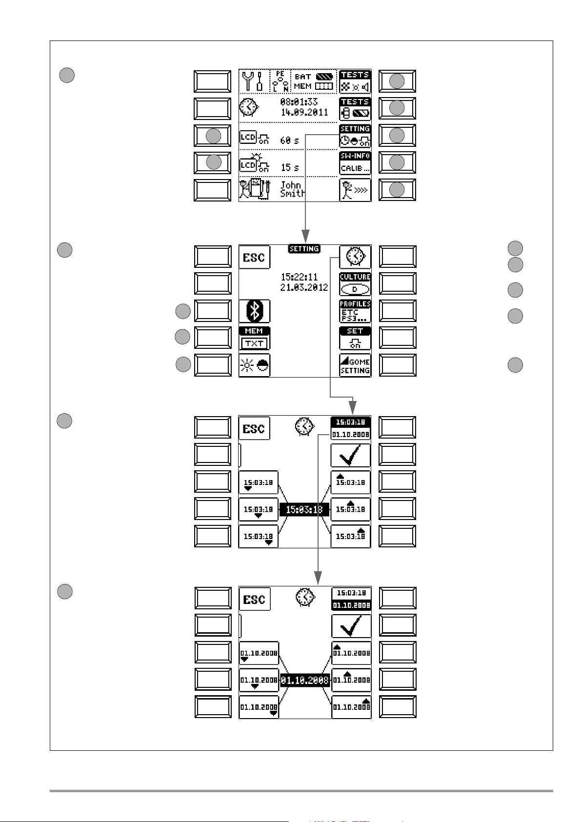
LED and LCD test menu
Rotary switch balancing
Brightness/contrast menu
Software revision level
Calibration date
Display: date / time
Display: automatic shutdown
Display: automatic shutdown
of display illumination after 15 s.
of the tester after 60 s. Time, language, profiles
1
2
3
4
and battery test menu
0b
0a
0
Return to main menu
Bluetooth
®
submenu →
Brightness/contrast submenu →
Set time →
Profiles for
Default settings
→
distribution structures
→
User interface
language
→
3
3a
3b
3c
3d
3e
Set date →
On-time
for display illumination / tester
Set time
Menu Selection for Operating Parameters
Bluetooth® and Brightness Plus Contrast Settings Set Time, Language, Profiles, Acoustic Signal
Set date
Select time
Increase
Increase
hours
Activate
settings
minutes
3a
Increase
seconds
Return to submenu
Decrease
Decrease
hours
minutes
Decrease
seconds
Select date
Increase
Increase
day
Activate
settings
month
3b
Increase
year
Return to submenu
Decrease
Decrease
day
month
Decrease
year
Enter and select a new inspector
(change/deletion via ETC only)
3h
3f
5
logged in test technician
DB-MODE submenu
→
3g
GMC-I Messtechnik GmbH 9
Page 10
Significance of Individual Parameters
Note
Note
Attention!
!
0a
0b
2
2
3c
3d3e3f
Return to previous menu
Increase brightness
Decrease brightness
Increase contrast
Decrease contrast
➭ Press ESC in order to return to the main menu.
Test Instrument On-Time
The period of time after which the test instrument is automatically
shut off can be selected here. This selection has a considerable
influence on the service life and the charging status of the batteries.
On-Time for LCD Illumination
The period of time after which LCD illumination is automatically
shut off can be selected here. This selection has a considerable
influence on the service life and the charging status of the batteries.
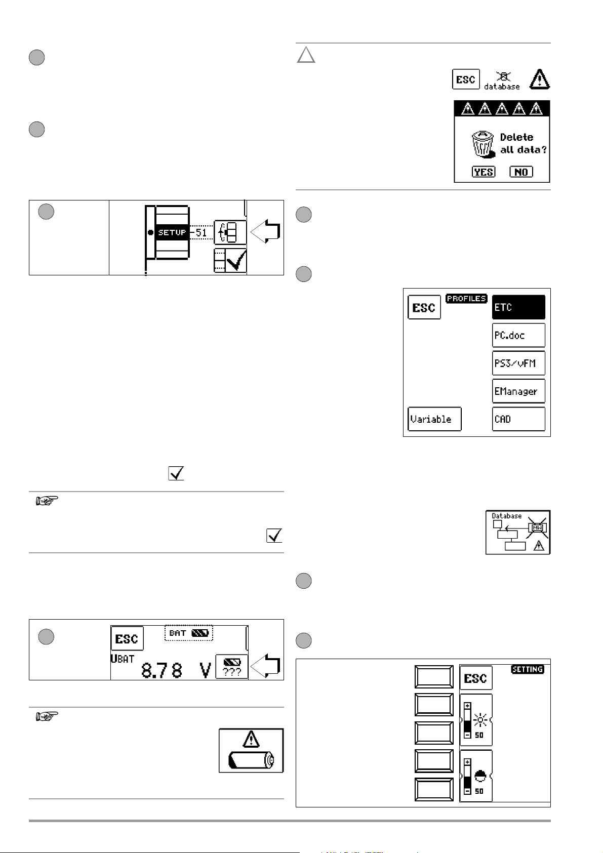
Submenu: Rotary Switch Balancing
Proceed as follows in order to precision adjust the rotary switch:
1 Press the TESTS Rotary Switch / Battery Test softkey in order to
access the rotary switch balancing menu.
2 Then press the softkey with the rotary switch symbol.
3 Turn the rotary switch clockwise to the next respective measuring
function (IDN first after SETUP).
4 Press the softkey which is assigned to the rotary switch at the LCD.
After pressing this softkey, the display is switched to the next mea-
suring function. Labeling in the LCD image must correspond to the
actual position of the rotary switch.
level bar in the LCD image of the rotary switch should be
The
located in the middle of the black field, and is supplemented at
the right-hand side with a number within a range of -1 to 101.
This value should be between 45 and 55. In the case of -1 or 101,
the position of rotary knob does not coincide with the measuring
function selected at the LCD.
5 If the displayed value is not within this range, readjust the
position by pressing the readjust softkey. A brief acoustic
signal acknowledges readjustment.
If labeling in the LCD image of the rotary switch does not
correspond with its actual position, a continuous acoustic signal is generated as a warning when the readjust
softkey is pressed.
6 Return to point 2 and continue. Repeat this procedure until all
rotary switch functions have been tested, and if necessary
readjusted.
➭ Press ESC in order to return to the main menu.
Submenu: Battery Level Query
Data and sequences are lost
when the language, the profile or
DB mode is changed, or if the instrument is reset to default values!
Back up your structures,
measurement data and sequences to a PC before
pressing the respective key.
The prompt window shown at
the right asks you to confirm
deletion.
User Interface Language (CULTURE)
➭ Select the desired country setup with the appropriate country
code. Attention: all existing structures, data and sequences are de-
leted, see note above!
Profiles for Distributor Structures (PROFILES)
The profiles are laid out in
a tree structure. The tree
structure for the utilized
PC evaluation program
may differ from that of the
PROFITEST MASTER. For
this reason, the
PROFITEST MASTER provides the user with the
opportunity of adapting
this structure.
Selecting a suitable profile
determines which object
combinations are made
possible. For example,
this makes it possible to
create a distributor which is subordinate to another, or to save a
measurement to a given building.
➭ Select the PC evaluation program you intend to use.
Attention: all existing structures, data and sequences are deleted,
see note above!
If you have not selected a suitable PC evaluation program and, for example, if measured
value storage to the selected location within the
structure is not possible, the pop-up window
shown at the right appears.
Default Settings (GOME SETTING)
The test instrument is returned to its original default settings when
this key is activated.
Attention: all existing structures, data and sequences are deleted, see
note above!
Adjusting Brightness and Contrast
If battery voltage has dropped to 8.0 V or less, the UL/RL LED lights
up red and an acoustic signal is generated as well.
10 GMC-I Messtechnik GmbH
Measuring Sequence
If battery voltage drops to below 8.0 V
during the course of a measuring
sequence, this is indicated by means of
a pop-up window only. Measured values are invalid. The measurement results cannot be
saved to memory.
Page 11
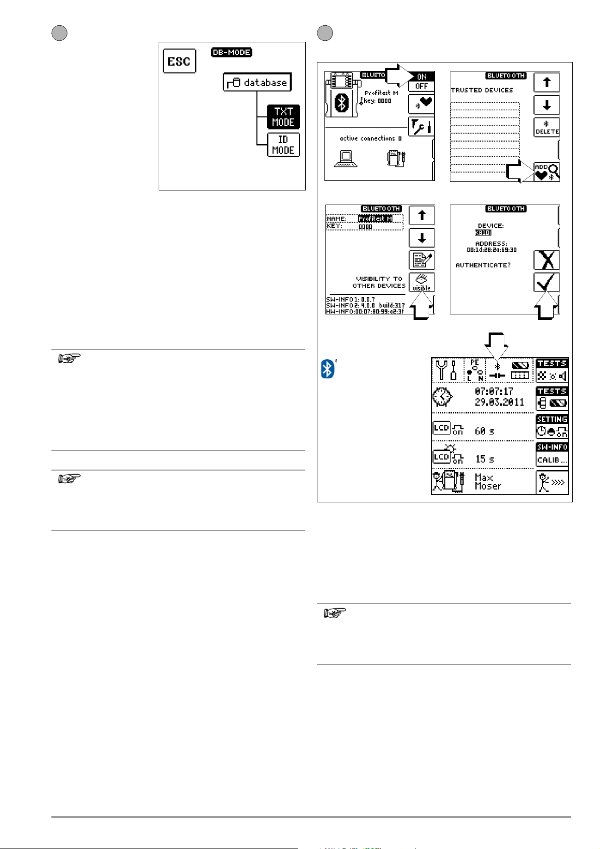
DB MODE – Presenting the Database in Text Mode or ID Mode
Note
Note
Note
3g
3h
When Bluetooth® is
active (= ON), the
Bluetooth
®
icon
appears in the
header instead of BAT, and
an interface icon appears
instead of MEM.
A closed interface icon indicates
an active Bluetooth connection
with data transmission.
Figure 1
Figure 2
Figure 3 Figure 4
The DB MODE functions are
available as of firmware version 01.05.00 of the test
instrument and as of ETC
version 01.31.00.
Creating Structures in TXT MODE
By default, the database in the test instrument is set to text mode,
„TXT“ is indicated in the header. You can create structural elements in the test instrument und add designations in plain text,
e. g. Customer XY, Distributor XY and Electrical Circuit XY.
Creating Structures in ID MODE
Alternatively, you can work in the ID mode. „ID“ is indicated in the
header. You can create structural elements in the test instrument
which can be labelled with ID numbers at your discretion.
Switching Bluetooth® On/Off (
only)
MTECH+/MXTRA/
SECULIFE IP
When data are transferred from the test instrument to the
PC or ETC, ETC always retains the presentation (TXT or
ID mode) selected in the test instrument.
When data are transferred from the PC or ETC to the test
instrument, the test instrument always retains the presentation selected in ETC.
So, the respective receiver of the data always adopts the
presentation of the sender.
In the test instrument, structures can either be created in
text mode or in ID mode.
In the ETC software, however, designations and ID numbers are always allocated.
If no texts or ID numbers have been allocated when creating the
structures in the test instrument, ETC generates the missing
entries automatically. They can be subsequently edited in the ETC
software and transferred back to the test instrument if required.
If your PC is equipped with a Bluetooth® interface, wireless communication is possible between the MTECH+, MXTRA or SECULIFE IP
and ETC user software for the transfer of data and test structures.
One-time only authentication of the respective PC with the test
instrument is a prerequisite for wireless data exchange. The function selector switch must be in the SETUP position to this end.
The correct Bluetooth
before each data transmission sequence.
Activate the Bluetooth® interface at the test instrument
during data transmission only. Interface power consumption reduces battery service life when activated continuously.
®
COM port must also be selected in ETC
GMC-I Messtechnik GmbH 11
If several test instruments are within range during authentication,
the respective name should be changed in order to rule out the
possibility of a mix-up. Blanks may not be used. The default pin
code, namely “0000”, can be changed, but this is unnecessary as
a rule. As shown in figure 3, the MAC address of the test instrument is displayed in the footer as hardware information.
Render your test instrument visible prior to authentication, and
subsequently invisible for security reasons.
Page 12
Steps Required for Authentication
Note
4
5
Make sure that the test instrument is within range of the PC
(roughly 5 to 8 meters). Activate Bluetooth
(see figure 1) and at your PC.
The function selector switch must be in the SETUP position to this end.
Make sure that the test instrument (see figure 3) and your PC are
visible for other Bluetooth
®
devices:
In the case of the test instrument, the word “visible” must be dis-
played underneath the eye symbol.
Use your Bluetooth
®
PC driver software to add a new Bluetooth®
device. In most cases, this is accomplished with the help of the
“Add new connection” or “Add Bluetooth® device” button.
The following steps may vary, depending on which Bluetooth
driver software is used. Basically, a PIN code must be entered at
the PC. The default setting for the PIN code is “0000”, and is displayed in the main Bluetooth
®
menu (see figure 1) at the test instrument. Subsequently, or previously, an authentication message
must be acknowledged at the test instrument (see figure 4).
If authentication has been successful, a corresponding message
appears at the test instrument. Furthermore, the authenticated
PC is displayed in the “Trusted Devices” menu at the test instrument (see figure 2).
The MTECH+, MXTRA or the SECULIFE IP should now also be listed
as a device in your Bluetooth
tion is also provided here regarding the utilized COM port. With
the help of your Bluetooth
®
PC driver software. Further informa-
®
PC driver software, you’ll need to find
out which COM port is used for the Bluetooth
port is frequently displayed after authentication, but if this is not
the case, this information provided by your Bluetooth® PC driver
software.
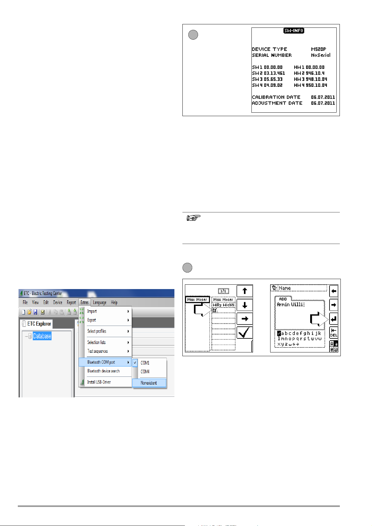
ETC includes a function for automatically ascertaining the utilized COM port
after successful authentication has been completed (see screenshot below).
If the test instrument is within range of your PC (5 to 8 meters),
wireless data exchange can now be initiated with the help of ETC
by clicking Bluetooth
®
in the “Extras” menu. The number of the correct COM port (e.g. COM40) must be entered to ETC when data
exchange is started (see screenshot below).
Alternatively, the COM port number can be selected automatically by clicking
the “Find Bluetooth Device” item in the menu.
®
at the test instrument
®
connection. This
®
PC
Firmware Revision and Calibration Information (example)
➭ Press any key in order to return to the main menu.
Firmware Update with the MASTER Updater
The layout used for the entire range of the test instruments makes
it possible to adapt instrument software to the latest standards
and regulations. Beyond this, suggestions from customers result
in continuous improvement of the test instrument software, as
well as new functions.
In order to assure that you can take advantage of all of these benefits without delay, the MASTER Updater allows you to quickly
and completely update your test instrument software on-site.
The user interface can be set to either English, German or Italian.
As a registered user, you’re entitled to download the
MASTER Updater and the current firmware version free of
charge from the myGMC page.
Entering and Selecting a New Inspector
See also section 5.7 page 15 regarding the entry of a text.
12 GMC-I Messtechnik GmbH
Page 13
5 General Notes
Note
Note
Attention!
!
5.1 Connecting the Instrument
For systems with earthing contact sockets, connect the instrument to the mains with the test plug to which the appropriate,
country-specific plug insert is attached. Voltage between phase
conductor L and the PE protective conductor may not exceed
253 V!
Poling at the socket need not be taken into consideration. The
instrument detects the positions of phase conductor L and neutral conductor N and automatically reverses polarity if necessary.
This does not apply to the following measurements:
– Voltage measurement in switch position U
– Insulation resistance measurement
– Low-value resistance measurement
The positions of phase conductor L and neutral conductor N are
identified on the plug insert.
If measurement is to be performed at three-phase outlets, at distribution cabinets or at permanent connections, the measuring
adapter must be attached to the test plug (see also table 16.1).
Connection is established with the test probes: one at PE or N
and the other at L.
The 2-pole measuring adapter must be expanded to 3 poles with
the included measurement cable for the performance of phase
sequence testing.
Contact voltage (during RCCB testing) and earthing resistance
can be, and earth-electrode potential, standing surface insulation
resistance and probe voltage must be measured with a probe.
The probe is connected to the probe connector socket with a
4 mm contact protected plug.
5.2 Automatic Settings, Monitoring and Shut-Off
The test instrument automatically selects all operating conditions
which it is capable of determining itself. It tests line voltage and
frequency. If these lie within their valid nominal ranges, they
appear at the display panel. If they are not within nominal ranges,
prevailing voltage (U) and frequency (f) are displayed instead of U
and f
.
N
Contact voltage which is induced by test current is monitored for
each measuring sequence. If contact voltage exceeds the limit
value of > 25 V or > 50 V, measurement is immediately interrupted. The U
If battery voltage falls below the allowable limit value the instrument
cannot be switched on, or it is immediately switched off.
The measurement is interrupted automatically, or the measuring
sequence is blocked (except for voltage measuring ranges and
phase sequence testing) in the event of:
• Impermissible line voltages (< 60 V, > 253 V / > 330 V /
> 440 V or > 550 V) for measurements which require line voltage
• Interference voltage during insulation resistance or low resistance measurements
• Overheating at the instrument.
As a rule, excessive temperatures only occur after approximately 50 measurement sequences at intervals of 5 seconds,
when the rotary selector switch is set to the Z
position.
If an attempt is made to start a measuring sequence, an
appropriate message appears at the display panel.
The instrument only switches itself off automatically after completion of an automatic measuring sequence, and after the predetermined on-time has expired (see sectionl 4.3). On-time is reset to
its original value as defined in the setup menu, as soon as any key
or the rotary selector switch is activated.
The instrument remains on for approximately 75 seconds in addition to the preset on-time for measurements with rising residual
current in systems with selective RCDs.
The instrument always shuts itself off automatically!
LED lights up red.
L/RL
L-PE
oder Z
L-N
5.3 Measurement Value Display and Memory
The following appear at the display panel:
• Measurement values with abbreviations and units of measure
• Selected function
• Nominal voltage
• Nominal frequency
• Error messages
Measurement values for automatic measuring sequences are
stored and displayed as digital values until the next measurement
sequence is started, or until automatic shut-off occurs.
If the upper range limit is exceeded, the upper limit value is displayed and is preceded by the “>” symbol (greater than), which
indicates measurement value overrun.
The depiction of LEDs in these operating instructions
may vary from the LEDs on the actual instrument due to
product improvements.
5.4 Testing Earthing Contact Sockets for Correct Connection
The testing of earthing contact sockets for correct connection
prior to protective measures testing is simplified by means of the
instrument’s error detection system.
The instrument indicates improper connection as follows:
• Impermissible line voltage (< 60 V or > 253 V):
The MAINS/NETZ LED blinks red and the measuring
sequence is disabled.
• Protective conductor not connected or potential to earth ≥ 50 V
at ≥ 50 Hz (switch position U – single-phase measurement):
If the contact surfaces are touched (finger contact*) while PE is
being contacted (via the country-specific plug insert, e.g.
SCHUKO, as well as via the PE test probe at the 2-pole
adapter) PE appears (only after a test sequence has been
started). The U
N
the test plug must be touched directly with the finger/palm without
any skin protection applied, see also section 4.1.
* for reliably detecting the contact voltages, both sensor surfaces at
• Neutral conductor N not connected (during mains dependent
measurements):
The MAINS/NETZ LED blinks green.
• One of the two protective contacts is not connected:
This is checked automatically during testing for contact current U
leads to one of the following displays, depending upon poling
. Poor contact resistance at one of the contacts
IΔN
of the plug:
– Display at the connection pictograph:
PE interrupted (x), or underlying protective
conductor bar interrupted with reference
to keys at the test plug
Cause: voltage measuring path interrupted
Consequence: measurement is disabled
– Display at the connection pictograph:
Overlying protective conductor bar interrupted with reference to keys at the test
plug
Cause: current measuring path interrupted
Consequence: no measured value display
See also “LED Indications, Mains Connections and
Potential Differences” beginning on page 73.
Reversal of N and PE in a system without RCCBs cannot
be detected and is not indicated by the instrument.
In a system including an RCCB, the RCCB is tripped
during “contact voltage measurement without RCCB
tripping” (automatic Z
PE are reversed.
and RCD/FI LEDs light up red as well.
L/RL
measurement), insofar as N and
L-N
GMC-I Messtechnik GmbH 13
Page 14
5.5 Help Function
1
2
2
3
4
4
5
6
2
4
3
5
6
The following information can be displayed for each switch position and basic function after it has been selected with the rotary selec-
tor switch:
• Wiring diagram
• Measuring range
• Nominal range of use and measuring uncertainty
• Nominal value
➭ Press the HELP key in order to query online help:
➭ If several pages of help are available for the respective mea-
suring function, the HELP key must be pressed repeatedly.
➭ Press the ESC key in order to exit online help.
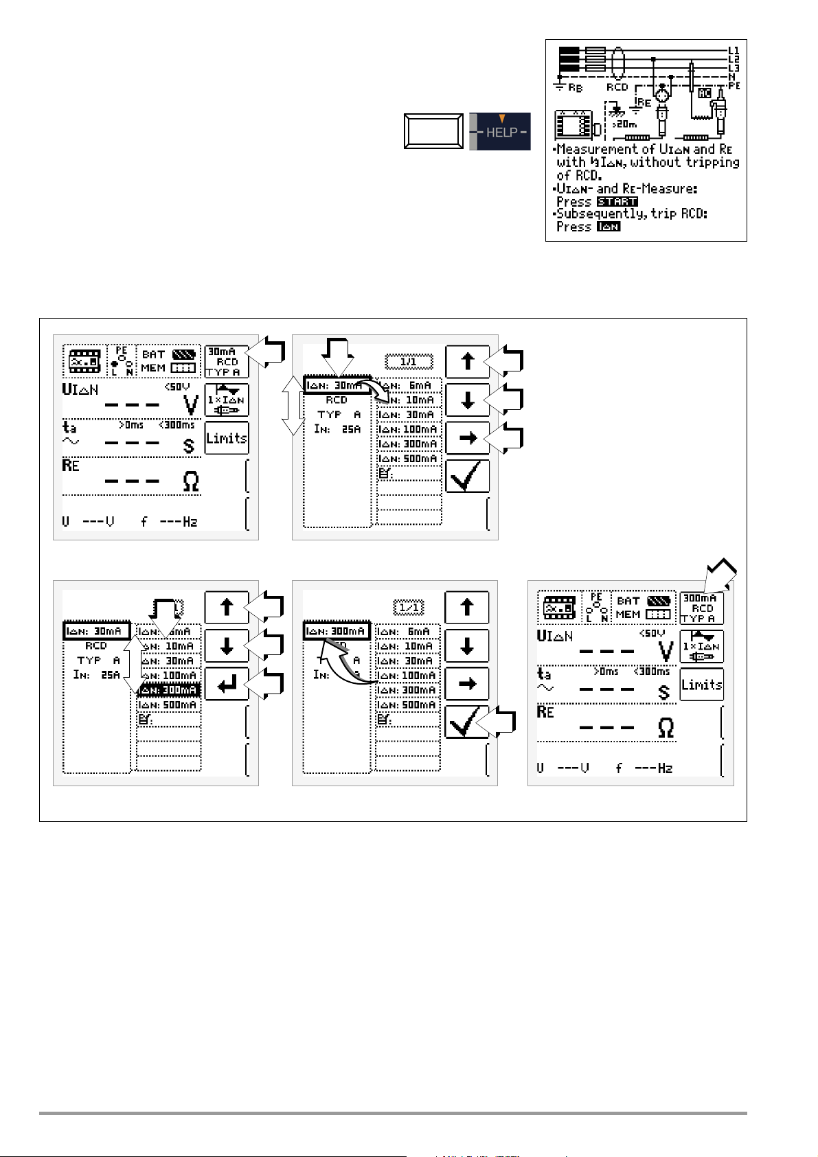
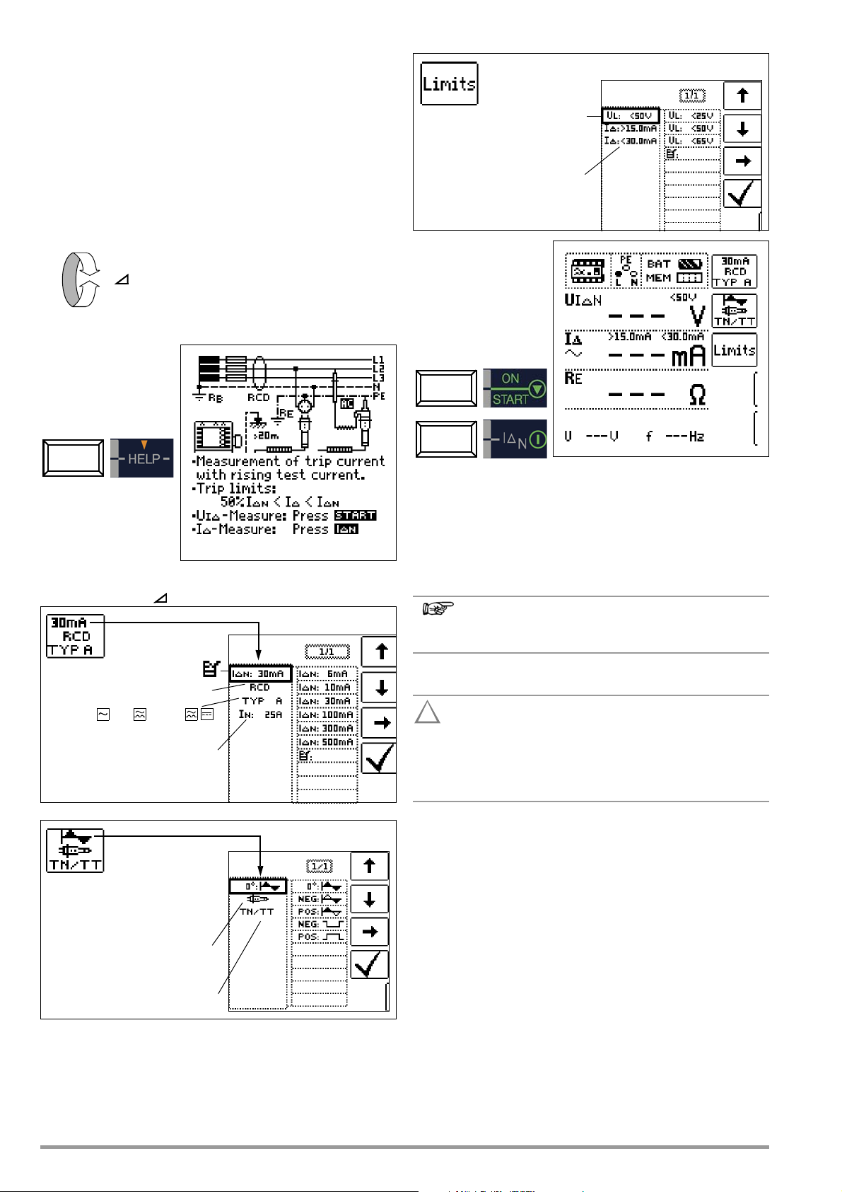
5.6 Setting Parameters or Limit Values using RCD Measurement as an Example
1 Access the submenu for setting the desired parameter.
2 Select a parameter using the ↑ or ↓ scroll key.
3 Switch to the setting menu for the selected parameter with the → scroll
key.
4 Select a setting value using the ↑ or ↓ scroll key.
5 Acknowledge the setting value with the ↵ key. This value is transferred to
the setting menu.
6 The setting value is not permanently accepted for the respective measure-
ment until
menu. You can return to the main menu by pressing ESC instead of
without accepting the newly selected value.
✓ is pressed, after which the display is returned to the main
✓,
Parameter Lock (plausibility check)
Individually selected parameter settings are checked for plausibility before transfer to the measurement window.
If you select a parameter setting which doesn’t make sense in
combination with other parameter settings which have already
been entered, it’s not accepted. The previously selected parameter setting remains unchanged.
Remedy: Select another parameter setting.
14 GMC-I Messtechnik GmbH
Page 15
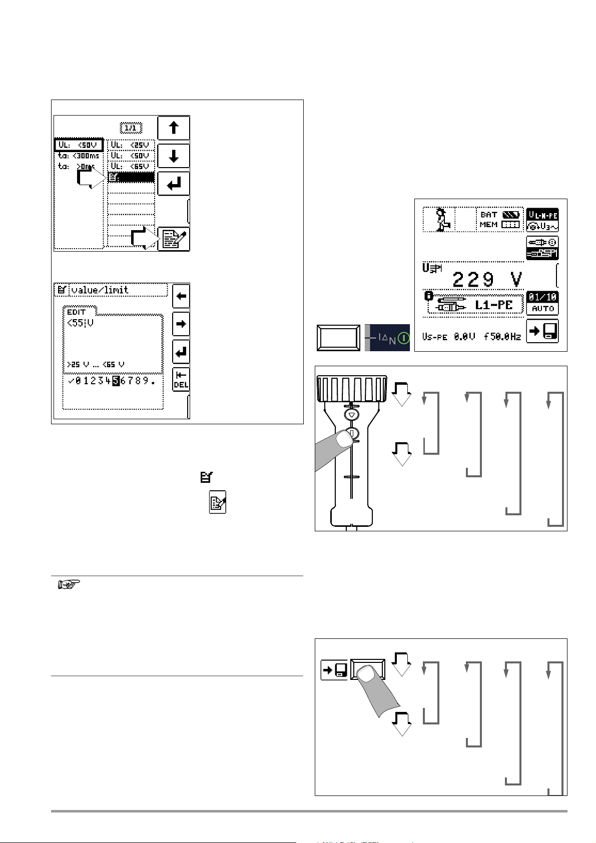
5.7 Freely Selectable Parameter Settings or Limit Values
Note
Select value / U/M.
Select value / U/M.
↵ Accept value / U/M.
Delete characters.
✓ Save value (to list).
Select editable value.
Select editable value.
Select the EDIT menu.
3
4
L1-N
L2-N
L3-N
L1-L2
L2-L3
L1-L3
L1-PE
L2-PE
L3-PE
N-PE
L+N-PE
L1-N
L2-N
L3-N
L1-L2
L2-L3
L1-L3
Z
L-PE
Z
L-N
L1-PE
L2-PE
L3-PE
R
iso
L1-PE
L2-PE
L3-PE
N-PE
L1-N
L2-N
L3-N
L1-L2
L2-L3
L1-L3
U
L1-N
L2-N
L3-N
L1-L2
L2-L3
L1-L3
L1-PE
L2-PE
L3-PE
N-PE
L+N-PE
L1-N
L2-N
L3-N
L1-L2
L2-L3
L1-L3
Z
L-PE
Z
L-N
L1-PE
L2-PE
L3-PE
R
iso
L1-PE
L2-PE
L3-PE
N-PE
L1-N
L2-N
L3-N
L1-L2
L2-L3
L1-L3
U
In addition to fixed values, other values can be freely selected
within predefined limits for certain parameters, if the symbol for
the EDIT menu (3) appears at the end of the list of setting values.
Freely Selecting a Limit Value or Nominal Voltage
5.8 2-Pole Measurement with Fast or Semiautomatic Polarity Reversal
Fast, semiautomatic polarity reversal is possible for the following
measurements:
• Voltage U
• Loop impedance Z
• Internal line resistance measurement Z
• Insulation resistance, R
LP-E
L-N
INS
Fast Polarity Reversal at the Test Plug
The polarity parameter is set to AUTO.
Fast and convenient switching amongst all polarity variants, or
switching to the parameter settings submenu, is possible by
pressing the I
key at the instrument or the test plug.
ΔN
1 Open the submenu for setting the desired parameter (no figure, see section
5.6).
2 Select parameter (U
5.6).
3 Select a setting value with the help of the icon and the ↑ or ↓ scroll
key.
4 Select the edit menu: Press the key with the icon.
5 Select the desired value or unit of measure with the LEFT or RIGHT scroll
key. The value or unit of measure is accepted by pressing the ↵ key. The
entire value is acknowledged by selecting
The new limit value or nominal value is added to the list.
GMC-I Messtechnik GmbH 15
Observe predefined limits for the new setting value.
New, freely selected limit values or nominal values
included in the parameters list can be deleted/edited at
the PC with the help of ETC software.
When the upper limit value is exceeded, this value is
accepted (in the example: 65 V), when the limit value is
fallen short of, the predefined lower limit value (25 V) is
accepted.
) using the ↑ or ↓ scroll key (no figure, see section
L
✓ and then pressing the ↵ key.
Semiautomatic Polarity Reversal in Memory Mode
The polarity parameter is set to AUTO.
If testing is to be conducted with all polarity variants, automatic
polarity changing takes place after each measurement when the
“Save” button is pressed.
Polarity variants can be skipped by pressing the I
instrument or the test plug.
key at the
ΔN
Page 16
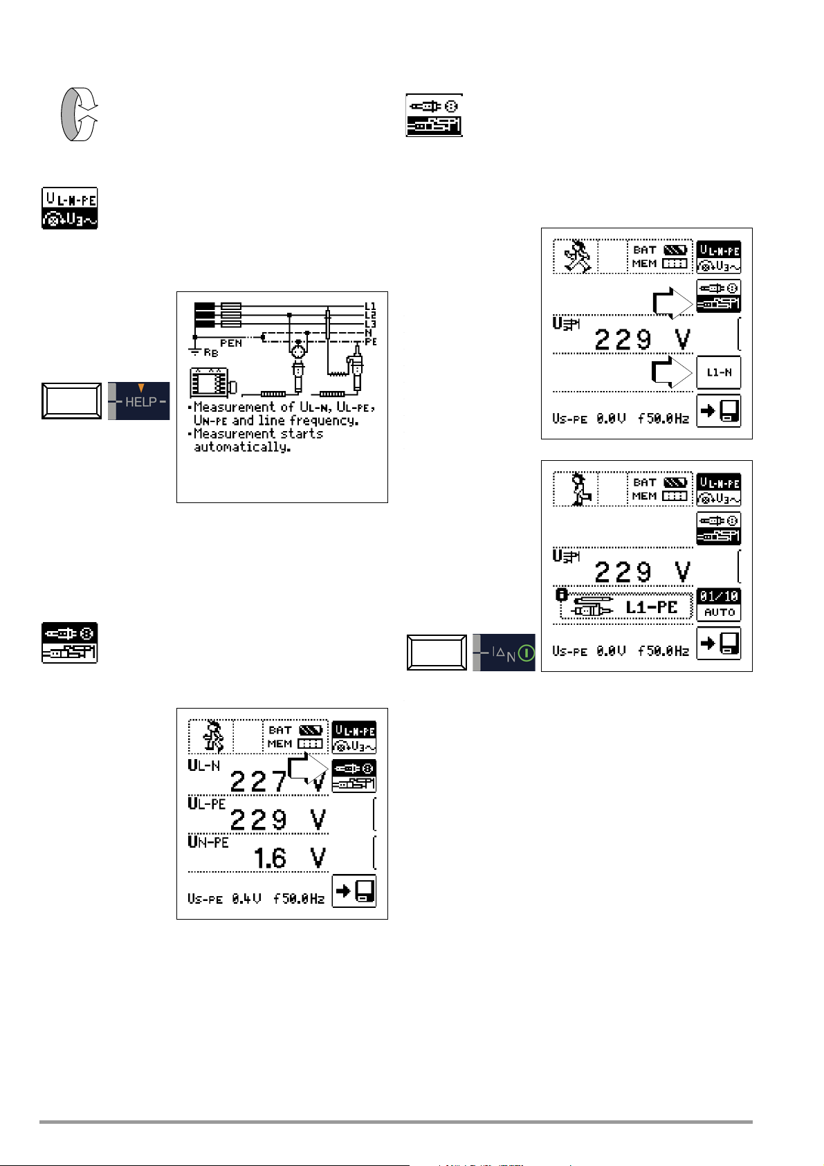
6 Measuring Voltage and Frequency
U
2
1
Select Measuring Function
Switch Between Single and 3-Phase Measurement
Press the softkey shown at the left in order to switch
back and forth between single and 3-phase measurement. The selected phase measurement is displayed inversely (white on black).
6.1 Single-Phase Measurement
Connection
6.1.2 Voltage between L – PE, N – PE and L – L with 2-Pole Adapter Connection
Press the softkey shown at the left in order to switch
back and forth between the country-specific plug
insert, e.g. SCHUKO, and the 2-pole adapter. The
selected connection type is displayed inversely
(white on black).
Refer to section 5.8 regarding 2-pole measurement with fast or
semiautomatic polarity reversal.
A probe must be used in order to measure probe voltage U
6.1.1 Voltage Between L and N (U
a
nd N and PE
(U
) with Country-Specific Plug Insert, e.g.
N-PE
L-N
),
L and PE
(U
L-P E
)
SCHUKO
Press the softkey shown at the left in order to switch
back and forth between the country-specific plug
insert, e.g. SCHUKO, and the 2-pole adapter. The
selected connection type is displayed inversely
(white on black).
S-PE
.
16 GMC-I Messtechnik GmbH
Page 17
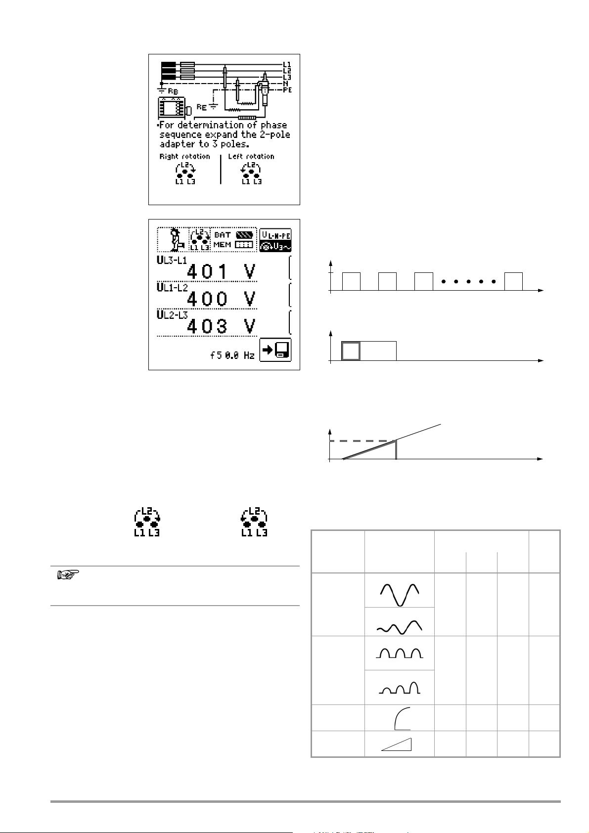
6.2 3-Phase Measurement (line-to-line voltage) and Phase
Note
Clockwise
Counter-Clockwise
I
ΔN
3
-------
I
ΔN
(measurement up to 1000 ms)
t
a
I
a
t
Sequence
Connection
The measuring adapter
(2-pole) is required in
order to connect the
instrument, and can be
expanded to a 3-pole
measuring adapter with
the included measurement cable.
➭ Press softkey U3~.
7 Testing RCDs
The testing of residual current devices (RCDs) includes:
• Visual inspection
•Testing
• Measurement
Use the test instrument for testing and measurement.
Measuring Method
The following must be substantiated by generating a fault current
downstream from the RCD:
• That the RCD is tripped no later than upon reaching its nominal fault current value
• That the continuously allowable contact voltage value U
agreed upon for the respective system is not exceeded
This is achieved by means of:
• Contact voltage measurement, 10 measurements with fullwaves and extrapolation of I
ΔN
L
A clockwise phase
sequence is required at all 3-phase electrical outlets.
• Measurement instrument connection is usually problematic with
CEE outlets due to contact problems.
Measurements can be executed quickly and reliably without contact problems with the help of the Z500A variable plug adapter
set available from GMC.
• Connection for 3-wire measurement, plug L1-L2-L3 in clockwise
direction as of PE socket
Direction of rotation is indicated by means of the following displays:
See section 18 regarding all indications for the mains
connection test.
• Substantiation of tripping within 400 ms or 200 ms with IΔN
• Substantiation of tripping with current rising residual current:
This value must be between 50% and 100% of I
about 70%).
(usually
ΔN
• No premature tripping with the test instrument, because testing is begun with 30% residual current (if no bias current
occurs within the system).
RCD/FI Table Type of Differential
Current
Suddenly occurring
Alternating
current
Slowly rising
Correct RCD/RCCB
Function
Typ e AC
✔
Typ e A, F
✔✔✔
Typ e B*/
B+*
Type EV*
Voltage Polarity
If the installation of single-pole switches to the neutral conductor
is prohibited by the standards, voltage polarity must be tested in
order to assure that all existing single-pole switches are installed
to the phase conductors.
Pulsating direct current
Direct current
Direct current
up to 6 mA
* PROFITEST MTECH+, PROFITEST MXTRA & SECULIFE IP
Suddenly occurring
Slowly rising
✔✔✔
✔✔
GMC-I Messtechnik GmbH 17
✔
Page 18
Test Standard
Note
Attention!
!
S
I
ΔN
Nominal residual
Type 1: RCD, SRCD, PRCD etc.
Nominal current: 6 ... 125 A
Type 2: AC , A/F , B/B+ *
EV/MI
* Type B/B+/EV/MI = AC/DC sensitive
current:
10 ... 500 mA
Phase displacement: 0°/180°
X times tripping current:
Negative/positive half-wave
Negative/positive direct current
1, 2, 5 (I
ΔN
max. 300 mA)
Waveform:
Connection:
without/with probe
System type:
TN/TT, IT
Contact voltage:
Time to trip:
< 25 V, < 50 V, < 65 V
The following must be substantiated per DIN VDE 0100 part 600:
2008:
– Contact voltage occurring at nominal residual current may not
exceed the maximum allowable value for the system.
– Tripping of the RCCB must occur within 400 ms (1000 ms for
selective RCDs) at nominal residual current.
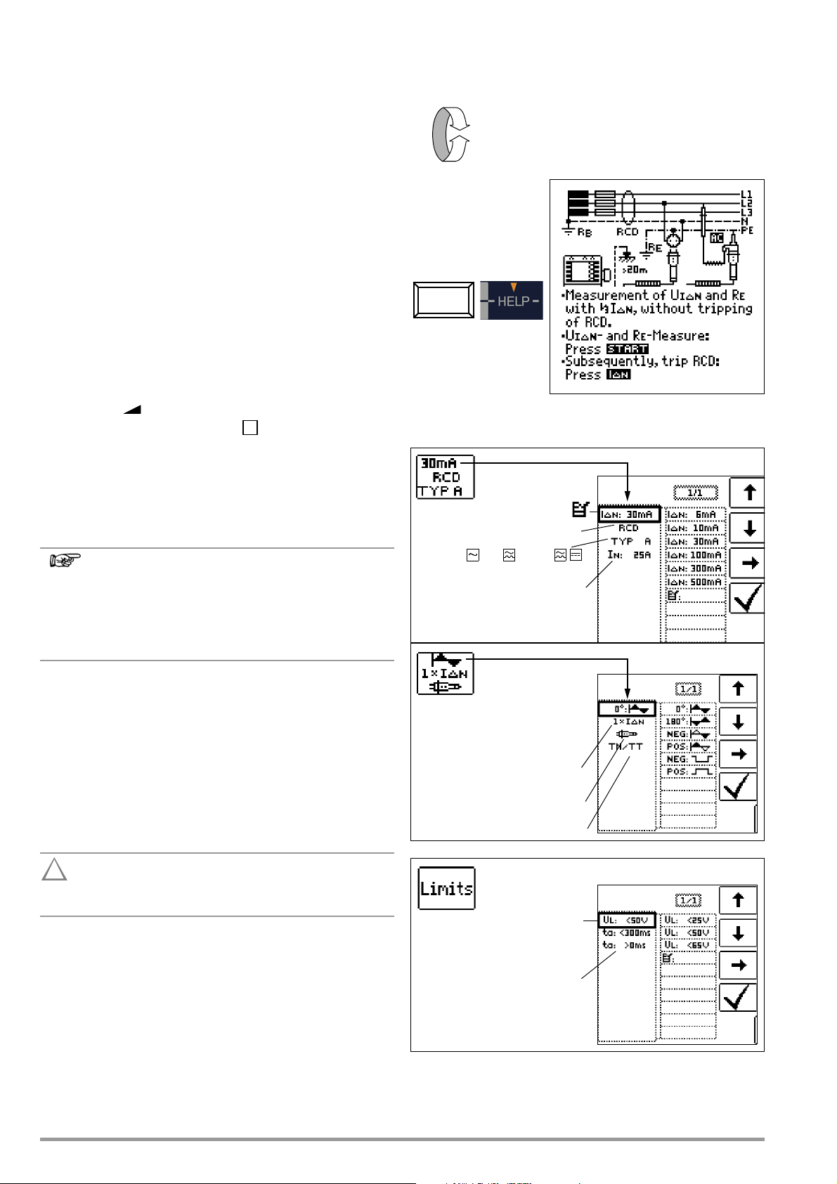
7.1 Measuring Contact Voltage (with reference to nominal
residual current) with
1
/3 Nominal Residual Current and
Tripping Test with Nominal Residual Current
Select Measuring Function
Important Notes
•The PROFITEST MASTER allows for simple measurements at all
types of RCDs. Select RCD, SRCD, PRCD etc.
• Measurement must be executed at one point only per RCD
(RCCB) within the connected electrical circuits. Low-resistance continuity must be substantiated for the protective conductor at all other connections within the electrical circuit (R
or U
).
B
• The measuring instruments often display a contact voltage of
0.1 V in TN systems due to low protective conductor resistance.
• Be aware of any bias currents within the system. These may
cause tripping of the RCDs during measurement of contact
voltage U
ments with rising current:
Display = I
• Selective RCDs identified with an can be used as the sole
means of protection for automatic shutdown if they adhere to
the same shutdown conditions as non-selective RCDs (i.e.
t
< 400 ms). This can be substantiated by measuring shut-
a
down time.
• Type B RCDs may not be connected in series with type A
RCDs.
, or may result in erroneous displays for measure-
B
- I
F
bias_current
Bias Magnetization
Only AC measurements can be performed with the 2pole adapter. Suppression of RCD tripping by means of
bias magnetization with direct current is only possible via
a country-specific plug insert, e.g. SCHUKO, or the 3pole adapter.
LO
Connection
Set Parameters for I
ΔN
Measurement With or Without Probe
Measurements can be performed with or without a probe.
Measurements with probe require that the probe and reference
earth are of like potential. This means that the probe must be
positioned outside of the potential gradient area of the earth electrode (R
The distance between the earth electrode and the probe should
be at least 20 m.
The probe is connected with a 4 mm contact protected plug.
In most cases this measurement is performed without probe.
Testing for the absence of voltage at the probe can be performed
with the U
18 GMC-I Messtechnik GmbH
) in the RCD safety circuit.
E
The probe is part of the measuring circuit and may carry
a current of up to 3.5 mA in accordance with VDE 0413.
function (see also section 6.1 on page 16).
PROBE
Page 19
1) Measuring Contact Current Without Tripping the RCD
Attention!
!
Note
Note
Attention!
!
Measuring Method
The instrument uses a measuring current of only 1/3 nominal
residual current for the determination of contact voltage U
which occurs at nominal residual current. This prevents tripping of
IΔN
the RCCB.
This measuring method is especially advantageous, because
contact voltage can be measured quickly and easily at any electrical outlet without tripping the RCCB.
The usual, complex measuring method involving testing for the
proper functioning of the RCD at a given point, and subsequent
substantiation that all other systems components requiring protection are reliably connected at low resistance values to the
selected measuring point via the PE conductor, is made unnecessary.
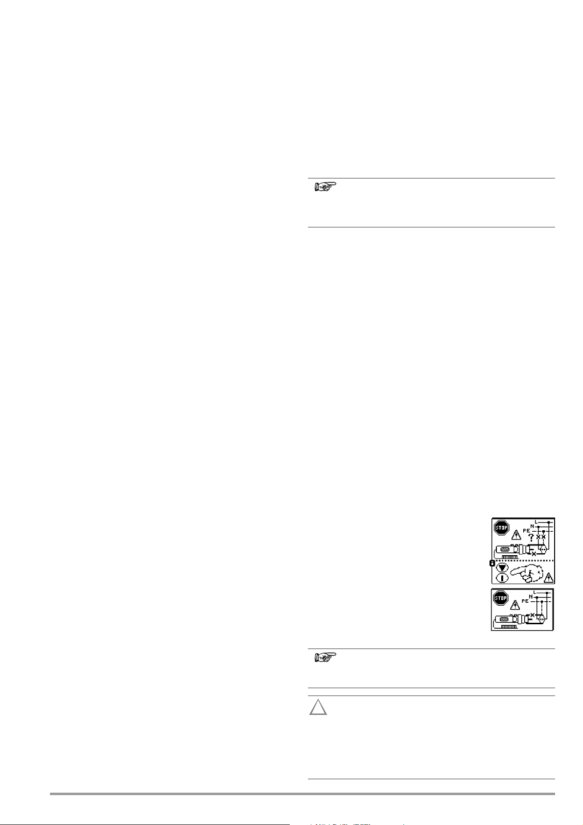
N-PE Reversal Test
Additional testing is conducted in order to
determine whether or not N and PE are
reversed. The pop-up window shown at
the right appears in the event of reversal.
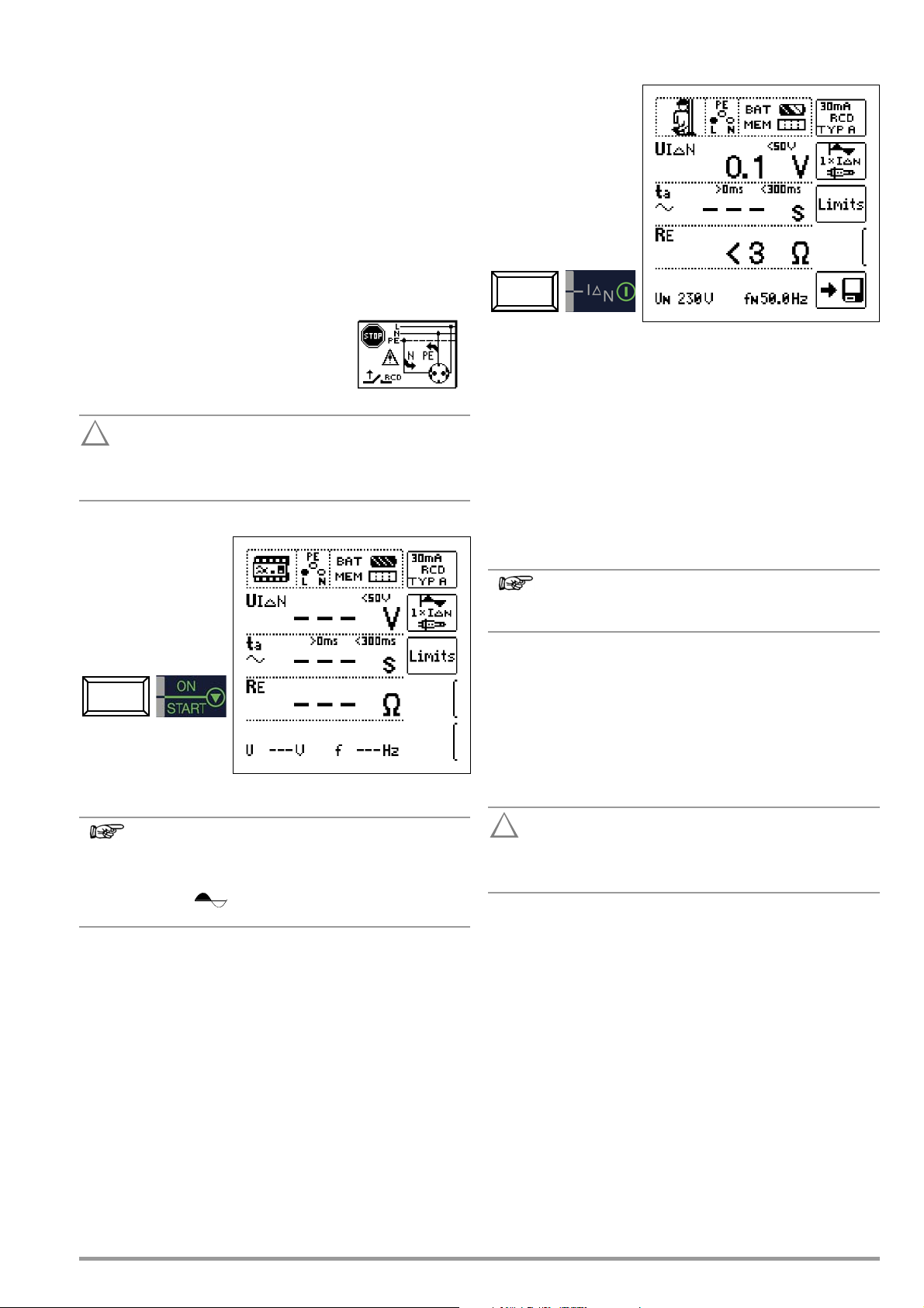
2) Tripping Test after the Measurement of Contact Voltage
➭ Press the
The tripping test need
only be performed at
one measuring point for
each RCCB.
If the RCCB is tripped at nominal residual current,
the MAINS/NETZ LED blinks red (line voltage disconnected) and
time to trip ta and earthing resistance RE appear at the display
panel.
If the RCCB is not tripped at nominal residual current,
the RCD/FI LED lights up red.
I
key.
Δ
N
Execute a data backup before starting measurement and
switch off all consumers in order to prevent the loss of
data in data processing systems.
Start Measurement
Amongst other values, contact voltage U
ing resistance R
appear at the display panel.
E
The measured earthing resistance value RE is acquired
with very little current. More accurate results can be
obtained with the selector switch in the R
The DC + function can be selected here for systems with RCCBs.
and calculated earth-
IΔN
position.
E
Unintentional Tripping of the RCD due to Bias Current within the System
If bias currents should occur, they can be measured with the help
of a current clamp transformer as described in section 13.1 on
page 50. The RCCB may be tripped during the contact voltage
test if extremely large bias currents are present within the system,
or if a test current was selected which is too great for the RCCB.
After contact voltage has been measured, testing can be performed to determine whether or not the RCCB is tripped within
the selected time limits at nominal residual current.
Unintentional Tripping of the RCD due to Leakage Current in the Measuring Circuit
Measurement of contact voltage with 30% nominal residual current does not normally trip an RCCB. However, the trip limit may
be exceeded as a result of leakage current in the measuring circuit, e.g. due to interconnected power consumers with EMC circuit, e.g. frequency converters and PCs.
Contact Voltage Too High
If contact voltage U
nal residual current I
the U
LED lights up red.
L/RL
If contact voltage U
sequence, safety shut-down occurs.
Safety Shut-down: At up to 70 V, a safety shut-down is
tripped within 3 seconds in accordance with IEC 61010.
Contact voltages of up to 70 V are displayed. If contact voltage is
greater than 70 V, U
, which has been measured with 1/3 nomi-
IΔN
and extrapolated to IΔN, is > 50 V (> 25 V),
ΔN
exceeds 50 V (25 V) during the measuring
IΔN
> 70 V is displayed.
IΔN
Limit Values for Allowable, Continuous Contact Voltage
The limit for allowable, continuous contact voltage is UL=50V for
alternating voltages (international agreement). Lower values have
been established for special applications (e.g. medical applications: U
=25V).
L
If contact voltage is too high, or if the RCCB is not
tripped, the system must be repaired (e.g. earthing resistance is too high, defective RCCB etc.)!
3-Phase Connections
For proper RCD testing at three-phase connections, the tripping
test must be conducted for one of the three phase conductors
(L1, L2 and L3).
Inductive Power Consumers
Voltage peaks may occur within the measuring circuit if inductive
consumers are shut down during an RCCB trip test. If this is the
case, the test instrument may display the following message: No
measured value (– – – ). If this message appears, switch all power
consumers off before performing the trip test. In extreme cases,
one of the fuses in the test instrument may blow, and/or the test
instrument may be damaged.
GMC-I Messtechnik GmbH 19
Page 20
7.2 Special Testing for Systems and RCCBs
Note
Attention!
!
I
F
Nominal residual current:
Type 1: RCD, SRCD, PRCD etc.
Nominal current: 6 ... 125 A
Type 2: AC , A/F , B/B+ *
EV/MI
* Type B/B+/EV/MI = AC/DC sensitive
10 ... 500 mA
sine
Negative/positive half-wave
Waveform:
Connection:
without/with probe
System type:
TN/TT, IT
Negative/positive direct current
Contact voltage:
Tripping limit values:
7.2.1 Testing Systems and RCCBs with Rising Residual Current
(AC) for Type AC, A/F, B/B+ and EV/MI RCDs
Measuring Method
The instrument generates a continuously rising residual current of
(0.3 to 1.3) • I
The instrument stores the contact voltage and tripping current
values which were measured at the moment tripping of the RCCB
occurred, and displays them.
One of contact voltage limit values, U
can be selected for measurement with rising residual current.
within the system for the testing of RCDs.
ΔN
=25V or UL=50V/65V,
L
Select Measuring Function
Connection
Start Measurement
Set Parameters for I
Measuring Sequence
After the measuring sequence has been started, the test current
generated by the instrument is continuously increased starting at
0.3 times nominal residual current, until the RCCB is tripped. This
can be observed by viewing gradual filling of the triangle at IΔ.
If contact voltage reaches the selected limit value (U
or 25 V) before the RCCB is tripped, safety shut-down occurs.
The U
F
If the RCCB is not tripped before the rising current reaches nominal residual current I
LED lights up red.
L/RL
Safety Shut-down: At up to 70 V, a safety shut-down is
tripped within 3 seconds in accordance with IEC 61010.
, the RCD/FI LED lights up red.
ΔN
If bias current is present within the system during measurement, it is superimposed onto the residual current
which is generated by the instrument and influences
measured values for contact voltage and tripping current. See also section 7.1.
=65V, 50V
L
Evaluation
According to DIN VDE 0100, Part 600, rising residual current
must, however, be used for measurements in the evaluation of
RCDs, and contact voltage at nominal residual current I
be calculated from the measured values.
The faster, more simple measuring method should thus be taken
advantage of (see sectionl 7.1).
ΔN
must
7.2.2 Testing Systems and RCCBs with Rising Residual Current (AC) for Type B/B+ and EV/MI RCDs (nur MTECH+, MXTRA & SECULIFE IP)
In accordance with VDE 0413, part 6, it must be substantiated
that, with smooth direct current, residual operating current is no
more than twice the value of rated residual current IΔN. A continu-
20 GMC-I Messtechnik GmbH
ously rising direct current, beginning with 0.2 times rated residual
current I
ing current may not exceed twice the value of I
of 5 seconds.
Testing with smoothed direct current must be possible in both
test current directions.
, must be applied to this end. If current rise is linear, ris-
ΔN
within a period
ΔN
Page 21
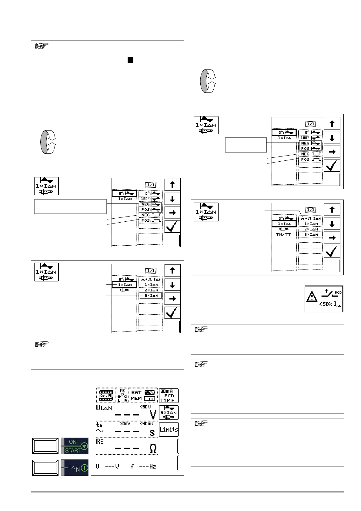
7.2.3 Testing RCCBS with 5 • IΔN
Note
Note
Note
Note
Note
S
I
ΔN
Negative direct current
Positive direct current
Waveform:
180°: Start with neg. half-wave
0°: Start with pos. half-wave
5 times tripping current
X times tripping current:
I
ΔN
Neg. half-wave
Pos. half-wave
Negative direct current
Positive direct current
Waveform:
X times tripping current:
50% IΔN*
* Non-tripping test
with 50% I
ΔN
The measurement of time to trip is performed here with 5 times
nominal residual current.
Measurements performed with 5 times nominal fault current are required for testing type and G RCCBs in the
manufacturing process. They are used for personal
safety as well.
Measurement can be started with the positive half-wave at “0°” or
with the negative half-wave at “180°”.
Both measurements must nevertheless be performed. The longer
of the two tripping times is decisive regarding the condition of the
tested RCCB. Both values must be less than 40 ms.
Select Measuring Function
Set the Parameter – Start with Positive or Negative Half-Wave
7.2.4 Testing of RCCBs which are Suited for Pulsating DC Residual Current
In this case, RCCBs can be tested with either positive or negative
half-waves. The standard calls for tripping at 1.4 times nominal
current.
Select Measuring Function
Set the Parameter – Positive or Negative Half-Wave
Set the Parameter – 5 Times Nominal Current
The following restrictions apply to the selection of tripping
current multiples relative to nominal current:
500 mA: 1 x, 2 x IΔN
Start Measurement
Set the Parameter – Test With and Without “Non-Tripping Test”
Non-Tripping Test
If, during the non-tripping test which lasts for 1
second, the RCD trips too early at 50% I
before the actual tripping test starts, the pop-up
window shown at the right appears.
The following restriction applies to the selection of tripping current multiples relative to nominal current: Double
and five-fold nominal current is not possible in this case.
According to DIN EN 50178 (VDE 160), only type B
RCCBs (AC-DC sensitive) can be used for equipment
with > 4 kVA, which is capable of generating smooth DC
residual current (e.g. frequency converters).
Tests with pulsating DC fault current only are not suitable
for these RCCBs. Testing must also be conducted with
smooth DC residual current in this case.
ΔN
, i.e.
GMC-I Messtechnik GmbH 21
Measurement is performed with positive and negative
half-waves for testing RCCBs during manufacturing. If a
circuit is charged with pulsating direct current, the function of the RCCB can be executed with this test in order
to assure that the RCCB is not saturated by the pulsating
direct current so that it no longer trips.
Page 22
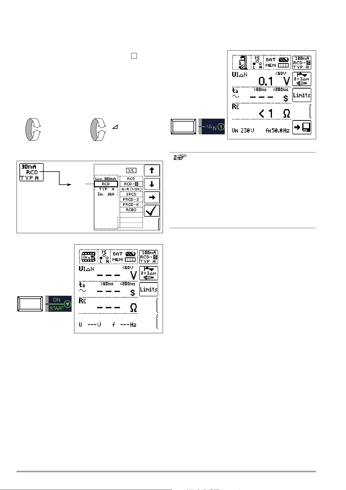
7.3 Testing for Special RCDs
Note
S
I
ΔN
I
F
or
Type 1:
7.3.1 System, Type RCD-S Selective RCCBs
Selective RCDs are used in systems which include two series
connected RCCBs which are not tripped simultaneously in the
event of a fault. These selective RCDs demonstrate delayed
response characteristics and are identified with the symbol.
Measuring Method
The same measuring method is used as for standard RCCBs (see
sections 7.1 on page 18 and 7.2.1 on page 20).
If selective RCDs are used, earthing resistance may not exceed
half of the value for standard RCCBs.
For this reason, the instrument displays twice the measured value
for contact voltage.
Select Measuring Function
Set Parameter – Selective
Tripping Test
➭ Press the IΔN key. The RCCB is tripped. Blinking bars appear
at the display panel, after which time to trip t
sistance R
The tripping test need
only be performed at
one measuring point for
each RCCB.
are displayed.
E
Selective RCDs demonstrate delayed response characteristics. Tripping performance is briefly influenced (up to
30 s) due to pre-loading during measurement of contact
voltage. In order to eliminate pre-charging caused by the
measurement of contact voltage, a waiting period must
be observed prior to the tripping test. After the measuring
sequence has been started (tripping test), blinking bars
are displayed for approximately 30 seconds. Tripping
times of up to 1000 ms are allowable. The tripping test is
executed immediately after once again pressing the I
key.
and earthing re-
A
ΔN
Start Measurement
7.3.2 PRCDs with Non-Linear Type PRCD-K Elements
The PRCD-K is a portable RCD with electronic residual current
evaluation laid out as an in-line device which switches all poles (L,
N and PE). An undervoltage trigger and protective conductor
monitoring are additionally integrated into the PRCD-K.
The PRCD-K is equipped with an undervoltage trigger, for which
reason it has to be operated with line voltage, and measurements
may only be performed in the on state (PRCD-K switches all
poles).
Terminology (from DIN VDE 0661)
Portable protective devices are circuit breakers which can be connected between power consuming devices and permanently
installed electrical outlets by means of standardized plug-andsocket devices.
A reusable, portable protective device is a protective device which
is designed such that it can be connected to movable cables.
Please be aware that a non-linear element is usually integrated
into PRCDs, which leads to immediate exceeding of the greatest
allowable contact voltage during U
than 50 V).
PRCDs which do not include a non-linear element in the protective conductor must be tested in accordance with section 7.3.3
on page 23.
measurements (UIΔ greater
IΔ
Objective (from DIN VDE 0661)
Portable residual current devices (PRCDs) serve to protect persons and property. They allow for the attainment of increased levels of protection as provided by protective measures utilized in
electrical systems for the prevention of electrical shock as defined
in DIN VDE 0100, part 410. They are to be designed such that
they can be installed by means of a plug attached directly to the
protective device, or by means of a plug with a short cable.
22 GMC-I Messtechnik GmbH
Page 23
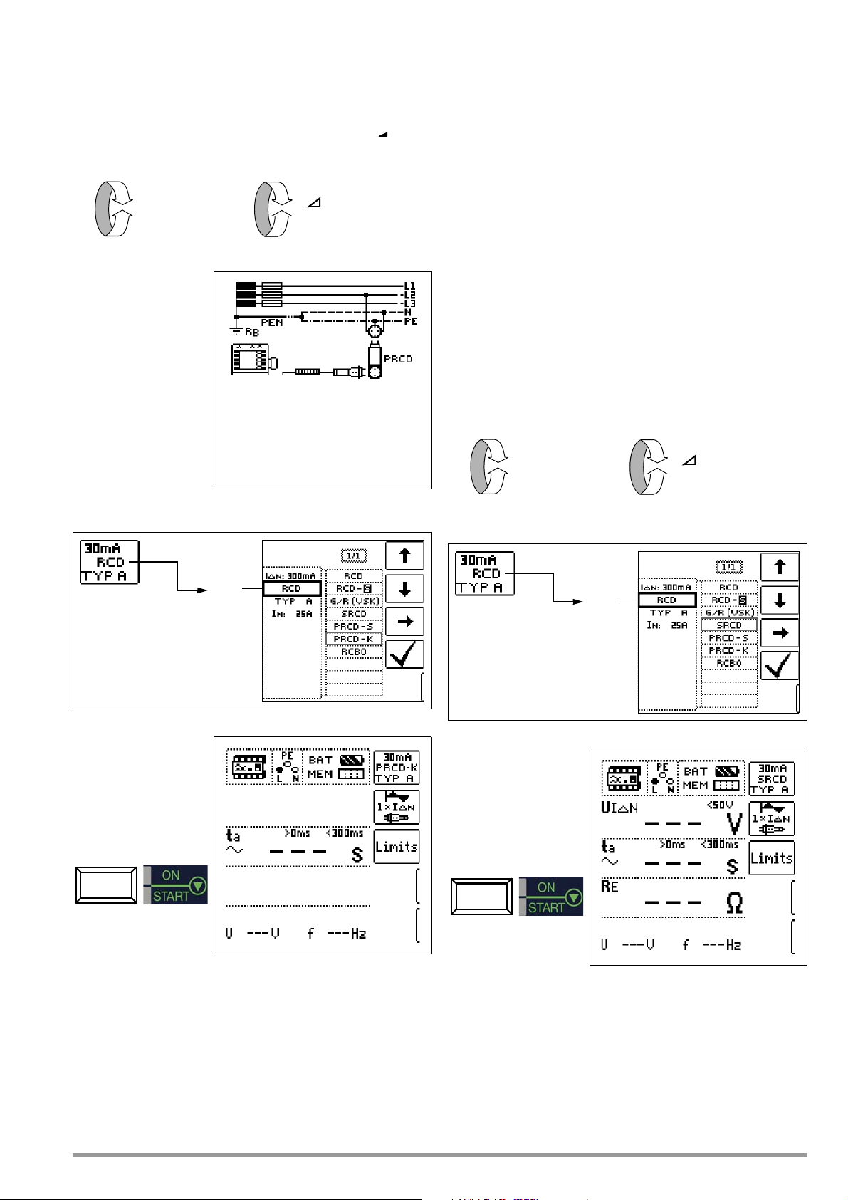
Measuring Method
I
ΔN
I
F
or
Type 1:
I
ΔN
I
F
or
Type 1:
The following can be measured, depending upon the measuring
method:
•Time to trip t
(The PRCD-K must be tripped at 50% nominal current.)
• Tripping current IΔ: testing with rising residual current I
: tripping test with nominal residual current I
A
F
ΔN
Select Measuring Function
7.3.3 SRCD, PRCD-S (SCHUKOMAT, SIDOS or comparable)
RCCBs from the SCHUKOMAT SIDOS series, as well as others
which are of identical electrical design, must be tested after
selecting the corresponding parameter.
Monitoring of the PE conductor is performed for RCDs of this
type. The PE conductor is monitored by the summation current
transformer. If residual current flows from L to PE, tripping current
is cut in half, i.e. the RCCB must be tripped at 50% nominal residual current I
Whether or not PRCDs and selective RCDs are of like design can
be tested by measuring contact voltage U
of greater than 70 V is measured at the PRCD of an other-
U
IΔN
wise error-free system, the PRCD more than likely contains a nonlinear element.
ΔN
.
. If a contact voltage
IΔN
Connection
Set the Parameter – PRCD with Non-Linear Elements
PRCD-S
The PRCD-S (portable residual current device – safety) is a special, portable, protective device with protective conductor detection or protective conductor monitoring. The device serves to protect persons from electrical accidents in the low-voltage range
(130 to 1000 V). The PRCD-S must be suitable for commercial
use, and is installed like an extension cable between an electrical
consumer – as a rule an electrical tool – and the electrical outlet.
Select Measuring Function
Set Parameter – SRCD / PRCD
Start Measurement
Start Measurement
GMC-I Messtechnik GmbH 23
Page 24
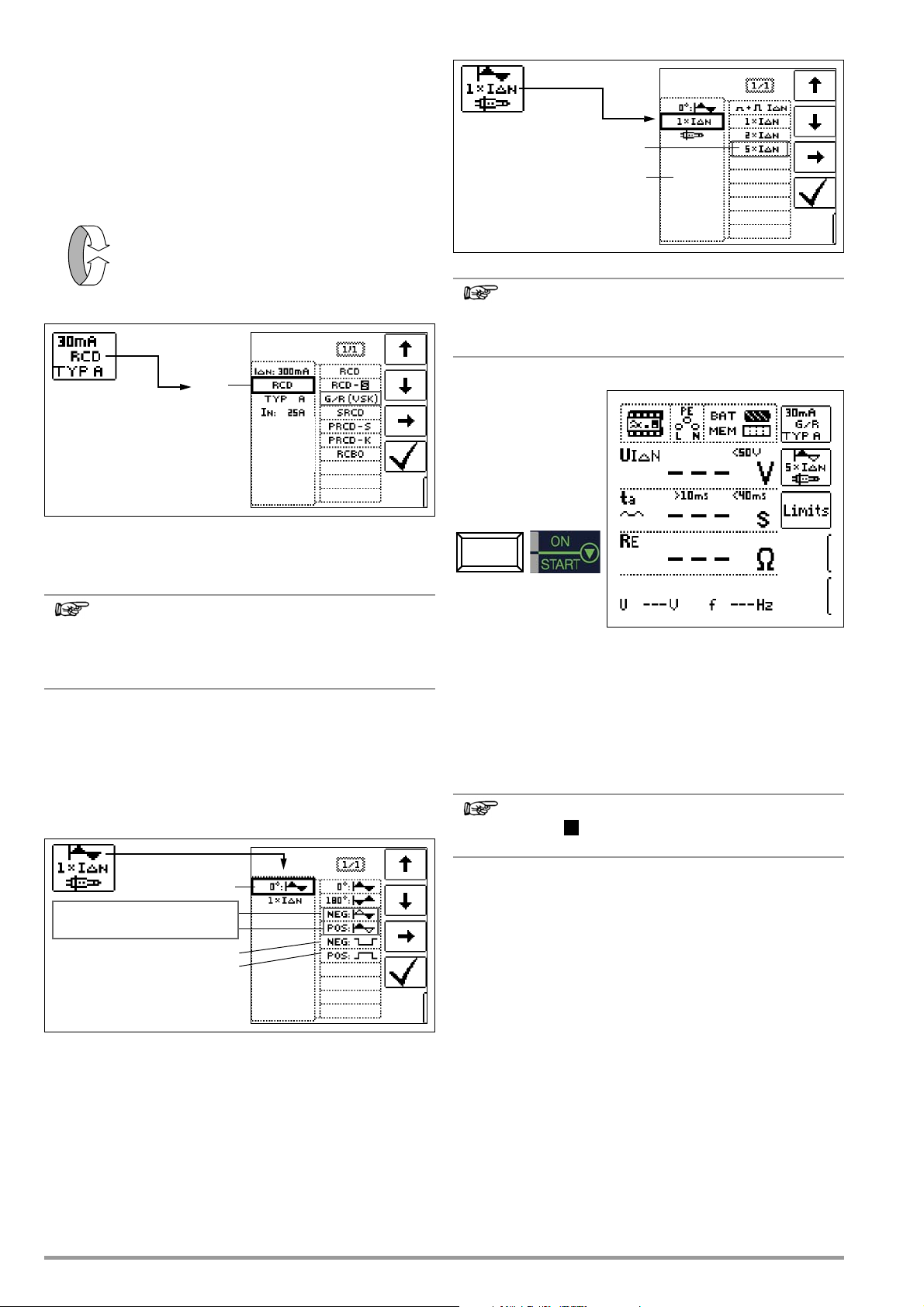
7.3.4 Type G or R RCCB
Note
Note
Note
I
ΔN
Type 1:
180°: Start with neg. half-wave
0°: Start with pos. half-wave
Waveform:
Negative direct current
Positive direct current
X times tripping current:
5 times tripping current
S
In addition to standard RCCBs and selective RCDs, the special
characteristics of the type G RCCB can also be tested with the
test instrument.
The type G RCCB is an Austrian specialty and complies with the
ÖVE/ÖNORM E 8601 device standard. Erroneous tripping is minimized thanks to its greater current carrying capacity and shortterm delay.
Select Measuring Function
Set the Parameter – 5 Times Nominal Current
Set Parameter – Type G/R (VSK)
Contact voltage and time to trip can be measured in the G/RRCD switch position.
It must be observed that time to trip for type G RCCBs
may be as long as 1000 ms when measurement is made
at nominal residual current. Set the limit value correspondingly.
➭ Then select 5 x I
for the G/R setting) and repeat the tripping test beginning with
the positive half-wave at 0° and the negative half-wave at
180°. The longer of the two tripping times is decisive regarding the condition of the tested RCCB.
in the menu (this is selected automatically
ΔN
The following restrictions apply to the selection of
tripping current multiples relative to nominal current:
500 mA: 1 x, 2 x IΔN
Start Measurement
In both cases, tripping time must be between 10 ms (minimum
delay time for type G RCCBs!) and 40 ms.
Type G RCCBs with other nominal residual current values must
be tested with the corresponding parameter setting under menu
item I
adjusted.
. In this case as well, the limit value must be appropriately
ΔN
Set the Parameter – Start with Positive or Negative Half-Wave
24 GMC-I Messtechnik GmbH
The RCD parameter setting for selective RCCBs is not
suitable for type G RCCBs.
Page 25
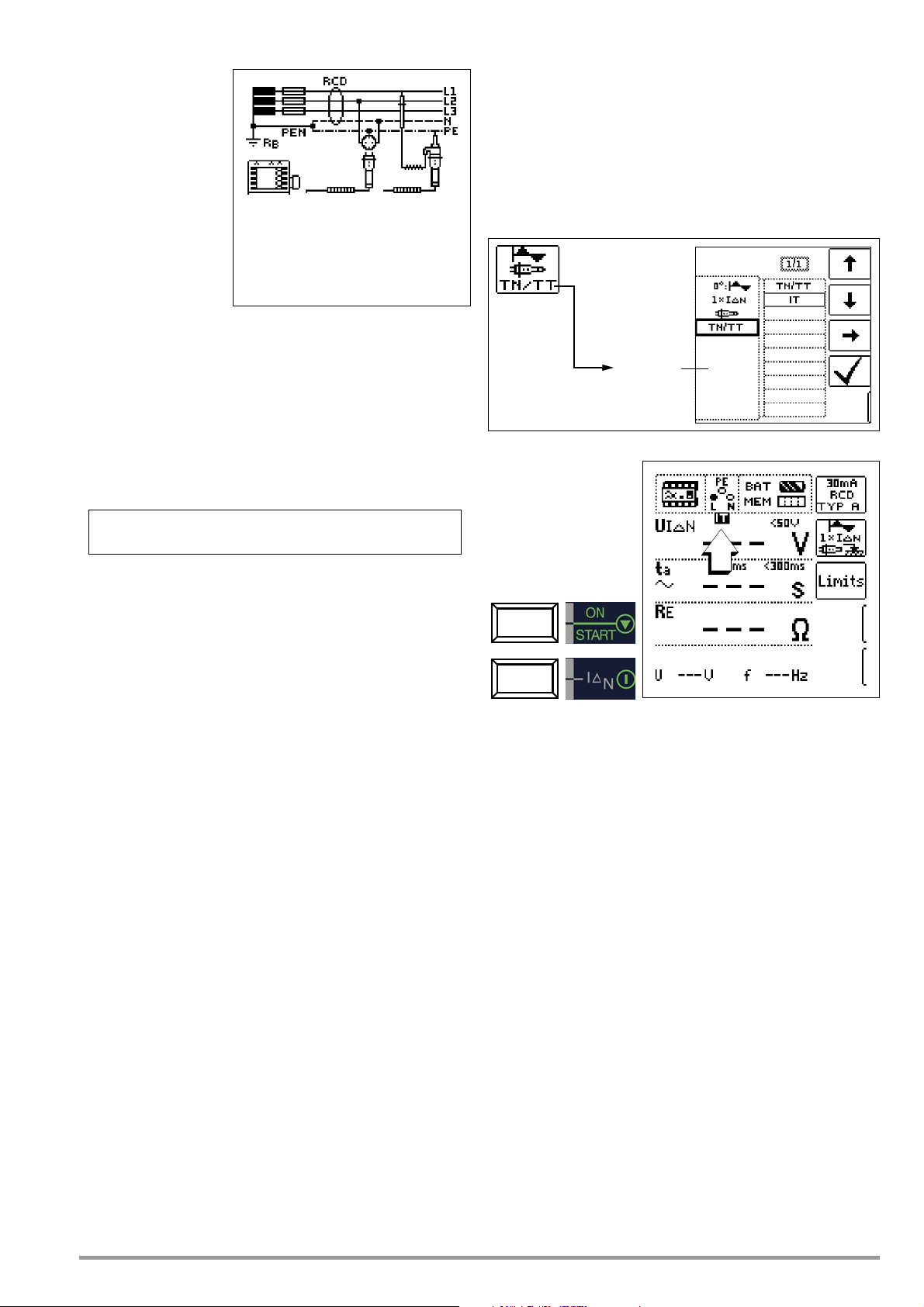
7.4 Testing Residual Current Circuit Breakers in TN-S Systems
UIΔNR
E
IΔN• 1Ω 30mA⋅ 30m V 0
·
03V,== ==
System
type:
Connection
RCCBs can only be used in TN-S systems. An RCCB would not
work in a TN-C system because PE is directly connected to the
neutral conductor in the outlet (it does not bypass the RCCB).
This means that residual current would be returned via the RCCB
and would not generate any differential current, which is required
in order to trip the RCCB.
As a rule, the display for contact voltage is also 0.1 V, because
the nominal residual current of 30 mA together with minimal loop
resistance results in a very small voltage value:
7.5 Testing of RCD Protection in IT Systems with High Cable Capacitance (e.g. in Norway)
The desired system type (TN/TT oder IT) can be selected for RCD
test type U
A probe is absolutely essential for measurement in IT systems,
because contact voltage U
cannot otherwise be measured.
After selecting the IT system setting, connection with probe is
selected automatically.
(IΔN, ta), and for earthing measurement (RE).
IΔN
which occurs in these systems
IΔN
Set the Parameter – Select System Type
Start Measurement
GMC-I Messtechnik GmbH 25
Page 26
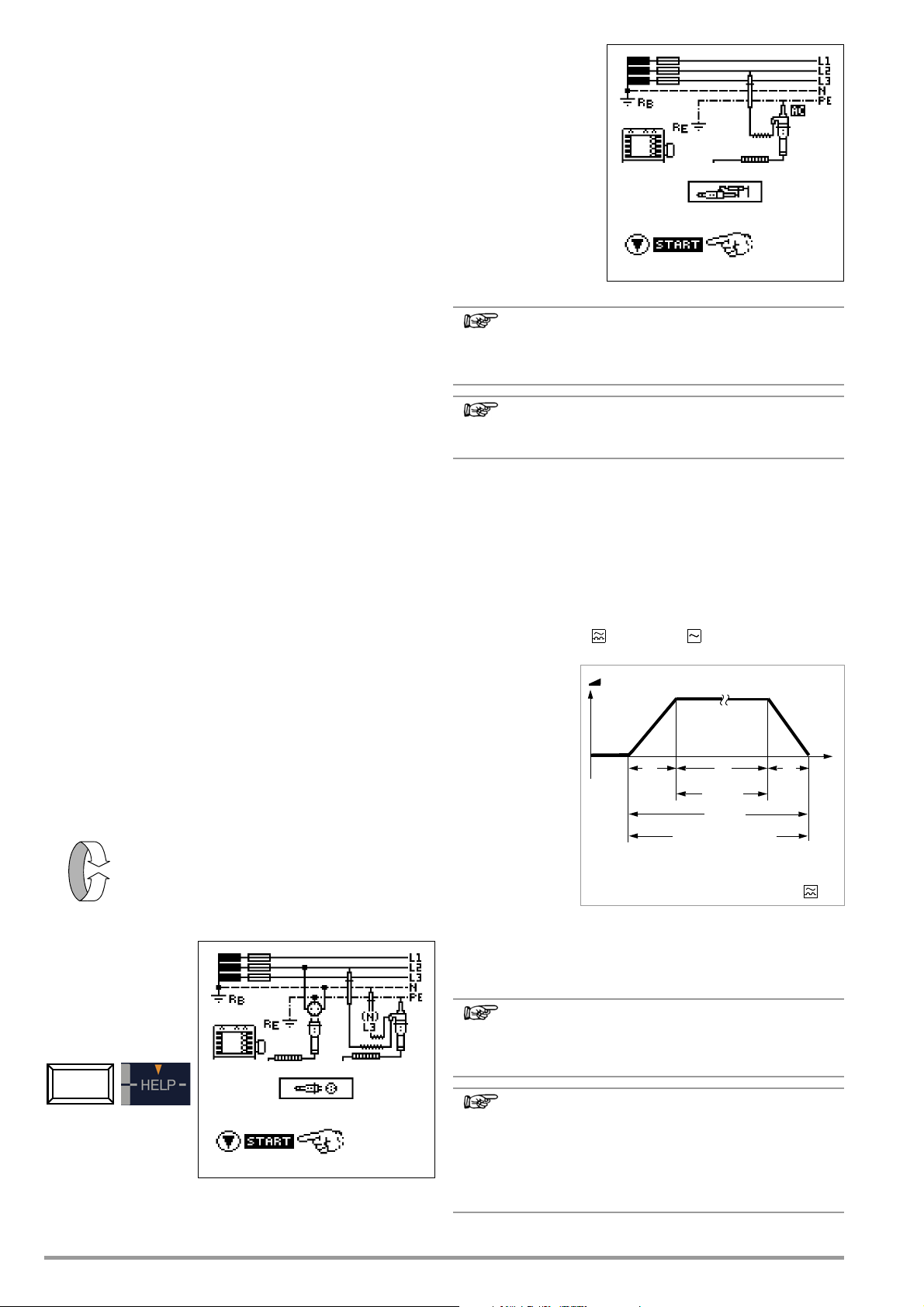
8 Testing of Breaking Requirements
Note
Note
Note
Note
Z
L-PE
Start
t1 t3
Measurement
t2
Operation
RCD Disabled!
t
I
F
/mA
Suppression of RCCB tripping for RCCBs
which are sensitive to pulsating current
Overcurrent Protective Devices,
Measurement of Loop Impedance and
Determination of Short-Circuit Current
(functions Z
Testing of overcurrent protective devices includes visual inspection and measurement. Use the PROFITEST MASTER or SECULIFE IP
to perform measurements.
Measuring Method
Loop impedance Z
ascertained in order to determine if the breaking requirements for
protective devices have been fulfilled.
Loop impedance is the resistance within the current loop (utility
station – phase conductor – protective conductor) when a shortcircuit to an exposed conductive part occurs (conductive connection between phase conductor and protective conductor). Shortcircuit current magnitude is determined by the loop impedance
value. Short-circuit current I
value set forth by DIN VDE 0100, so that reliable breaking of the
protective device (fuse, automatic circuit breaker) is assured.
Thus the measured loop impedance value must be less than the
maximum allowable value.
Tables containing allowable display values for loop impedance
and minimum short-circuit current display values for ampere ratings for various fuses and circuit breakers can be found in the
help texts and in section 21 beginning of page 88. Maximum
device error in accordance with VDE 0413 has been taken into
consideration in these tables. See also section 8.2.
In order to measure loop impedance Z
test current of 3.7 to 7 A (60 to 550 V) depending on line voltage
and line frequency. At 16 Hz, the test has a duration of no more
than 1200 ms.
If dangerous contact voltage occurs during measurement
(> 50 V), safety shut-down occurs.
The test instrument calculates short-circuit current IK based on
measured loop impedance
current calculation is made with reference to nominal line voltage
for line voltages which lie within the nominal ranges for 120 V,
230 V and 400 V systems. If line voltage does not lie within these
nominal ranges, the instrument calculates short-circuit current IK
based on prevailing line voltage and measured loop impedance
Z
.
L-PE
Select Measuring Function
Connection:
Schuko / 3-Pole Adapter
and IK)
L-P E
is measured and short-circuit current IK is
L-P E
may not fall below a predetermined
K
, the instrument uses a
L-P E
Z
and line voltage. Short-circuit
L-P E
Connection:
2-Pole Adapter
Loop impedance should be measured for each electrical
circuit at the farthest point, in order to ascertain maximum loop impedance for the system.
Observe national regulations, e.g. the necessity of conducting measurements without regard for RCCBs in Austria.
3-Phase Connections
Measurement of loop impedance to earth must be performed at
all three phase conductors (L1, L2, and L3) for the testing of overcurrent protective devices at three phase outlets.
8.1 Measurements with Suppression of RCD Tripping
Measuring Method with Suppression of RCD Tripping
The test instruments PROFITEST MTECH+, PROFITEST MXTRA and
SECULIFE IP make it possible to measure loop impedance in TN
systems with type A, F
300, 500 mA nominal residual current).
The test instrument
generates a direct
current to this end,
which saturates the
RCCB’s magnetic
circuit.
The test instrument
then superimposes
a measuring current which only
demonstrates halfwaves of like polarity. The RCCB is no
longer capable of
detecting this measuring current, and
is consequently not tripped during measurement.
A four conductor measuring cable is used between the instrument and the test plug. Cable and measuring adapter resistance
is automatically compensated for during measurement and does
not effect measurement results.
and type AC RCCBs (10, 30, 100,
A loop impedance measurement by using the method of
suppression of RCD tripping can only be performed with
26 GMC-I Messtechnik GmbH
type A and F RCDs.
Bias Magnetization
Only AC measurements can be performed with the 2pole adapter. Suppression of RCD tripping by means of
bias magnetization with direct current is only possible via
a country-specific plug insert, e.g. SCHUKO, or the 3pole adapter (neutral conductor necessary).
Page 27
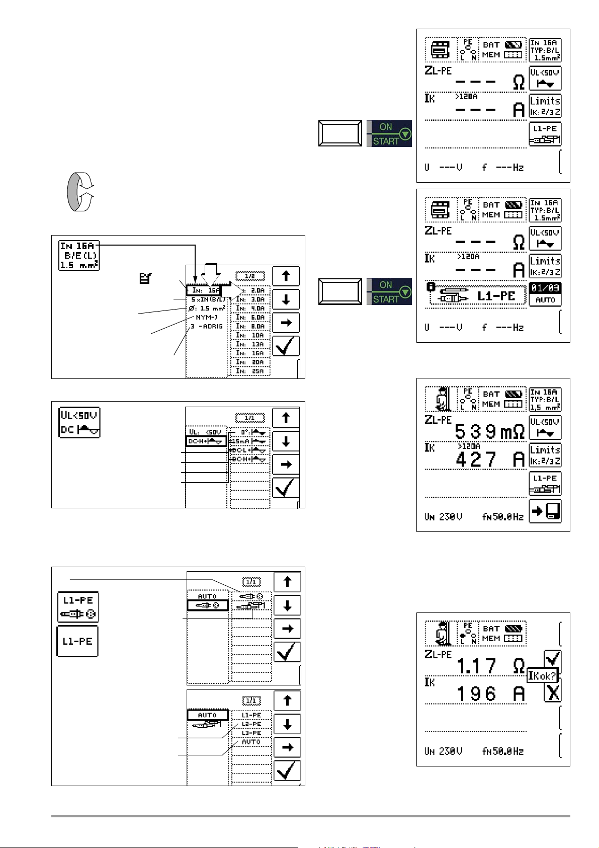
8.1.1 Measurement with Positive Half-Waves
Z
L-PE
Tripping characteristics:
Diameter*: 1.5 to 70 sq. mm
Cable types*: NY...- H07...
Number of wires*: 2 to 10-strand
Nominal current:
2 ... 160 A, 9999 A
A, B/L, C/G, D, E, H, K, GL/GG & Factor
Sine
15 mA sinusoidal
Waveform:
DC-L offset and positive half-wave
Contact voltage:
DC-H offset and positive half-wave
2-pole
Measurement with country-specific
plug insert (e.g. Schuko)
Note
Selecting test probe and Lx-PE
reference or AUTO is only relevant for
report generation.
Semiautomatic measurement
See also section 5.8 regarding the
AUTO parameter.
Polarity selection
measurement
(only MTECH+/MXTRA/SECULIFE IP)
Measurement by means of half-waves plus direct current makes it
possible to measure loop impedance in systems which are
equipped with RCCBs.
For DC measurement with half-waves you can choose between
two alternatives:
DC-L: lower premagnetization current allowing for faster mea-
surement
DC-H: higher premagnetization current, therefore higher protec-
tion against tripping of RCD
Select Measuring Function
Set Parameters
Start Measurement
Semiautomatic
Measurement
* Parameters used for report generation only which do not influence the measurement
Sine (full wave) Setting for electric circuits without RCD
15 mA sinusoidal Setting only for motor protection switch
DC+half-wave Setting for electric circuits with RCD
GMC-I Messtechnik GmbH 27
with low nominal current
8.2 Evaluation of Measured Values
The maximum allowable
loop impedance Z
which may be displayed
after allowance has
been made for maximum operating measurement error (under
normal measuring conditions) can be determined with the help of
Table 1 on page 88.
Intermediate values can
be interpolated.
The maximum allowable
nominal current for the
protective device (fuse
or circuit breaker) for a line voltage of 230 V after allowance has
been made for maximum measuring error can be determined with
the help of Table 6 on page 89 based upon measured short-circuit current (corresponds to DIN VDE 0100 Part 600).
L-P E
Special Case: Suppressing Display of the Limit Value
The limit value cannot be
ascertained. The inspector is prompted to evaluate the measured values himself, and to
acknowledge or reject
them with the help of the
softkeys.
Measurement passed:
key
✔
Measurement failed:
X key
Page 28
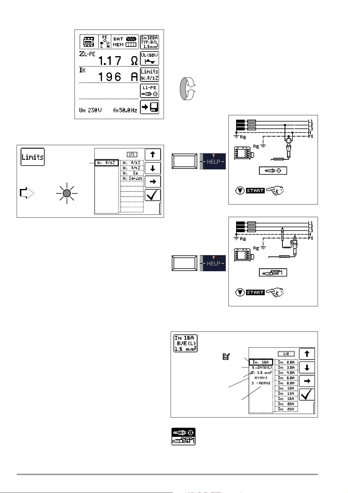
The measured value can only be saved after it has been evalu-
Limit value:
I
K
< limit value
UL ⏐ R
L
Z
L-N
Nominal current:
Diameter: 1.5 to 70 sq. mm
Cable types: NY..., H03... - H07...
Number of wires: 2 ... 10-strand
2 ... 160 A, 9999 A
Tripping characteristics:
A, B/L, C/G, D, E, H, K, GL/GG & Factor
ated.
9 Measuring Line Impedance (Z
function)
L-N
Measuring Method (internal line resistance measurement)
Supply impedance Z
method used for loop impedance Z
26). However, the current loop is completed via neutral conductor
N rather than protective conductor PE as is the case with loop
impedance measurement.
is measured by means of the same
L-N
(see section 8 on page
L-P E
Select Measuring Function
Connection:
Schuko
8.3 Settings for Short-circuit current Calculation – Parameter I
K
Short-circuit current IK is used to test shutdown by means of an
overcurrent protective device. In order for an overcurrent protective device to be tripped on time, short-circuit current IK must be
greater than tripping current Ia (see table 6 in section 21.1). The
variants which can be selected with the “Limits” key have the following meanings:
I
: Ia The measured value displayed for IK is used without
K
I
: Ia+Δ% The measured value displayed for Z
K
any correction to calculate Z
by an amount equal to the test instrument’s measuring
L-PE
.
L-P E
is corrected
uncertainty in order to calculate IK.
I
: 2/3 Z In order to calculate IK, the measured value displayed
K
I
: 3/4 Z Z
K
I
K
for Z
all possible deviations (these are defined in detail by
VDE 0100, part 600, as Z
is corrected by an amount corresponding to
L-P E
≤ 2/3 x U0/Ia).
≤ 3/4 x U0/Ia
s(m)
s(m)
Short-circuit current calculated by the instrument (at nominal
voltage)
Z Fault loop impedance
Ia Tripping current
(see data sheets for circuit breakers / fuses)
Δ%Test instrument intrinsic error
Connection:
2-Pole Adapter
Set Parameters
Special Case Ik > I
28 GMC-I Messtechnik GmbH
see page 29.
kmax
Press the softkey shown at the left in order to switch
back and forth between the country-specific plug
insert, e.g. SCHUKO, and 2-pole adapter. The
selected connection type is displayed inversely
(white on black).
Page 29
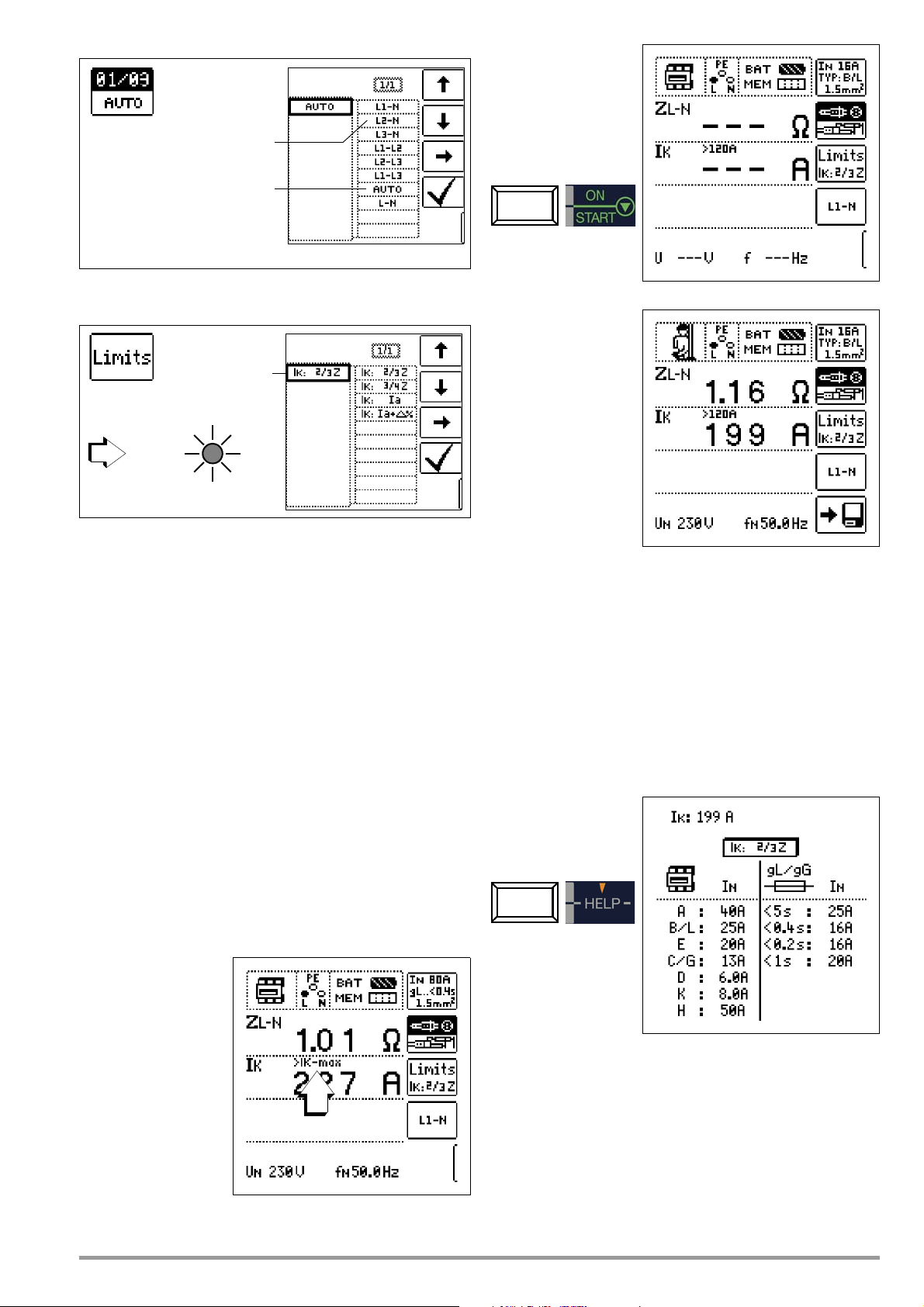
Start Measurement
Semiautomatic measurement
See also section 5.8 regarding the
AUTO parameter. L-PE relationships are
not possible here. The neutral L-N relationship is not offered during automatic
sequencing to the right of the auto entry!
Polarity selection
Limit value:
I
K
< limit value
UL ⏐ R
L
I
K
Settings for Short-circuit current Calculation – Parameter I
K
Short-circuit current IK is used to test shutdown by means of an
overcurrent protective device. In order for an overcurrent protective device to be tripped on time, short-circuit current IK must be
greater than tripping current Ia (see table 6 in section 21.1). The
variants which can be selected with the “Limits” key have the following meanings:
I
: Ia The measured value displayed for IK is used without
K
I
: Ia+Δ% The measured value displayed for Z
K
any correction to calculate Z
by an amount equal to the test instrument’s measuring
L-PE
.
L-P E
is corrected
uncertainty in order to calculate IK.
I
: 2/3 Z In order to calculate IK, the measured value displayed
K
I
: 3/4 Z Z
K
for Z
all possible deviations (these are defined in detail by
VDE 0100, part 600, as Z
is corrected by an amount corresponding to
L-P E
≤ 2/3 x U0/Ia).
≤ 3/4 x U0/Ia
s(m)
s(m)
Display of U
(UN / fN)
L-N
If the measured voltage value lies within a range of ±10% of the
respective nominal line voltage of 120 V, 230 V or 400 V, the
respectively corresponding nominal line voltage is displayed. In
the case of measured values outside of the ±10% tolerance, the
actual measured value is displayed.
Displaying the Fuse Table
After measurement has been performed, allowable fuse types can
be displayed by pressing the HELP key.
The table shows maximum allowable nominal current dependent
upon fuse type and breaking requirements.
Short-circuit current calculated by the instrument (at nominal
I
K
voltage)
Z Fault loop impedance
Ia Tripping current (see data sheet for circuit breakers / fuses)
Δ%Test instrument inherent error
Special case Ik > I
If the value for the shortcircuit current is beyond
the measured values
defined in
PROFITEST MASTER, it is
indicated by > IK-max“.
In this case, it will be
necessary to evaluate
the measuring result
manually.
GMC-I Messtechnik GmbH 29
kmax
Key: Ia = breaking current, I
I
= nominal current, tA = tripping time
N
= short-circuit current,
K
Page 30

10 Earthing Resistance Measurement (RE function)
Note
Attention!
!
Note
Start
t1
t3
Measurement
t2
RCD Disabled!
t
I
F
/mA
Suppression of RCCB tripping for RCCBs which
are sensitive to pulsating current
Operation
Earthing resistance RE is important for automatic shutdown in
system segments. It must have a low value in order to assure that
high short-circuit current flows and the system is shut down reliably by the RCCB in the event of a fault.
Test S e t up
Earthing resistance (RE) is the sum of the earth electrode’s dissipation resistance and earth conductor resistance. Earthing resistance is measured by applying an alternating current via the earth
conductor, the earth electrode and earth electrode resistance.
This current, as well as voltage between the earth electrode and a
probe, are measured.
The probe is connected to the probe connector socket (17) with a
4 mm contact protected plug.
Direct Measurement with Probe (mains powered measurement)
Direct measurement of earthing resistance RE is only possible
within a measuring circuit which includes a probe. However, this
means that the probe and reference earth must be of like potential, i.e. that they are positioned outside of the potential gradient
area. The distance between the earth electrode and the probe
should be at least 20 m.
Measurement without Probe (mains powered measurement)
In many cases, especially in extremely built-up areas, it is difficult,
or even impossible, to set a measuring probe. In such cases,
earthing resistance can be measured without a probe. In this
case, however, the resistance values for the operational earth
electrode R
measurement results.
Measuring Method (w. probe) (mains powered measurement)
The instrument measures earthing resistance RE by means of the
ammeter-voltmeter test.
Resistance RE is calculated from the quotient of voltage UE and
current I
The test current which is applied to earthing resistance is controlled by the instrument (see section 19, “Characteristic Values”,
beginning on page 82 for pertinent values).
A voltage drop is generated which is proportional to earthing
resistance.
and phase conductor L are also included in the
B
where UE is between the earth electrode and the probe.
E
Measurement with or without earth electrode voltage depending
upon entered parameters and the selected type of connection:
RANGE Connection Measuring Functions
xx Ω / xx kΩ
10 Ω / U
xx Ω / xx kΩ *
* This parameter results in automatic selection of probe connection.
*
E
No probe measurement
No U
measurement
E
Probe measurement activated
U
is measured
E
Probe measurement activated
measurement
No U
E
Clamp measurement activated
measurement
No U
E
Measuring Method with Suppression of RCD Tripping
(mains powered earthing measurement)
The test instruments PROFITEST MTECH+, PROFITEST MXTRA and
SECULIFE IP make it possible to measure loop impedance in TN
systems with type A, F and type AC RCCBs (10, 30, 100,
300, 500 mA nominal residual current).
The test instrument
generates a direct
current to this end,
which saturates the
RCCB’s magnetic
circuit.
The test instrument
then superimposes
a measuring current
which only demonstrates half-waves
of like polarity. The
RCCB is no longer
capable of detecting this measuring
current, and is consequently not tripped during measurement.
A four conductor measuring cable is used between the instrument and the test plug. Cable and measuring adapter resistance
is automatically compensated for during measurement and does
not effect measurement results.
Measurement cable and measuring adapter resistance
are compensated for automatically during measurement
and have no effect on measurement results.
If dangerous contact voltages occur during measurement
(> 50 V), the measurement is interrupted and safety shutdown occurs.
Probe resistance does not effect measurement results
and may be as high as 50 kΩ.
The probe is part of the measuring circuit and may carry
a current of up to 3.5 mA in accordance with VDE 0413.
Bias Magnetization
Only AC measurements can be performed with the 2pole adapter. Suppression of RCD tripping by means of
bias magnetization with direct current is only possible via
a country-specific plug insert, e.g. SCHUKO, or the 3pole adapter (neutral conductor necessary).
Limit Values
Earthing resistance (earth coupling resistance) is determined primarily by the electrode’s contact surface and the conductivity of
the surrounding earth.
The specified limit value depends on the type of electrical system
and its shutdown conditions in consideration of maximum contact
voltage.
Evaluation of Measured Values
The maximum allowable displayed resistance values which assure
that the required earthing resistance is not exceeded, and for
which maximum device operating error has already been taken
into consideration (at nominal conditions of use), can be determined with the help of Table 2 on page 88. Intermediate values
can be interpolated.
30 GMC-I Messtechnik GmbH
Page 31

10.1 Earthing Resistance Measurement – Mains Operated
Note
RER
E
The following types of measurement or connection are possible:
• 2-pole measurement via 2-pole adapter
• 2-pole measurement via earthing contact plug
(not possible in IT systems)
• 3-pole measurement via 2-pole adapter and
probe
• Selective measurement: 2-pole measurement
with probe and current clamp sensor
At left in figure:
2-pole measuring
adapter for contacting PE and L
measuring points
At right in figure:
The PRO-Schuko
measuring
adapter can be
used as an alternative.
Select Measuring Function
10.2 Earthing Resistance Measurement – Battery Powered (only MPRO & MXTRA)
The 5 following types of measurement or connection are possible:
• 3-Pole measurement via PRO-RE adapter
• 4-Pole measurement via PRO-RE adapter
• Selective measurement with clamp meter
(4-pole) via PRO-RE adapter
• 2-clamp measurement via PRO-RE/2 adapter
• Measurement of soil resistivity
via PRO-RE adapter
Figure at right:
PRO-RE adapter for connect-
ing earth electrode, auxiliary
earth electrode, probe and
auxiliary probe to the test
instrument for
3/4-pole measurement,
selective measurement and
measurement of soil resistivity
ρ
E
Select Operating Mode
The selected operating mode is displayed inversely:
mains~ in white against a black background.
Battery powered measurement is not possible:
The error message shown at the left appears
if the selected connection type is inappropriate for the operating mode.
Special Case: Manual Measuring Range Selection (test current
selection)
(R ≠ AUTO, R = 10 kΩ (4 mA), 1 kΩ (40 mA), 100 Ω (0.4 A),
10 Ω (3.7 ... 7 A), 10 Ω/U
When the measuring range is selected manually, accuracy values are only valid starting at 5% of the upper limit range value
(except for the 10Ω
)
E
range; separate display for small values).
Set Parameters
❑ Measuring range: AUTO, 10 kΩ (4 mA), 1 kΩ (40 mA), 100 Ω
(0.4 A), 10 Ω (> 3.7 A)
In systems with RCCBs, resistance or test current must be selected such that it is less than tripping current (½ I
❑ Contact voltage: UL < 25 V, < 50 V, < 65 V, see section 5.7 re-
garding freely selectable voltage.
❑ Transformer ratio: depends on utilized current clamp sensor
❑ Connection type: 2-pole adapter, 2-pole adapter + probe,
2-pole adapter + clamp meter
❑ Type of system: TN or TT
❑ Test current waveform
See section 10.4 through section 10.6 regarding advisable parameters for the respective measurement and connection types.
ΔN
).
Perform Measurements
See section 10.4 through section 10.6.
Figure at right:
PRO-RE/2 measuring adapter as
accessory for connecting the EClip 2 generator clamp for 2-clamp
measurement and earth loop resistance measurement.
Select Measuring Function
Select Operating Mode
The selected operating mode is displayed inversely:
white battery icon against black background.
Mains powered measurement is not possible:
The error message shown at the left appears
if the selected connection type is inappropriate for the operating mode.
Set Parameters
❑ Measuring range: AUTO, 50 kΩ, 20 kΩ, 2 kΩ, 200 Ω, 20 Ω
❑ Current clamp sensor transformer ratio:
1:1 (1 V/A,) 1:10 (100 mV/A), 1:100 (10 mV/A), 1:1000 (1 mV/A)
❑ Connection type: 3-pole, 4-pole, selective, 2-clamp, ρ
❑ Distance d (for measuring
See section 10.7 through section 10.11 regarding advisable
parameters for the respective measurement and connection
types.
ρ
E
): xx m
(Rho)
E
Perform Measurements
See section 10.7 through section 10.11.
GMC-I Messtechnik GmbH 31
Page 32

10.3
P
R
O
F
I
T
E
S
T
Ri
W
a
t
e
r
P
i
p
e
E
2
E
1
B
R
E
Limit value:
RE > Limit Value
UL ⏐ R
L
Earthing Resistance, Mains Powered – 2-Pole Measurement with 2-Pole Adapter or Country-Specific Plug (Schuko) without Probe
Key
R
Operational earth
B
R
Earthing resistance
E
R
Internal resistance
i
R
Earthing resistance through equipotential bonding
X
systems
R
Probe resistance
S
PAS Equipotential bonding busbar
RE Overall earthing resistance (R
//RE2//water pipe)
E1
In the event that it is impossible to set a probe, earthing resistance can be estimated by means of an “earth loop resistance
measurement” without probe.
The measurement is performed exactly as described in section 10.4,
“Earthing Resistance Measurement, Mains Powered – 3-Pole Measurement: 2-Pole Adapter with Probe”, beginning on page 33. However, no probe is connected to the probe connector socket (17).
The resistance value R
also includes operational earth electrode resistance R
tance at phase conductor L. These values must be deducted from
obtained with this measuring method
ELoop
B
and resis-
the measured value in order to determine earthing resistance.
If conductors of equal cross section are assumed (phase conductor L
and neutral conductor N), phase conductor resistance is half as great
as supply impedance Z
Supply impedance can be measured as described in section 9
(phase conductor + neutral conductor).
L-N
beginning of page 28. In accordance with DIN VDE 0100, operational
earth electrode R
1) Measurement: ZLN amounts to Ri = 2 · R
2) Measurement: Z
3) Calculation:
must lie within a range of “0Ω to 2Ω”.
B
amounts to R
L-P E
RE1 amounts to Z
L-P E
ELoop
– 1/2 · Z
L
L-N
; where RB = 0
The value for operational earth conductor resistance RB should be
ignored in the calculation of earthing resistance, because it is
generally unknown.
The calculated earthing resistance thus includes operational earth
conductor resistance as a safety factor.
In parameter setting steps 1 to 3 are performed automatically by the test instrument.
Select Measuring Function
Set Parameters
❑ Measuring range: AUTO, 10 kΩ (4 mA), 1 kΩ (40 mA), 100 Ω
(0.4 A), 10 Ω (3.7 ... 7 A). In systems with RCCBs, resistance
or test current must be selected such that it is less than tripping current (½ I
ΔN
).
❑ Connection type: 2-pole adapter
❑ Contact voltage: UL < 25 V, < 50 V, < 65 V
❑ Test current waveshape: Sinusoidal (full-wave), 15 mA sinusoidal
(full-wave), DC offset and positive half-wave
❑ System type: TN/TT, IT
❑ Transformer ratio: irrelevant in this case
Start Measurement
Select Operating Mode
32 GMC-I Messtechnik GmbH
Page 33

10.4 Earthing Resistance Measurement, Mains Powered – 3-Pole Measurement: 2-Pole Adapter with Probe
Note
P
R
O
F
I
T
E
S
T
W
a
t
e
r
P
i
p
e
SE
2
E
1
B
R
E1
U
Probe
I
--------------=
R
E
Limit value:
RE > Limit Value
UL ⏐ R
L
Key
R
Operational earth electrode
B
R
Earthing resistance
E
R
Earthing resistance through equipotential bonding sys-
X
tems
R
Probe resistance
S
PAS Equipotential bonding busbar
RE Overall earthing resistance (R
Measurement of R
E
//RE2//water pipe)
E1
Select Measuring Function
Select Operating Mode
Set Parameters
❑ Measuring range: AUTO,
10 kΩ (4 mA), 1 kΩ (40 mA), 100 Ω (0.4 A), 10 Ω (3.7 ... 7 A)
In systems with RCCBs, resistance or test current must be selected such that it is less than tripping current (½ I
❑ Connection type: 2-pole adapter + probe
❑ Contact voltage: UL < 25 V, < 50 V, < 65 V, see section 5.7 re-
garding freely selectable voltage.
❑ Test current waveshape:
Sinusoidal (full-wave), 15 mA sinusoidal (full-wave),
DC offset and positive half-wave
❑ System type: TN/TT, IT
❑ Transformer ratio: irrelevant in this case
ΔN
).
Connection
2-pole adapter and probe are connected
GMC-I Messtechnik GmbH 33
Start Measurement
The following diagram appears if the
2-pole adapter is connected incorrectly.
Page 34

10.5 Earthing Resistance Measurement, Mains Powered – Measurement of Earth Electrode Voltage (UE function)
Note
P
R
O
F
I
T
E
S
T
Ri
W
a
t
e
r
P
i
p
e
SE
2
E
1
B
U
E
UNR
E
⋅
R
E
Loop
-------------------=
R
E
Limit value:
RE > Limit Value
UL ⏐ R
L
This measurement is only possible with a probe (see section
10.4). Earth electrode potential U
the earth electrode between the earth electrode terminal and ref-
is the voltage which occurs at
E
erence earth if a short-circuit occurs between the phase conductor and the earth electrode. Measurement of earth electrode
potential is required by Swiss standard NIV/NIN SEV 1000.
Measuring Method
In order to determine earth electrode potential, the instrument first
measures earth electrode loop resistance R
ately thereafter earthing resistance R
values and then calculates earth electrode potential with the fol-
. The instrument stores both
E
, and immedi-
ELoop
lowing equation:
The calculated value is displayed at the display panel.
Select Measuring Function
Select Operating Mode Select measuring range
Set Parameters
❑ Measuring range: 10 Ω / U
❑ Connection type: 2-pole adapter + probe
❑ Contact voltage: UL < 25 V, < 50 V, < 65 V, see section 5.7 re-
garding freely selectable voltage.
❑ Test current waveshape: sinusoidal only in this case (full-wave)!
❑ System type: TN/TT, IT
❑ Transformer ratio: irrelevant in this case
E
Start Measurement
Connection
The following diagram appears if the
2-pole adapter is connected incorrectly.
2-pole adapter and probe are connected.
34 GMC-I Messtechnik GmbH
Page 35

10.6 Earthing Resistance Measurement, Mains Powered – Selective Earthing Resistance Measurement with Current Clamp Sensor
P
R
O
F
I
T
E
S
T
W
a
t
e
r
P
i
p
e
SE
2
E
1
B
U
Probe
I
Clamp
--------------
R
E
as Accessory
As an alternative to the conventional measuring method, measurement can also be performed with a current clamp sensor.
Key
R
Operational earth
B
R
Earthing resistance
E
R
Cable resistance
L
R
Earthing resistance through equipotential bonding
X
systems
R
Probe resistance
S
PAS Equipotential bonding busbar
RE Overall earthing resistance (R
// RE2 // water pipe)
E1
Measurement without clamp: RE = RE1 // R
Measurement with clamp: RE = RE2 =
Select Measuring Function
Select Operating Mode
Set Parameters at Tester
❑ Measuring range (test current selection):
1 kΩ (40 mA), 100 Ω (0.4 A), 10 Ω (3.7 ... 7 A)
In the case of systems with RCCBs, the DC + functions
can be selected (only in the 10 Ω range and only with the
METRAFLEX P300).
❑ Connection type: 2-pole adapter + clamp
After parameter selection: automatic setting to 10 Ω measuring
range and 1 V/A or 1000 mV/A transformer ratio
❑ Contact voltage: UL < 25 V, < 50 V, < 65 V, see section 5.7 re-
garding freely selectable voltage.
❑ Test current waveshape:
Sinusoidal (full-wave), DC offset and positive half-wave
E2
❑ System type: TN/TT, IT
❑ Current clamp sensor transformation ratio: see table below
Set Parameters at Current Clamp Sensor
❑ Current clamp sensor measuring range: see table below
Selecting a Measuring Range at the Current Clamp Sensor
Tester METRAFLEX P300 Clamp Tester
Tra ns form a-
tion Ratio
Parameter
1:1
1 V / A
1:10
100 mV / A
1:100
10 mV / A
Switch Measuring
Range
3 A (1 V/A) 3 A
30 A (100 mV/A) 30 A 5 ... 999 mA
300 A (10 mV/A) 300 A 0.05 ... 10 A
Measuring
Range
0.5 ... 100
mA
Connection
Important Instructions for Use of the Current Clamp Sensor
• Use only the METRAFLEX P300 or the Z3512A current clamp
sensor for this measurement.
• Read and adhere to the operating instructions for the
METRAFLEX P300 current clamp sensor, as well as the safety
precautions included therein.
•Observe direction of current flow (see arrow on the current
•Use the clamp in the permanently connected state. The sensor
• The current clamp sensor may only be used at an adequate
• Before use, always inspect the electronics housing, the con-
2-pole adapter, clamp and probe are connected.
GMC-I Messtechnik GmbH 35
clamp sensor).
may not be moved during measurement.
distance from powerful extraneous fields.
nector cable and the current sensor for damage.
Page 36

• In order to prevent electric shock, keep the surface of the
Note
METRAFLEX clean and free of contamination.
• Before use, make sure that the flexible current sensor, the
connector cable and the electronics housing are dry.
Start Measurement
In the event that you have changed the transformation ratio at the
test instrument, a pop-up window appears indicating that this
new setting also has to be entered to the connected current
clamp sensor.
i: Note regarding currently selected transformation ratio at the tester
RE
RE
: Selective earthing resistance measured via clamp
Clamp
: Total earthing resistance measured via probe, compara-
Probe
tive value
The following diagram appears if the
2-pole adapter is connected incorrectly.
36 GMC-I Messtechnik GmbH
Page 37

10.7 Earthing Resistance Measurement, Battery Operated – 3-Pole (only MPRO & MXTRA)
Note
PROFITEST MPRO, PROFITEST MXTRA
E
SH
≥ 20 m ≥20 m
SHESE
R
E
3-Wire Method
The measurement cables must be well insulated in order
to prevent shunting. In order to keep the influence of possible coupling to a minimum, the measurement cables
should not cross each other or run parallel to each other
over any considerable distance.
Select Measuring Function
Select Operating Mode
The selected operating mode is displayed inversely:
white battery icon against black background.
Set Parameters
❑ Measuring range: AUTO, 50 kΩ, 20 kΩ, 2 kΩ, 200 Ω, 20 Ω
❑ Connection type: 3-pole
❑ Transformer ratio: irrelevant in this case
❑ Distance d (for measuring
ρ
): irrelevant in this case
E
Measurement of Earthing Resistance with 3-Wire Method
Connection
➭ Position the spikes for the probe and the auxiliary electrode at
least 20, respectively 40 meters from the electrode (see figure
above).
➭ Make sure that no excessively high contact resistances occur
between the probe and the ground.
➭ Attach the PRO-RE adapter (Z501S) to the test plug.
➭ Connect the probe, the auxiliary electrode and the electrode
via the 4 mm banana plug sockets at the PRO-RE adapter.
In doing so, observe labeling on the banana plug sockets.
Terminal ES/P1 is not connected.
Start Measurement
The resistance of the measurement cable to the earth electrode is
incorporated directly into the measurement results.
In order to keep error caused by measurement cable resistance
as small as possible, a short connector cable with large crosssection should be used between the earth electrode and terminal
“E” for this measuring method.
GMC-I Messtechnik GmbH 37
Page 38

10.8 Earthing Resistance Measurement, Battery Operated – 4-Pole (only MPRO & MXTRA)
Note
Note
PROFITEST MPRO, PROFITEST MXTRA
SHESE
E
SH
≥ 20 m ≥20 m
R
E
4-Wire Method
The measurement cables must be well insulated in order
to prevent shunting. In order to keep the influence of possible coupling to a minimum, the measurement cables
should not cross each other or run parallel to each other
over any considerable distance.
Select Measuring Function
Select Operating Mode
The 4-wire method is used in the case of high cable resistance
between the earth electrode and the instrument terminal.
The resistance of the cable between the earth electrode and the
“E” terminal at the instrument is measured in this case.
Figure 10.8.1:Measurement of Earthing Resistance with 4-Wire Method
Connection
The selected operating mode is displayed inversely:
white battery icon against black background.
Set Parameters
❑ Measuring range: AUTO, 50 kΩ, 20 kΩ, 2 kΩ, 200 Ω, 20 Ω
❑ Connection type: 4-pole
❑ Transformer ratio: irrelevant in this case
❑ Distance d (for measuring
ρ
): irrelevant in this case
E
Start Measurement
Potential Gradient Area
Information regarding suitable positioning of the probe and the
auxiliary earth electrode can be obtained by observing voltage
characteristics or dissipation resistance in the ground.
The measuring current from the earth tester which flows via the
➭ Position the spikes for the probe and the auxiliary electrode at
least 20, respectively 40 meters from the electrode (see figure
above).
➭ Make sure that no excessively high contact resistances occur
between the probe and the ground.
➭ Attach the PRO-RE adapter (Z501S) to the test plug.
➭ Connect the probes, the auxiliary electrode and the electrode
via the 4 mm banana plug sockets at the PRO-RE adapter.
In doing so, observe labeling on the banana plug sockets.
In the case of the 4-wire method, the earth electrode is
connected to the “E” and “ES” terminals with two separate measurement cables, the probe is connected to the
“S” terminal and the auxiliary earth electrode is connected
to the “H” terminal.
38 GMC-I Messtechnik GmbH
earth electrode and the auxiliary earth electrode causes a given
potential distribution in the form of a potential gradient area (see
also Figure 10.8.3: on page 39). Resistance distribution is analogous to potential distribution.
Dissipation resistance of the earth electrode and the auxiliary
earth electrode differs as a rule. The potential gradient area and
the resistance gradient area are thus not symmetrical.
Dissipation Resistance of Small Scope Earth Electrodes
The arrangement of the probe and the auxiliary earth electrode is
very important for correct determination of the dissipation resistance of earth electrodes.
The probe must be positioned between the earth electrode and
the auxiliary earth electrode within the so-called neutral zone (reference earth) (see also Figure 10.8.2: on page 39).
The voltage or resistance curve is thus nearly horizontal within the
neutral zone.
Proceed as follows in order to select suitable probe and auxiliary
earth electrode resistances:
➭ Drive the auxiliary earth electrode into the ground at a dis-
tance of roughly 40 meters from the earth electrode.
Page 39
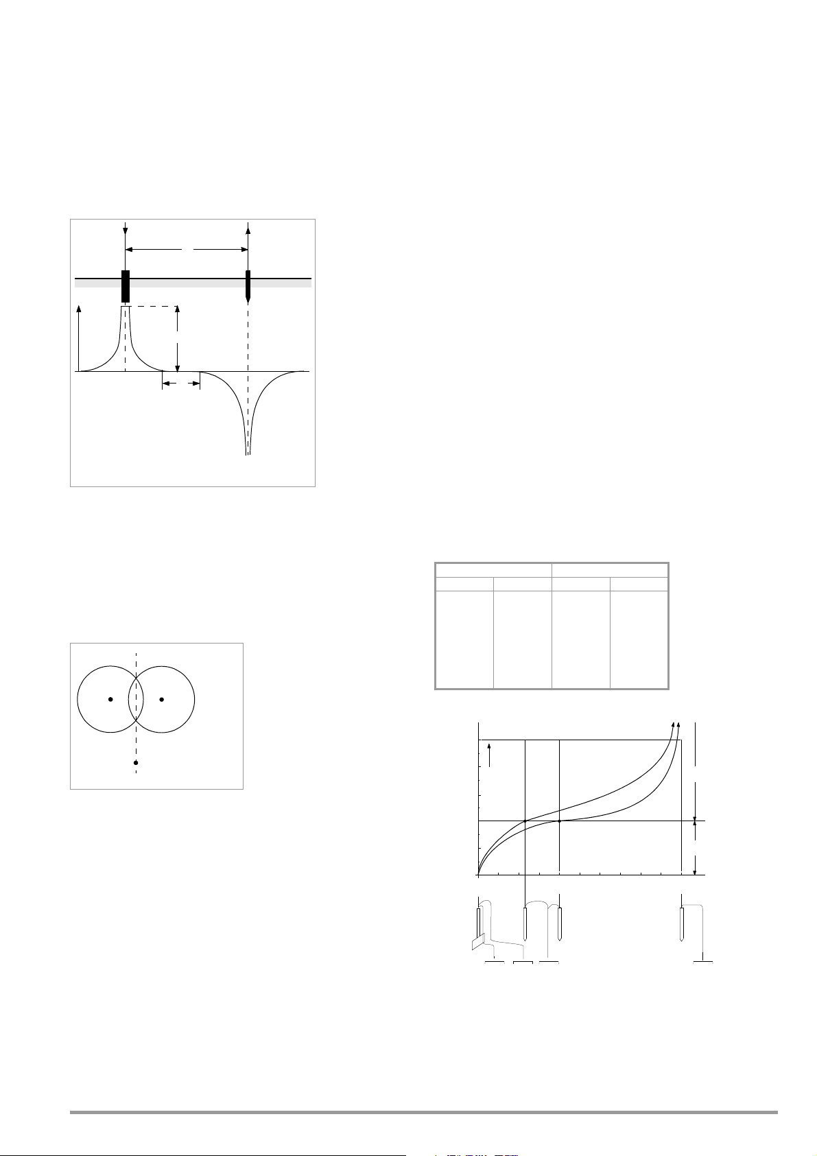
➭ Position the probe halfway between the earth electrode and
d = distance, electrode to aux. electrode
E = earth electrode
H = auxiliary earth electrode
I = measuring current
K = neutral zone (reference earth)
UE= earth potential
RE= UE / I = earthing resistance
Φ = potential
Φ
I
I
d
E
H
U
E
K
E = electrode location
H = aux. electrode loc.
S = probe location
S
HE
Curve I (KI) Curve II (KII)
mWmW
5
10
15
20
25
30
40
60
80
100
0.9
1.28
1.62
1.82
1.99
2.12
2.36
2.84
3.68
200
10
20
40
60
80
100
120
140
160
200
0.8
0.98
1.60
1.82
2.00
2.05
2.13
2.44
2.80
100
S1, S2 = inflection points
KI = curve I
KII = curve II
S1, S2 = inflection points
KI = curve I
KII = curve II
S
1
S
2
K I
K II
Ω
4
3
2
1
0
10 20 30 40 50 60 70 80 90 100 m KI
20 40 60 80 100 120 140 160 180 200 m KII
5
R
A/H
R
A/E
0
0
S HESE
the auxiliary earth electrode and determine earthing resistance.
➭ Reposition the probe 2 to 3 meters closer to the earth elec-
trode, and then 2 to 3 meters closer to the auxiliary earth electrode and measure earthing resistance in each position.
If all 3 measurements result in the same measured value, this is
the correct earthing resistance. The probe is in the neutral zone.
However, if the three measured values for earthing resistance differ from each other, either the probe is not located in the neutral
zone, or the voltage or resistance curve is not horizontal at the
point at which the probe has been inserted.
Figure 10.8.2: Voltage Curve in Homogenous Earth between Earth
Electrode E and Auxiliary Earth Electrode H
Correct measurements can be obtained in such cases by either
increasing distance between the earth electrode and the auxiliary
earth electrode, or by moving the probe to the perpendicular
bisector between the earth electrode and the auxiliary earth electrode (see also Figure 10.8.3:). When the probe is moved to the
perpendicular bisector, its location is removed from the sphere of
influence of the two potential gradient areas caused by the earth
electrode and the auxiliary earth electrode.
➭ Auxiliary earth electrode H is positioned as far from possible
from the earthing system.
➭ The area between the earth electrode and the auxiliary earth
electrode is sampled in equal steps of 5 meters each.
➭ Measured resistance values are displayed as a table, and then
plotted graphically as depicted in Figure 10.8.4: (curve I).
If a line parallel to the abscissa is drawn through inflection point
S1, this line divides the resistance curve into two parts.
Measured at the ordinate, the bottom part results in sought dissipation resistance of the earth electrode R
equals dissipation resistance of the auxiliary earth electrode R
With a measurement setup of this type, dissipation resistance of
, and the top value
A/E
A/H
the auxiliary earth electrode should be less than 100 times the
dissipation resistance of the earth electrode.
In the case of resistance curves without a well defined horizontal
area, measurement should be double checked after repositioning
the auxiliary earth electrode. This additional resistance curve must
be entered to the first diagram with a modified abscissa scale
such that the two auxiliary earth electrode locations are superimposed. The initially ascertained dissipation resistance value can
be checked with inflection point S2 (see Figure 10.8.4:).
Notes Regarding Measurement in Difficult Terrain
In extremely unfavorable terrain (e.g. sandy soil after a lengthy
period without rain), auxiliary earth electrode and probe resistance
can be reduced to permissible values by watering the ground
around the auxiliary earth electrode and the probe with soda
water or salt water. If this does not suffice, several earth spikes
can be parallel connected to the auxiliary earth electrode.
In mountainous terrain or in the case of very rocky subsoil where
earth spikes cannot be driven into the ground, wire grates with a
mesh size of 1 cm and a surface area of about 2 square meters
can be used. These grates are laid flat onto the ground, are wetted with soda water or salt water and may also be weighted down
with sacks full of moist earth.
.
Figure 10.8.3: Probe Distance S Outside of the Overlapping Potential
Gradient Areas on the Perpendicular Bisector of Earth
Electrode E and Auxiliary Earth Electrode H
Dissipation Resistance of Large Scope Earthing Systems
Significantly large distances to the probe and the auxiliary earth
electrode are required for measuring large scope earthing systems. Calculations are based on 2½ or 5 times the value of the
earthing system’s largest diagonal.
Large scope earthing systems of this sort often demonstrate dissipation resistances of only a few ohms, which makes it especially
important to position the measuring probe within the neutral zone.
The probe and the auxiliary earth electrode should be positioned
at a right angle to the direction of the earthing system’s largest linear expansion. Dissipation resistance must be kept small. If necessary, several earth spikes must be used at a distance of 1 to
2 m from each other and connected to this end.
However, in actual practice large measuring distances are frequently not possible to due difficult terrain. If this is the case, proceed as shown in Figure 10.8.4:.
GMC-I Messtechnik GmbH 39
Figure 10.8.4: Earthing Resistance Measurement for a Large Scope
Earthing System
Page 40

10.9 Earthing Resistance Measurement, Battery Operated – Selective (4-pole)
Note
PROFITEST MPRO, PROFITEST MXTRA
R
E
with Current Clamp Sensor and PRO-RE Measuring Adapter as Accessory (only MPRO & MXTRA)
General
Set Parameters at Tester
❑ Measuring range: 200 Ω
After switching to selective measurement, the AUTO
measuring range is activated automatically if a measuring
range of greater than 200 Ω had been selected.
❑ Connection type: selective
❑ Current clamp sensor transformer ratio:
1:1 (1 V/A,) 1:10 (100 mV/A), 1:100 (10 mV/A)
❑ Distance d (for measuring ρ
Set Parameters at Current Clamp Sensor
❑ Current clamp sensor measuring range: see table below
Selecting a Measuring Range at the Current Clamp Sensor
When measuring earthing resistance in systems with several parallel connected earth electrodes, total resistance of the earthing
system is measured.
Two earth spikes (auxiliary earth electrode and probe) are set for
this measurement. Measuring current is fed between the earth
electrode and the auxiliary earth electrode and voltage drop is
measured between the earth electrode and the probe.
The current clamp is positioned around the earth electrode to be
measured, and thus only that portion of the measuring current
which flows through the earth electrode is measured.
Tester Z3512A Clamp
Tra ns form a-
tion Ratio
Parameter
1:1
1 V / A
1:10
100 mV / A
1:100
10 mV / A
100 A / x 100 100 A
Important Instructions for Use of the Current Clamp Sensor
Connection
➭ Position the spikes for the probe and the auxiliary electrode at
least 20, respectively 40 meters from the electrode (see figure
above).
➭ Make sure that no excessively high contact resistances occur
between the probe and the ground.
➭ Attach the PRO-RE adapter (Z501S) to the test plug.
➭ Connect the probes, the auxiliary electrode and the electrode
via the 4 mm banana plug sockets at the PRO-RE adapter.
In doing so, observe labeling on the banana plug sockets.
➭ Connect the Z3512A current clamp sensor to jacks 15 and 16 at
the test instrument.
➭ Attach the current clamp sensor to the earth electrode.
• Use only the Z3512A current clamp sensor for this measurement.
•Use the clamp in the permanently connected state. The sensor
may not be moved during measurement.
• The current clamp sensor may only be used at an adequate
distance from powerful extraneous fields.
• Make sure that the current clamp sensor’s connector cable is
laid separate from the probe cables to the greatest possible
extent.
Start Measurement
): irrelevant in this case
E
Switch Measuring
1 A / x 1 1 A
10 A / x 10 10 A
Range
Select Measuring Function
Select Operating Mode
The selected operating mode is displayed inversely:
white battery icon against black background.
40 GMC-I Messtechnik GmbH
Page 41

10.10 Earthing Resistance Measurement, Battery Powered – Ground Loop Measurement
Note
PROFITEST MPRO, PROFITEST MXTRA
R
E
(with current clamp sensor and transformer, plus PRO-RE/2 measuring adapter as accessory) (only MPRO & MXTRA)
2-Clamp Measuring Method
Select Measuring Function
Select Operating Mode
The selected operating mode is displayed inversely:
white battery icon against black background.
Set Parameters at Tester
❑ Measuring range: in this case always AUTO
After selecting to 2-clamp measurement, switching to the
In the case of earthing systems which consist of several earth electrodes (R1 ...
Rx) which are connected to
each other, earthing resistance of a single electrode
(Rx) can be ascertained with
the help of 2 current clamps
without disconnecting Rx or
using spikes.
❑ Connection type: 2-clamp
❑ Current clamp sensor transformer ratio:
❑ Distance d (for measuring
Set Parameters at Current Clamp Sensor
❑ Current clamp sensor measuring range: see table below
AUTO range takes place automatically. It is then no longer
possible to change the range!
1:1 (1 V/A), 1:10 (100 mV/A), 1:100 (10 mV/A)
ρ
): irrelevant in this case
E
This measuring method is
especially well suited for
buildings or systems for
which probes and auxiliary
earth electrodes cannot be used, or where it’s impermissible to
disconnect earth electrodes.
Furthermore, this “spike-free” measurement is performed as one
of three measurements for lightning protection systems, in order
to determine whether or not current can be dissipated.
Figure at right:
PRO-RE/2 measuring adapter as
accessory for connecting the E-
Selecting a Measuring Range at the Current Clamp Sensor
Tester Z3512A Clamp
Tra ns form a-
tion Ratio
Parameter
1:1
1 V / A
1:10
100 mV / A
1:100
10 mV / A
Switch Measuring
Range
1 A / x 1 1 A
10 A / x 10 10 A
100 A / x 100 100 A
Clip 2 generator current clamp
Important Instructions for Use of the Current Clamp Sensor
• Use only the Z3512A current clamp sensor for this measurement.
•Use the clamp in the permanently connected state. The sensor
may not be moved during measurement.
• The current clamp sensor may only be used at an adequate
distance from powerful extraneous fields.
Connection
• Make sure that the connector cables from the two clamps are
laid separate from each other to the greatest possible extent.
Start Measurement
➭ No probes or auxiliary earth electrodes are required.
➭ The earth electrode is not disconnected.
➭
Attach the
PRO-RE/2 adapter (Z502T)
to the test plug.
➭ Connect the E-Clip 2 generator clamp (current clamp transformer)
via the 4 mm safety plugs at the PRO-RE/2 adapter.
➭ Connect the Z3512A current clamp sensor to jacks 15 and 16 at
the test instrument.
➭ Attach the 2 clamps to an earth electrode (earth spike) at dif-
ferent heights with a clearance of at least 30 cm.
GMC-I Messtechnik GmbH 41
Page 42

10.11 Earthing Resistance Measurement, Battery Powered
Note
ES ESH
dd d
R
E
– Measurement of Soil Resistivity ρ
(only MPRO & MXTRA)
E
General
Select Measuring Function
Select Operating Mode
The selected operating mode is displayed inversely:
white battery icon against black background.
Measurement of Soil Resistivity
The determination of soil resistivity is necessary for the planning of
earthing systems. Reliable values need to be ascertained which
take even the worst possible conditions into account (see “Geologic Evaluation” on page 43).
Soil resistivity is decisive with regard to the magnitude of an earth
electrode’s dissipation resistance. Soil resistivity can be measured
with the PROFITEST MASTER using the method according to Wenner.
Four earth spikes of greatest possible length are driven into the
ground in a straight line at distance d from one another, and are
connected to the earth tester (see figure above).
The earth spikes usually have a length of 30 to 50 cm. Longer
earth spikes can be used for soil which demonstrates poor conductivity (sandy soil etc.). The depth to which the earth spikes are
driven into the ground may not exceed one twentieth of distance
d.
Erroneous measurement may result in the event that piping, cables or other underground metal conduits run parallel to the measuring setup.
Soil resistivity is calculated as follows:
ρE=2π ⋅ d ⋅ R
Where:
π = 3.1416
d = distance in m between two earth spikes
R = ascertained resistance value in Ω (this value corresponds to R
determined with the 4-wire method)
E
as
Set Parameters
❑ Measuring range: AUTO, 50 kΩ, 20 kΩ, 2 kΩ, 200 Ω, 20 Ω
❑ Connection type:
ρ
(Rho)
E
❑ Transformer ratio: irrelevant in this case
❑ Distance d for measurement of
ρ
: adjustable from 0.1 to 999 m
E
Start Measurement
Connection
➭ Position the spikes for the probe and the auxiliary electrode at
equal distances (see figure above).
➭ Make sure that no excessively high contact resistances occur
between the probe and the ground.
➭ Attach the PRO-RE adapter (Z501S) to the test plug.
➭ Connect the probes, the auxiliary electrode and the electrode
via the 4 mm banana plug sockets at the PRO-RE adapter.
In doing so, observe labeling on the banana plug sockets.
42 GMC-I Messtechnik GmbH
Page 43

Geologic Evaluation
+ρE (%)
10
20
30
-10
-20
-30
Jan. MarchMay July Sept. Nov.
R
A
2 ρ
E
⋅
I
----------=
R
A
ρ
E
I
----=
R
A
2 ρ
E
⋅
3D
----------=
D 1,13 F
2
⋅=
R
A
2 ρ
E
⋅
2D
----------=
D 1,13 F
2
⋅=
R
A
2 ρ
E
⋅
4,5 a⋅
----------=
R
A
ρ
E
π D
⋅
--------=
D 1,57 J
3
⋅=
Except in extreme cases, the ground is measured down to a
depth which is roughly equal to probe distance d.
This makes it possible to arrive at conclusions regarding the
ground’s stratification by varying probe distance. Layers which
are highly conductive (water table), into which earth electrodes
should be installed, can thus be discovered within a region which
is otherwise poorly conducting.
Soil resistivity is subject to considerable fluctuation which may be
due to various causes such as porosity, moisture penetration,
concentration of dissolved salts in the ground water and climatic
fluctuation.
Characteristic values for ρ
and the soil’s negative temperature coefficient) can be approximated quite closely by means of a sinusoidal curve.
relative to season (soil temperature
E
Calculating Dissipation Resistance
Formulas for calculating dissipation resistance for common types
of earth electrodes are included in this table.
These rules of thumb are entirely adequate for actual practice.
Number Earth Electrode Rule of Thumb Subsidiary Variable
Earth strip (star type earth
1
2
3 Ring earth electrode
4 Mesh earth electrode
5 Ground plate —
6
electrode)
Earth rod (buried earth
electrode)
Hemispherical earth elec-
trode
—
—
Soil Resistivity ρE Relative to Season Without the Effects of Precipitation
(earth electrode depth < 1.5 m)
A number of typical soil resistivity values for various types of
ground are summarized in the following table.
Type of Soil Soil Resistivity ρ
Marshy ground 8 … 60
Arable soil, loamy and clayey
soil, moist gravel
20 … 300
Moist sandy soil 200 … 600
Dry sandy soil, dry gravel 200 … 2000
Rocky ground 300 … 8000
Rock 10
Soil Resistivity ρ
with Different Types of Soil
E
4
… 10
[Ωm]
E
10
Formulas for Calculating Dissipation Resistance R
for Various Earth
A
Electrodes
RA= dissipation resistance (Ω)
ρ
= soil resistivity (Ωm)
E
I = length of the earth electrode (m)
D = diameter of a ring earth electrode, diameter of the equivalent surface
area of a mesh earth electrode or diameter of a hemispherical earth
electrode (m)
F = surface area (sq. meters) of the enclosed surface or a ring or mesh
earth electrode
a = Edge length (m) of a square ground plate; a is replaced with the fol-
lowing for rectangular plates: √
sides of the rectangle.
J = volume (cubic meters) of an individual foundation footing
bxc, where b and c are the two
GMC-I Messtechnik GmbH 43
Page 44

11 Measuring Insulation Resistance
Attention!
!
Note
Note
R
ISO RINS
Voltage type: constant
Test volta g e : 50 V / 100 V / 250 V / 325 V / 500 V / 1000 V
Voltage type: rising/ramp
Earth leakage resistance:
xxx V*
2-pole meas. (relevant for report generating only):
Measurements between
Lx-PE / N-PE / L+N-PE / Lx-N / Lx-Ly / AUTO*
where x, y = 1, 2, 3
Limit value:
I > I
Limit
U
INS
STOP
low limit:
U
INS
input range:
> 40 V ... < 999 V
upper limit:
Limit value:
R
INS
< Limit Value
UL ⏐ R
L
U
INS
Insulation resistance can only be measured at voltagefree objects.
11.1 General
Select Measuring Function
Connection
2 pole adapter or test
plug
Breakdown current for Ramp Function
Limit values for Breakdown Voltage
Limit Values for Constant Test Voltage
The test instrument measures the insulation between the
contacts L and PE.
In systems without RCD, N and PE must be seperated.
Checking Measurement Cables Before Measurements
Before performing insulation measurement, the test
probes on the measurement cables should be short-circuited in order to assure that the instrument displays a
value of less than 1 kΩ. In this way, incorrect connection
can be avoided and broken measurement cables can be
detected.
Set Parameters
❑ Test voltage
A test voltage which deviates from nominal voltage, and is usually
lower, can be selected for measurements at sensitive components, as well as systems with voltage limiting devices.
❑ Voltage Type
The “U
detect weak points in the insulation, as well as to determine
” rising test voltage function (ramp function) is used to
INS
response voltage for voltage limiting components. After briefly
pressing the ON/START key, test voltage is continuously increased
until specified nominal voltage U
which is measured at the test probes during and after testing. This
is reached. U is the voltage
N
voltage drops to a value of less than 10 V after measurement (see
section entitled “Discharging the Device Under Test”).
Insulation measurement with rising test voltage is ended:
• As soon as specified maximum test voltage U
the measured value is stable
is reached and
N
or
• As soon as specified maximum test voltage is reached, e.g.
after sparkover occurs at breakdown voltage).
Specified maximum test voltage U
breakdown voltage is displayed for U
or any occurring triggering or
N
.
INS
* Freely adjustable voltage (see section 5.7)
Polarity Selection
* AUTO parameter (see section 5.8)
44 GMC-I Messtechnik GmbH
The constant test voltage function offers two options:
• After briefly pressing the ON/START key, specified test voltage
UN is read out and insulation resistance RINS is measured. As
soon as the measured value is stable (settling time may be
several seconds in the case of high cable capacitance values),
measurement is ended and the last measured values for RINS
and UINS are displayed. U is the voltage which is measured at
the test probes during and after testing. This voltage drops to a
value of less than 10 V after measurement (see section entitled “Discharging the Device Under Test”).
Page 45

or
Note
Note
Attention!
!
• As long as you press and hold the ON/START key, test voltage
UN is applied and insulation resistance R
not release the key until the measured value has settled in
(settling time may be several seconds in the case of high cable
capacitance values). Voltage U, which is measured during
testing, corresponds to voltage UINS. After releasing the ON/
START key, measurement is ended and the last measured
values for R
less than 10 V after measurement (see section entitled “Discharging the Device Under Test”).
❑ Pole Selection Report Entry
The poles between which testing takes place can only be entered
here for reporting purposes. The entry itself has no influence on
the actual polarity of the test probes or pole selection.
❑ Limits – Setting the Limit Value
The limit value for insulation resistance can be set as desired. If
measurement values occur which are below this limit value, the
red U
0.5 to 10 MΩ is available. The limit value is displayed above the
measured value.
LED lights up. A selection of limit values ranging from
L/RL
and UINS are displayed. U drops to a value of
INS
is measured. Do
INS
Start Measurement – Rising Test Voltage (ramp function)
Press briefly:
Testing of overvoltage limiters or varistors
and determining their tripping voltage:
– Select maximum voltage such that the anticipated breakdown
voltage of the device under test is roughly one third of this
value (observe manufacturer’s data sheet if applicable).
– Select current limit value in accordance with actual require-
ments or the manufacturer’s data sheet (characteristic curve
of the device under test).
Determining tripping voltage for spark gaps:
– Select maximum voltage such that the anticipated breakdown
voltage of the device under test is roughly one third of this
value (observe manufacturer’s data sheet if applicable).
– Select the current limit value in accordance with actual
requirements within a range of 5 to 10 A (response characteristics are too unstable with larger current limit values, which
may result in faulty measurement results).
Detecting weak points in the insulation:
– Select maximum voltage such that it does not exceed the test
object’s permissible insulation voltage; it can be assumed that
an insulation fault will occur even with a significantly lower
voltage if an accordingly lower maximum voltage value is
selected (nevertheless at least greater than anticipated breakdown voltage) – the ramp is less steep as a result (increased
measuring accuracy).
– Select the limit current value in accordance with actual
requirements within a range of 5 to 10 A (see also settings
for spark gaps).
Quick polarity reversal if parameter is set to AUTO: 01/10 ... 10/10: L1-PE
... L1-L3
If “semiautomatic polarity reversal” is selected (see section 5.8), the corresponding icon is displayed instead of
the ramp.
General Notes Regarding Insulation Measurements with Ramp
Function
Insulation measurement with ramp function serves the following
purposes:
• Detect weak points in the test object’s insulation
• Determine tripping voltage of voltage limiting components and
test them for correct functioning These components may
include, for example, varistors, overvoltage limiters (e.g.
DEHNguard® from Dehn+Söhne) and spark gaps.
The test instrument uses continuously rising test voltage for this
measuring function, up to the maximum selected voltage limit.
The measuring procedure is started by pressing the START/
STOPP key and runs automatically until one of the following
events occurs:
• The selected voltage limit is reached
• The selected current limit is reached
• Sparkover occurs (spark gaps)
Differentiation is made amongst the following three procedures for
insulation measurement with ramp function:
Start Measurement – Constant Test Voltage
Long-term measurements
Press and hold:
Quick polarity reversal if parameter is set to AUTO: 01/10 ... 10/10:
L1-PE ... L1-L3
The instrument’s batteries are rapidly depleted during the
insulation resistance measurement. When using the
“constant test voltage” function, only press and hold the
Start
▼ key until the display has become stable (if long-
term measurement is required).
Special Condition for Insulation Resistance Measurement
Insulation resistance can only be measured at voltagefree objects.
If measured insulation resistance is less than the selected limit
value, the U
If an interference voltage of
insulation resistance is not measured. The MAINS/NETZ LED
lights up and the “interference voltage” pop-up message appears.
All conductors (L1, L2, L3 and N) must be tested against PE!
LED lights up.
L/RL
≥ 25 V is present within the system,
GMC-I Messtechnik GmbH 45
Page 46

Attention!
!
Do not touch the instrument’s terminal contacts during
Attention!
!
R
ISO RINS
Limit value:
RE(ISO) > limit value
UL ⏐ R
L
R
EISO
Voltage type: constant
Test v o l t a ge : 50 V / 100 V / 250 V / 325 V / 500 V / 1000 V*
Voltage type: rising/ramp
Earth leakage
resistance:
insulation resistance measurements!
If nothing has been connected to the terminal contacts, or if a
resistive load component has been connected for measurement,
your body would be exposed to a current of approx. 1 mA at a
voltage of 1000 V.
The noticeable shock may lead to injury (e.g. resulting from a startled reaction etc.).
Discharging the Device Under Test
If measurement is performed at a capacitive object such
as a long cable, it becomes charged with up to approx.
1000 V!
Touching such objects is life endangering!
When an insulation resistance measurement has been performed
on a capacitive object it is automatically discharged by the instrument after measurement has been completed. Contact to the
device under test must be maintained to this end. The falling voltage value can be observed at the U display.
Do not disconnect the DUT until less than 10 V is displayed for U!
Evaluation of Measured Values
Instrument measuring error must be taken into consideration in
order to assure that the limit values set forth in DIN VDE regulations are not fallen short of. The required minimum display values
for insulation resistance can be determined with the help of Table
3 on page 88. These values take maximum device error into consideration (under nominal conditions of use). Intermediate values
can be interpolated.
* Freely adjustable voltage (see section 5.7)
Connection and Test SetUp
11.2 Special Case: Earth Leakage Resistance (R
This measurement is performed in order to determine electrostatic discharge capacity for floor coverings in accordance with
EN 1081.
EISO
)
Select Measuring Function
Set Parameters
➭ Rub the floor covering at the point at which measurement is to
be performed with a dry cloth.
➭ Place the 1081 floor probe onto the point of measurement
and load it with a weight of at least 300 N (30 kg).
➭ Establish a conductive connection between the measuring
electrode and the Test Probe and connect the measuring
adapter (2-pole) to an earth contact, e.g. the earthing contact
at a mains outlet or a central heating radiator (prerequisite: reliable ground connection).
Start Measurement
The limit value for earth leakage resistance from the relevant regulations applies.
46 GMC-I Messtechnik GmbH
Page 47

12 Measuring Low-Value Resistance
Attention!
!
Note
Note
R
LO
ROFFSET: ON ↔ OFF
Polarity: +/- to PE
Polarity: +/- to PE
with ramp function
Limit value:
RLO > Limit Value
UL ⏐ R
L
up to 200 Ohm
(protective conductor and equipotential bonding
conductor)
According to the regulations, the measurement of low-value resistance at protective conductors, earth conductors or bonding conductors must be performed with (automatic) polarity reversal of
the test voltage, or with current flow in one (+ pole to PE) and then
the other direction (– pole to PE).
Low-value resistance must only be measured at voltagefree objects.
Select Measuring Function
Connection
Via 2-pole adapter only!
❑ ROFFSET ON/OFF
– Compensation for Extension Cables with up to 10 Ω
If measurement cables or extension cables are used, their resistance can be deducted automatically from the measurement
results. Proceed as follows:
➭ Switch R
the footer.
➭ Select a polarity option or automatic polarity reversal.
➭ Short-circuit the end of the measurement extension cable with
the second test probe at the instrument.
➭ Start measurement of offset resistance with I
An intermittent acoustic signal sounds first,
which is then accompanied by a blinking
warning to prevent an offset value which has
already been saved from being unintentionally
deleted.
➭
Start the offset measurement by pressing the release key again or abort measurement by pressing the
(here = ESC).
OFFSET from OFF to ON. “ROFFSET = 0.00 Ω” appears in
.
ΔN
key
?
ON/START
If the offset measurement is stopped by an error pop-up
(Roffset > 10 Ω or difference between RLO+ and RLO–
greater than 10%), the offset value that has last been
measured is retained. Inadvertent deletion of an offset
value once established is thus almost ruled out! The
respectively smaller value is otherwise stored to memory
as an offset value. The maximum offset value is 10.0 Ω.
Negative resistances may result due to the offset value.
Set Parameters
Measuring ROFFSET
The ROFFSET x.xx Ω message now appears in the footer at the display, where x.xx may take a value between 0.00 and 10.0 Ω. This
value is subtracted from the actual measuring results for all subsequent R
set to ON.
Roffset must be determined anew in the following cases:
• After switching to a different polarity option
• After switching from ON to OFF and back again
You can deliberately delete the offset value by switching ROFF-
SET from OFF to ON.
measurements, if the ROFFSET ON/OFF key has been
LO
Only use this function when performing measurements
with extension cables.
When different extension cables are used, the above
described procedure must always be repeated.
GMC-I Messtechnik GmbH 47
❑ Type / Polarit y
The direction in which current flows can be selected here.
❑ Limits – Setting the Limit Value
The limit value for resistance can be set as desired. If measurement values which exceed this limit occur, the red U
lights up. Limit values can be selected between 0.10 Ω and
10.0 Ω (editable). The limit value is displayed above the measured
value.
L/RL
LED
Page 48

12.1 Measurements with Constant Test Current
Attention!
!
Note
Start Measurement
Press and hold for
long-term measurement
The test probes should always be in contact with the DUT before pressing the Start
If the object is energized, measurement is disabled as soon as
it is contacted with the test probes.
If the Start
tacted with the test probes afterwards, the fuse blows.
Which of the two fuses has blown is indicated in the pop-up
window with the error message by means of an arrow.
In the case of single-pole measurement, the respective value is
saved to the database as RLO.
▼ key is pressed first and the test object is con-
▼ key.
Measuring Low-Value Resistance
Measurement cable and 2-pole measuring adapter resistance is compensated for automatically thanks to the four
conductor method and thus do not effect measurement
results. However, if an extension cable is used its resistance must be measured and deducted from the measurement results.
Resistances which do not demonstrate a stable value
until after a “settling in period” should not be measured
with automatic polarity reversal, but rather one after the
other with positive and negative polarity.
Examples of resistances whose values may change
during measurement include:
– Incandescent lamp resistance, whose values change
due to warming caused by test current
– Resistances with a great conductive component
– Contact resistance
Evaluation of Measured Values
See Table 4 on page 88.
Calculation of Cable Lengths for Common Copper Conductors
If the HELP key is activated after performing resistance measurement, the cable lengths corresponding to common conductor
cross sections are displayed.
Polarity Selection Display Condition
+ pole to PE RLO+ None
– pole to PE RLO– None
RLO If ΔRLO ≤ 10%
± pole to PE
RLO+
RLO–
If ΔRLO > 10%
Automatic Polarity Reversal
After the measuring sequence has been started, the instrument
performs measurement with automatic polarity reversal, first with
current flow in one direction, and then in the other. In the case of
long-term measurement (press and hold START key), polarity is
switched once per second.
If the difference between RLO+ and RLO– is greater than 10%
with automatic polarity reversal, RLO+ and RLO– values are displayed instead of RLO. The respectively larger value, RLO+ or
RLO–, appears at the top and is saved to the database as the
RLO value.
Evaluating Measurement Results
Differing results for measurements in both directions indicate voltage at the DUT (e.g. thermovoltages or unit voltages).
Measurement results can be distorted by parallel connected
impedances at load current circuits and by equalizing current,
especially in systems which make use of “overcurrent protection
devices” (previous neutralization) without an isolated protective
conductor. Resistances which change during measurement (e.g.
inductance), or a defective contact, can also cause distorted
measurements (double display).
In order to assure unambiguous measurement results, causes of
error must be located and eliminated.
In order to find the cause of the measuring error, measure resistance in both current flow directions.
If results vary for the two different current flow directions, cable
length is not displayed. In this case, capacitive or inductive components are apparently present which would distort the calculation.
This table only applies to cables made with commercially available
copper conductors and cannot be used for other materials (e.g.
aluminum)!
The instrument’s batteries are exposed to excessive stress during
insulation resistance measurement. For measurement with current flow in one direction, only press and hold the START
long as is necessary for the measurement.
48 GMC-I Messtechnik GmbH
▼ key as
Page 49

12.2 Protective Conductor Resistance Measurement with Ramp Curve
Note
Measuring phase Demagnetization
and waiting period
Result
Time [s]
Rise
phase
Test C u rre n t [A]
01 3 6
0.25
prior to polarity reversalorrestart
– Measurements on PRCDs with Current-monitored Protective Conductor Using PROFITEST PRCD Test Adapter as Accessory
Application
In certain PRCD types, the protective conductor current is monitored. Direct application or disconnection of the test current of
200 mA, which is required for protective conductor resistance
measurements, results in tripping of the PRCD and, consequently, a cut-off of the protective conductor connection. Protective conductor measurement is no longer possible in this case.
A special ramp curve for the application or disconnection of the
test current in combination with the PROFITEST PRCD test adapter
allows for performing protective conductor resistance measurements without PRCDs being tripped.
Timed Sequence of the Ramp Function
Due to the physical properties of the PRCD, the measuring cycles
of this ramp function lie within the range of several seconds.
Moreover, while the polarity of the test current is being reversed,
an additional waiting period during polarity reversal becomes nec-
essary.
This waiting period has been included in the test sequence in
operating mode „automatic polarity reversal“ .
If you change the polarity direction manually, e.g. from „+pole with ramp“
to „–pole with ramp“
, the test instrument recognizes the change in the current flow direction, disables measurements for the
required waiting period and simultaneously shows the respective symbol, see figure on the right.
Connection
➭ Please consult the operating instructions of the PROFITEST
PRCD adapter, particularly chapter 4.1. There you will also find
information on the connection terminals for offset measurements and protective conductor resistance measurements.
Selecting Polarity Parameter
➭ Select the requested polarity parameter with
ramp.
Measuring ROFFSET
➭ Perform an offset measurement as described on page 47, to
assure that the test adapter‘s connector contacts are not included in the measurement results.
The offset only remains saved to memory until you
change the polarity parameter. If you perform the measurement with manual polarity reversal (+pole or –pole),
you have to repeat the offset measurement before each
measurement with another polarity.
Measuring Protective Conductor Resistance
➭ Check whether the PRCD is activated. If this is not the case,
activate it.
➭ Perform the protective conductor measurement as described
above in section 12.1. Start the test sequence by briefly
pressing key ON/START. By pressing and holding key ON/START
you can extend the preset duration of the measuring phase.
Start measurement
Visualization of the measuring and waiting phases during protective conductor resistance measurements on PRCDs with the PROFITEST MXTRA
Tripping of a PRCD due to faulty contact
During measurement, safe contact between the test probes of the
2-pole adapter and the DUT or the sockets of the PROFITEST PRCD
test adapter is to be ensured. Interruptions may lead to heavy
fluctuations in the test current which may cause the PRCD to trip
in the worst case.
In this event, the tripping of the PRCD is
automatically recognized by the test
instrument as well and an error message
is generated, see figure on the right. In
this case as well, the test instrument
automatically takes into account the
required waiting period before reenabling the PRCD and allowing any new measurements.
GMC-I Messtechnik GmbH 49
During the magnetization phase (rising curve) and the
subsequent measuring phase (constant current) the
symbol on the right is shown.
If you abort the measurement during the rise phase, no measuring result can be issued and displayed.
After the measurement, the demagnetization phase
(declining curve) and a subsequent waiting period is signalled with the inverse symbol shown on the right.
During this period, no new measurements are possible.
Only when the symbol on the right is shown, can the
measurement result be read and measurements started
with the same or another polarity.
Page 50

13 Measurement with Accessory Sensors
Attention!
!
Attention!
!
Attention!
!
SENSOR
Output range,
clamp
Limit value:
I < and I > limit value
UL ⏐ R
L
“IΔ” with METRAFLEX⏐P300
13.1 Current Measurement with Current Clamp Sensor
Bias, leakage and circulating current to 1 A, as well as leakage
current to 1000 A can be measured with the help of special current clamp sensors, which are connected to sockets 15 and 16.
Danger: High-Voltage!
Use only current clamp sensors which are specifically offered as accessories by GMC-I Messtechnik GmbH.
Other current clamp sensors might not be terminated
with an output load at the secondary side. Dangerously
high voltage may endanger the user and the device in
such cases.
Maximum input voltage at the test instrument!
Do not measure any currents which are greater than
specified for the measuring range of the respective
clamp.
Input voltage for clamp connector sockets 15 and 16 at
the test instrument may not exceed 1 V!
Set Parameters
The transformation ratio parameter must be correspondingly set
at the test instrument depending upon the respectively selected
measuring range at the current clamp sensor.
Be sure to read and adhere to the operating instructions for
current clamp sensors and the safety precautions included therein, especially those regarding the approved
measuring category.
Select Measuring Function
Selecting a Measuring Range at the Current Clamp Sensor
Tester Clamp Tester
Transforma-
tion Ratio
Parameter
1:1
1 V / A
1:10
100 mV / A
1:100
10 mV / A
1:1000
1 mV / A
Tester Clamp Tester
Transforma-
tion Ratio
Parameter
1:1
1 V / A
1:10
100 mV / A
1:100
10 mV / A
Switch
WZ12C
1 mV / mA
— x 100 [mV/A] — 0 ... 10 A 0.05 ... 10 A
— x 10 [mV/A] — 0 ... 100 A 0.5 ... 100 A
1 mV / A x 1 [mV/A] 1 A ... 150 A 0 ... 1000 A
Switch
METRAFLEX P300
3 A (1 V/A) 3 A 5 ... 999 mA
30 A (100 mV/A) 30 A 0.05 ... 10 A
300 A (10 mV/A) 300 A 0.5 ... 100 A
Switch
Z3512A
x 1000 [mV/
A]
Measuring Range
METRAFLEX P300
Measuring
Range
WZ12C
1 mA ... 15 A 0 ... 1 A 5 ... 999 mA
Measuring
Range
Z3512A
Measuring
Range
Specifying limit values results in automatic evaluation at the end of
the measurement.
Connection
Measuring
Range
5 ... 150 A/
999 A
Start Measurement
50 GMC-I Messtechnik GmbH
Page 51

14 Special Functions – EXTRA Switch Position
EXTRA
Select EXTRA Switch Position
Overview of Special Functions
Selecting Special Functions
The list of special functions is accessed by pressing the uppermost softkey. Select the desired function with the requested icon.
Softkey Meaning / Spe-
cial Function
Voltage drop
measurement
ΔU function
Standing surface insulation
impedance
Z
function
ST
Meter start-up
test
kWh function
Leakage Current Measurement
I
function
L
Check insulation monitoring
device
IMD function
Residual volt-
age test
Ures function
Intelligent ramp
ta + IΔ function
Residual current monitor
(RCM)
RCM function
Testing the op-
erating states
of electric vehicles at charging
stations per
IEC 61851
Report generation of fault
simulations on
PRCDs with
PROFITEST
PRCD adapter
TECH+MPRO
M
MBASE+
✓✓
✓✓
✓✓
———✓
———✓
———✓ —
———✓ —
———✓ —
—
✓
———
MXTRA
✓✓
✓✓
✓✓
✓
✓
—
✓
✓
— ✓ —
—
✓
Section /
Page
SECULIFE IP
section
14.1
page
52
section
14.2
page
53
section
14.3
page
54
section
14.4
page
55
section
14.5
page
56
section
14.6
page
58
section
14.7
page
59
section
14.8
page
60
section
14.9
page
61
section
14.10
page
62
GMC-I Messtechnik GmbH 51
Page 52

14.1 Voltage Drop Measurement (at ZLN) – ΔU Function
1
2
Nominal current of the fuse:
Polarity selection: Lx-N
Diameter: 1.5 to 70 sq. mm
Cable types: NY..., H03... - H07...
Number of wires: 2 ... 10-strand
Tripping characteristics: B, L
2 to 160 A
Limit value
ΔU % > limit value
UL ⏐ R
L
ΔU
Red
2
Significance and Display of ΔU (per DIN VDE 100, part 600)
Voltage drop from the intersection of the distribution network and
the consumer system to the point of connection of an electrical
power consumer (electrical outlet or device connector terminals)
should not exceed 4% of nominal line voltage.
Calculating voltage drop (without offset):
ΔU = Z
Calculating voltage drop (with offset):
ΔU = (Z
• nominal current of the fuse
L-N
L-N
- Z
) • nominal current of the fuse
OFFSET
Measurement without OFFSET
Proceed as follows:
➭ Switch OFFSET from ON to OFF.
ΔU in % = 100 • ΔU / U
See also section 9 regarding measurement procedure and connection.
L-N
Connection and Test Set-Up
Set Parameters
Determine OFFSET (as %)
Proceed as follows:
➭ Switch OFFSET from OFF to ON. “ΔUOFFSET = 0.00%” is dis-
played.
➭ Connect the test probe to the point of common coupling
(measuring device / meter).
➭ Start measurement of offset with IΔ
An intermittent acoustic signal sounds first,
which is then accompanied by a blinking
warning to prevent an offset value which has
already been saved from being unintentionally
deleted.
➭ Start the offset measurement by
pressing the release key again or
abort measurement by pressing the
key
▼ ON/START (here = ESC).
.
N
Note: When the nominal current IN is changed with existing
ΔU
the offset value is automatically adjusted.
OFFSET,
Setting Limit Values
ΔUOFFSET x.xx % is indicated, where x.xx may take a value
between 0.00 and 99.9 %.
An error message appears in a pop-up window in the event that
Z > 10 Ω.
Start Measurement with OFFSET
TAB Limit value per German technical connection conditions
for connection to low-voltage mains between the distribution network and the measuring device
DIN Limit value per DIN 18015-1: ΔU < 3% between the mea-
VDE Limit value per DIN VDE 0100-520: ΔU < 4% between the
NL Limit value per NIV: ΔU < 5%
52 GMC-I Messtechnik GmbH
suring device and the consuming device
distribution network and the consuming device (adjustable
up to 10% in this case)
Page 53

14.2 Measuring the Impedance of Insulating Floors and Walls
Attention!
!
OK
NOT OK
(standing surface insulation impedance) – Z
Function
ST
Measuring Method
The instrument measures the impedance between a weighted
metal plate and earth. Line voltage available at the measuring site
is used as an alternating voltage source. The ZST equivalent circuit
is considered a parallel circuit.
Connection and Test Set-Up
Start Measurement
Evaluate Measured Value
The measured value has to be evaluated after measurement has
been completed:
Note: Use the measuring set-up described in section 11.2 (trian-
gular probe) or the one outlined below:
➭ Cover the floor or the wall at unfavorable locations, e.g. at
joints or abutments, with a damp cloth measuring approx.
270 x 270 mm.
➭ Place the 1081 Probe on top of the damp cloth and load the
probe with a weight of 750 N (75 kg, i.e. one person) for
floors, or 250 N (25 kg) for walls, e.g. press against the wall
with one hand which is insulated with a glove.
➭ Establish a conductive connection to the 1081 Probe, and
connect it to the probe connector socket at the instrument.
➭ Connect the instrument to a mains outlet with the test plug.
Do not touch the metal plate or the damp cloth with your
bare hands.
No more than 50% line voltage may be applied to these
parts! Current with a value of up to 3.5 mA may flow!
The measured value would be distorted as well.
Resistance values must be measured at several points in order to
provide for adequate evaluation. Measured resistance may not be
less than 50 kΩ at any given point. If the measured value is
greater than 30 MΩ, Z
play panel.
In the event that “NOT OK” is selected, an error is indicated by the
UL/RL LED which lights up red.
See also Table 5 on page 89 with regard to evaluating measured
values.
The measured value cannot be saved to memory and included in
the test report until it has been evaluated.
> 30.0MΩ always appears at the dis-
ST
Save Measured Value
GMC-I Messtechnik GmbH 53
Page 54

14.3 Testing Meter Start-Up with Earthing Contact Plug
Note
Note
OK
NOT OK
– kWh Function (not SECULIFE IP)
Energy consumption meters can be tested for correct start-up
with this function.
Connection L – N
Earthing contact plug
Start Measurement
Save Measured Value
Special Case
Start-up of energy consumption meters which are connected
between L and L or L and N can be tested with this function.
Connection L – L
2-Pole Adapter
The meter is tested with the help of an internal load resistor and a
test current of approximately 250 mA. After pressing the start key,
test power is displayed and the meter can be tested for proper
start-up within a period of 5 seconds. The “RUN” pictograph is
displayed.
TN systems: All 3 phase conductors must be tested against N,
one after the other.
In other types of systems, all phase conductors (active conductors) must be tested against one another.
If minimum power is not reached, the test is either not
started or aborted.
Evaluate Measured Value
The measured value has to be evaluated after measurement has
been completed:
If an earthing contact outlet is not available, you can use
the 2-pole adapter. N must be contacted with the PE test
probe (L2), and then measurement must be started.
If PE is contacted with the PE test probe (L2) during the
meter start-up test, approximately 250 mA flow through
the protective conductor and any upstream RCD is
tripped.
In the event that “NOT OK” is selected, an error is indicated by the
UL/RL LED which lights up red.
The measured value cannot be saved to memory and included in
the test report until it has been evaluated.
54 GMC-I Messtechnik GmbH
Page 55

14.4 Leakage Current Measurement
Attention!
!
Note
with PRO-AB Leakage Current Adapter as Accessory
– I
Function (PROFITEST MXTRA & SECULIFE IP only)
L
Applications
Measurement of contact voltage in accordance with DIN VDE
0107, part 10, as well as continuous leakage and patient auxiliary
current per IEC 62353 (VDE 0750, part 1) / IEC 601-1 / EN 60
601-1:2006 (Medical electrical equipment – General requirements
for basic safety), is possible using the PRO-AB PRO-AB leakage
current measuring adapter as an accessory with the
PROFITEST MXTRA test instrument.
As specified in the standards listed above, current values of up to
10 mA may be measured with this measuring adapter. In order to
be able to fully cover this measuring range using the measurement input provided on the test instrument (2-pole current clamp
input), the measuring instrument is equipped with range switching
between transformation ratios of 10:1 and 1:1. In the 10:1 range,
voltage dividing takes place at the same ratio.
Connection and Test Set-Up
In order to perform the leakage current measurement, the
adapter’s measurement outputs must be plugged into the measurement inputs at the left-hand side of the PROFITEST MXTRA (2pole current clamp input and probe input).
Either of the leakage current measuring adapter’s inputs is connected to reference earth (e.g. safe earth electrode / equipotential
bonding) via a measurement cable. The metallic housing (accessible part) of the device under test is contacted with a test probe or
alligator clip which is connected to the other input by means of a
second measurement cable.
Measuring Sequence
Refer to the operating instructions for the PRO-AB leakage current measuring adapter regarding performance of the measurement.
The test plug should be located in the storage slot during
leakage current measurement. Under no circumstances
may the test plug be connected with any system components, including PE / ground potential (measured values
might otherwise be distorted).
The measurement can be started or stopped by pressing the
“START” key. Leakage current measurement is a long-term measurement, i.e. it continues until it is stopped by the user. The
momentary measured value is display continuously during measurement.
Testing the PRO-AB Adapter
The adapter should be tested before use and at regular intervals
(see adapter operating instructions).
The self-test must be deactivated in the menu (set
“TEST ON/OFF” function key to “OFF”) in order to perform a
measurement.
Always start with the large measuring range (10:1), unless there’s
no doubt that small measured values can be expected, in which
case the small measuring range can be used (1:1). The measuring
range must be selected at the measuring adapter, as well as in
the menu using the corresponding function key (RANGE). It must
be assured that the range settings at the adapter and at the test
instrument are always identical, in order to prevent any distortion
of measurement results.
Depending on the magnitude of the measured values, the range
setting can, or must (in the case of overranging), be manually corrected at the measuring adapter and the test instrument.
Individual limit values can be adjusted after pressing the “Limits”
function key. Exceeded limit values are indicated by the red limit
value LED at the test instrument.
GMC-I Messtechnik GmbH 55
Page 56

14.5 Testing of Insulation Monitoring Devices – IMD Function
1
3
2
Limit value:
I < and I > limit values
UL ⏐ R
L
(PROFITEST MXTRA & SECULIFE IP only)
Applications
Insulation monitoring devices (IMDs) or earth fault detection sys-
tems (EDSs) are used in IT systems in order to monitor adherence
to a minimum insulation resistance value, as specified by
DIN VDE 0100-410.
They’re used in power supplies for which a single-pole earth fault
may not result in failure of the power supply, for example in operating rooms or photovoltaic systems.
Insulation monitors can be tested with the help of this special
function. After pressing the ON/START button, an adjustable insula-
tion resistance is activated between one of the two phases of the
IT system to be monitored and ground to this end. This resistance
can be changed in the “MAN±” manual sequence mode with the
help of the “+” or “–” softkey, or varied automatically from R
in the “AUTO” operating mode. Testing is ended by once
R
min
again pressing the ON/START key.
Time during which the momentary resistance value prevails since
changing the value at the system is displayed. The IMD’s display
and response characteristics can be subsequently evaluated and
documented with the help of the “OK” or “NOT OK” softkey.
max
to
Connection L – N
Set Limit Values for R
Limit values are calculated and displayed as a percentage of the
momentarily displayed R
L-P E
as %
L-P E
value.
Manual Measuring Sequence
Set Parameters
– MAN/AUTO (1)
Switch between manual
measuring sequence
and automatic measuring
sequence
AUTO
MAN
– Change conductor
relationship and limit
values (2)
Quick switching between
L1-PE and L2-PE (also
during measurement) with
the I
key
Δ
N
– Changing the initial resistance (3)
You can select the initial
resistance here to start
each series of measurements for manual measuring sequences.
The GOME setting
(default settings) sets
the initial value to a
resistance value of
50.0 kΩ.
The measurement and the stopwatch (see arrow) are started with
the “START” key.
The stopwatch is restarted each time the resistance value is
changed and whenever the energized phase conductor is
switched (L1/L2).
During measurement, the conductor relationship (L1-PE or L2PE) can be changed with the I
be adjusted with the + and – keys, without interrupting the measurement. The stopwatch is reset in both cases.
Increasing + or Decreasing – the Resistance Value
(The setting values themselves are fixed!)
The bar graph display provides you with quick orientation. The
numeric combination which appears below it indicate the
momentary step from as many as 65 steps (in this case step 17 of
65).
key or the resistance value can
ΔN
Automatic Measuring Sequence
In the case of the automatic measuring sequence, the sequence
runs through all resistance values from the maximum to the minimum value (Rmax (2,51 MΩ) to Rmin (20 kΩ)) in 65 steps, and
dwell time for each step is 2 seconds.
56 GMC-I Messtechnik GmbH
Page 57

Evaluation
OK
NOT OK
In order to evaluate the measurement, it must be stopped. This
applies to manual as well as automatic measurement. Press the
“START” or “ESC” key to this end. The stopwatch is stopped and
the evaluation window appears.
Press the “NOT OK”, “START” or “ESC” key in order to reject the
measurement.
Retrieving Saved Measured Values
The measured value cannot be saved to memory and included in
the test report until it has been evaluated (see also section 16.4).
With the help of the key shown at the right
(MW: measured value / PA: parameter), the setting
parameters can be displayed for this measurement.
GMC-I Messtechnik GmbH 57
Page 58

14.6 Residual Voltage Test – Ures Function (PROFITEST MXTRA only)
Note
Limit value:
ΔU % > limit value
UL ⏐ R
L
ΔU
Applications
The EN 60204 standard specifies that after switching supply
power off, residual voltage must drop to a value of 60 V or less
within 5 seconds at all accessible, active components of a
machine to which a voltage of greater that 60 V is applied during
operation.
With the PROFITEST MXTRA, testing for the absence of voltage is
performed as follows by means of a voltage measurement which
involves measuring discharge time tu:
In the case of voltage dips of greater than 5% of momentary line
voltage (within 0.7 seconds), the stopwatch is started and
momentary undervoltage is displayed as Ures after 5 seconds,
and indicated by the red UL/RL LED.
The function is ended after 30 seconds, after which Ures and tu
data can be deleted and the function can thus be restarted by
pressing the ESC key.
Connection
Measuring Sequence – Long-Term Measurement
Testing is selected as a
continuous measurement because residual
voltage testing is triggered automatically and
voltage measurement is
always active for safety
reasons.
If, for example, conductors are exposed when a machine
is switched off – e.g. if plug connectors are disengaged –
which are not protected against direct contact, maximum
allowable discharge time is 1 second!
Limit Values
Setting Limit Values
58 GMC-I Messtechnik GmbH
Page 59
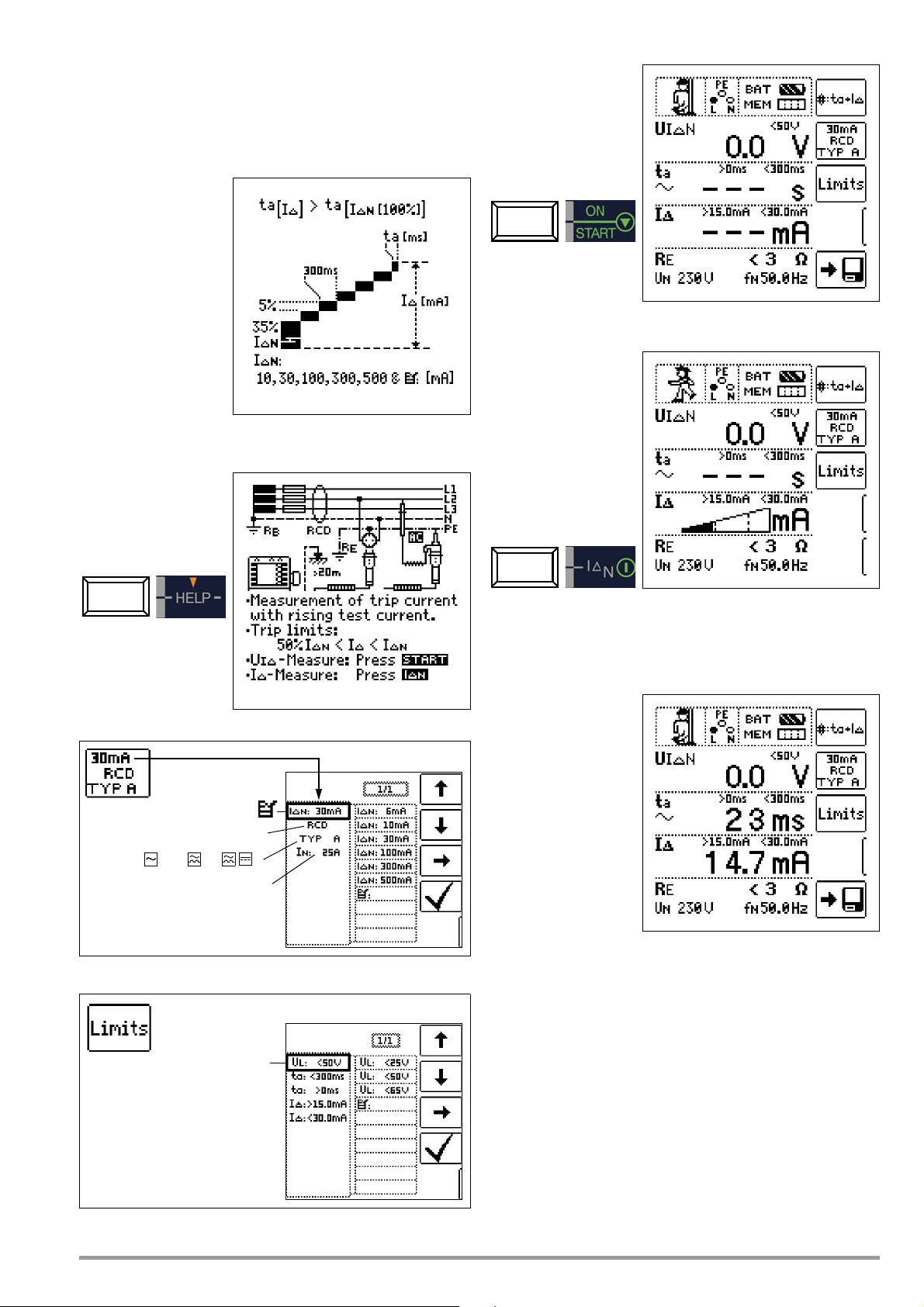
14.7
Nominal residual current:
Type 1 : RCD, SRCD, PRCD etc.
Nominal current: 6 ... 125 A
Type 2 : AC , A/F , B *
* Type B = AC/DC sensitive
10 ... 500 mA
Contact voltage:
< 25 V, < 50 V, < 65 V
Intelligent Ramp – ta+IΔ Function (PROFITEST MXTRA only)
14.7.1 Applications
The advantage of this measuring function in contrast to individual
measurement of I
breaking time and breaking current by means of a test current
which is increased in steps, during which the RCD is tripped only
once.
The intelligent ramp is
subdivided into time
segments of 300 ms
each between the initial
current value (35% I
and the final current
value (130% IΔN). This
results in a gradation for
which each step corresponds to a constant
test current which is
applied for no longer
than 300 ms, assuming
that tripping does not
occur.
And thus both tripping
current and tripping time are measured and displayed.
and tA is the simultaneous measurement of
ΔN
)
ΔN
Connection
Start Contact Voltage Measurement
Start Tripping Test
Set Parameters
The measurement sequence can be broken off prematurely at
any time by pressing the ON/START key.
Measurement Results
GMC-I Messtechnik GmbH 59
Page 60

14.8 Testing Residual Current Monitors
Nom. res. current: 10 ... 500 mA
Waveform:
Nominal current: 6 ... 125 A
Type : A , B *
* Type B = AC/DC sensitive
X times tripping current:
Connection: without/with probe
System type: TN/TT, IT
Contact voltage:
< 25 V, < 50 V, < 65 V
– RCM Function (PROFITEST MXTRA only)
General
Residual current monitors (RCMs) monitor residual current in elec-
trical systems and display it continuously. As is also the case with
residual current devices, external switching devices can be controlled in order to shut down supply power in the event that a
specified residual current value is exceeded.
However, the advantage of an RCM is that
the user is informed of
fault current within the
system before shutdown
takes place.
As opposed to individual
measurement of I
, measurement results
t
A
must be evaluated manually in this case.
If an RCM is used in
combination with an
external switching
device, the combination
must be tested as if it
were an RCD.
ΔN
and
Connection
Measure Contact Voltage
Non-Tripping Test with 1/2 x I
and 10 s
Δ
N
Set Parameters for I
After 10 seconds have passed, no fault current may be signalled.
The measurement must be evaluated afterwards. In the event that
“NOT OK” is selected (in case of false alarm), an error is indicated
by the UL/RL LED which lights up red.
The measured value cannot be saved to memory and included in
the test report until it has been evaluated.
F
Tripping Test with 1 x I
ΔN
– Measurement of Signal Response Time (stopwatch function)
with the Residual Current Generated by the Test Instrument
In order to document the tripping time, the measurement must be
stopped manually with the ON/START or I
the fault current has been signalled.
In the event that “NOT OK” is selected, an error is indicated by the
60 GMC-I Messtechnik GmbH
UL/RL LED which lights up red.
The measured value cannot be saved to memory and included in
the test report until it has been evaluated.
key immediately after
ΔN
Page 61

14.9 Testing the Operating States of Electric Vehicles at
Charging Stations per IEC 61851 (MTECH+ & MXTRA only)
A charging station is an equipment designed for the charging of electric vehicles per IEC 61851which essentially consists of a plug connector, a cable protection, a residual current device (RCD), as well as
a circuit breaker and a security communication system (PWM).
Depending on the place of installation and application, further functional features such as mains connection and meter may be included.
Adapter selection (test box)
Simulation of operating states per IEC 61851with the MENNEKES test box
(Status A – E)
The MENNEKES test box only serves the purpose of simulating dif-
ferent operating states of an electric vehicle fictitiously connected
with a charging station. The settings for the simulated operating
states are indicated in the operating instructions for the test box.
Status C – Non-gassing vehicle identified
• Readiness for charging on the vehicle/power side is activated,
• Voltage between PE and CP is +6 V / –12 V.
Status D – Gassing vehicle identified
• Readiness for charging on the vehicle/power side is activated,
• Voltage between PE and CP is +3 V / –12 V.
The simulated operating states can be stored in the MTECH+ or
MXTRA as visual inspection and documented in the ETC software.
The operating state (status) to be tested is selected with the
SECLECT STATUS key at the MTECH+ or MXTRA test instrument.
Status A – Charging conductor only connected with charging point
• CP signal is switched on,
• voltage between PE and CP is 12 V.
Status B – Charging conductor connected with charging point and
vehicle
• the charging conductor is locked at the charging point and in
the vehicle,
• vehicle not yet ready for charging,
• voltage between PE and CP is +9 V / –12 V.
Status E – Conductor is damaged
• Short circuit between PE and CP,
• Charging conductor is unlocked at the charging point,
• Voltage between PE and CP is +0 V.
Semi-automatic changing between operating states
As an alternative to the manual
changing between operating
states via the parameter menu
of the SECLECT STATUS softkey
at the test instrument, there is
another fast and convenient
way of changing between the
operating states: select status
parameter AUTO. Each time
after replying to and storing a
visual inspection, an automatic
changeover to the next state
takes place, with the keys
shown on the display corresponding to 01/05 A/E (01 = A, 02 = B, 03 = C, 04 = D, 05 = E).
It is possible to skip the status variants by pressing key I
test instrument or at the test socket.
ΔN
at the
GMC-I Messtechnik GmbH 61
Page 62

14.10 Test Sequences for Report Generation of Fault Simulations
Attention!
!
on PRCDs with PROFITEST PRCD
The following functions can be performed when the
PROFITEST MXTRA test instrument is connected with the PROFITEST
PRCD test adapter:
• Three test sequences are preconfigured:
– PRCD-S (single phase/3-pole)
– PRCD-K (single phase/3-pole)
– PRCD-S (three-phase/5-pole)
• The test instrument guides you through all test steps in a
semi-automatic fashion:
Single phase PRCDs:
– PRCD-S: 11 test steps
– PRCD-K: 4 test steps
3-phase PRCDs:
– PRCD-S: 18 test steps
• Each test step is assessed and evaluated by the user (OK/not
OK) for subsequent report generation purposes.
• Measurement of protective conductor resistance of the PRCD
by means of function R
that the protective conductor measurement represents a
modified RLO measurement with ramp curve for PRCDs, see
section 12.
• Measurement of insulation resistance of the PRCD by means
of function R
• Trip test with nominal fault current by means of function I
at the test instrument, see section 7.3.
• Measurement of tripping time by means of function I
test instrument, see section 7.3.
• Varistor test with PRCD-K: measurement via ISO ramp, see
section 11.
at the test instrument, see section 11.
INS
at the test instrument. Please note
LO
Adapter (MXTRA only)
at the
ΔN
F
14.10.2 Parameter Settings
Meaning of Symbols for the Respective Fault Simulation
Switch
Position
PROFITEST PRCD
PE-U
—AUTOAUTO
Symbols shown at
PROFITEST MXTRA
Parameter
Setting
ON 1~ON
ON 3~ON
BREAK Lx
Lx <-> PE
Lx <-> N
Uext -> PE
EXT
PROBE
PRCD-Ip
Meaning of Symbols
Menu
Display
Activate single phase PRCD
Activate 3-phase PRCD
Disconnection of conductor
Conductor exchange between
phase conductor and PE or
neutral conductor
PE to phase
Contact key ON at PRCD with
probe
Protective conductor current
measurement with current
clamp transformer
Semi-automatic changing of
fault simulations
Parameter PRCD-S single phase – 11 parameters = 11 test steps
Together with the required intermediate steps for PRCD activation
(=ON), the parameters for the fault simulations represent die 11
potential test steps:
Interruption (BREAK...), conductor exchange (L1 <-> PE),
PE to phase (Uext -> PE), contacting of key ON, protective conductor current measurement (Figure on the right: PRCD-Ip) .
It is imperative that you read the operating instructions
for PROFITEST PRCD before connecting the
PROFITEST MXTRA with the PRCD adapter.
14.10.1 Selecting the PRCD under Test
Parameter PRCD-S 3-phase – 18 parameters = 18 test steps
Parameter PRCD-K single phase – 5 parameters = 5 test steps
62 GMC-I Messtechnik GmbH
Page 63

14.10.3 Test Sequence PRCD-S (single phase) – 11 Test Steps
Selection Examples
Simulation Interruption (Steps 1 to 6)
Simulation Conductor Exchange (Step 7)
Selection Examples
Simulation Interruption (Steps 1 to 10)
Simulation Conductor Exchange (Steps 11 to 16)
Simulation PE to Phase (Step 8)
Contacting Key ON at PRCD with Probe (Step 10)
Measurement of Protective Conductor Current with a Current
Clamp Transformer (Step 11)
14.10.4 Test Sequence PRCD-S (three-phase) – 18 Test Steps
Simulation PE to Phase (Step 17)
Measurement of Protective Conductor Current with Current Clamp
Transformer (Step 18)
Semi-automatic Change of Fault Simulations (Statuses)
As an alternative to changing
manually between the fault simulations via the parameter menu
of the respective PRCD selection PRCD-S 1~, PRCD-K 1~ or
PRCD-S 3~ at the test instrument, it is possible to switch
quickly and conveniently
between the fault simulations.
Select status parameter AUTO
for this purpose. After replying
to and storing each visual
inspection, an automatic
switch-over to the next fault simulation takes place. Individual fault
simulations can be skipped by pressing key I
ment or at the test plug.
at the test instru-
ΔN
GMC-I Messtechnik GmbH 63
Page 64

15 Automatic Test Sequences – AUTO Function
Note
1 2 3 4
5 6 7
8
109
11 12
Verwendetes Prüfgerät
auswählen!
!
If the same order of tests with subsequent report generation is to
be performed repeatedly, as is, for example, specified by certain
standards, we recommend using test sequences.
With the help of test sequences it is possible to compile automatic test procedures on the basis of the manual individual measurements. A test sequence consists of up to 200 individual test
steps which have to be processed one after the other.
Basically, a distinction is made between three types of individual
steps:
• Note: the test procedure is interrupted by a pop-up note for
the test engineer. It is not continued before the test engineer
acknowledges the note.
Example: Note prior to insulation resistance measurement:
„Disconnect the device from the mains!“
• Visual inspection, testing and report: the test procedure is interrupted by a pop-up window of a passed/failed evaluation,
comments on and results of the evaluation are saved in the
database.
• Measurement: Measurement like the individual measurements
performed by the test instruments with data storage and
parameter configuration.
The test sequences are created at a PC by means of the ETC
software and are then transferred to the test instruments.
The measurement parameters are also configured at a PC. However, they can still be modified at the test instrument during the
test procedure before the respective measurement is launched.
After restarting the test step, the parameter settings defined in
ETC are loaded.
The parameters are not subjected to a plausibility check
by the ETC software. We therefore advise you to test the
newly created test sequence at the test instrument before
filing it permanently in your database.
Step-by-step Overview: Generating Test Sequences at the PC
1 Generate new test sequence – enter denomination
2 Change denomination of the selected test sequence
3 Duplicate selected test sequence,
(copy) is added at the end of the duplicated name
4 Delete selected test sequence
5 Generate and/or add new test step for selected test sequence
– Choose the type of test step from the list and accept or modify the
denomination
6 Duplicate selected test step
7 Delete selected test step
8 Change the order of the selected test steps
9 Select measuring parameters for the selected type of test step from the list
10 Choose the setting for the measuring parameters from the list
11 Accept modification for the measuring parameter
12 Close test sequence menu
Limit values are currently not defined in ETC, but have to be
adjusted during the automatic test sequence.
Menu for the Processing of Test Sequences
In order to process existing test sequences, to add, for example,
further test sequences or to adjust parameter settings, they have
to be loaded to the ETC PC software beforehand.
There are two possibilities to do this:
•ETC: Extras → Test sequences → Load test sequences
(from file „pruefsequenzenxyz.seq“)
or
• ETC: Device → Test sequences → Receive test sequences
(from the connected test instrument PROFITEST MPRO or
PROFITEST MXTRA)
Saving Test Sequences to the ETC Software at the PC
We recommend saving the test sequences of the default setting,
modified as well as newly created test sequences via command
„Extras → Test sequences → Save test sequences“ to the PC or
other storage media under a file name (testsequencesxyz.seq).
This helps to prevent data loss as a result of certain administrative
operations, see the following remarks.
As a maximum of 10 test sequences can be transferred to the
test instrument, it is not possible to save more than 10 test
sequences in one file.
Via command „Extras → Test sequences → Load test
sequences“ the test sequences saved to a file can be reloaded to
the ETC software at any time.
For subsequent processing select command
„Extras → Test sequences → Edit test sequences“.
Please note that the active test sequences in the ETC software are
deleted by the following operations:
• by receiving test sequences from the test instrument
(ETC: Device → Test sequences → Receive test sequences)
• by changing the user language (ETC: Language → ...)
• by saving the data from the test instrument
(ETC: Device → Backup/Restore → Backup)
64 GMC-I Messtechnik GmbH
Page 65

Please note that the test sequences loaded to the test instrument
AUTO
are deleted by the following operations in the test instrument:
• by receiving selection lists from the PC
(ETC: Device → Selection lists → Transmit selection lists)
• by receiving new test sequences from the PC
(ETC: Device → Test sequences → Send test sequences)
• by transmitting the saved data to the test instrument
(ETC: Device → Backup/Restore → Restore)
• by resetting to default settings
(Switch position SETUP → key GOME SETTING)
• by firmware updates
• by changing the user language
(Swith position SETUP → key CULTURE)
• by deleting the entire database in the test instrument
Selecting and Starting a Test Sequence at the Test Instrument
Figure 15.1
Transferring Test Sequences from the PC to the Test Instrument
After activating the ETC command „Device → Test sequences →
Send test sequences“ all test sequences that have been created
(maximum of 10) are transferred to the connected test instrument.
During the transfer of the
test sequences the
above progress bargraph is shown at the
PC screen and the
righthand image
appears on the display
of the test instrument.
After the data transfer
has been completed,
the display switches to
the storage menu „database“.
By pressing ESC you
proceed to the measurement menu display of the current switch position.
Selecting Switch Position AUTO at the Test Instrument
Press the START key to launch the selected test sequence (here:
SEQU.1).
When executing a test step of the measurement type, the display
structure known from the individual measurements is shown.
Instead of the storage and battery symbol, the current test step
number is shown in the header (here: step 01 of 06), see figure
15.2. The next test step is shown after pressing the „Save“ key
twice.
Setting Parameters and Limit Values
Parameters and limit values can also be modified while performing
a test sequence or before starting the measurement. This modification only affects the active test procedure and is not saved.
Skipping of Test Steps
There are two possibilities to skip test steps and/or individual
measurements:
• Activate test sequence, switch to the right-hand test step column with the cursor, select the x
START.
• Within a test sequence, the navigation menu is activated by pressing the navigation key Cursor leftright. Switch to the previous or
next test step with the cursors
which are now displayed separately.
Leave the navigation menu and reactivate the current test step
with ESC.
th
test step and press key
Interrupt or Abort a Test Sequence
An active sequence is aborted with ESC and subsequent confirmation.
When the last test step is completed, the message „Sequence
completed“ is shown. After confirming this message, the start
menu „List of test sequences“ appears on the display.
Figure 15.2
When the rotary switch is set to AUTO, all existing test sequenes
in the instrument are displayed, see figure 15.1.
If there are no test sequences in the instrument, message „NO
DATA“ appears.
GMC-I Messtechnik GmbH 65
Page 66

16 Database
16.1 Creating Distributor Structures, General
A complete distributor structure with data for electrical circuits
and RCDs can be created in the PROFITEST MASTER test instru-
ment.
This structure makes it possible to assign measurements to the
electrical circuits of various distributors, buildings and customers.
There are two possible procedures:
• On location or at the
construction site:
Create the distributor
structure in the test
instrument.
A distributor structure with up to
50,000 structural
elements can be
created in the test
instrument, which is
saved to the instrument’s flash memory.
or
• Create and save an image of an existing distributor structure
at a PC with the help of ETC report generating software (Electric
Testing Center) (see condensed operating instructions for ETC
report generating software). The distributor structure is then
transferred to the test instrument.
16.2 Transferring Distributor Structures
The following data transfer operations are possible:
• Transfer a distributor structure from the PC to the test instrument.
• Transfer a distributor structure including measured values
from the test instrument to the PC.
The test instrument and
the PC must be connected with a USB cable
in order to transfer distributor structures and
data.
The following image
appears at the display
during transfer of structures and data.
16.3 Creating a Distributor Structure in the Test Instrument
Overview of the Meanings of Icons used to Create Structures
Icon Meaning
Main
Sub-
Level
Level
Memory menu, page 1 of 3
Cursor UP: scroll up
Note regarding ETC Report Generating Software
The following steps must be completed before using the software:
• Install USB device drivers:
(required for operation of PROFITEST MASTER with a PC)
GMC-I Driver Control software can be downloaded from
Gossen Metrawatt's website at:
http://www.gossenmetrawatt.com
→ Products → Software → Software for Testers
→ Utilities → Driver Control
• Install ETC report generating software:
You can download the current ETC version free of charge from
our homepage under section mygmc after registration or login:
http://www.gossenmetrawatt.com
→ Products → Software → Software for Testers
→
Protocol Software without Database →
ETC → myGMC → zum Login
Cursor DOWN: scroll down
ENTER: acknowledge selection
+ → – change to sub-level
(open directory) or
– → + change to main level
(close directory)
Display of complete structure designation (max.
63 characters) or ID number (max. 25 characters)
in a zoom window
Temporarily switching back and forth between
structure designation and ID number.
These keys do not interfere with the main configuration in the setup menu, see DB MODE on
page 11.
Hide structure designation or ID number
Change display to menu selection
Memory menu, page 2 of 3
Add a structural element
Meaning of icons from top to bottom:
Customer, building, distributor, RCD, electrical cir-
cuit, operating equipment, machine and earth
electrode (display of the icons depends on the
selected structural element).
Selection: UP/DOWN scroll keys and ↵
In order to add a designation to the selected
structural element, refer to edit menu in following
column.
EDIT
For additional icons see edit menu below
Delete the selected structural element.
66 GMC-I Messtechnik GmbH
Page 67

Icon Meaning
Distributor
A check mark to the right of a structural element means that all measurements
within the respective hierarchy have been passed.
Smbol x: at least one measurement has not been passed.
No symbol: Measurement has not yet been performed.
Building
Customer
RCDs
Electr. circuit
Equipment
Same type of element as in the Windows Explorer:
+: sub-object available, display by pressing ↵.
–: sub-objects are displayed, hide by pressing ↵.
Equipment
Scroll up
Scroll down
Acknowledge selection /
Display object
Next page
change level
or ID number
Create object
Delete object
VΩA: show measurement data
Edit designation
Show measurement data, if a measurement has
been performed for this structural element.
Edit the selected structural element.
Memory menu, page 3 of 3
Search for ID number.
> Enter complete ID number.
Search for text.
> Enter full text (complete word).
Search for ID number or text.
Continue searching.
Edit menu
Cursor LEFT:
Select an alphanumeric character
Cursor RIGHT:
Select an alphanumeric character
ENTER: accept an individual character
Acknowledge entry
←
Cursor left
→
Cursor right
Delete characters
Distributor Structure Symbology / Tree Structure
16.3.1 Creating Structures (example for electrical circuit)
After selection with the MEM key, all setting options for the creation of a tree structure are made available on three menu pages
(1/3, 2/3 and 3/3). The tree structure consists of structural elements, referred to below as objects.
Select the position at which a new object will be added.
Switching amongst different types of alphanumeric characters:
A Upper case letters
a Lower case letters
0Numbers
@ Special characters
GMC-I Messtechnik GmbH 67
Use the ↑↓ keys in order to select structural elements.
Change to the sub-level with the ↵ key.
Go to the next page with the >> key
Create a new object.
Press the key in order to create a new object.
Page 68

Select a new object from a list.
Note
Note
Scroll up
Scroll down
Acknowledge selection
Select character
Select character
↵ Accept character
Delete characters
Character selection:
✓ Save object designation
A, a, 0, @
Select parameter
→ List of parameter settings
Acknowledge parameter selection
↵ Acknowledge parameter setting
and return to page 1/3
Select parameter setting
in the database menu.
Scroll up
Scroll down
Acknowledge selection /
Display object
Menu selection → page 3/3
change level
or ID number
Search for ID number
Search for text
Search for ID number or text
Select character
Select character
↵ Accept character
Delete characters
Character selection:
✓ Save object designation
Continue searching
Select the desired object from the list with the ↑↓ keys and
acknowledge with the ↵ key.
Depending upon the profile selected in the test instrument’s
SETUP menu (see section 4.6), the number of object types may
be limited, and the hierarchy may be laid out differently.
Enter a designation.
16.3.2 Searching for Structural Elements
The search always starts with database, regardless of the currently
marked object.
Go to page 3/3 in the database menu.
After selecting text search
Enter a designation and then acknowledge it by entering a ✓.
Acknowledge the standard or adjusted parameters
shown below, because the created designation will otherwise not be accepted and saved.
Set Electrical Circuit Parameters
and entering the desired text (only full matches are found – no
wild cards, case sensitive)
For example, nominal current values must be entered here for the
selected electrical circuit. Measuring parameters which have been
accepted and saved in this way are subsequently accepted by
the current measuring menu automatically when the display is
switched from the structural view to measurement.
Electrical circuit parameters changed during structure
creation are also retained for individual measurements
(measurement without saving data).
If you change the electrical circuit parameters defined in the
structure of the test instrument, a warning is issued upon
saving, see error message on page 81.
68 GMC-I Messtechnik GmbH
the first match is displayed.
Further matches can be found by selecting
the icon shown at the right.
Page 69

If no further matches are found, the message shown above is dis-
Note
Note
Search for ID number
Search for text
End search
Search for ID number or text
played.
16.4 Saving Data and Generating Reports
Preparing and Executing a Measurement
Measurements can be performed and stored to memory for each
structural element. Proceed as follows, adhering to the prescribed
sequence:
➭ Select the desired measurement with the rotary knob.
➭ Start the measurement by pressing the ON/START or IΔ
Upon completion of measurement, the “→ Floppy Disk” softkey is
displayed.
➭ Briefly press the “Save Value” key.
key.
N
If you change the parameters in the measurement view,
they are not saved for the structural element. A measurement with changed parameters can nevertheless be
saved to the structural element, and any changed parameters are documented in the report for each measurement.
Retrieving Saved Measured Values
➭ Switch the display to the distributor structure by pressing the
MEM key and select the desired electrical circuit with the scroll
keys.
➭ Switch to page 2
by pressing the key shown here:
➭ Display the measurement data
by pressing the key shown here:
One measurement with date
and time, as well as any comment you might have entered, is
displayed in each screen.
Example:
RCD Measurement
The display is switched to the memory menu or the
structural view.
➭ Navigate to the desired memory location, i.e. to the desired
structural element / object, for which the measurement data
will be saved.
➭ If you would like to save a comment along with the
measurement, press the key shown at the right and
enter a designation via the “EDIT” menu as described in
section 16.3.1.
➭ Complete data storage by pressing the “STORE” key.
Storage of Error Messages (Pop-ups)
If a measurement is completed without a measured value being
produced on account of an error, this measurement can be saved
to memory along with the pop-up via the „Save Value“ key. In the
ETC the corresponding text is given out instead of the pop-up
smybol. This only applies to a limited selection of pop-ups, see
below. In the database of the test instrument, neither the symbol
nor the text can be retrieved.
A check mark in the header means that the respective
measurement has been passed.
An X means that the measurement has not been passed.
➭ Scrolling amongst measurements
is possible with the keys shown here:
➭ The measurement can be deleted with the key
shown here:
A prompt window asks you to confirm deletion.
With the help of the key shown at the right (MW: measured value / PA: parameter), the setting parameters
can be displayed for this measurement.
Alternative Storage Procedure
➭ The measured value can be saved to the last se-
lected object in the structural diagram by pressing
and holding the “Save Value” key, without switching
the display to the memory menu.
GMC-I Messtechnik GmbH 69
➭ Scrolling amongst measurements
is possible with the keys shown here:
Page 70

Data Evaluation and Report Generation with ETC Software
Note
Note
All data, including the distributor structure, can be transferred to
the PC and evaluated with the help of ETC software. Additional
information can be entered here subsequently for the individual
measurements. After pressing the appropriate key, a report
including all measurements within a given distributor structure is
generated, or the data are exported to an Excel spreadsheet.
The database is exited when the rotary selector switch is
turned. Previously selected parameters in the database
are not used for the measurement.
16.4.1 Use of Barcode Scanners and RFID Readers
Search for an Already Scanned Barcode
The search can be started from any switch setting and menu.
➭ Scan the object’s barcode.
The found barcode is displayed inversely.
➭ This value is accepted after pressing the ENTER key.
A previously selected object is not taken into consideration by the search.
Continued Searching in General
Regardless of whether or not an object has been found,
searching can be continued by pressing this key:
– Object found: Searching is continued underneath the pre-
viously selected object.
– No further object found: The entire database is searched
at all levels.
Reading In a Barcode for Editing
If the menu for alphanumeric entry is active, any value scanned by
means of a barcode or RFID reader is accepted directly.
Using a Barcode Printer (accessory)
A barcode printer allows for the following applications:
• Read-out of ID numbers encrypted as barcodes; for quick
and convenient acquisition for periodic testing
• Read-out of repeatedly occurring designations such as test
object types encrypted as barcodes in a list, allowing them to
be read in as required for comments.
70 GMC-I Messtechnik GmbH
Page 71

17 Operating and Display Elements
Attention!
!
Attention!
!
Attention!
!
Note
(7) Alligator Clip (plug-on)
Test Instrument and Adapter
(1) Control Panel – Display Panel
The following are displayed at the LCD:
• One or two measurement values as three place numeric display with unit of measure and abbreviated measured quantity
• Nominal values for voltage and frequency
• Circuit diagrams
• On-line help
• Messages and instructions
The display and control panel can be swiveled forward or backward with the detented swivel hinge. The instrument can thus be
set to the optimum reading angle.
(2) Eyelets for the Shoulder Strap
The included shoulder strap can be attached at the right and left
hand sides of the instrument. You can hang the instrument from
your shoulder and keep both hands free for measurement.
(3) Rotary Selector Switch
The following basic functions can be selected with this rotary
switch:
SETUP / IΔN / IF / Z
SOR / EXTRA / AUTO
The various basic functions are selected by turning the function
selector switch while the instrument is switched on.
(4) Measuring Adapter
The measuring adapter (2-pole) may only be used together with the test instrument’s test plug.
Use for other purposes is prohibited!
The plug-on measuring adapter (2-pole) with the two test probes
is used for measurements in systems without earthing contact
outlets, e.g. at permanent installations, distribution cabinets and
all three-phase outlets, as well as for insulation resistance and
low-value resistance measurements.
The 2-pole measuring adapter can be expanded to three poles for
phase sequence testing with the included measurement cable
(test probe).
(5) Plug Insert (country-specific)
L-P E
/ Z
L-N
/ RE / R
LO
/ R
ISO
(R
/ U / SEN-
INS)
(8) Test Probes
The test probes comprise the second (permanently attached) and
third (plug-on) poles of the measuring adapter. A coil cable connects them to the plug-on portion of the measuring adapter.
(9) ON/Start
▼ Key
The measuring sequence for the function selected in the menu is started by
pressing this key, either on the test
plug or at the control panel. Exception: If the instrument is
switched off, it can only be switched on by pressing the key at the
control panel.
This key has the same function as the
(10) I
/ I Key (at the control panel)
ΔN
▼ key on the test plug.
The following sequences are triggered
by pressing this key, either on the test
plug or at the control panel:
• Starts the tripping test after measurement of contact voltage
for RCCB testing (I
• Measurement of R
).
ΔN
OFFSET is started within the R
LO
/ Z
function.
L-N
• Semiautomatic polarity reversal (see section 5.8)
(11) Contact “Surfaces
The contact surfaces are located at both sides of the test plug.
When the contact plug is grasped in the hand, contact is automatically made with these surfaces. The contact surfaces are electrically isolated from the terminals and from the measuring circuit.
When the rotary switch is set to the “U” position, the instrument
can be used as a phase tester for protection class II devices!
In the event of a potential difference of greater than 25 V between
protective conductor terminal PE and the contact surface, PE is
displayed (see also section 18, “LED Indications, Mains Connections and Potential Differences”, beginning on page 73).
(12) Test Plug Holder
The test plug with attached plug insert can be reliably secured to
the instrument with the rubberized holder.
(13) Fuses
The two fuses protect the instrument against overload. Phase
conductor L and neutral conductor N are fused individually. If a
fuse is defective, and if an attempt is made to perform a measurement which uses the circuit protected by this fuse, a corresponding message appears at the display panel.
The plug insert may only be used together with the test
instrument’s test plug.
Use for other purposes is prohibited!
After the plug insert has been attached, the instrument can be
Severe damage to the instrument may occur if incorrect
fuses are used.
Only original fuses from GMC-I Messtechnik GmbH assure required protection by means of suitable blowing
characteristics, see section 20.3.
directly connected to earthing contact outlets. You need not concern yourself with poling at the plug. The instrument detects the
positions of phase conductor L and neutral conductor N and
automatically reverses polarity if necessary.
The instrument automatically determines whether or not both pro-
The voltage ranges remain functional even if fuses have
blown.
tective contacts in the earthing contact outlet are connected to
one another, as well as to the system protective conductor, for all
(14) Holders for Test Probes (8)
types of protective conductor measurements when the plug insert
is attached to the test plug.
(15/16) Current Clamp Sockets
Only the current clamp transformers offered as accessories may
(6) Test Plug
be connected to these sockets.
The various country specific plug inserts (e.g. protective contact
plug insert for Germany or SEV plug insert for Switzerland) or the
measuring adapter (2-pole) are attached to the test plug and
secured with a threaded connector.
The controls on the test plug are subject to interference suppression filtering. This may lead to slightly delayed responses as
opposed to controls located directly on the instrument.
(17) Probe Connector Socket
The probe connector socket is required for the measurement of
probe voltage U
tance R
and standing surface insulation resistance.
E
, earth electrode voltage UE, earthing resis-
S-PE
It can be used for the measurement of contact voltage during
RCD testing. The probe is connected with a 4 mm contact pro-
tected plug.
GMC-I Messtechnik GmbH 71
Page 72

The instrument determines whether or not the probe has been
Attention!
!
Attention!
!
properly set and displays results at the display panel.
(18) USB Port
The USB port allows for the exchange of data between the test
instrument and a PC.
(19) RS 232 Port
This connection allows for data entry by means of a barcode
scanner or an RFID reader.
(20) Charging Socket
This socket may only be used to connect the Z502R charger for
recharging batteries in the instrument.
(21) Battery Compartment Lid – Replacement Fuses
Control Panel – LEDs
MAINS/NETZ LED
This LED is only functional when the instrument is switched on. It
has no function in voltage ranges U
It lights up green, red or orange, or blinks green or red depending
upon how the instrument has been connected and the selected
function (see also section 18, “LED Indications, Mains Connections and Potential Differences”, beginning on page 73).
This LED also lights up if line voltage is present during measurement of R
UL/RL LED
This LED lights up red if contact voltage is greater than 25 V or
50 V during RCD testing, as well as after safety shut-down
occurs. It also lights up if R
exceeded or fallen short of.
and RLO.
INS
or RLO limit values have been
INS
L-N
and U
L-P E
.
When the lid is removed, the instrument must be disconnected from the measuring circuit at all poles!
The battery compartment lid covers the Compact Master Battery
Pack (Z502H) or a battery holder with the batteries and the
replacement fuses.
The battery holder or the Z502H battery pack is designed for use
with eight 1.5 V AA batteries in accordance with IEC LR 6 for
power supply to the instrument. When inserting batteries, make
sure that they are poled in accordance with the symbols.
Make sure that all of the batteries are inserted with correct polarity. If just one battery is inserted with reversed
polarity, it will not be recognized by the instrument and
may result in leakage from the batteries.
Two replacement fuses are located beneath the battery compartment lid.
RCD • FI LED
This LED lights up red if the RCCB is not tripped within 400 ms
(1000 ms for type RCD S selective RCDs) during the tripping test
with nominal residual current. It also lights up if the RCCB is not
tripped before nominal residual current has been reached during
measurement with rising residual current.
72 GMC-I Messtechnik GmbH
Page 73

18 LED Indications, Mains Connections and Potential Differences
???
NPEL
NPEL
NPEL
NPELxNPELxNPEL
x
NPEL
NPEL
x
NPEL
Status
LED Indications
NETZ/
MAINS
NETZ/
MAINS
NETZ/
MAINS
NETZ/
MAINS
NETZ/
MAINS
NETZ/
MAINS
UL/R
FI/RCD
L
Lights up
green
Blinks
green
Lights up
orange
Blinks red
Lights up
red
Blinks Yel-
low
Lights up
red
Lights up
red
Tes t
plug
Meas.
Adapter
X
X
X
XX
XR
X
XX
XX
Position of the
Function Switch
I
/ IF
ΔN
Z
/ Z
L-P E
I
/ IF
ΔN
/ Z
L-P E
I
/ IF
ΔN
/ Z
L-P E
I
/ IF
ΔN
/ Z
L-P E
/ R
INS
I
/ IF
ΔN
/ Z
L-P E
I
ΔN
/ R
INS
I
/ IF
ΔN
int. ramp
/ R
/ R
/ R
/ R
LO
/ R
LO
L-N
ΔU, ZST, kWh, IMD,
int. ramp, RCM
Z
L-N
ΔU, ZST, kWh, IMD,
int. ramp, RCM
Z
L-N
Z
L-N
ΔU, ZST, kWh, IMD,
int. ramp, RCM
Z
L-N
R
Function / Meaning
Correct connection, measurement enabled
E
N conductor not connected,
measurement enabled
E
Line voltage of 65 V to 253 V to PE, 2 different phases active (no N conductor at mains), measurement enabled
E
1) No line voltage or
2) PE interrupted
E
Interference voltage detected, measurement disabled
L and N are connected to the phase conductors.
E
– Contact voltage U
– Safety shut-down has occurred
– Limit value exceeded or fallen short of for R
The RCCB was not tripped, or was tripped too late during the tripping
test.
and UIΔ >25V respectively >50V
IΔN
/ RLO function
INS
Mains Connection Test — Single-Phase System — LCD Connection Pictographs
is displayed
is displayed
is displayed
is displayed
is displayed
is displayed
is displayed
is displayed
All except for U No connection detected
All except for U Connection OK
All except for U L and N reversed, neutral conductor charged with phase voltage
All except for U and RE
No mains connection
RE Standard display without connection messages
All except for U Neutral conductor interrupted
Protective conductor PE interrupted,
All except for U
neutral conductor N and/or phase conductor L charged with phase voltage
All except for U
Phase conductor L interrupted,
neutral conductor N charged with phase voltage
All except for U Phase conductor L and protective conductor PE reversed
is displayed
is displayed
GMC-I Messtechnik GmbH 73
All except for U
All except for U L and N are connected to the phase conductors.
Phase conductor L and protective conductor PE reversed
Neutral conductor interrupted (with probe only)
Page 74

Status
NPEL
Tes t
plug
Meas.
Adapter
Position of the
Function Switch
Function / Meaning
Mains Connection Test — 3-Phase System — LCD Connection Pictographs
is dis-
played
is dis-
played
is dis-
played
is dis-
played
is dis-
played
is dis-
played
is dis-
played
is dis-
played
is dis-
played
U
(3-phase measurement)
U
(3-phase measurement)
U
(3-phase measurement)
U
(3-phase measurement)
U
(3-phase measurement)
U
(3-phase measurement)
U
(3-phase measurement)
U
(3-phase measurement)
U
(3-phase measurement)
Clockwise rotation
Counter-clockwise rotation
Short between L1 and L2
Short between L1 and L3
Short between L2 and L3
Conductor L1 missing
Conductor L2 missing
Conductor L3 missing
Conductor L1 to N
is dis-
played
is dis-
played
(3-phase measurement)
(3-phase measurement)
U
U
Connection Test — Earthing resistance (battery operation)
is dis-
played
is dis-
played
is dis-
played
is dis-
played
is dis-
played
is dis-
played
PRO-RE RE
Messza
nge
PRO-RE RE
PRO-RE RE
PRO-RE RE
RE Standard display without connection messages
RE
Conductor L2 to N
Conductor L3 to N
Interference voltage at probe S > 3 V
Restricted measuring accuracy
Interference current/measuring current ratio > 50 at RE(sel), 1000 at RE(2Z)
Restricted measuring accuracy
at RE(sel): Interference current > 0,85 A
or Interference current/measuring current ratio > 100
➭ no measured value, display RE.Z – – –
Probe H not connected or RE.H > 150 kΩ
➭ no measurment, display RE – – –
RE.H > 50 kΩ or
RE.H / RE > 10000
➭ Measured value is displayed, restricted measuring accuracy
Probe S not connected
or RE.S > 150 kΩ
or RE.S x RE.H > 25 MΩ²
➭ no measurment, display RE – – –
RE.S > 50 kΩ or
RE.S / RE > 300
➭ Measured value is displayed, restricted measuring accuracy
Probe E not connected or RE.E > 150 kΩ, RE.E/RE > 2000
➭ no measurment, display RE – – –
RE.E/RE > 300
➭ Measured value is displayed, restricted measuring accuracy
74 GMC-I Messtechnik GmbH
Page 75

Status
PE
PE
Battery Test
Tes t
plug
Meas.
Adapter
Position of the
Function Switch
Function / Meaning
is displayed
All
Rechargeable batteries must be recharged, or replaced towards the end
of their service life (U < 8 V).
PE test by means of finger contact at the contact surfaces on the test plug
LCD LEDs
U
is displayed
is displayed
L/RL
FI/RCD
light up
red
U
L/RL
FI/RCD
light up
red
XX
XX
U
(single-phase
measurement)
U
(single-phase
measurement)
Potential difference ≥ 50 V between finger contact and PE (earth contact)
Frequency f ≥ 50 Hz
If L is correctly contacted and PE is interrupted (Frequency f ≥ 50 Hz)
Error Messages — LCD Pictographs
Potential difference ≥ U
(Frequency f ≥ 50 Hz)
Remedy: inspect PE connection
Note: only when appears: measurement can nevertheless be
started by pressing the start key again.
1) Voltage too high (U > 253 V) for RCD test with direct current
2) U always U > 550 V with 500 mA
3) U > 440 V for I
E
4) U > 253 V for I
5) U > 253 V for measurement with probe
XX
XX
All measurements
with protective
conductor
I
/ IF
ΔN
Z
/ Z
L-P E
/ R
L-N
between finger contact and PE (earth contact)
L
/ IF
ΔN
/ IF with 500 mA
ΔN
XX I
XX Z
XX I
ΔN
ΔN
L-PE
/ I
F
EXTRA → PRCD
X X All except for U
I
/ IF
XX
ΔN
Z
/ Z
L-P E
/ R
L-N
RCD is tripped too early, or is defective.
Remedy: test circuit for bias current
RCD is tripped too early, or is defective.
Remedy: Test with “DC + positive half-wave”.
RCD tripped during contact voltage measurement.
Remedy: Check selected nominal test current.
PRCD has tripped.
Cause: poor contact or defective PRCD
Externally accessible fuse is blown.
The voltage ranges remain functional even if fuses have blown.
Special case, R
blown fuse.
: Interference voltage during measurement may result in a
LO
Remedy: Replace fuse (replacement fuses in battery compartment).
Observe notes regarding fuse replacement in section 20.3!
Frequency out of permissible range
Remedy: inspect mains connection
E
GMC-I Messtechnik GmbH 75
Page 76

Status
Tes t
plug
Meas.
Adapter
Position of the
Function Switch
Function / Meaning
All
XX R
INS
/ R
PRO-RE RE (bat)
X
PRO-RE
PRO-RE/
2
XX
XX R
RE (bat) Probe ES not connected or connected wrong.
RE (bat) Generator current clamp (E-Clip-2) not connected
All measurements
with probe
/ R
INS
LO
LO
Excessive temperature inside the test instrument
Remedy: wait for test instrument to cool down
Interference voltage
Remedy: device under test must be disconnected from all sources of voltage
Interference voltage > 20 V at the probes:
H to E or S to E
no measurement possible
Interference voltage at the probe
Overvoltage or overloading of the measuring voltage generator during
measurement of R
INS
or R
LO
IΔN / IF
Z
/ Z
L-N
XX
ZST, RST, R
L-P E
E
Meter start-up
XX All
XX R
XR
LO
LO
XEXTRA → ΔU
XEXTRA → ΔU
No mains connection
Remedy: inspect mains connection
Defective hardware
Remedy:
1) Switch on and off.
or
2) Briefly remove the batteries.
If error message persists, send instrument to GMC-I Service GmbH.
OFFSET measurement is not sensible.
Remedy: Check system.
OFFSET measurement of RLO+ and RLO– is still possible.
R
OFFSET
> 10 Ω:
OFFSET measurement is not sensible.
Remedy: Check system.
Z > 10 Ω:
OFFSET measurement is not sensible.
Remedy: Check system.
ΔU
OFFSET
> ΔU:
Offset value is larger than the measured value at the consuming system.
OFFSET measurement is not sensible.
Remedy: Check system.
Contact problem or blown fuse
XXR
/ RLO / R
INS
Remedy: Check test plug or measuring adapter for correct seating in the
E(bat)
test plug, or replace the fuse.
76 GMC-I Messtechnik GmbH
Page 77
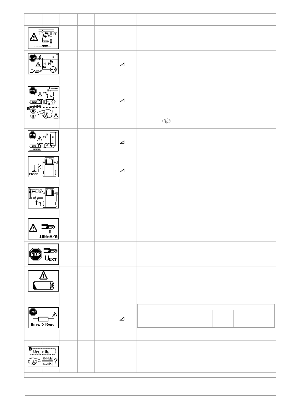
Status
IΔN/I
F
10 mA 30 mA 100 mA 300 mA 500 mA
R
MAX
for I
ΔN
510 Ω 170 Ω 50 Ω 15 Ω 9 Ω
R
MAX
for I
F
410 Ω 140 Ω 40 Ω 12 Ω 7 Ω
Tes t
plug
Meas.
Adapter
Position of the
Function Switch
Function / Meaning
XREThe polarity of the 2-pole adapter must be reversed.
XI
/ IF N and PE are swapped.
ΔN
1) Mains connection error
or
2) Display in the connection pictograph: PE interrupted (x) or
E
XX
I
/ IF
ΔN
Z
/ Z
L-PE
/ R
L-N
Note: only if appears: Measurement can nevertheless be started by
pressing the start key again.
Display at the connection pictograph:
Overlying protective conductor bar interrupted with reference to the keys
XI
ΔN
/ IF
at the test plug
Cause: current measuring path interrupted
Result: no measured value display
I
ΔN
R
E
/ IF
Probe is not detected, probe not connected
Remedy: inspect probe connection
Clamp is not detected:
– Clamp is not connected or
– Current through clamp is too small (partial earth resistance too high) or
R
E
– Transformation ratio set incorrectly
Remedy: Check clamp connection and transformation ratio.
Remedy: Inspect mains connection.
underlying protective conductor bar interrupted with reference to the
keys at the test plug
Cause: voltage measuring path interrupted
Result: measurement is disabled
Check the batteries in the METRAFLEX P300 and replace
if necessary.
I
Z
ΔN
L-P E
RE
R
E
All
/ IF
, R
If you have changed the transformation ratio at the test instrument, a
message appears prompting you to change the setting at the current
clamp sensor as well.
Voltage too high at clamp input or signal distorted
The transformation ratio parameter selected at the test instrument might
not correspond to the transformation ratio at the current clamp sensor.
Remedy: Check transformation ratio or setup.
Battery voltage is less than or equal to 8 V.
Reliable measurement is no longer possible.
Storage of measured values to memory is disabled.
Remedy: Rechargeable batteries must be recharged, or replaced towards
the end of their service life.
Resistance in N-PE path is too high.
Consequence: Required test current cannot be generated, measurement
is aborted.
Upon exceeding the specified contact voltage UL:
Z
and RE: request to switch to the 15 mA wave
E
L-P E
only R
Request to reduce the measuring range (reduce current)
alternatively:
E
GMC-I Messtechnik GmbH 77
Page 78
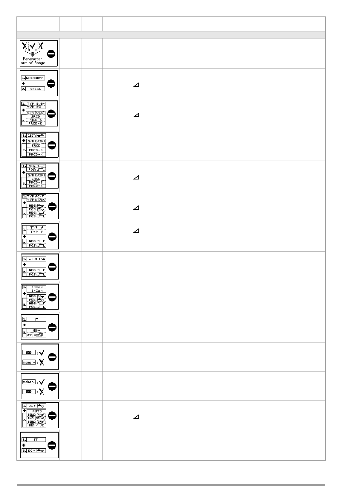
Status
Tes t
plug
Meas.
Adapter
Position of the
Function Switch
Function / Meaning
Entry Plausibility Check – Parameters Combination Checking — LCD Pictographs
Parameter out of range
IΔN / IF 5 x 500 mA is not possible
IΔN / IF Type B, B+ and EV/MI not possible with G/R, SRCD and PRCD
I
ΔN
/ IF DC not possible with G/R, SRCD, PRCD
I
ΔN
180° not possible for G/R, SRCD, PRCD
IΔN / IF Half-wave or DC not possible with type AC, F, B+ and EV/MI
IΔN / IF
DC not possible with type A
EXTRA → RCM
1/2 test current not possible with DC
I
ΔN
I
2 x / 5 x IdN with full-wave only
ΔN
R
E
Not without probe in IT network!
Battery powered measurement not possible,
R
E
R
E
/ IF DC+ with 10 Ω only
I
ΔN
R
E
78 GMC-I Messtechnik GmbH
e.g. with 4-pole adapter connected to the test plug,
or for 2-clamp measurement of measurement of soil resistivity
Mains powered measurement not possible,
e.g. with 2/3-pole adapter connected to the test plug
No DC bias magnetization in the IT network
Page 79

Status
Tes t
plug
Meas.
Adapter
Position of the
Function Switch
Function / Meaning
R
E
R
E
15 mA only possible in the 1 kΩ and 100 Ω range!
15 mA only as loop measurement with or without probe
EXTRA → RCM With RCM: TYPE AC, F , B, B+ and EV/MI not possible
I
/ IF No measurement with half-wave or DC in the IT network
ΔN
The parameters you have selected do not make sense in combination
All
with previously configured parameters. The selected parameter settings
will not be saved.
Remedy: Enter other parameter settings.
R
E
2 pole measurement via earthing contact plug (not possible in IT systems)
EXTRA → ta+IΔ The intelligent ramp is not possible with RCD types RCD-S and G/R.
GMC-I Messtechnik GmbH 79
Page 80

Status
Tes t
plug
Meas.
Adapter
Position of the
Function Switch
Function / Meaning
Messages — LCD Pictographs — Test sequences
The test sequence includes a measurement which cannot be processed
AUTO
AUTO The test sequence has been successfully completed.
AUTO
by the connected test instrument. The respective test step must be
skipped. Example: The test sequence includes a RCM measurement
which has been transferred to PROFITEST MTECH.
There are no test sequences available.
Cause: They may have been deleted by the following operations: Chang-
ing of language, profile, DB mode or by resetting the test instrument to
default values.
Error Messages — LCD Pictographs — PRO-AB Leakage Current Adapter
Measuring range exceeded
EXTRA → I
EXTRA → I
Change into the bigger measuring range (test instrument and leakage
L
current measuring adapter).
Test measurement:
The test has been passed sucessfully.
L
The leakage current measuring adapter is now ready for use.
EXTRA → I
EXTRA → I
Test measurement:
The test has failed.
L
The leakage current measuring adapter is defective.
Please consult our repair service.
Test measurement:
L
Check the fuse in the leakage current measuring adapter.
80 GMC-I Messtechnik GmbH
Page 81

Status
Tes t
plug
Meas.
Adapter
Position of the
Function Switch
Database and Entry Operations — LCD Pictographs
IΔN / IF
Z
/ Z
L-N
EXTRA → t
EXTRA → RCM
All Please enter a designation (alphanumeric).
All
All
L-PE
A+IΔ
Function / Meaning
Saving a measured value with differing electrical circuit parameter
The electrical circuit parameter you have set at the test instrument does
not correspond to the parameter saved in the structure under object data.
Example: The residual operating current defined in the database is 10 mA,
whereas you have performed measurements with 100 mA. If you wish to
perform all future measurements with 100 mA, the value must be modified in the database by acknowledging it with . The measured value
will be documented and the new parameter will be accepted.
If you wish to leave the parameter in the database unchanged, press key
. Measured value and modified parameter will only be documented.
Operation with a Barcode Scanner
Error message appears when the “EDIT” entry field is opened and battery
voltage is less than 8 V. Output voltage is generally switched off during
barcode scanner operation if U is less than 8 V in order to assure that
remaining battery capacity is adequate for entering designations for
devices under test and saving the measurement.
Remedy: Rechargeable batteries must be recharged, or replaced towards
the end of their service life.
Operation with a Barcode Scanner
Current flowing through the RS 232 port is too high.
Remedy:
The connected device is not suitable for this port.
All
All
All
All
All
SETUP
Operation with a Barcode Scanner
Barcode not recognized, incorrect syntax
Data cannot be entered at this location within the structure.
Remedy: Observe profile for preselected PC software (see SETUP menu).
Measured value cannot be saved at this location within the structure.
Remedy: Make sure that you have selected the right profile for you PC
evaluation program in the SETUP menu (see section 4.6).
Memory is full.
Remedy: Save your measurement data to a PC and then clear memory at
test instrument by deleting the database or by importing an empty database.
Delete measurement or database.
This prompt window asks you to confirm deletion.
Data loss after changing language or profile,
or after restoring default settings.
Back up your measurement data to a PC before pressing the respective
key.
This prompt window asks you to confirm deletion.
This error message appears when the database, i. e. the structure created in the ETC software, is too large for the device memory.
All
GMC-I Messtechnik GmbH 81
The database in the device memory is empty after database transfer has
been interrupted.
Remedy: Reduce the database in ETC or send the database without
measured vales (key Send structure) if measured values should already be
available.
Page 82

19 Characteristic Values
Characteristic Values MBASE+ & MTECH+
Func-
tion
Measured
Quantity
U
L-PE
U
N-PE
f
U
U
U
3~
PROBE
U
L-N
U
IΔN
Display Range
0 ... 99.9 V 0.1 V
100 ... 600 V 1 V ±(2% rdg.+1d) ±(1% rdg.+1d)
15.0 ... 99.9 Hz
100 ... 999 Hz
0 ... 99.9 V
100 ... 600 V
0 ... 99.9 V
100 ... 600 V
0 ... 99.9 V
100 ... 600 V
0 ... 70.0 V 0.1 V 0.3 · I
10 Ω ... 999 Ω
1.00 kΩ ... 6.51 k
3 Ω ... 999 Ω
1 kΩ ... 2.17 kΩ
R
E
I
ΔN
IF (IΔN = 6 mA) 1.8 ... 7.8 mA
I
I
(IΔN = 10 mA) 3.0 ... 13.0 mA 3.0 ... 13.0 mA 3.0 ... 13.0 mA
F
F
I
(IΔN = 30 mA) 9.0 ... 39.0 mA 9.0 ... 39.0 mA 9.0 ... 39.0 mA
F
(IΔN = 100 mA) 30 ... 130 mA 1 mA 30 ... 130 mA 30 ... 130 mA
I
F
(IΔN = 300 mA) 90 ... 390 mA 1 mA 90 ... 390 mA 90 ... 390 mA
I
F
I
(IΔN = 500 mA) 150 ... 650 mA 1 mA 150 ... 650 mA 150 ... 650 mA
F
/ UL = 25 V 0 ... 25.0 V
U
IΔ
/ UL = 50 V 0 ... 50.0 V 0 ... 50.0 V
U
IΔ
t
(IΔN · 1) 0 ... 1000 ms 1 ms 6 ... 500 mA 0 ... 1000 ms
A
(IΔN · 2) 0 ... 1000 ms
A
(IΔN · 5) 0 ... 40 ms 1 ms
t
A
Z
()
L-P E
Z
L-N
Z
L-P E
+ DC
I
(Z
K
Z
L-P E
,
L-P E
Z
L-PE
Z
L-N
+ DC)
0.3 Ω ... 99.9 Ω
100 Ω ... 217 Ω
0.2 Ω ... 9.9 Ω
10 Ω ... 130 Ω
1.00 ... 9.99 Ω
1.00 ... 9.99 Ω
10.0 ... 29.9 Ω
1.00 ... 9.99 kA
10.0 ... 50.0 kA
1Ω ... 651 Ω 1Ω
0 ... 999 mΩ
0 ... 999 mΩ
0 ... 9.9 A
10 ... 999 A
Resolution
0.1 Hz
1 Hz
0.1 V
1 V
0.1 V
1 V
0.1 V
1 V
1 Ω
Ω
0.01 kΩ
1 Ω
0.01 kΩ
0.1 Ω
1 Ω
0.1 Ω
1 Ω
0,1 mA
0.1 V wie I
1 mΩ
0.01 Ω
0.1 Ω
0,1 A
1 A
10 A
100 A
0.5 ... 9.99 Ω 0.01 Ω only display range
Z
(15 mA)
L-PE
IK (15 mA)
RE (with probe)
[R
(without probe)
E
values as Z
R
E
RE DC+
U
E
R
R
TRA
E
clip
EX-
Sel
E
RE DC+ 0 ... 999 Ω
Z
ST
10.0 ... 99.9 Ω
100 ... 999 Ω
100 ... 999 mA
0.00 ... 9.99 A
10.0 ... 99.9 A
0 ... 999 mΩ
1.00 ... 9.99 Ω
10.0 ... 99.9 Ω
100 ... 999 Ω
]
L-PE
1 kΩ ... 9.99 kΩ
0 ... 999 mΩ
1.00 ... 9.99 Ω
10.0 ... 29.9 Ω
0 ... 253 V 1 V — calculated value
0 ... 999 Ω
0 ... 30 MΩ 1 kΩ 2.3 mA at 230 V
0.1 Ω
1 Ω
1 mA
0.01 A
0.1 A
1 mΩ
0,01 Ω
0,1 Ω
1 Ω
0.01 kΩ
1 mΩ
0.01 Ω
0.1 Ω
1 mΩ ...
1 Ω
1 mΩ ...
1 Ω
Input
Impedance/
Tes t Curr ent
5 MΩ
ΔN
I
= 10 mA · 1,05
Δ
N
I
= 30 mA · 1,05
Δ
N
I
=100 mA · 1,05
Δ
N
I
=300 mA · 1,05
Δ
N
I
=500 mA · 1,05
Δ
N
1.8 ... 7.8 mA 1.8 ... 7.8 mA
Δ
2 · 6 ... 2 · 500 mA
5 · 6 ... 5 · 300 mA
1.3 ... 3.7 A AC
0.5/1.25 A DC
15 mA AC
1.3 ... 3.7 A AC
1.3 ... 3.7 A AC
1.3 ... 3.7 A AC
400 mA AC
40 mA AC
4 mA AC
1.3 ... 3.7 A AC
0.5/1.25 A DC
1.3 ... 3.7 A AC
0.5/1.25 A DC
Measuring Range Nominal Values
0.3 ... 600 V
DC 15,4 ... 420 Hz ±(0.2% rdg.+1d) ±(0.1% rdg.+1d)
1)
UN = 120/230/
400/500 V
0.3 ... 600 V
1.0 ... 600 V
1.0 ... 600 V
= 162/3/50/
f
N
60/200/400 Hz
1
5 ... 70 V
U
=
calculated value
from
U
IΔN / IΔN
N
120 V
230 V
400 V
Measuring
Uncertainty
±(2% rdg.+5d) ±(1% rdg.+5d)
±(3% rdg.+5d)
±(3% rdg.+1d)
±(2% rdg.+5d)
±(2% rdg.+1d)
±(3% rdg.+5d)
±(3% rdg.+1d)
+10% rdg.+1d
2
Intrinsic
Uncertainty
±(2% rdg.+5d)
±(2% rdg.+1d)
±(1% rdg.+5d)
±(1% rdg.+1d)
±(2% rdg.+5d)
±(2% rdg.+1d)
+1% rdg.–1d ...
+9% rdg.+1d
fN = 50/60 Hz
U
= 25/50 V
L
I
=
ΔN
0 ... 25.0 V
0 ... 1000 ms
6 mA
10 mA
30 mA
100 mA
300 mA
500 mA
±(5% rdg.+1d) ±(3.5% rdg.+2d)
2
+10% rdg.+1d
±4 ms ±3 mst
+1% rdg.–1d ...
+9% rdg.+1 d
0 ... 40 ms
0.15 ... 0.49 Ω
0.50 ... 0.99 Ω
1.00 ... 9.99 Ω
0.25 ... 0.99 Ω
1.00 ... 9.99 Ω
120 (108 ... 132) V
230 (196 ... 253) V
400 (340 ... 440) V
500 (450 ... 550) V
10 ... 100 Ω
100 ... 1000 Ω
calcul. value depends
on UN and Z
/10...1000Ω
I
K=UN
0.15 Ω ... 0.49 Ω
0.50 Ω ... 0.99 Ω
1.0 Ω ...9.99 Ω
10 Ω ...99.9 Ω
100 Ω ...999 Ω
1 kΩ ...9.99 kΩ
0.25 ... 0.99 Ω
1.00 ... 9.99 Ω
0.25 ... 300 Ω
10 kΩ ... 199 kΩ
200 kΩ ... 30 MΩ
L-PE
U
N
400/500 V
fN=162/
U
N
f
N
U
N
fN =
:
U
N
U
fN = 50/60 Hz
U
N
f
N
5)
U
N
f
N
= 120/230 V
1
8
/50/60Hz
3
= 120/230 V
= 50/60 Hz
= 120/230 V
8
162/
/
50/
3
Hz
60
= 120/230 V
= 400 V
N
= 120/230 V
= 50/60 Hz
see RE±
= 120/230 V
= 50/60 Hz
U0 = U
L-N
±(10% rdg.+ 30d)
±(10% rdg.+ 30d)
±(5% rdg.+ 3d)
±(18% rdg.+30d)
±(10% rdg.+3d)
±(5% rdg.+30d)
±(4% rdg.+30d)
±(3% rdg.+3d)
±(6% rdg.+50d)
±(4% rdg.+3d)
calculated value from Z
±
(10% rdg.+10D)
±
(8% rdg.+2D)
calculated value from Z
I
K
±(10% rdg.+30d)
±(10% rdg.+30d)
±(5% rdg.+3d)
1
±(10% rdg.+3d)
±(10% rdg.+3d)
±(10% rdg.+3d)
±
(18% rdg.+ 30d)
±(10% rdg. + 3d)
= UN/Z
±
(2% rdg.+2D)
±
(1% rdg.+1D)
L-PE
(15 mA)
L-PE
±(5% rdg.+30d)
±(4% rdg.+30d)
±(3% rdg.+3d)
±(3% rdg.+3d)
±(3% rdg.+3d)
±(3% rdg.+3d)
±(6% rdg.+50D)
±(4% rdg.+3D)
(20% rdg.+ 20 d)±(15% rgd.+ 20 d)
±
(22% rdg.+20 d)±(15% rdg.+ 20 d)
±(20% rdg.+2d)
±(10% rdg.+2d)
±(10% rdg.+3d)
±(5% rdg.+3d)
L-PE
(15 mA):
Connections
Plug
2-Pole
3-Pole
Insert
1
Adapter
Adapter
Probe
●●●
●
●
●●
●
●●
●
●
Z
L-PE
optio
nal
●● ●
●●●●
Clamps
WZ12C Z3512A
●
MFLEX
P300
●
82 GMC-I Messtechnik GmbH
Page 83

Func-
R
R
tion
INS
Measured
Quantity
R
. R
INS
E INS
Display Range
1 ... 999 kΩ
1.00 ... 9.99 MΩ
10.0 ... 49.9 MΩ
1 ... 999 kΩ
1.00 ... 9.99 MΩ
10.0 ... 99.9 MΩ
1 ... 999 kΩ
1.00 ... 9.99 MΩ
10.0 ... 99.9 MΩ
100 ... 200 MΩ
1 ... 999 kΩ
1.00 ... 9.99 MΩ
10.0 ... 99.9 MΩ
100 ... 500 MΩ
U
R
LO
LO
10 ... 999 V–
1.00 ... 1.19 kV
0.01 Ω ... 9.99 Ω
10.0 Ω ... 99.9 Ω
Reso-
Test Current Measuring Range Nominal Values
lution
1 kΩ
10 kΩ
100 kΩ
1 kΩ
10 kΩ
100 kΩ
1 kΩ
I
= 1.5 mA 50 kΩ ... 500 MΩ
K
10 kΩ
100 kΩ
1 MΩ
1 kΩ
10 kΩ
100 kΩ
1 MΩ
1 V
10 V
10 mΩ
100 mΩ
Im ≥ 200 mA
< 200 mA
I
m
Tra nsf orma -
tion
ratio
10 ... 1.19 kV ±(3% rdg.+1d)
0.1 Ω ... 5.99 Ω
6.0 Ω ... 100 Ω
3
0.0 ... 99.9 mA 0.1 mA
100 ... 999 mA 1 mA
1 V/A 5 ... 15 A
10.0 ... 15.0 A 0.1 A
1.00 ... 9.99 A 0.01 A
10.0 ... 99.9 A 0.1 A
1 mV/A 5 ... 150 A
100 ... 150 A 1 A
0.0 ... 99.9 mA 0.1 mA
100 ... 999 mA 1 mA ±(7% rdg.+1 d) ±(5% rdg.+1 d)
1 V/A 5 ... 1000 mA
0.00 ... 9.99 A 0.01 A 100 mV/A 0.05 ... 10 A ±(3.4% rdg.+2 d) ±(3% rdg.+2 d)
SEN-
SOR
6
7
I
L/Amp
0.00 ... 9.99 A 0.01 A
10.0 ... 99.9 A 0.1 A ±(3.1% rdg.+1 d) ±(3% rdg.+1 d)
0.00 ... 9.99 A 0.01 A
10.0 ... 99.9 A 0.1 A ±(3.1% rdg.+2 d) ±(3% rdg.+2 d)
100 ... 999 A 1 A ±(3.1% rdg.+1 d) ±(3% rdg.+1 d)
0.0 ... 99.9 mA 0.1 mA
100 ... 999 mA 1 mA
0.00 ... 9.99 A
0.01 A
0.01 A
0.00 ... 9.99 A 0.01 A
10.0 ... 99.9 A 0.1 A
0.00 ... 9.99 A 0.01 A
10.0 ... 99.9 A 0.1 A ±(5% rdg.+2 d)
10 mV/A 0.5 ... 100 A
1 mV/A 5 ... 1000 A
1 V/A 30 ... 1000 mA
100 mV/A 0.3 ... 10 A
10 mV/A 3 ... 100 A
10 mV/A 0.5 ... 100 A
0.00 ... 9.99 A 0.01 A
10.0 ... 99.9 A 0.1 A ±(5% rdg.+7 d)
1 mV/A 5 ... 1000 A
100 ... 999 A 1 A ±(5% rdg.+2 d)
1
U > 253 V, with 2 or 3-pole adapter only
2
1
·
/ 2
·
IN > 300 mA and 5
IN 5
·
300 mA only with UN = 230 V
3
The transformation ratio selected at the clamp (1 ... 1000 mV/A) must be set in the
“Type” menu with the rotary switch in the “SENSOR” position.
4
at R
Eselektiv/REgesamt
5
the indicated measuring and int rinsic uncertainties already incl ude the uncertainties
of the respective current clamp.
6
Measuring range of the signal input at the test instrument UE: 0 ... 1.0 V
Vpeak) AC/DC
7
Input impedance of signal input at the test instrument: 800 kΩ
8
for fN < 45 Hz => UN < 253 V
·
IN > 500 mA and If > 300 mA only up to UN≤ 230 V !
< 100
(0 ... 1.4
eff
Measuring
Uncertainty
= 50 V
U
N
= 1 mA
I
N
= 100 V
U
N
= 1 mA
I
N
= 250 V
U
N
= 1 mA
I
N
U
= 500 V/
N
1000 V
I
= 1 mA
N
U
= 4.5 V ±(4% rdg.+2d) ±(2% rdg.+2d)
0
kΩ range
±(5% rdg.+10d)
MΩ range
±(5% rdg.+1d)
55
Uncertainty
±(3% rdg.+10d)
±(3% rdg.+1d)
±
(1.5% rdg.+1d)
±(13% rdg.+5d) ±(5% rdg.+4d)
±(13% rdg.+1d) ±(5% rdg.+1d)1.00 ... 9.99 A 0.01 A
f
= 50/60 Hz
N
±(11% rdg.+4d) ±(4% rdg.+3d)
±(11% rdg.+1d) ±(4% rdg.+1d)
±(7% rdg.+2 d) ±(5% rdg.+2 d)
f
=
N
16.7/50/60/
200/400 Hz
±(3.1% rdg.+2 d) ±(3% rdg.+2 d)
±(3.1% rdg.+1 d) ±(3% rdg.+1 d)
±(27% rdg.+100 d) ±(3% rdg.+100 d)
= 50/60 Hz
f
N
±(27% rdg.+11 d)
±(27% rdg.+12 d)
±(27% rdg.+11 d)
±(3% rdg.+11 d)
±(3% rdg.+12 d)
±(3% rdg.+11 d)
±(27% rdg.+100 d) ±(3% rdg.+100 d)
f
=
N
DC/16.7/50/60/
200 Hz
±(27% rdg.+11 d)
±
(5% rdg.+12 d)±(3% rdg.+12 d)
±
(5% rdg.+50 d) ±(3% rdg.+50 d)
±(3% rdg.+11 d)
±(3% rdg.+2 d)
±(3% rdg.+7 d)
±(3% rdg.+2 d)
Intrinsic
kΩ range
MΩ range
Plug
2-Pole
1
Insert
Adapter
●●
●
Connections
3-Pole
Adapter
Clamps
WZ12C Z3512A
I 15A
II 150A
1 A
10 A
100 A
1000A
MFLEX
P300
0.03
3
0.3
30
3
300
CP1100
100A
~
1000A
~
Key: D = digits, rdg. = measured value (reading)
GMC-I Messtechnik GmbH 83
Page 84

Characteristic Values MPRO, MXTRA & SECULIFE IP
Func-
tion
U
Measured
Quantity
U
L-PE
U
N-PE
f
U
3~
U
Probe
U
L-N
U
IΔN
Display Range
0 ... 99.9 V 0.1 V
100 ... 600 V 1 V ±(2% rdg. + 1 d) ±(1% rdg. + 1 d)
15.0 ... 99.9 Hz
100 ... 999 Hz
0 ... 99.9 V
100 ... 600 V
0 ... 99.9 V
100 ... 600 V
0 ... 99.9 V
100 ... 600 V
0 ... 70.0 V 0.1 V 0.3 · I
10 Ω ... 999 Ω
1.00 kΩ ... 6.51 kΩ
3 Ω ... 999 Ω
1 kΩ ... 2.17 kΩ
+ DC)
0.3 Ω ... 99.9 Ω
100 Ω ... 217 Ω
0.2 Ω ... 9.9 Ω
10 Ω ... 130 Ω
1.00 ... 9.99 Ω
1.00 ... 9.99 Ω
10.0 ... 29.9 Ω
1.00 ... 9.99 kA
10.0 ... 50.0 kA
0.5 ... 99.9 Ω
100 ... 999 Ω
1Ω ... 651 Ω 1Ω
0 ... 999 mΩ
0 ... 999 mΩ
0 ... 9.9 A
10 ... 999 A
R
E
I
ΔN
IF (IΔN = 6 mA) 1.8 ... 7.8 mA
I
(IΔN = 10 mA) 3.0 ... 13.0 mA 3.0 ... 13.0 mA 3.0 ... 13.0 mA
I
F
F
(IΔN = 30 mA) 9.0 ... 39.0 mA 9.0 ... 39.0 mA 9.0 ... 39.0 mA
I
F
(IΔN = 100 mA) 30 ... 130 mA 1 mA 30 ... 130 mA 30 ... 130 mA
I
F
(IΔN = 300 mA) 90 ... 390 mA 1 mA 90 ... 390 mA 90 ... 390 mA
I
F
(IΔN = 500 mA) 150 ... 650 mA 1 mA 150 ... 650 mA 150 ... 650 mA
I
F
/ UL = 25 V 0 ... 25.0 V
U
IΔ
/ UL = 50 V 0 ... 50.0 V 0 ... 50.0 V
U
IΔ
(IΔN · 1) 0 ... 1000 ms 1 ms 6 ... 500 mA 0 ... 1000 ms
t
A
(IΔN · 5) 0 ... 40 ms 1 ms
t
A
Z
()
L-P E
Z
L-N
Z
L-P E
+ DC
Z
I
(Z
Z
K
L-P E
L-P E
Z
L-P E
,
(15 mA)
Z
L-P E
L-N
0.10 ... 9.99 A
R
E
probe) + DC
RE
Sel
Clamp
EXTRA
EXTRA
IK (15 mA)
R
(without
E.sl
probe)
(with probe)
R
E
R
E (15 mA)
(without/with probe)
R
(without
E.sl
R
(with probe)
E.sl
+ DC
U
E
R
E.sel
(only with probe)
R
E.sel
+ DC
(only with probe)
Z
ST
IMD test
10.0 ... 99.9 A
100 ... 999 A
0 ... 999 mΩ
1.00 ... 9.99 Ω
10.0 ... 99.9 Ω
100 ... 999 Ω
1 kΩ ... 9.99 kΩ
0.5 ... 99.9 Ω
100 ... 999 Ω
0 ... 999 mΩ
1.00 ... 9.99 Ω
10.0 ... 29.9 Ω
0 ... 253 V 1 V 3.7 ... 4.7 A AC
0 ... 999 mΩ
1.00 ... 9.99 Ω
10.0 ... 99.9 Ω
100 ... 999 Ω
0 ... 999 mΩ
1.00 ... 9.99 Ω
10.0 ... 99.9 Ω
100 ... 999 Ω
0 to 30 MΩ 1 kΩ 2.3 mA at 230 V
20 ... 648 kΩ
2.51 MΩ
Resolution
0.1 Hz
0.01 kΩ
0.01 kΩ
0,1 mA
0.01 Ω
0.01 A
14)
0.01 Ω
0.01 kΩ
0.01 Ω
0.01 Ω
0.01 Ω
0.01 MΩ
1 Hz
0.1 V
1 V
0.1 V
1 V
0.1 V
1 V
1 Ω
1 Ω
0.1 Ω
1 Ω
0.1 Ω
1 Ω
0.1 V Same as I
1 mΩ
0.1 Ω
0,1 A
1 A
10 A
100 A
0.1 Ω
1 Ω
0.1 A
1 A
1 mΩ
0.1 Ω
1 Ω
0.1 Ω
1 Ω
1 mΩ
0.1 Ω
1 mΩ
0.1 Ω
1
1 mΩ
0.1 Ω
1
1 kΩ
Input
Impedance /
Test Current
5 MΩ
ΔN
I
= 10 mA · 1.05
Δ
N
I
= 30 mA · 1.05
Δ
N
I
=100 mA · 1.05
Δ
N
I
=300 mA · 1.05
Δ
N
I
=500 mA · 1.05
Δ
N
1.8 ... 7.8 mA 1.8 ... 7.8 mA
2 · 6 ... 2 · 500 mA
5 · 6 ... 5 · 300 mA
3.7 ... 4.7 A AC
3.7 ... 4.7 A AC
0.5/1.25 A DC
15 mA AC
3.7 ... 4.7 A AC
3.7 ... 4.7 A AC
400 mA AC
40 mA AC
4 mA AC
15 mA AC
3.7 ... 4.7 A AC
0.5/1.25 A DC
2.1 A AC
2.1 A AC
400 mA AC
Ω
40 mA AC
3.7 ... 4.7 A AC
0.5/1.25 A DC
Ω
IT line voltage
U.it = 90 ... 550 V
Measuring
Range
0.3 ... 600 V
DC 15.4 ... 420 Hz
0.3 ... 600 V
1.0 ... 600 V
1.0 ... 600 V
5 ... 70 V
calculated value
R
= U
E
0 ... 25.0 V
Δ
0 ... 1000 ms
0 ... 40 ms
0.10 ... 0.49 Ω
0.50 ... 0.99 Ω
1.00 ... 9.99 Ω
0.25 ... 0.99 Ω
1.00 ... 9.99 Ω
120 (108 ... 132) V
230 (196 ... 253) V
400 (340 ... 440) V
500 (450 ... 550) V
10 ... 100 Ω
100 ... 1000 Ω
100 mA ... 12 A
(U
N
200 mA ... 25 A
(U
N
0.10 Ω ... 0.49 Ω
0.50 Ω ... 0.99 Ω
1.0 Ω ...9.99 Ω
10 Ω ...99.9 Ω
100 Ω ...999 Ω
1 kΩ ... 9.99 kΩ
10 Ω ...99.9 Ω
100 Ω ...999 Ω
0.25 ... 0.99 Ω
1.00 ... 9.99 Ω
RE = 0.10 ... 9.99
0.25 ... 300 Ω
0.25 ... 300 Ω
R
E.tot
10 kΩ ... 199 kΩ
200 kΩ ... 30 MΩ
20 kΩ ... 199 kΩ
200 kΩ ... 648 kΩ
2.51 MΩ
Off
IΔN / IΔN
= 120 V)
= 230 V)
< 10 Ω
Nominal
1
= 162/3/50/
f
N
60/200/400 Hz
1
fN = 50/60 Hz
U
L
UN ≤ 230 V
UN ≤ 230 V
= 120/230 V
U
N
400/500 V
fN =162/
= 120/230 V
U
N
= 50/60 Hz
f
N
U
= 120/230 V
N
= 162/
f
N
UN same as U
fN = 50/60 Hz
UN = 120/230 V
= 50/60 Hz
f
N
= 120/230 V
U
N
= 50/60 Hz
f
N
UN = 120/230 V
Ω
= 50/60 Hz
f
N
UN = 120/230 V
4
= 50/60 Hz
f
N
UN = 120/230 V
4
= 50/60 Hz
f
N
IT system nomi-
nal voltages
120/230/400/
= 50/60 Hz
f
N
Values
UN =
120 V
230 V
400 V
500 V
UN =
120 V
230 V
400 V
= 25/50 V
I
=
ΔN
6 mA
10 mA
30 mA
100 mA
300 mA
500 mA
8
/50/60 Hz
3
3
60 Hz
function
U0 = U
L-N
UN.it =
500 V
Measuring
Uncertainty
±(2% rdg.+5d) ±(1% rdg.+5d)
±
(0.2% rdg. + 1 d)
±(3% rdg.+5d)
±(3% rdg. + 1 d)
±(2% rdg.+5d)
±(2% rdg. + 1 d)
±(3% rdg.+5d)
±(3% rdg. + 1 d)
+10% rdg. + 1 d
±(5% rdg. + 1 d)
2
+10% rdg. + 1 d
±4 ms ±3 mstA (IΔN · 2) 0 ... 1000 ms 1 ms
±
(10% rdg.+20d)
1
±
(10% rdg.+20d)
±(5% rdg.+3d)
±
(18% rdg.+30d)
±(10% rdg.+3d)
Value calculated from Z
±
(10% rdg.+10d)
±
(8% rdg. + 2 d)
8
/
50/
1
Value calculated from
I
= UN/Z
K
±
(10% rdg.+20d)
±
(10% rdg.+20d)
±(5% rdg.+3d)
±(10% rdg.+3d)
±(10% rdg.+3d)
±(10% rdg.+3d)
±
(10% rdg.+10d)
±
(8% rdg. + 2 d)
±
(18% rdg.+30d)
±(10% rdg.+3d)
Calculated U
±
(20% rdg.+20 d)±(15% rdg.+20 d)
±
(22% rdg.+20 d)±(15% rdg.+20 d)
±(20% rdg. + 2 d)
±(10% rdg. + 2 d)
±7%
±12%
±3%
Intrinsic
Uncertainty
±(0.1% rdg. + 1 d)
±(2% rdg.+5d)
±(2% rdg. + 1 d)
±(1% rdg.+5d)
±(1% rdg.+1d)
±(2% rdg.+5d)
±(2% rdg. + 1 d)
+1% rdg. –1d
+9% rdg. + 1 d
±(3.5% rdg. + 2
d)
+1% rdg. –1d
+9% rdg.+ 1d
±(5% rdg.+
±(4% rdg.+
±(3% rdg.+3d)
±(6% rdg.+50d)
±(4% rdg.+3d)
L-P E
±
(2% rdg. + 2 d)
±
(1% rdg. + 1 d)
(15 mA)
L-P E
±(5% rdg.+
±(4% rdg.+
±(3% rdg.+3d)
±(3% rdg.+3d)
±(3% rdg.+3d)
±(3% rdg.+3d)
±(2% rdg. + 2 d)
±(1% rdg. + 1 d)
±(6% rdg.+50d)
±(4% rdg.+3d)
= UN · RE/R
E
±(10% rdg.+3 d)
±(5% rdg.+3 d)
±5%
±10%
±2%
Plug
2-Pole
1
Insert
Adapter
●●●
●●
●●
20d
)
20d
)
●
●
Z
L-P E
20d
)
20d
)
●● ●
E.sl
●●●●
●●
Connections
3-Pole
Adapter
●
Option
Probe
●
●
Clamp
WZ12C Z3512A
●
MFLEX
P300
●
84 GMC-I Messtechnik GmbH
Page 85

Func-
tion
R
R
INS
LO
Measured
Quantity
R
, R
E ISO
INS
U
R
LO
Display Range
1 ... 999 kΩ
1.00 ... 9.99 MΩ
10.0 ... 49.9 MΩ
1 ... 999 kΩ
1.00 ... 9.99 MΩ
10.0 ... 99.9 MΩ
1 ... 999 kΩ
1.00 ... 9.99 MΩ
10.0 ... 99.9 MΩ
100 ... 200 MΩ
1 ... 999 kΩ
1.00 ... 9.99 MΩ
10.0 ... 99.9 MΩ
100 ... 500 MΩ
10 ... 999 V–
1.00 ... 1.19 kV
0.01 Ω ... 9.99 Ω
10.0 Ω ... 199.9 Ω
Reso-
lution
1 kΩ
10 kΩ
100 kΩ
1 kΩ
10 kΩ
100 kΩ
1 kΩ
10 kΩ
100 kΩ
1 MΩ
1 kΩ
10 kΩ
100 kΩ
1 MΩ
1 V
10 V
10 mΩ
100 mΩ
Tes t Current
= 1.5 mA 50 kΩ ... 500 MΩ
I
K
Measuring
Range
10 ... 1.19 kV ±(3% rdg. + 1 d)
ratio
0.1 Ω ... 5.99 Ω
6.0 Ω ... 100 Ω
3
Im ≥ 200 mA
< 200 mA
I
m
Tra ns fo rma -
tion
0.0 ... 99.9 mA 0.1 mA
100 ... 999 mA 1 mA
1 V/A 5 ... 15 A
10.0 ... 15.0 A 0.1 A
1.00 ... 9.99 A 0.01 A
10.0 ... 99.9 A 0.1 A
100 ... 150 A 1 A
0.0 ... 99.9 mA 0.1 mA
100 ... 999 mA 1 mA ±(7% rdg.+1 d) ±(5% rdg.+1 d)
1 mV/A 5 ... 150 A
1 V/A 5 ... 1000 mA
0.00 ... 9.99 A 0.01 A 100 mV/A 0.05 ... 10 A ±(3.4% rdg.+2 d) ±(3% rdg.+2 d)
0.00 ... 9.99 A 0.01 A
SEN-
SOR
6
7
I
L/Amp
10.0 ... 99.9 A 0.1 A ±(3.1% rdg.+1 d) ±(3% rdg.+1 d)
0.00 ... 9.99 A 0.01 A
10.0 ... 99.9 A 0.1 A ±(3.1% rdg.+2 d) ±(3% rdg.+2 d)
100 ... 999 A 1 A ±(3.1% rdg.+1 d) ±(3% rdg.+1 d)
0.0 ... 99.9 mA 0.1 mA
100 ... 999 mA 1 mA
0.00 ... 9.99 A
0.01 A
0.01 A
0.00 ... 9.99 A 0.01 A
10.0 ... 99.9 A 0.1 A
0.00 ... 9.99 A 0.01 A
10.0 ... 99.9 A 0.1 A ±(5% rdg.+2 d)
0.00 ... 9.99 A 0.01 A
10.0 ... 99.9 A 0.1 A ±(5% rdg.+7 d)
1
U > 230 V with 2 or 3-pole adapter only
2
1
·
/ 2
·
IN > 300 mA and 5
3
The transformation ratio selected at the clamp (1 ... 1000 mV/A) must be set in the
“Type” menu with the rotary switch in the “SENSOR” position.
4
Where R
Eselective/REtotal
100 ... 999 A 1 A ±(5% rdg.+2 d)
·
IN > 500 mA and If > 300 mA only up to UN≤ 230 V !
< 100
10 mV/A 0.5 ... 100 A
1 mV/A 5 ... 1000 A
1 V/A 30 ... 1000 mA
100 mV/A 0.3 ... 10 A
10 mV/A 3 ... 100 A
10 mV/A 0.5 ... 100 A
1 mV/A 5 ... 1000 A
Nominal
Values
U
= 50 V
N
I
= 1 mA
N
= 100 V
U
N
= 1 mA
I
N
= 250 V
U
N
= 1 mA
I
N
U
= 500 V
N
= 1000 V
U
N
= 1 mA
I
N
U
= 4.5 V ±(4% rdg. + 2 d) ±(2% rdg. + 2 d)
0
Measuring
Uncertainty
kΩ range
±(5% rdg.+10D)
MΩ range
±(5% rdg. + 1 d)
55
Intrinsic
Uncertainty
kΩ
±(3% rdg.+10d)
MΩ
±(3% rdg. + 1 d)
±
(1.5% rdg. + 1 d)
range
range
Plug
1
Insert
●●
2-Pole
Adapter
●
Connections
3-Pole
Adapter
WZ12C Z3512A
±(13% rdg.+5d) ±(5% rdg.+4d)
I 15A
II 150A
f
= 50/60 Hz
N
±(13% rdg.+1d) ±(5% rdg.+1d)1.00 ... 9.99 A 0.01 A
±(11% rdg.+4d) ±(4% rdg.+3d)
±(11% rdg.+1d) ±(4% rdg.+1d)
±(7% rdg.+2 d) ±(5% rdg.+2 d)
=
f
N
16.7/50/60/200/
400 Hz
±(3.1% rdg.+2 d) ±(3% rdg.+2 d)
±(3.1% rdg.+1 d) ±(3% rdg.+1 d)
±(27% rdg.+100 d) ±(3% rdg.+100 d)
= 50/60 Hz
f
N
±(27% rdg.+11 d)
±(27% rdg.+12 d)
±(27% rdg.+11 d)
±(3% rdg.+11 d)
±(3% rdg.+12 d)
±(3% rdg.+11 d)
±(27% rdg.+100 d) ±(3% rdg.+100 d)
±(27% rdg.+11 d)
±
f
=
N
DC/16.7/50/60/
200 Hz
5
6
7
8
(5% rdg.+12 d)±(3% rdg.+12 d)
±
(5% rdg.+50 d) ±(3% rdg.+50 d)
the indicated measuring and intrinsic uncertainties already include the uncertainties
of the respective current clamp.
Measuring range of the signal input at the test instrument UE: 0 ... 1.0 V
Input impedance of signal input at the test instrument: 800 kΩ
for fN < 45 Hz => UN < 253 V
±(3% rdg.+11 d)
±(3% rdg.+2 d)
±(3% rdg.+7 d)
±(3% rdg.+2 d)
(0 ... 1.4 Vpeak) AC/DC
eff
Clamp
1 A
10 A
100 A
1000A
MFLEX
P300
0.03
3
0.3
30
3
300
CP1100
100A
~
1000A
~
Special Function MPRO, MXTRA
Func-
Measured
tion
Quantity
RE, 3-pole
RE, 4-pole ±(10% rdg.+10d) ±(3% rdg.+5d)
RE, 4-pole
Selective
With clamp meter
RE
BAT
Soil resistivity
(p)
Probe distance
d (p)
RE, 2 clamps
5
Signal frequency without interference signal
6
PRO-RE (Z501S) adapter cable for test plug, for connecting earth probes (E-Set 3/4)
7
PRO-RE/2 (Z502T) adapter cable for test plug, for connecting the generator clamp
(E-CLIP2)
8
Generator clamp: E-CLIP2 (Z591B)
9
Clamp meter: Z3512A (Z225A)
10
Where RE.sel/RE < 10 or clamp current > 500 µA
11
Where RE.H/RE ≤ 100 and RE.E/RE ≤ 100
Display Range
0.00 ... 9.99 Ω
10.0 ... 99.9 Ω
100 ... 999 Ω
1.00 ... 9.99 kΩ
10.0 ... 50.0 kΩ
0.00 ... 9.99 Ω
10.0 ... 99.9 Ω
100 ... 999 Ω
1.00 ... 9.99 kΩ
10.0 ... 19.9 kΩ
10.0 ... 49.9 kΩ
0.0 ... 9.9 Ωm
100 ... 999 Ωm
1.00 ... 9.99 kΩm
0.1 ... 999 m
0.00 ... 9.99 Ω
10.0 ... 99.9 Ω
100 ... 999 Ω
1.00 ... 1.99 kΩ
15
16
Reso-
lution
0.01 Ω
0.1 Ω
1 Ω
0.01 kΩ
0.1 kΩ
0.01 Ω
0.1 Ω
1 Ω
0.01 kΩ
0.1 kΩ
0.1 kΩ
0.1 Ωm
1 Ωm
0.01 kΩm
0.01 Ω
0.1 Ω
1 Ω
0.01 kΩ
Test Current/
Signal
Frequen
cy
16 mA/128 Hz
1.6 mA/128 Hz
0.16 mA/128 Hz
0.16 mA/128 Hz
0.16 mA/128 Hz
16 mA/128 Hz
16 mA/128 Hz
1.6 mA/128 Hz
0.16 mA/128 Hz
0.16 mA/128 Hz
0.16mA/128 Hz
16 mA/128 Hz
1.6 mA/128 Hz
0.16 mA/128 Hz
0.16 mA/128 Hz
0.16mA/128 Hz
30 V / 128 Hz
Measuring Range
5
1.00 Ω ... 19.9 Ω
5.0 Ω ... 199 Ω
50 Ω ... 1.99 kΩ
0.50kΩ ... 19.9kΩ
0.50kΩ ... 49.9kΩ
1.00 Ω ... 9.99 Ω
10.0 Ω ... 200 Ω
100 Ωm ... 9.99 kΩm
500 Ωm ... 9.99 kΩm
5.00 kΩm ... 9.99 kΩm
5.00 kΩm ... 9.99 kΩm
5.00 kΩm ... 9.99 kΩm
0.10 ... 9.99 Ω
10.0 ... 99.9 Ω
Measuring
Uncertainty
±(10% v.M.+10D)
+ 1 Ω
±(15% rdg.+10d)
±(20% rdg.+10d)
10
12
12
±(20% rdg.+10d)11±
13
13
13
±(10% rdg.+5d)
±(20% rdg.+5d)
12
Where d = 20 m
13
Where d = 2 m
14
Where Z
15
Only where RANGE = 20 kΩ
16
Only where RANGE = 50 kΩ or AUTO
< 0.5 Ω, Ik > UN/0.5 Ω is indicated
L-PE
Intrinsic
Uncertainty
±(3% v.M.+5D)
+ 0,5 Ω
±
(10% rdg.+10d)
±
(15% rdg.+10d)
(12% rdg.+10d)
11
±(5% rdg.+5d)
±(12% rdg.+5d)
Adapter for Test Plug
PRO-RE PRO-RE/2 Z3512A Z591B
6
69
6
Connections
798
Key: D = digits, rdg. = measured value (reading)
Current Clamps
GMC-I Messtechnik GmbH 85
Page 86

Characteristic Values PROFITEST MASTER & SECULIFE IP
BAT
Overload Capacity
Reference Conditions
Line voltage 230 V ± 0.1%
Line frequency 50 Hz ± 0.1%
Meas. quantity frequency 45 Hz … 65 Hz
Measured qty. waveform Sine (deviation between effective
and rectified value ≤ 0.1%)
Line impedance angle cos ϕ =1
Probe resistance ≤ 10 Ω
Supply power 12 V ± 0.5 V
Ambient temperature + 23 °C ± 2 K
Relative humidity 40% … 60%
Finger contact For testing potential difference
to ground potential
Standing surface insulation
Purely ohmic
Nominal Ranges of Use
Voltage U
Frequency f
Overall voltage range U
N
N
Y
Overall frequency range 15.4 ... 420 Hz
Waveform Sine
Temperature range 0 °C ... + 40 °C
Supply voltage 8 ... 12 V
Line impedance angle Corresponds to cos ϕ = 1 ... 0.95
Probe resistance < 50 kΩ
120 V (108 ... 132 V)
230 V (196 ... 253 V)
400 V (340 ... 440 V)
16 2/3Hz (15.4 ... 18 Hz)
50 Hz (49.5 ... 50.5 Hz)
60 Hz (59.4 ... 60.6 Hz)
200 Hz (190 ... 210 Hz)
400 Hz (380 ... 420 Hz)
65 ... 550 V
Power Supply
Rechargeable batteries 8 each AA 1.5 V,
we recommend eneloop type AA HR6,
2000 mAh (article no. Z502H)
Number of measurements (standard setup with illumination)
– For R
INS
– For R
LO
Battery test Symbolic display of battery voltage
1 measurement – 25 s pause:
approx. 1100 measurements
Automatic polarity reversal / 1 Ω
(1 measuring cycle) – 25 s pause:
approx. 1000 measurements
R
INS
U
, U
L-P E
RCD, R
Z
, Z
L-P E
E
L-N
L-N
, R
F
1200 V continuous
600 V continuous
440 V continuous
550 V (Limits the number of measure-
ments and pause duration. If overload
occurs, the instrument is switched off
by means of a thermostatic switch.)
R
LO
Fine-wire fuse protection
Electronic protection prevents switching
on if interference voltage is present.
FF 3.15 A 10 s,
Fuses blow at > 5 A −
Electrical Safety
Protection class II per IEC 61 010-1/EN 61010-1/
VDE 0411-1
Nominal voltage 230/400 V (300/500 V)
Test voltage 3.7 kV 50 Hz
Measuring category CAT III 500 V or CAT IV 300 V
Pollution degree 2
Fusing, L and N terminals
1 cartridge fuse-link ea.
FF 3.15/500G 6.3 x 32 mm
Electromagnetic Compatibility (EMC)
Product Standard EN 61326-1:2006
Interference
emission
EN 55022 A
Interference
immunity
EN 61000-4-2 Contact/atmos. –
EN 61000-4-3 10 V/m
EN 61000-4-4 Mains conn. – 2 kV
EN 61000-4-5 Mains conn. – 1 kV
EN 61000-4-6 Mains conn. – 3 V
EN 61000-4-11 0.5 period / 100 %
Test Va l u e F e a t u r e
4 kV/8 kV
Class
Ambient Conditions
Accuracy 0 to + 40 °C
Operation –5 ... + 50 °C
Storage –20 ... + 60 °C (without batteries)
Relative humidity Max. 75 %, no condensation allowed
Elevation Max. 2000 m
Battery saver circuit Display illumination can be switched off.
Mechanical Design
The test instrument is switched off
automatically after the last key operation. The user can select the desired
on-time.
Safety shutdown If supply voltage is too low, the instru-
ment is switched off, or cannot be
switched on.
Recharging socket Installed rechargeable batteries can be
recharged directly by connecting a
charger to the recharging socket: charger for Z502R
Charging time Approx. 2 hours *
Display Multiple display with dot matrix
128 x 128 pixels
Dimensions W x L x D: 260 x 330 x 90 mm
Weight approx. 2.7 kg with batteries
Protection Housing: IP 40, test probe: IP 40 per
EN 60529/DIN VDE 0470, part 1
Excerpt from Table on the Meaning of IP Codes
(1
IP XY
st
digit X)
Protection Against Foreign
Object Entry
4 ≥ 1.0 mm dia. 0 Not protected
IP XY
(2nd digit Y)
Protection Against
Penetration by Water
Data Interfaces
* Maximum charging time with fully depleted rechargeable batteries.
A timer in the charger limits charging time to no more than 4 hours.
86 GMC-I Messtechnik GmbH
Type USB slave for PC connection
Type RS 232 for barcode and RFID scanners
Typ e Bluetooth
®
for connection to a PC
(MTECH+, MXTRA & SECULIFE IP only)
Page 87

20 Maintenance
Note
Attention!
!
Attention!
!
Attention!
!
Attention!
!
Attention!
!
BAT
Pb Cd Hg
20.1 Firmware Revision and Calibration Information
See section 4.6.
20.2 Rechargeable Battery Operation, and Charging
Check to make sure that no leakage has occurred at the
rechargeable batteries at short, regular intervals, or after the
instrument has been in storage for a lengthy period of time.
20.3 Fuses
If a fuse has blown due to overload, a corresponding message
error appears at the display panel. The instrument’s voltage measuring ranges are nevertheless still functional.
Replacing the Fuse
Disconnect the device from the measuring circuit at all
poles before opening the fuse compartment lid!
Prior to lengthy periods of rest (e. g. holiday), we recommend removing the rechargeable batteries. This helps to
prevent excessive depletion or leakage of batteries,
which, under unfavourable circumstances, may cause
damage to the instrument.
If battery voltage has fallen below the allowable
lower limit, the pictograph shown at the right
appears. “Low Batt!!!” is also displayed along with a battery icon.
The instrument does not function if the batteries have been
depleted excessively, and no display appears.
Use only the charger Z502R to charge the Kompakt Akku-
Pack Master (Z502H) which has already been inserted into
the test instrument.
Make sure that the following conditions have been fulfilled before connecting the charger to the charging socket:
– Kompakt Akku-Pack Master (Z502H) has been
installed, no commercially available battery packs, no
individual rechargeable batteries, no standard batteries
– The test instrument has been disconnected from the
measuring circuit at all poles
– The instrument must remain off during charging.
If the batteries or the battery pack (Z502H) have not been used or
recharged for a lengthy period of time (> one month), thus resulting in excessive depletion:
Observe the charging sequence (indicated by LEDs at the charger) and initiate a second charging sequence if necessary (disconnect the charger from the mains and from the test instrument
to this end, and then reconnect it). Please note that the system
clock stops in this case and must be set to the correct time after
the instrument has been restarted.
20.2.1 Charging Procedure with Charger for Z502R
➭ Insert the correct mains plug for your country into the charger.
Make sure that Kompakt Akku Pack Master (Z502H) has
been inserted, no battery holder.
For charging in the tester, only use Kompakt Akku Pack Master (Z502H),
which is either included in the standard equipment or available as an
accessory, with heat-sealed battery cells.
➭ Connect the charger to the test instrument with the jack plug,
and then to the 230 V mains with the interchangeable plug.
(The charger is suitable for mains operation only!)
Do not switch the test instrument on during charging.
Monitoring of the charging process by the microprocessor might otherwise be disturbed, in which case the
charging times specified in the technical data can no longer be assured.
➭ Loosen the slotted screws at the fuse compartment lid next to
the mains power cable with a screwdriver. The fuses are now
accessible.
➭ Replacement fuses can be accessed after opening the battery
compartment lid.
Severe damage to the instrument may occur if incorrect
fuses are used.
Only original fuses from GMC-I Messtechnik GmbH may
be used (order no. 3-578-285-01 / SIBA 7012540.3.15
SI-EINSATZ FF 3.15/500 6.3X32).
Only original fuses assure required protection by means
of suitable blowing characteristics. Short-circuiting of
fuse terminals or the repair of fuses is prohibited, and is
life endangering!
The instrument may be damaged if fuses with incorrect
ampere ratings, breaking capacities or blowing characteristics are used!
➭ Remove the defective fuse and insert a new one.
➭ Insert the fuse compartment lid after the fuse has been re-
placed and secure it by turning clockwise.
20.4 Housing
No special maintenance is required for the housing. Keep outside
surfaces clean. Use a slightly dampened cloth for cleaning. In particular for the protective rubber surfaces, we recommend a moist,
lint-free microfiber cloth. Avoid the use of cleansers, abrasives or
solvents.
Return and Environmentally Sound Disposal
The instrument is a category 9 product (monitoring and control
instrument) in accordance with ElektroG (German electrical and
electronic device law). This device is subject to the RoHS directive. Furthermore, we make reference to the fact that the current
status in this regard can be accessed on the Internet at
www.gossenmetrawatt.com by entering the search term WEEE.
In accordance with WEEE 2012/19EU and ElektroG, we
identify our electrical and electronic devices with the symbol in accordance with DIN EN 50419 which is shown at
the right. Devices identified with this symbol may not be disposed
of with the trash. Please contact our service department regarding the return of old devices (see address in section 22).
If the (rechargeable) batteries used in your instrument are depleted,
they must be disposed of properly in accordance with valid
national regulations.
Batteries may contain pollutants and heavy metals such as lead
(Pb), cadmium (Cd) and mercury (Hg).
The symbol to the right indicates that batteries must not
be disposed of with the trash, and must be brought to a
designated collection point.
➭ Please refer to the operating instructions included with the
charger regarding the meanings of LED displays during the
charging process.
➭ Do not disconnect the charger from the test instrument until
the green LED (charged/ready) lights up.
GMC-I Messtechnik GmbH 87
Page 88

21 Appendix
21.1 Tables for the determination of maximum or minimum display values under consideration of maximum measuring uncertainty:
Table 1
Z
(full wave) / Z
L-P E.
(Ω)
Limit
Valu e
0.10 0.07 0.10 0.05
0.15 0.11 0.15 0.10
0.20 0.16 0.20 0.14
0.25 0.20 0.25 0.18
0.30 0.25 0.30 0.22
0.35 0.30 0.35 0.27
0.40 0.34 0.40 0.31
0.45 0.39 0.45 0.35
0.50 0.43 0.50 0.39
0.60 0.51 0.60 0.48
0.70 0.60 0.70 0.56
0.80 0.70 0.80 0.65
0.90 0.79 0.90 0.73
1.00 0.88 1.00 0.82
1.50 1.40 1.50 1.33
2.00 1.87 2.00 1.79
2.50 2.35 2.50 2.24
3.00 2.82 3.00 2.70
3.50 3.30 3.50 3.15
4.00 3.78 4.00 3.60
4.50 4.25 4.50 4.06
5.00 4.73 5.00 4.51
6.00 5.68 6.00 5.42
7.00 6.63 7.00 6.33
8.00 7.59 8.00 7.24
9.00 8.54 9.00 8.15
9.99 9.48 9.99 9.05
Max. Dis-
play Value
Z
L-N
(+/- half-wave)
L-P E.
Limit
Valu e
(Ω)
Max. Dis-
play Value
Table 3
R
MΩ
Limit Value
0.10 0.12 10.0 10.7
0.15 0.17 15.0 15.9
0.20 0.23 20.0 21.2
0.25 0.28 25.0 26.5
0.30 0.33 30.0 31.7
0.35 0.38 35.0 37.0
0.40 0.44 40.0 42.3
0.45 0.49 45.0 47.5
0.50 0.54 50.0 52.8
0.55 0.59 60.0 63.3
0.60 0.65 70.0 73.8
0.70 0.75 80.0 84.4
0.80 0.86 90.0 94.9
0.90 0.96 100 106
1.00 1.07 150 158
1.50 1.59 200 211
2.00 2.12 250 264
2.50 2.65 300 316
3.00 3.17
3.50 3.70
4.00 4.23
4.50 4.75
5.00 5.28
6.00 6.33
7.00 7.38
8.00 8.44
9.00 9.49
Min. Dis-
play Value
INS
Limit Value
Min. Dis-
play Value
Table 2
R
/ R
(Ω)
E
Limit
Value
Max. Display Value
0.10 0.07 10.0 9.49 1.00 k 906
0.15 0.11 15.0 13.6 1.50 k 1.36 k
0.20 0.16 20.0 18.1 2.00 k 1.81 k
0.25 0.20 25.0 22.7 2.50 k 2.27 k
0.30 0.25 30.0 27.2 3.00 k 2.72 k
0.35 0.30 35.0 31.7 3.50 k 3.17 k
0.40 0.34 40.0 36.3 4.00 k 3.63 k
0.45 0.39 45.0 40.8 4.50 k 4.08 k
0.50 0.43 50.0 45.4 5.00 k 4.54 k
0.60 0.51 60.0 54.5 6.00 k 5.45 k
0.70 0.60 70.0 63.6 7.00 k 6.36 k
0.80 0.70 80.0 72.7 8.00 k 7.27 k
0.90 0.79 90.0 81.7 9.00 k 8.17 k
1.00 0.88 100 90.8 9.99 k 9.08 k
1.50 1.40 150 133
2.00 1.87 200 179
2.50 2.35 250 224
3.00 2.82 300 270
3.50 3.30 350 315
4.00 3.78 400 360
4.50 4.25 450 406
5.00 4.73 500 451
6.00 5.68 600 542
7.00 6.63 700 633
8.00 7.59 800 724
9.00 8.54 900 815
Limit
Value
ELoop
Max. Dis-
play Value
Limit
Value
Max. Dis-
play Value
Table 4
R
Ω
Limit Value
0.10 0.07 10.0 9.59
0.15 0.12 15.0 14.4
0.20 0.17 20.0 19.2
0.25 0.22 25.0 24.0
0.30 0.26 30.0 28.8
0.35 0.31 35.0 33.6
0.40 0.36 40.0 38.4
0.45 0.41 45.0 43.2
0.50 0.46 50.0 48.0
0.60 0.55 60.0 57.6
0.70 0.65 70.0 67.2
0.80 0.75 80.0 76.9
0.90 0.84 90.0 86.5
1.00 0.94 99.9 96.0
1.50 1.42
2.00 1.90
2.50 2.38
3.00 2.86
3.50 3.34
4.00 3.82
4.50 4.30
5.00 4.78
6.00 5.75
7.00 6.71
8.00 7.67
9.00 8.63
Max. Dis-
play Value
LO
Limit Value
Max. Dis-
play Value
88 GMC-I Messtechnik GmbH
Page 89

Table 5
ZST kΩ
Limit Value
10 14
15 19
20 25
25 30
30 36
35 42
40 47
45 53
50 58
56 65
60 69
70 80
80 92
90 103
100 114
150 169
200 253
250 315
300 378
350 440
400 503
450 565
500 628
600 753
700 878
800 >999
Min. Dis-
play Value
Table 6
Short-Circuit Current Minimum Display Values
for the determination of nominal current for various fuses and breakers for systems with nominal voltage of U
Nominal
Current
IN
[A]
Breaking Current I
Limit Value
[A]
2 9.2 10 16 17 10 11 20 21 40 42 24 25
314.11524251516303260643638
4192032342021404280854851
627284750303260641201287276
8373965694042808516017296102
10 47 50 82 87 50 53 100 106 200 216 120 128
13 56 59 98 104 65 69 130 139 260 297 156 167
16 65 69 107 114 80 85 160 172 320 369 192 207
20 85 90 145 155 100 106 200 216 400 467 240 273
25 110 117 180 194 125 134 250 285 500 578 300 345
32 150 161 265 303 160 172 320 369 640 750 384 447
35 173 186 295 339 175 188 350 405 700 825 420 492
40 190 205 310 357 200 216 400 467 800 953 480 553
50 260 297 460 529 250 285 500 578 1000 1.22 k 600 700
63 320 369 550 639 315 363 630 737 1260 1.58 k 756 896
80 440 517 960 1.16 k
100 580 675 1200 1.49 k
125 750 889 1440 1.84 k
160 930 1.12 k 1920 2.59 k
Low Resistance Fuses
per DIN VDE 0636 series of standards
Characteristic gL, gG, gM Characteristic B/E
5 s Breaking Current IA 0.4 s Breaking Current I
A
Min.
Display
[A]
Limit Value
[A]
Min.
Display
[A]
(formerly L)
5 x IN (< 0.2 s/0.4 s)
Limit Value
[A]
Min.
Display
[A]
Characteristic C
(formerly G, U)
Breaking Current I
A
10 x IN (< 0.2 s/0.4 s)
Limit Value
[A]
With Circuit Breaker and Line Switch
Characteristic D
Breaking Current I
A
20 x IN (< 0.2 s/0.4 s)
Min.
Display
Limit Value
[A]
[A]
= 230 V
N
A
Min.
Display
[A]
Characteristic K
Breaking Current I
12 x IN (< 0.1 s)
Limit Value
[A]
Min.
Display
[A]
A
Example
Display value 90.4 A → next smaller value for circuit breaker characteristic B from table: 85 A → protective device nominal current
(I
) max. 16 A
N
GMC-I Messtechnik GmbH 89
Page 90

21.2 At which values should/must an RCD actually be tripped?
Negative half-wave
Positive half-wave
Waveform:
Negative direct current
Positive direct current
Requirements for Residual Current Devices (RCDs)
General Requirements
• Tripping must occur no later than upon occurrence of rated residual current (nominal differential current IΔN).
and
• Maximum time to trip may not be exceeded.
Additional requirements due to influences on the tripping current range
and the point in time of tripping which have to be taken into consideration:
• Residual current type or waveform:
This results in a reliable tripping current range.
• Mains type and line voltage:
This results in maximum tripping time.
• RCD variant (standard or selective):
This results in maximum tripping time.
Definitions of Requirements in the Standards
VDE 0100, part 600, which is included in all German standards col-
lections for electricians, applies to measurements in electrical systems. It plainly states: “The effectiveness of the protective measure is substantiated when shut-down occurs no later than upon
occurrence of rated differential current I
ΔN
.”
Set residual current type or waveform at the test instrument:
It’s important to be able to select and take advantage of the corresponding settings at one’s own test instrument.
The situation is similar for breaking times. The new VDE 0100
part 410, should also be included in the standards collection.
Depending upon mains type and line voltage, it specifies breaking
times ranging from 0.1 to 5 seconds.
System
TN
TT
50 V < U0 ≤ 120 V
AC DC AC DC AC DC AC DC
0.8 s 0.4 s 5 s 0.2 s 0.4 s 0.1 s 0.1 s
0.3 s 0.2 s 0.4 s 0.07 s 0.2 s 0.04 s 0.1 s
120 V < U0 ≤ 230 V 230 V < U0 ≤ 400 V
U0 > 400 V
As a requirement for the measuring instrument manufacturer,
DIN EN 61557-6 (VDE 0413, part 6) unmistakably specifies:
“The measuring instrument must be capable of substantiating the
fact that the residual current which trips the residual current
device (RCD) is less than or equal to rated residual current.”
Comment
For all electricians, this means that during scheduled protective
measures testing after system modifications or additions to the
system, as well as after repairs or during the E-check conducted
after measurement of contact voltage, the trip test must be conducted no later than upon reaching a value of, depending upon
the RCD, 10, 30, 100, 300 or 500 mA
How does the electrician react in the event that these values are
exceeded? The RCD is replaced!
If it was relatively new, a complaint is submitted to the manufacturer. And in his laboratory he determines: The RCD complies with
the manufacturer’s standard and is OK.
A look at the VDE 0664-10/-20/-100/-200 manufacturer’s standard shows us why:
Type of Residual Current Residual
Sinusoidal alternating current 0.5 ... 1 I
Pulsating direct current
(positive or negative half-waves)
Phase angle controlled
half-wave currents
Phase angle of 90° el
Phase angle of 135° el
Pulsating direct current superimposed
with 6 mA smooth, direct residual current
Current
Waveform
Allowable Tripping
Current Range
ΔN
0.35 ... 1.4 I
0.25 ... 1.4 I
0.11 ... 1.4 I
Max. 1.4 I
ΔN
ΔN
ΔN
ΔN
+ 6 mA
RCDs usually interrupt more quickly, but in some cases they can
take a bit longer. Once again, the ball is in the manufacturer’s
court.
The following table is also included in VDE 0664:
Variant
Standard
(undelayed)
or briefly
delayed
Selective 0.13 ... 0.5 s 0.06 ... 0.2 s 0.05 ... 0.15 s 0.04 ... 0.15 s
Residual
Current
Typ e
Alternating
residual
current
Pulsating
direct residual
current
Smooth, direct
residual
current
Breaking Time at
1 x I
ΔN
1.4 x
I
2 x
I
ΔN
300 ms Max. 0.15 s Max. 0.04 s Max. 0.04 s
2 x I
2 x 1.4 x IΔN5 x 1.4 x I
ΔN
2 x 2 x I
ΔN
ΔN
5 x I
5 x 2 x I
ΔN
ΔN
ΔN
500 A
500 A
500 A
Two limit values are highly conspicuous:
Standard Max. 0.3 s
Selective Max. 0.5 s
All of the limit values are already included in good test instruments, or it’s possible to enter them directly and they’re displayed
as well!
Select or set limit values at the test instrument:
Smooth direct current 0.5 ... 2 I
ΔN
Because the current waveform plays a significant role, the current
waveform used by the test instrument is also important.
90 GMC-I Messtechnik GmbH
Page 91

Tests for electrical systems include “visual inspection”, “testing”
and “measurement”, and thus may only be conducted by experts
with appropriate work experience.
Function Test
The machine is operated with nominal voltage and tested for correct functioning, in particular with regard to safety functions.
In the final analysis, the values from VDE 0664 are technically
binding.
Special Tests
21.3 Testing Electrical Machines per DIN EN 60204 – Applications, Limit Values
The PROFITEST 204+ test instrument has been developed for the
testing of electrical machines and controllers. After a revision to
the standard in 2007, measurement of loop impedance is now
additionally required. Measurement of loop impedance, as well as
other measurements required for the testing of electrical
machines, can be performed with test instruments from the
PROFITEST MASTER series.
• Pulse control mode for troubleshooting (with
PROFITEST 204HP/HV only)
• Protective conductor test with 10 A test current (with
PROFITEST 204+ only)
Limit Values per DIN EN 60204, Part 1
Measurement Parameter Cross-
Comparison of Tests Specified by the Standards
Tests per DIN EN 60204, part 1
(machines)
Uninterrupted connection of a
protective conductor
Loop impedance Part 3: loop impedance ZL-PE
Insulation resistance Part 2: insulation resistance RINS
Voltage test
(test for absence of voltage)
Voltage measurement (protection against residual voltage)
Function test ——
Tests per DIN EN 61 557
(systems)
Meas.
Function
Part 4: resistance of:
– Ground conductor
– Protective conductor
– Bonding conductor
——
Part 10: Combined measuring
equipment (amongst others for voltage measurement) for testing, measuring or monitoring of protective
measures
RLO
U
Protective conductor measurement
Insulation resistance
measurement
Leakage current
measurement
Voltage measurement
Uninterrupted Connection of a Protective Conductor
Uninterrupted connection of a protective conductor system is
tested here be using an alternating current of 0.2 to 10 A with a
line frequency of 50 Hz (= low-resistance measurement). Testing
must be conducted between the PE terminal and various points
within the protective conductor system.
Loop Impedance Measurement
Loop impedance Z
ascertained in order to determine if the breaking requirements for
protective devices have been fulfilled (see section 8).
is measured and short-circuit current IK is
L-P E
Insulation Resistance Measurement
All of the active conductors in the primary circuit are short-circuited at the machine (L and N, or L1, L2, L3 and N) and measured against PE (protective conductor). Controllers or machine
components which are not laid out for these voltages (500 V DC)
can be disconnected from the measuring circuit for the duration
of the measurement. The measured value may not be any less
than 1 MOhm. The test can be subdivided into separate segments.
Voltage test
Overvoltage Protection Device Characteristics for
Limit Value Selection for Protective Conductor Testing
Breaking Time, Characteristics Available for Cross-Section
Fuse breaking time: 5 s All cross-sections
Fuse breaking time: 0.4 s 1.5 through 16 sq. mm
Circuit breaker, characteristic B
Ia = 5 x In – breaking time: 0.1s
Circuit breaker, characteristic C
Ia = 10x In – breaking time: 0.1s
Adjustable circuit breaker
Ia = 8 x In - break time: 0.1s
Voltage Tests (with PROFITEST 204HP/HV only)
The electrical equipment of the machine under test must withstand a test voltage of twice its own rated voltage value or 1000
V~ (whichever is largest) applied between the conductors of all
circuits and the protective conductor system for a period of at
least 1 second. The test voltage must have a frequency of 50 Hz,
and must be generated by a transformer with a minimum power
rating of 500 VA.
Voltage Measurement
The EN 60204 standard specifies that after switching supply
power off, residual voltage must drop to a value of 60 V or less
within 5 seconds at all accessible, active components of a
machine to which a voltage of greater that 60 V is applied during
operation.
Section
Test Dura tion 10 s
Limit value for protective
conductor resistance
based on phase conductor
cross-section and characteristics of the overvoltage
protection device (calculated value)
Nominal voltage 500 V DC
Resistance limit value ≥ 1MΩ
Leakage current 2.0 mA
Discharge time 5 s
Test duration 1 s
Test voltage ≥ 1 kV
1.5 mm²
2.5 mm²
4.0 mm²
6.0 mm²
10 mm²
16 mm²
25 mm² L
(16 mm² PE)
35 mm² L
(16 mm² PE)
50 mm² L
(25 mm² PE)
70 mm² L
(35 mm² PE)
95 mm² L
(50 mm² PE)
120 mm² L
(70 mm² PE)
1.5 through 16 sq. mm
1.5 through 16 sq. mm
All cross-sections
Value
500 mΩ
500 mΩ
500 mΩ
400 mΩ
300 mΩ
200 mΩ
200 mΩ
100 mΩ
100 mΩ
100 mΩ
050 mΩ
050 mΩ
or 2 U
N
Standard
GMC-I Messtechnik GmbH 91
Page 92

21.4 Periodic Testing per DGUV provision 3 (previously BGV A3) – Limit Values for Electrical Systems and Operating Equipment
Limit Values per DIN VDE 0701-0702
Maximum Allowable Limit Values for Protective Conductor
Resistance for Connector Cables with Lengths of up to 5 m
R
< 24 V
RINS
SC I:
3.5
1 mA/
kW *
SC II:
0.5
SL
Housing –
Mains Plug
0.3 Ω
+ 0.1 Ω
for each
additional 7.5 m
DI
1
2
Test Standard Test Current
VDE 0701-0702:2008 > 200 mA 4 V < U
1
This value may not exceed 1 Ω for permanently connected data processing systems (DIN VDE 0701-0702).
2
Total protective conductor resistance of max. 1 Ω
Open-Circuit
Voltage
L
Minimum Allowable Limit Values for Insulation Resistance
Te st
Standard
VDE 07010702:2008
* With activated heating elements (if heating power > 3.5 kW and RINS < 0.3 MΩ:
leakage current measurement is required)
Te st
Voltage
PC I PC II PC III Heating
500 V 1 MΩ 2MΩ 0.25 MΩ 0.3 MΩ *
Maximum Allowable Limit Values for Leakage Current in mA
Test Standard
VDE 0701-0702:2008
* For devices with heating power of greater than 3.5 kW
Note 1: Devices which are not equipped with accessible parts that are
Note 2: Permanently connected devices with protective conductor
Note 3: Portable x-ray devices with mineral insulation
connected to the protective conductor, and which comply with requirements for housing leakage current and, if applicable, patient
leakage current, e.g. computer equipment with shielded power
pack
I
PE
SC I: 3.5
1 mA/kW *
ICI
0.5
Key
IBHousing leakage current (probe or contact current)
Residual current
I
DI
Protective conductor current
I
SL
Maximum Allowable Limit Values for Equivalent Leakage Current in
mA
Test Standard I
VDE 0701-0702:2008
1
For devices with heating power ≥ 3.5 kW
EL
SC I: 3.5
1 mA/kW
SC II: 0.5
1
92 GMC-I Messtechnik GmbH
Page 93

21.5 List of Abbreviations and their Meanings
S
RCCBs (residual current devices / RCDs)
I
Tripping current
Δ
I
Nominal residual current
ΔN
I
Rising test current (residual current)
F
PRCD Portable residual current device
PRCD-S:
with protective conductor detection and monitoring
PRCD-K:
with undervoltage trigger and protective conductor monitoring
RCD- Selective RCCB
R
Calculated earthing or earth electrode loop resistance
E
SRCD Socket residual current device (permanently installed)
t
Time to trip / breaking time
a
U
Contact voltage at moment of tripping
IΔ
U
Contact voltage
IΔN
relative to nominal residual current I
U
Contact voltage limit value
L
ΔN
Overcurrent Protective Devices
I
Calculated short-circuit current (at nominal voltage)
K
Z
Line impedance
L-N
Z
Loop impedance
L-PE
Earthing
R
Operational earth resistance
B
R
Measured earthing resistance
E
R
Earth electrode loop resistance
ELoop
Current
I
Breaking current
A
I
Leakage current (measured with current clamp trans-
L
former)
I
Measuring current
M
I
Nominal current
N
I
Test current
P
Voltage
f Line voltage frequency
f
Nominal voltage rated frequency
N
ΔU Voltage drop as %
U Voltage measured at the test probes during and after
insulation measurement R
U
Battery voltage
Batt
U
Earth electrode voltage
E
U
For measurement of R
INS
triggering or breakdown voltage
Voltage between two phase conductors
U
L-L
U
Voltage between L and N
L-N
U
Voltage between L and PE
L-P E
U
Nominal line voltage
N
U
Highest measured voltage during determination of
3~
phase sequence
U
Voltage between probe and PE
S-PE
U
Conductor voltage to earth
Y
INS
: test voltage, for ramp function:
INS
Low-Value Resistance at
Protective, Earthing and Bonding Conductors
R
Bonding conductor resistance (+ pole to PE)
LO+
R
Bonding conductor resistance (– pole to PE)
LO–
Insulation
R
Earth leakage resistance (DIN 51953)
E(ISO)
R
Insulation resistance
INS
R
Standing surface insulation resistance
ST
Z
Standing surface insulation impedance
ST
GMC-I Messtechnik GmbH 93
Page 94

21.6 Keyword Index
A
Abbreviations ..........................................................................93
Adjusting Brightness and Contrast ..........................................10
B
Batteries
Charge Level
Installation ..........................................................................7
Battery
...................................................................................7
Test
Bibliography ............................................................................95
Bluetooth Active Display ............................................................3
.....................................................................3
C
Contact Voltage ......................................................................19
Current Clamp Sensor
Measuring Range ..........................................35, 40, 41, 50
D
Data Backup .............................................................................7
DB MODE
DB-MODE
Default Settings (GOME SETTING)
...............................................................................11
...............................................................................11
..........................................10
E
Earth Electrode Loop Resistance ............................................34
Earth Electrode Voltage
Earth Fault Detection Systems
Earth Leakage Resistance .......................................................46
Earthing Resistance Measurement
Overview
Electric charging stations ........................................................61
Electric vehicles ......................................................................61
..........................................................................31
...........................................................34
................................................56
F
Firmware Revision and Calibration Information ........................12
Firmware Update ....................................................................12
Fuse
Replacement
...................................................................87
I
Insulation Monitoring Devices ..................................................56
Interfaces
Configuring Bluetooth
USB, RS 232 Ports ............................................................2
Internet Addresses
......................................................11
..................................................................95
L
LCD Illumination
On-Time
Limit Values
DINEN 60204, Part 1
DINVDE0701-0702
Line Voltage (display of UL-N)
Line-to-Line Voltage ................................................................17
..........................................................................10
.......................................................91
..........................................................92
.................................................29
M
MASTER Updater ...................................................................12
Memory
Occupancy Display
MENNEKES test box ..............................................................61
............................................................3
N
Non-Tripping Test ...................................................................21
O
On-Time
Test Instrument ................................................................10
P
Parameter Lock ......................................................................14
Phase Sequence
Plausibility Check ....................................................................14
Polarity Reversal
PRCD
Test Sequences for Report Generation of Fault Simulations on
.....................................................................17
.....................................................................15
PRCDs with PROFITEST PRCD Adapter ........... 62
PRCD-K ................................................................................. 22
PRCD-S
Profiles for Distributor Structures (PROFILES) ......................... 10
................................................................................. 23
R
RCD-S ................................................................................... 22
Residual voltage test
.............................................................. 58
S
SCHUKOMAT ........................................................................ 23
Select System Type (TN, TT, IT) .............................................. 25
short-circuit current
Short-circuit current Calculation .............................................. 28
SIDOS .................................................................................... 23
..................................................................................... 23
SRCD
Standard
DIN EN 50178 (VDE 160) ................................................ 21
DIN EN 60 204
DIN VDE 0100 ...........................................................26, 32
DIN VDE 0100, Part 410 ................................................. 22
DIN VDE 0100, Part 600
DIN VDE 0100, Part 610
EN 1081
IEC 61851
NIV/NIN SEV 1000 ......................................................5, 34
ÖVE/ÖNORM E 8601 ...................................................... 24
ÖVE-EN 1
VDE 0413 ............................................................18, 26, 30
Standing Surface Insulation Impedance ............................ 51, 53
Switching Bluetooth On/Off
Symbol ..................................................................................... 6
................................................................ 29
................................................................ 91
................................................... 5
...........................................20, 27
.......................................................................... 46
....................................................................... 61
......................................................................... 5
.................................................... 11
T
Test sequences ...................................................................... 64
Testing
BGVA3 ............................................................................ 92
Electrical Machines
Type G RCCB ........................................................................ 24
.......................................................... 91
U
User Interface Language (CULTURE) ...................................... 10
V
Voltage Drop as % (ZL-N function) .......................................... 52
W
warranty seal ............................................................................ 7
94 GMC-I Messtechnik GmbH
Page 95

21.7 Bibliography
Statutory Source Documents
German occupational safety legislation (BetrSichV)
Regulations issued by the accident insurance carriers
Title Information
Betriebs Sicherheits
Verordnung (BetrSichV)
Elektrische Anlagen und
Betriebsmittel
VDE Standards
German standard Title Date of
DIN VDE
0100-410
DIN VDE
0100-530
DIN VDE
0100-600
Series of standards
DIN EN 61557
DIN VDE
0105-100
VDE 0122-1
DIN EN 61851-1
Rule / Regulation
BetrSichV
DGUV provision 3
(up to now BGV A3)
Protection against electric
shock
Erection of low-voltage
installations
Part 530: Selection and
erection of electrical equipment - Switchgear and
controlgear
Erection of low-voltage
installations
Part 6: Tests
Devices for testing, measuring or monitoring protective
measures
Operation of electrical
installations, part 100:
General requirements
Electric vehicle conductive
charging system - Part 1:
General requirements (IEC
69/219/CD:2012)
Publisher Issue /
DGUV
(up to now HVBG)
Issue
2007-06 Beuth-Verlag
2011-06 Beuth-Verlag
2008-06 Beuth-Verlag
2006-08 Beuth-Verlag
2009-10 Beuth-Verlag
2013-04 Beuth-Verlag
Order No.
2005
Publisher
GmbH
GmbH
GmbH
GmbH
GmbH
GmbH
21.7.1 Internet Addresses for Additional Information
Internet Address
www.dguv.de GUV information, rules and regulations
from Deutsche Gesetzliche Unfallversicherung e.V.
www.beuth.de VDE regulations, DIN standards, VDI directives from
Beuth-Verlag GmbH
www.bgetf.de BG information, rules and regulations from gewerbli-
che Berufsgenossenschaften e.g. BG ETEM (trade association for energy, textiles, electrical, Medienerzeugnisse)
GMC-I Messtechnik GmbH 95
Page 96

22 Repair and Replacement Parts Service
Calibration Center* and Rental Instrument
Service
If required please contact:
GMC-I Service GmbH
Service-Center
Thomas-Mann-Strasse 16-20
90471 Nürnberg, Germany
Phone: +49 911 817718-0
Fax: +49 911 817718-253
E-mail service@gossenmetrawatt.com
www.gmci-service.com
This address is only valid in Germany. Please contact our representatives or subsidiaries for service in other countries.
* DAkkS Calibration Laboratory for Electrical Quantities
D-K-15080-01-01
Accredited quantities: direct voltage, direct current value, direct current resis-
tance, alternating voltage, alternating current value, AC active power, AC apparent power, DC power, capacitance, frequency and temperature
Competent Partner
GMC-I Messtechnik GmbH is certified in accordance with
DINENISO9001.
Our DAkkS calibration laboratory is accredited by the Deutsche
Akkreditierungsstelle GmbH (German accreditation body) under
registration number D-K-15080-01-01 in accordance with
DIN EN ISO/IEC 17025.
We offer a complete range of expertise in the field of metrology:
from test reports and proprietary calibration certificates right on up to
DAkkS calibration certificates.
Our spectrum of offerings is rounded out with free test equipment
management.
An on-site DAkkS calibration station is an integral part of our service
department. If errors are discovered during calibration, our specialized personnel are capable of completing repairs using original
replacement parts.
As a full service calibration laboratory, we can calibrate instruments from other manufacturers as well.
accredited per DIN EN ISO/IEC 17025
23 Recalibration
The measuring tasks performed with your instrument, and the
stressing it’s subjected to, influence aging of its components and
may result in deviation from the specified levels of accuracy.
In the case of strict measuring accuracy requirements, as well as
in the event of use at construction sites with frequent stress due
to transport and considerable temperature fluctuation, we recommend a relatively short calibration interval of once per year. If your
instrument is used primarily in the laboratory and indoors without
considerable climatic or mechanical stressing, a calibration interval of once every 2 to 3 years is sufficient as a rule.
During recalibration at an accredited calibration laboratory (DIN
EN ISO/IEC 17025), deviations from traceable standards demonstrated by your measuring instrument are documented. Ascertained deviations are used to correct displayed values during later
use of the instrument.
We would be happy to perform DAkkS or factory calibration for
you at our calibration laboratory. Further information is available at
our website:
www.gossenmetrawatt.com (→ Company → DAkkS Calibration
Center or → FAQs → Questions and Answers Regarding Calibration).
Recalibration of your instrument at regular intervals is essential for
the fulfillment of requirements according to quality management
systems per DIN EN ISO 9001.
* Examination of the specification, as well as adjustment, are not included in calibra-
tion. However, in the case of our own products, any required adjustment is performed and adherence to the specification is confirmed.
24 Product Support
If required please contact:
GMC-I Messtechnik GmbH
Product Support Hotline
Phone: +49-911 8602-0
Fax: +49 911 8602-709
E-mail: support@gossenmetrawatt.com
Edited in Germany • Subject to change without notice • PDF version available on the Internet
GMC-I Messtechnik GmbH
Südwestpark 15
90449 Nürnberg
• Germany
Phone:+49 911 8602-111
Fax: +49 911 8602-777
e-mail: info@gossenmetrawatt.com
www.gossenmetrawatt.com
 Loading...