

Page 1
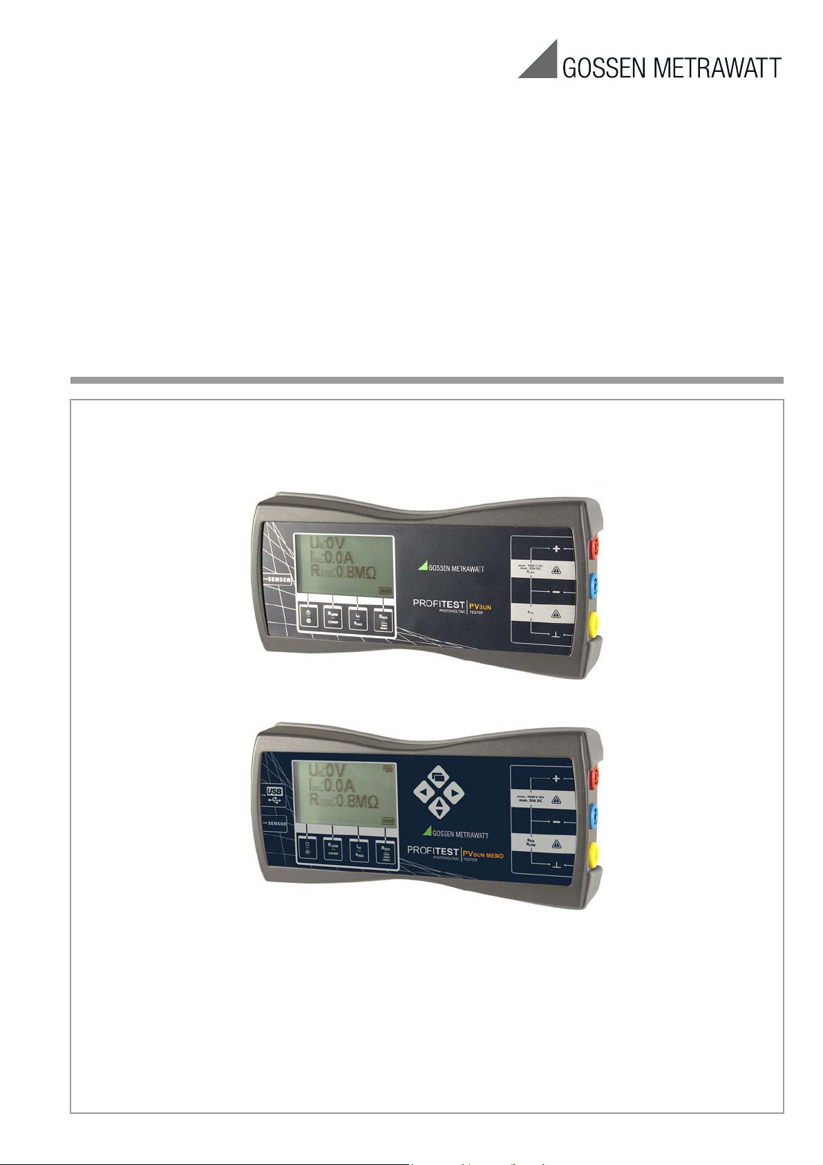
Operating Instructions
PROFITESTPVSUN and PVSUN MEMO
Test Instruments for Testing PV Modules
and Strings per DIN EN 62446 (VDE 0126-23)
3-349-672-15
11/3.16
These operating instructions are available
in this, as well as other languages, in PDF
format on the Internet at
www.gossenmetrawatt.com.
Page 2
Contents Page
Caution! Dangerous Voltage
Attention!
!
Warning!
Attention!
!
Note
!
2 Significance of Symbols
1 Scope of Delivery ............................................................. 2
2 Significance of Symbols .................................................. 2
3 Introduction ...................................................................... 3
4 Transport and Storage ..................................................... 3
5 Safety Precautions ........................................................... 3
6 Use for Intended Purpose ................................................. 3
7 Operating and Display Elements ..................................... 3
8 Initial Start-Up .................................................................. 4
9 Measurements ................................................................. 4
9.1 Testing Protective Conductor Continuity
per EN 62446 (VDE 0126-23) (> 200 mA) ......................................4
9.2 Polarity Test / Measuring Open Circuit Voltage U0
per EN 62446 (VDE 0126-23) ........................................................4
9.3 Measuring Short-Circuit Current I
9.4 Testing Insulation Resistance per EN 62446 ....................................5
9.5 General Insulation Resistance Measurement ....................................6
9.6 Ground Fault Test ..........................................................................6
per EN 62446 ..........................5
SC
10 Data Storage with PROFITEST PVsun memo .................... 7
10.1 Operating and Display Elements .....................................................7
10.2 Function Description ......................................................................7
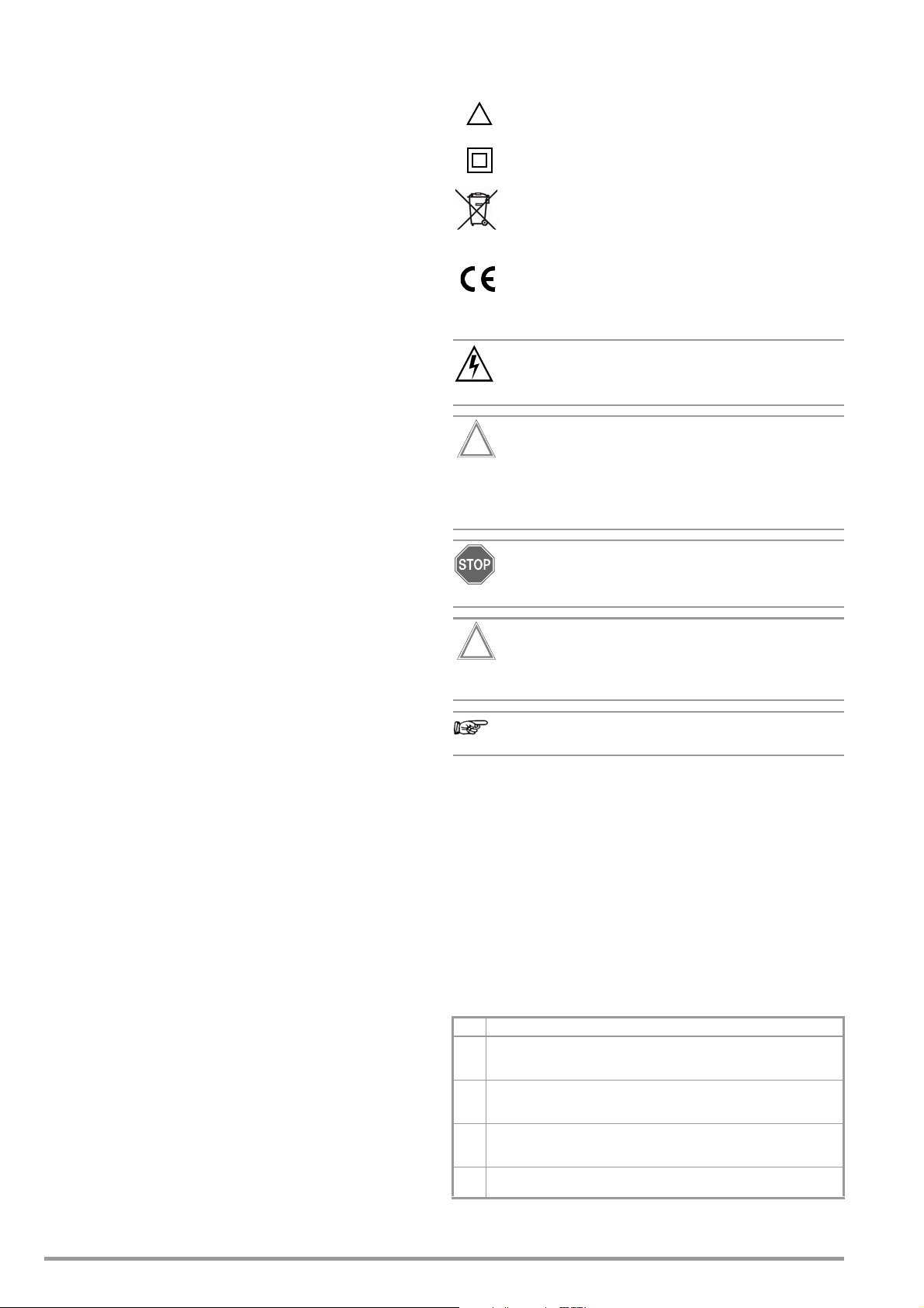
Meanings of Symbols on the Instrument
Warning concerning a point of danger
(attention: observe documentation!)
Protection class II device
(continuous, doubled or reinforced insulation)
This device may not be disposed of with the trash. Further information regarding the WEEE mark can be
accessed on the Internet at www.gossenmetrawatt.com by entering the search term “WEEE”.
EC mark of conformity
Meanings of Symbols in the Operating Instructions
While performing measurements in the presence of dangerous voltages, the PROFITEST PV
PROFITEST PV
safety gloves as it involves the risk of hazardous contact.
SUN MEMO should only be operated with PPE
SUN/
11 Application of PC Software .............................................. 8
11.1 System Requirements ....................................................................8
11.2 Installation ....................................................................................8
11.3 Initial Startup of the Device .............................................................8
11.4 Creation of Structures and Transfer to the Test Instrument ...............8
11.5 Reading Out and Exporting Test Data ..............................................8
12 Measurement of irradiation, temperature and inclination
with PROFITEST PVsun-sor (optional) .............................. 9
13 Characteristic Values ....................................................... 9
14 Maintenance .................................................................. 10
14.1 Battery Replacement ....................................................................10
14.2 Housing ......................................................................................10
15 Repair and Replacement Parts Service
Calibration Center* and Rental Instrument Service .............10
16 Product Support ............................................................. 10
1 Scope of Delivery
1 PROFITEST PVSUN or PROFITEST PVSUN MEMO
4 Batteries, 1.5 V IEC LR6 (AA)
3 Safety measurement cables, 1.5 m, red, blue and yellow:
banana plug – banana plug
1 Solar plug adapter, red: MC3 socket – banana socket
1 Solar plug adapter, red: MC4 socket – banana socket
1 Solar plug adapter, blue: MC3 plug – banana socket
1 Solar plug adapter, blue: MC4 socket – banana socket
1 Plug-on safety test probe with socket, red
1 Plug-on safety alligator clip with socket, yellow-gray
1 Carrying case with foam insert
1 Set of operating instructions
1 PC software (PROFITEST PV
can be downloaded from our website at:
www.gossenmetrawatt.com
1 USB interface cable (PROFITEST PV
SUN MEMO only)
SUN MEMO only)
Warning concerning a source of danger
Non-observance may result in distorted measurement
results.
Please observe!
Opening of Equipment / Repair
The equipment may be opened only by authorized service personnel to ensure the safe and correct operation of the equipment
and to keep the warranty valid.
Even original spare parts may be installed only by authorized service personnel.
In case the equipment was opened by unauthorized personnel,
no warranty regarding personal safety, measurement accuracy,
conformity with applicable safety measures or any consequential
damage is granted by the manufacturer.
Measuring Categories and their Significance per IEC 61010-1
CAT Definition
Measurements in other electrical circuits
0
which are not directly connected to the mains:
e.g. electrical systems in motor vehicles and aircraft, batteries etc.
Measurements in electrical circuits
II
which are electrically connected to the low-voltage mains:
via plug, e.g. in household, office and laboratory applications
Measurements in building installations:
III
Stationary consumers, distributor terminals, devices connected
permanently to the distributor
Measurements at power sources for low-voltage installations:
IV
meters, mains terminals, primary overvoltage protection devices
2 GMC-I Messtechnik GmbH
Page 3
3 Introduction
Caution! Dangerous Voltage
Attention!
!
Warning!
2
1
7
8
9
34 56
10
11
Battery full
Battery weak
These operating instructions contain information and directions
which are necessary for safe operation and use of the instrument.
Before using the instrument, the operating instructions must be
carefully read and all points contained therein must be followed
correctly. Non-observance of the operating instructions, as well
as warnings and directions included therein, may result in severe
injury to the user or damage to the instrument.
The
PROFITEST PV
modules. The terms used in these operating instructions to designate systems for generating electrical power from sunlight include:
solar system, photovoltaic system, PV system and the like.
Scope of Functions
• Voltage measurement to 1000 V DC
• Short circuit current measurement to 20 A DC
• Selection of insulation test voltage: 250, 500 or 1000 V DC
• Insulation measurement to 20 M with display of limit value
• Testing of protective conductor continuity
• Earth fault measurement
• Polarity check
• Backlit LCD panel
• Optional temperature measurement
SUN
is used for simple testing of solar cells and
The instrument may not be opened, dismantled or modified in any
way. The instrument may only be used with recommended
accessories. The use of unsuitable accessories is impermissible.
Trade association accident prevention regulations for electrical
systems and operating equipment must be adhered to during all
work with the instrument.
Do not allow the instrument to warm up due to exposure to direct
sunlight. Flawless functioning and a long service life cannot otherwise be assured.
The internal warming of the test instrument is measured
electronically. An inpermissible overheating is signalled
by ISC and °C in the display while further measurements
are being disabled. Allow the test instrument to cool
down before continuing measurements.
6 Use for Intended Purpose
The instrument may only be used under the conditions and for the
purposes for which it has been designed. In this respect, special
attention must be given to safety precautions, technical data
regarding ambient conditions and use in a dry environment.
4 Transport and Storage
Please retain the original packaging for subsequent shipment of
the instrument. Transport damages due to inadequate packaging
are excluded from the guarantee.
The instrument may only be stored in dry, closed rooms.
If the instrument is subjected to extreme temperature during
transport, it requires at least 2 hours for acclimatization before it is
switched on.
5 Safety Precautions
The instrument has been manufactured and tested in accordance
with IEC/EN 61010-1, “Safety requirements for electrical equipment for measurement, control and laboratory use”, and has been
shipped from the factory in flawless technical safety condition. In
order to assure that this condition is retained, the user must
observe the safety precautions included in these operating
instructions.
In order to prevent electrical shock, corresponding safety
precautions must be implemented when working with
voltages of greater than 120 V (60 V) DC or 50 V (25 V)
AC TRMS. In accordance with DIN VDE, these values
specify the limit for exposed (touchable) voltages (the values in parentheses apply to, for example, the fields of
medicine and agriculture).
Before each measurement, make sure that the measurement
cables and the measuring instrument are in flawless condition.
The measuring instrument may only be used within the specified
measuring ranges.
If the safety of the user is no longer assured, the instrument must
be removed from service and secured against unintentional use.
Safety of the user is no longer assured if the instrument:
• Demonstrates apparent damage
• No longer performs the desired measurements
• Has been stored for too long under unfavorable conditions
• Has been subjected to mechanical stressing during transport
Operating safety is no longer assured in the event of modification
or alteration. The instrument may only be opened by authorized
service technicians.
Never operate the instrument at a higher voltage than specified in
the technical data! The instrument may otherwise be destroyed or
permanently damaged.
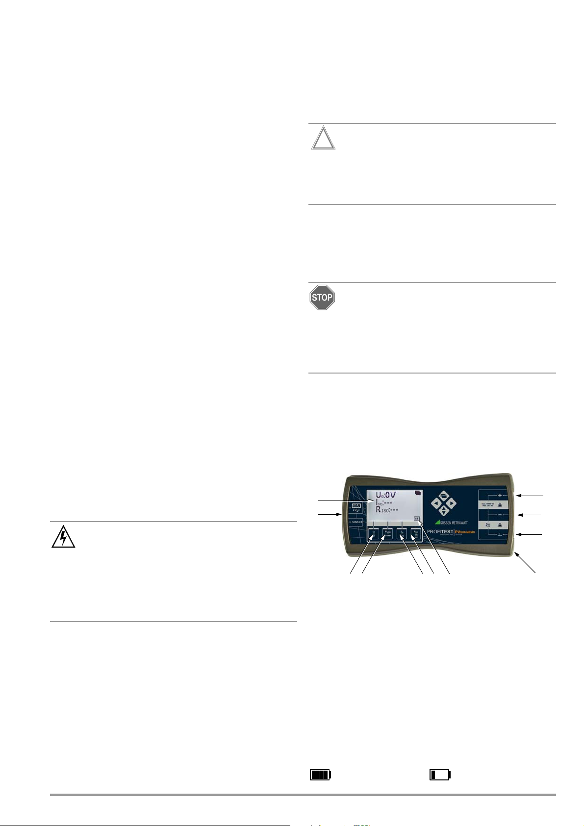
7 Operating and Display Elements
1 LCD panel with background illumination
2 Sensor socket for temperature measurement (optional)
3 On/Off switch / background illumination
4 Low-resistance measurement R
5 Short-circuit measurement ISC /
6 General insulation resistance measurement RISO /
7 Measurement input +
8 Measurement input – / insulation measurement / continuity test
9
10 Back: battery compartment
11 Battery level indicator
The instrument may not be operated at measuring category II, III and IV mains power circuits.
In accordance with EN 61010-1:2010, the instrument
has been designed without a rated measuring category,
and may only be used at direct voltage circuits with up to
1000 V without transient overvoltages.
/
measurement cable compensation COMP
insulation resistance measurement R
selection of insulation test voltage
Measurement input ground terminal / insulation measurement /
continuity test
LOW
ISO
per EN 62446
GMC-I Messtechnik GmbH 3
Page 4

8 Initial Start-Up
Attention!
!
Warning!
Caution! Dangerous Voltage
Warning!
Attention!
!
Warning!
0 0
U0: 0 V
R
LOW
: 0.1
R
ISO
: ---
The PROFITEST PVSUN is supplied with power from four AA batteries
(1.5 V IEC LR6). The batteries must be inserted before the instrument can be used.
➭ Remove the battery compartment lid on the back of the in-
strument by loosening the two Phillips head screws.
➭ Insert the batteries. Be sure to observe the polarity symbols
which are embossed into the floor of the battery compart-
ment.
➭ Replace the battery compartment lid and retighten the
screws.
The test instrument may only be operated with installed
battery compartment lid.
9 Measurements
The photovoltaic system’s plug connectors may not be
disconnected under load. Please observe warnings and
instructions provided by the plug manufacturer.
Solar modules continuously generate current, even when
shaded. Regulations for working with live voltage must
be adhered to during all work.
Disconnect all solar modules from the system before
performing the measurement.
Compensation for Measurement Cable Resistance
Ohmic measurement cable resistance can be subtracted from the
measurement results automatically. Proceed as follows in order to
determine the resistance offset value:
➭ Switch the PROFITEST PV
➭ Connect the measurement cables to the (–) and () sockets
and short-circuit the plug-on test probes.
➭ Press and hold the COMP key for at least 2 seconds in order to
trigger offset resistance measurement.
Symbol briefly appears.
The following display appears after completion of the measurement: R
The measured
internally and is subtracted from the actual result of all subsequent
measurements, until a new offset resistance value is acquired.
If the measured value of the connected cable is > 5 the symbol
briefly appears. Compensation of measurement cable resis-
tance is not possible.
R
OFFSET
LOW
: 0.0 .
SUN test instrument on.
value is not displayed, but is permanently stored
R
LOW
Protective Conductor Resistance Measurement
➭ Connect the (–) socket to a protective conductor terminal at
the solar module and the () socket to the equipotential bonding busbar.
➭ Briefly press the R
Measurement is started. The R
the protective conductor system appears at the display:
Example
LOW
key.
resistance value measured for
LOW
Switching the PROFITEST PVSUN On
➭ The test instrument is switched on by pressing the key.
➭ After the test instrument has been switched on, background
illumination can be switched on by briefly pressing the same
key once again.
➭ Briefly pressing the key a third time switches background illu-
mination back off.
➭ The test instrument can be switched off by pressing and hold-
ing the key for longer than 2 seconds.
9.1 Testing Protective Conductor Continuity
per EN 62446 (VDE 0126-23) (> 200 mA)
If a protective conductor or an equipotential bonding conductor is
included at the DC side of the photovoltaic system, its electrical
connection must be tested for continuity.
The connection to the main grounding terminal must also be tested.
Measurement results may be distorted due parallel connected impedances at load current circuits, as well as
equalizing current.
9.2 Polarity Test / Measuring Open Circuit Voltage U0 per EN 62446 (VDE 0126-23)
Disconnect the solar module under test from the system
before performing measurement.
➭ Connect the PROFITEST PV
4 GMC-I Messtechnik GmbH
with the help of suitable solar plugs.
SUN test instrument to the module
Page 5

➭ Switch the PROFITEST PVSUN test instrument on.
Note
Warning!
Warning!
Attention!
!
U0: 995 V
I
SC
: ---
R
ISO
: ---
U0: Pol
I
SC
: ---
R
ISO
: ---
!
U0: 985 V
I
SC
: 7.6 A
R
ISO
: > 20 M
U0: 870 V
I
SC
: 0.0 A
R
ISO
: ---
Uiso = 1000 V
The module’s open circuit voltage U
Example
In the case of incorrect polarity, a warning symbol
appears to the right of the voltage display.
Example
➭ Reverse polarity at the solar module and start testing over
again.
appears at the display.
0
9.3 Measuring Short-Circuit Current ISC per EN 62446
Disconnect the solar module under test from the system
before performing the measurement.
Disconnect the solar module under test from the system
before performing measurement.
Insulation measurement per EN 62446 is executed between short circuited (+) / (–) and () terminals.
➭ Connect the PROFITEST PV
with the help of suitable solar plugs.
➭ Connect the ground terminal at the PROFITEST PV
module frame.
➭ Switch the PROFITEST PVSUN test instrument on.
The module’s open circuit voltage U
SUN test instrument to the module
SUN to the
appears at the display.
0
Selecting the Test Voltage
➭ Press and hold the RISO/250V/500V/1000V key for at least 2
seconds.
The currently selected test voltage appears the display.
➭ Select the required insulation test voltage by briefly and re-
peatedly pressing the R
The last selected value is saved after a short period of time, and is
then cleared from the display.
Example
/250V/500V/1000V key.
ISO
➭ Connect the PROFITEST PV
with the help of suitable solar plugs.
➭ Switch the PROFITEST PV
The module’s open circuit voltage U
➭ Press the I
Open circuit voltage U
display:
Example
The (+) and (–) terminals at the solar module are short circuited
during the measurement, and momentary short-circuit current is
measured. Insulation resistance is measured at the same time
(see section 9.4).
SC
key.
SUN test instrument to the module
SUN test instrument on.
appears at the display.
0
and short-circuit current ISC appear at the
0
Executing the Insulation Resistance Measurement
➭ Press the ISC/R
display.
The (+) and (–) terminals at the solar module are short circuited
during the measurement, and momentary short-circuit current is
measured. Insulation resistance is measured at the same time.
key and read the measured value from the
ISO
9.4 Testing Insulation Resistance per EN 62446
GMC-I Messtechnik GmbH 5
Page 6

Minimum Permissible Limit Values for Insulation Resistance
Note
Warning!
Note
Note
Warning!
U0: 0 V
I
SC
: 0.0 A
R
ISO
: < 1 M
U0: 0 V
I
SC
: 0.0 A
R
ISO
: ---
Uiso = 1000 V
U0: 0 V
I
SC
: 0.0 A
R
ISO
: > 20 M
U0: 144 V
I
SC
: 0.0 A
Ue: 48 V
Relative to Insulation Test Voltage per EN 62446
System Voltage (U0
x 1.25)
< 120 V 250 V 0.5 M
120 to 500 V 500 V 1 M
> 500 V 1000 V 1 M
If the limit value is fallen short of,
<1M or < 0.5 M appears for R
Example
Test Voltage Limit Value
ISO
.
Example
Executing the Insulation Resistance Measurement
➭ Press the R
value from the display.
Example
/250V/500V/1000V key and read the measured
ISO
9.5 General Insulation Resistance Measurement
The PROFITEST PVSUN test instrument is additionally equipped with
system-independent insulation testing. This is helpful, for example, when testing systems or supply lines when no modules have
yet been installed. All insulations tests known to date can be performed.
The test object must be potential-free. Assure absence
of voltage with the help of a suitable measuring instrument,
for example the METRAVOLT 12D+L voltage tester.
If the minimum permissible limit value is fallen short of,
<1M or < 0.5 M appears for R
ISO
.
9.6 Ground Fault Test
If the test instrument recognizes an inadmissible, low insulation
value during I
sible ground fault.
If a ground fault occurs within the system, the error can be narrowed down on the basis of the voltage ratio.
Disconnect all solar modules from the system before
performing the measurement.
measurement, the instrument tests for pos-
SC/RISO
General insulation measurement is executed between
short circuited (–) and () terminals.
➭ Connect the (–) and () terminals at the PROFITEST PV
device under test.
➭ Switch the PROFITEST PV
SUN test instrument on.
Selecting the Test Voltage
➭ Press and hold the RISO/250V/500V/1000V key for at least 2
seconds.
The currently selected test voltage appears at the display.
➭ Select the required insulation test voltage by briefly and re-
peatedly pressing the R
The last selected value is saved after a short period of time, and is
then cleared from the display.
6 GMC-I Messtechnik GmbH
/250V/500V/1000V key.
ISO
SUN to the
➭ Connect the PROFITEST PV
suitable solar plugs.
➭ Connect the ground terminal at the PROFITEST PV
module frame.
➭ Switch the PROFITEST PVSUN test instrument on.
Momentary open circuit voltage is displayed.
At the same time, a second voltage (Ue) appears in the event of a
ground fault.
Example
SUN to the module with the help of
SUN to the
Page 7

10 Data Storage with PROFITEST PV
Note
Note
2
1
16
15
14
45 67
1383910 1112
Battery full
Battery weak
UOC=0V
I
SC
=---
R
ISO
=---
UOC=0V
I
SC
=---
R
ISO
=---
? OBJ:Objekt1 (1/1)
STR:String1 (1/1)
20.02.2012 10:00:00
U
OC
=0V ISC=0.0A
R
ISO
=>20MΩ R
low
>10Ω
E=--- T=--=--- Ib=---
►
STR:String West (1/1)
20.02.2012 10:00:00
U
OC
=0V ISC=0.0A
R
ISO
=>20MΩ R
low
>10Ω
E=--- T=--=--- Ib=---
►
SUN MEMO
The PROFITEST PVSUN MEMO test instrument is equipped with an
internal memory for the storage of 10,240 data records. The
stored data can be read out via a USB port for subsequent evaluation from a PC. Furthermore, the included PC software allows for
the creation of individual test structures.
10.1 Operating and Display Elements
1 LCD panel with background illumination
2USB interface
3 Sensor socket for temperature measurement (optional)
4 ON/OFF switch / background illumination
5 Low-resistance measurement R
compensation COMP
6 Short-circuit measurement I
measurement R
General insulation resistance measurement
7
per EN 62446
ISO
selection of insulation test voltage
/ measurement cable
LOW
/ insulation resistance
SC
R
/
ISO
8 Battery level indicator
9 Selection of objects or strings
10 Switch between display / activation of storage function
11 Switch between objects and strings
12 Selection of objects or strings
13 Back: battery compartment
14 Measuring input ground terminal () /
insulation measurement / continuity test
15 Measuring input – / insulation measurement / continuity test
16 Measuring input +
10.2 Function Description
Switch between standard measurement display
and storage display
Standard measurement
display without memory
function
The storage function is
not activated before
switch-over to storage
display, see screenshot
below.
Standard measurement
display with activated
storage function.
If a measurement is performed, the measured
values are stored under
the object and string
selected before.
Stored values are overwritten in the activated object/
string.
Storage display
►OBJ:Object1 /
STR:String1 are active.
Presently, one object (1/1)
and one string (1/1) have
been created.
Date / time
Measured values currently stored (meaning of abbreviations):
U
Open-circuit voltage
OC
ISC Short-circuit voltage
Insulation resistance
R
ISO
Low-resistance measurement
R
low
E Solar irradiation (optional with PROFITEST PV SUN-SOR)
T Module temperature (optional with PROFITEST PV
SUN-SOR)
Inclination angle of module (optional with
PROFITEST PV
Operating current (optional with current clamp)
I
b
? OBJ:Testkunde (1/1)
SUN-SOR)
(Alphanumeric) names
can be assigned to
objects and strings with
the PC software
(e. g. OBJ: test client).
GMC-I Messtechnik GmbH 7
Switch to previous object or string
Switch to next object or string. If the last object or
string is reached, a new object or a new string
can be created by pushing this key (> 2 s).
Switch between objects and strings. Symbol ►
indicates whether objects or strings are active
(e. g.: ►OBJ:Object1).
If objects and strings are extended in the test instrument,
it is not possible to assign alphanumeric characters.
There is only an incrementation instead (gradual increase
by one character each).
Page 8

11 Application of PC Software
Attention!
!
Individual test structures can be created at the PC with the
included software. This structure makes it possible to assign
measurements to the objectes and strings of different units and
buildings. For use at the construction site, the respective test
structures are first transferred to the test instrument via the USB
interface. After performing the measurements, the test instrument
is read out and the structures are represented together with the
measured values in tabular form.
11.1 System Requirements Hardware
• Processor and RAM see minimum requirements of the
respective operating system
• VGA monitor with a resolution of at least 1024 x 768 pixels
• Hard disc with at least 12 MB available memory
• Both input devices (mouse / keyboard)
• One or several USB interfaces
Operating System – Software
• Windows XP, Windows Vista, Windows 7 or 8
11.2 Installation
The latest version of the PC software PV SUN MEMO Control
Center is available for free download as a zip file from our homepage:
http://www.gossenmetrawatt.com
Products Electrical Testing Testing of Electr. Installations
PROFITEST PV
The zip file must be unpacked and stored in a directory. The setup
file has been placed in this directory. Double-click on the setup to
launch the installation routine. An assistant guides you through
the complete installation.
The installation directory and the program file can be selected at
your own discretion.
SUN MEMO
11.4 Creation of Structures and Transfer to the Test Instrument
Create a new structure by clicking on icon „New“ under „Measuring Data“.
Clicking on „New“ deletes the structures and measuring
data indicated before.
You can freely extend a structure by clicking on icon „+Object“ or
„+String“. Repeat these steps until you have created the
requested structure. By clicking on the object or string denomination you can change the name at your discretion (alphanumeric).
The number of possible data records = objects which can be
transferred to the test instrument, amounts to approx. 10,000.
Click on the „Write“ icon for transferring the data records to the
test instrument.
Setting of Date/Time
Date/time in the test instrument are synchronized automatically
upon importing the file (structure) from the PC.
11.5 Reading Out and Exporting Test Data
After performing the measurements, click on icon „Read“ for
reading out the data records (structures and measured values)
from the test instrument. The structures are presented in tabular
form together with the measuring data. The column width of the
header elements can be adjusted by dragging the column border
lines to the right or to the left.
11.3 Initial Startup of the Device
➭ Switch on the test instrument and connect it with your PC.
Windows announces that a device has been connected and that
the driver must be installed.
➭ Select manual installation „Install software from a list or a
specific source“.
➭ Click on „Search“ in the next menu and select directory
„C:\Programme\PVSUN MEMO Control Center\USB Driver“
(unless you have changed the installation path).
➭ Ignore the message regarding unknown provenance of the
software.
➭ Complete the driver installation.
➭ Please check: „PVSUN MEMO Memory (COMxx)“ should be
displayed in the device manager under Connections.
➭ Start the installed program „PVSUN MEMO Control Center“.
➭ Click on icon „Search device“.
For storage and subsequent evaluation of the measuring data,
press icon „Export“. The data are written into a csv file so that
they can be exported to other programs, such as Microsoft Excel.
Deleting of Structures
The structural contents are automatically deleted when an empty
structure is transmitted to the test instrument.
8 GMC-I Messtechnik GmbH
Page 9

12 Measurement of irradiation, temperature and
Warning!
U0: 0 V
I
SC
: 0.0 A
R
ISO
: ---
: 1.0
E: 1000W/m² T:25°C
inclination with PROFITEST PVSUN-SOR (optional)
Hot surfaces may cause burns.
➭ Connect the PROFITEST PV
➭ Place the PROFITEST PV
voltaic module.
➭ Switch the PROFITEST PVSUN / PROFITEST PVSUN MEMO on.
The display shows the monentary irradiation, the surface tem-
perature and the inclination angle of the modules.
Example:
SUN-SOR to the sensor socket.
SUN-SOR onto the surface of the photo-
Characteristic Values PROFITEST PVSUN-SOR
Irradiance Measuring range 0 … 2000 W/m²
Resolution 1 W/m²
Cell monocrystalline, approx. 27 x 16 mm
Accuracy 15% (T = 25 C)
Temperature
Measurement Measuring range –55…99 C
Inclination Angle Measuring range 0 … 90
Cable length approx. 10 m
Power Supply via PROFITEST PV
Resolution 1 C
Accuracy 1 C
Resolution 0,1
Accuracy 1
SUN /
PROFITEST PVSUN MEMO
approx. 3,3 V / 3,1 mA
Dimensions approx. 120 x 65 x 27 mm
Weight approx. 150 g
13 Characteristic Values
Voltage Measurement U0
Measuring range 0 to 100 V to 1000 V DC
(no transient voltages)
Resolution 1 V
Accuracy (2% rdg. + 1 d)
Current (direct)
Measuring range 0 to 20 A DC
Voltage range 2 to 1000 V DC
Resolution 0.1 A
Accuracy (1% rdg. + 1 d)
Overcurrent protection
Max. 24 A (shutdown of internal circuit)
Insulation Resistance Measurement RISO
Test voltage 250 V DC 500 V DC 1000 V DC
Measuring range 0.5 M
Resolution 0.1 M 1 M 1 M
Accuracy (1% rdg. + 1 d) (1% rdg. + 2 d) (1% rdg. + 2 d)
Limit value > 0.5 M
No. of measurements Approx. 1000 (with battery set per IEC LR6)
to 1 M 1 M to 20 M 1 M to 20 M
> 1 M > 1 M
Earth Fault Measurement
Measuring range 0 to 1000 V DC
Resolution 1 V
Accuracy (5% rdg. + 1 d)
Low-Resistance Measurement
Measuring range 0 to 10
Test current > 200 mA
Resolution 0.1
Accuracy (1% rdg. + 1 d)
No. of measurements Approx. 500 low-resistance measurements
(batteries: 1.5 V per IEC LR6)
Display
LCD Backlit multiple display
Dot matrix: 128 x 64 pixels
Reference Conditions
Ambient temperature +23 C 2K
Relative humidity 40 to 75%
Battery voltage 6 V 1V
Ambient Conditions
Operating
temperature 0 to +40 C
Storage temperature –10 C to 60 C
Relative humidity < 80%, no condensation allowed
Elevation Max. 2000 m above sea level
Power Supply
Batteries 4 ea. 1.5 V IEC LR6, AA, AM3, MN1500
Consumption Approx. 20 μA when switched off
Approx. < 30 mA during normal operation
Approx. 190 mA with backgr. illumination
Electrical Safety
Voltage range 1000 V
Electromagnetic Compatibility (EMC)
EMC directive EMC 2004/108/EC
Basic standard EN 61326-1:2006
Data Memory (PROFITEST PVSUN MEMO only)
Storage capacity max. 10,240 data records
Memory type non-volatile flash memory (data are pre-
served even if batteries are depleted)
Data Interface (PROFITEST PVSUN MEMO only)
Type USB 2.0 (USB 2.0 full speed (12 Mbps)
Connection mini-USB type B (5-pin)
Cable USB 2.0 cable (A plug | Mini-B-)
compatible)
Mechanical Design
Protection Housing: IP 42
Dimensions 209 x 98 x 35 mm
Weight Approx. 500 g with batteries
per DIN VDE 0470 part 1/EN 60 529
GMC-I Messtechnik GmbH 9
Page 10

14 Maintenance
Pb Cd Hg
14.1 Battery Replacement
If the battery level indicator displays only minimal
remaining battery capacity (only one segment
appears, see figure at right), the batteries must be
replaced.
➭ Switch the instrument off and disconnect it from all measuring
circuits.
➭ Remove the battery compartment lid on the back of the in-
strument by loosening the two Phillips head screws.
➭ Remove the depleted batteries.
➭ Insert new batteries. Be sure to observe the polarity symbols
which are embossed into the floor of the battery compartment.
➭ Replace the battery compartment lid and retighten the
screws.
After inserting new batteries, all four segments
should appear at the display.
14.2 Housing
No special maintenance is required for the housing. Keep outside
surfaces clean. Use a slightly dampened cloth for cleaning. Avoid
the use of cleansers, abrasives or solvents.
Return and Environmentally Sound Disposal
The instrument is a category 9 product (monitoring and control
instrument) in accordance with ElektroG (German electrical and
electronic device law). This device is subject to the RoHS directive. Furthermore, we make reference to the fact that the current
status in this regard can be accessed on the Internet at
www.gossenmetrawatt.com by entering the search term WEEE.
In accordance with WEEE 2012/19/EU and ElektroG, we
identify our electrical and electronic devices with the symbol
in accordance with DIN EN 50419 which is shown at the
right. Devices identified with this symbol may not be disposed of
with the trash. Please contact our service department regarding
the return of old devices (see address in section 15).
15 Repair and Replacement Parts Service
Calibration Center* and Rental Instrument Service
If required please contact:
GMC-I Service GmbH
Service Center
Thomas-Mann-Strasse 16-20
90471 Nürnberg • Germany
Phone: +49 911 817718-0
Fax: +49 911 817718-253
e-mail service@gossenmetrawatt.com
www.gmci-service.com
This address is only valid in Germany.
Please contact our representatives or subsidiaries for service in
other countries.
* DAkkS Calibration Laboratory for Electrical Quantities
D-K-15080-01-01 accredited per DIN EN ISO/IEC 17025:2005
Accredited measured quantities: direct voltage, direct current values, DC resistance, alternating voltage, alternating current values,
AC active power, AC apparent power, DC power, capacitance,
frequency and temperature
16 Product Support
If required please contact:
GMC-I Messtechnik GmbH
Product Support Hotline
Phone: +49-911-8602-0
Fax: +49 911 8602-709
e-mail: support@gossenmetrawatt.com
If the batteries used in your instrument are depleted, they must be
disposed of properly in accordance with valid national regulations.
Batteries may contain pollutants and heavy metals such as lead
(Pb), cadmium (Cd) and mercury (Hg).
The symbol at the right indicates that batteries must not
be disposed of with the trash, and must be brought to a
designated collection point.
Edited in Germany • Subject to change without notice • PDF version available on the Internet
GMC-I Messtechnik GmbH
Südwestpark 15
90449 Nürnberg
• Germany
Phone: +49 911 8602-111
Fax: +49 911 8602-777
e-mail: info@gossenmetrawatt.com
www.gossenmetrawatt.com
 Loading...