

Page 1
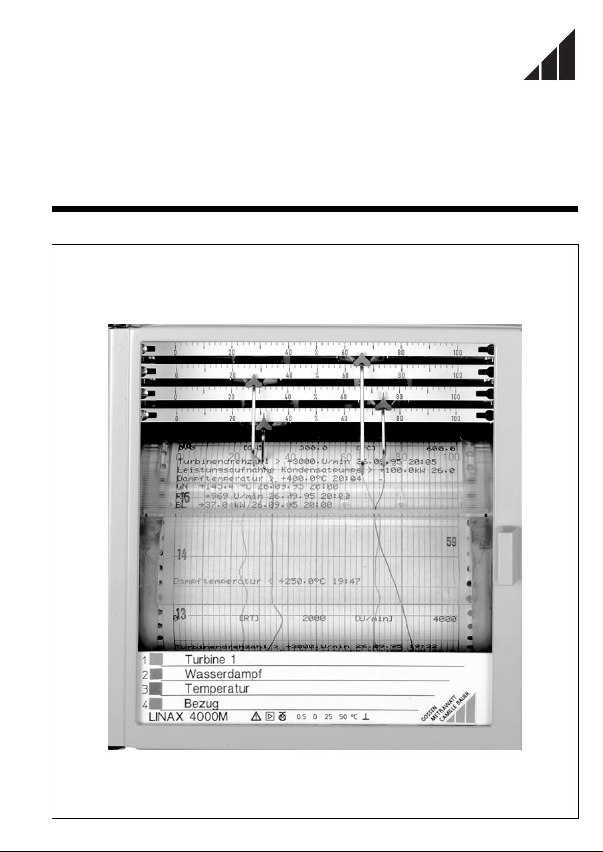
Operating Instructions
GOSSEN
GOSSEN
METRAWATT
METRAWATT
CAMILLE BAUER
CAMILLE BAUER
LINAX 4000M
14082B
1 / 12.95
Page 2

Contents
Page
1 Installation and startup . . . . . . . . . . . . . . . . . . . . . . . . . . . . . 3
1.1 Scope of delivery . . . . . . . . . . . . . . . . . . . . . . . . . . . . . . 3
1.2 Choosing the mounting site . . . . . . . . . . . . . . . . . . . . . . 3
1.3 Installation. . . . . . . . . . . . . . . . . . . . . . . . . . . . . . . . . . . . 3
1.4 Connection. . . . . . . . . . . . . . . . . . . . . . . . . . . . . . . . . . . 4
1.4.1 Connecting the input signals . . . . . . . . . . . . . . . . . 4
1.4.2 Connecting the power supply . . . . . . . . . . . . . . . . 4
1.5 Chart loading . . . . . . . . . . . . . . . . . . . . . . . . . . . . . . . . . 5
1.5.1 Recording table for roll chart . . . . . . . . . . . . . . . . . 5
1.5.2 Recording table for fanfold chart . . . . . . . . . . . . . . 5
1.6 Installing the fiber pen insert / print insert . . . . . . . . . . . . 6
1.7 Switching the recorder on. . . . . . . . . . . . . . . . . . . . . . . . 6
1.8 Positioning the recording chart . . . . . . . . . . . . . . . . . . . . 6
2 Operation. . . . . . . . . . . . . . . . . . . . . . . . . . . . . . . . . . . . . . . 7
2.1 Removing the recording chart. . . . . . . . . . . . . . . . . . . . . 7
2.2 Removing the recording chart from the take-up roll. . . . . 7
2.3 Changing the chart speed. . . . . . . . . . . . . . . . . . . . . . . . 7
2.4 Standby function. . . . . . . . . . . . . . . . . . . . . . . . . . . . . . . 7
3 Reconfiguration . . . . . . . . . . . . . . . . . . . . . . . . . . . . . . . . . . 8
3.1 Changing the measuring ranges . . . . . . . . . . . . . . . . . . . 8
3.1.1 Hardware matching by means of jumpers. . . . . . . 8
3.2 Replacing scales. . . . . . . . . . . . . . . . . . . . . . . . . . . . . . . 9
3.3 Replacing the label for the measuring points. . . . . . . . . . 9
4 Maintenance. . . . . . . . . . . . . . . . . . . . . . . . . . . . . . . . . . . . 10
4.1 Fuse replacement . . . . . . . . . . . . . . . . . . . . . . . . . . . . . 10
Important information for your safety!
It must absolutely be read and followed!
A condition of correct and safe operation of the continuousline recorder LINAX 400M is that it is transported and stored
in a suitable manner, competently installed and started as
well as correctly operated and carefully serviced.
Only those persons must work on the recorder who ar e familiar with installation, startup, operation and servicing of comparable equipment and who have the qualification required
for their work.
The contents of these operating instructions and the safety
notes affixed to the unit are to be observed.
The regulations, standards and directives mentioned in these
operating instructions are for the Federal Republic of Germany. When using the recorder in other countries, relevant
national rules must be followed.
The recorder is constructed and tested according to
DIN EN 61 010-1 "Safety requirements for electr onic measuring instruments", it left the factory in safe and proper condition. To maintain this condition and to ensure safe operation,
the safety notes in these operating instructions with the
heading "Caution" must be followed. Otherwise, persons
could be endangered and the unit itself as well as other
equipment and facilities could be damaged.
If the information contained in these operating instructions
should not be sufficient in certain cases, the GOSSENMETRAWATT Service will be glad to provide further information.
5 Technical data . . . . . . . . . . . . . . . . . . . . . . . . . . . . . . . . . . 11
6 Packing . . . . . . . . . . . . . . . . . . . . . . . . . . . . . . . . . . . . . . . 14
Reference symbols in the text
<Key> Designation of the keys in the display and control
panel
Display Non-flashing presentation on the display
Display Flashing presentation on the display
The information "right", "left" or "top", "bottom" – unless otherwise stated – is on the understanding that the viewer looks at the
front.
Supplementary documents
Parameterizing instructions LINAX 4000M 14083B
Interface description LINAX 4000M 14084B
Applications and brief description
The LINAX 4000M is a microprocessor-controlled co ntinuous-line
recorder. It comes in two different versions:
– 1 to 4 line channels,
– 1 to 3 line channels and a printer channel.
The printer channel permits the recording of a measured value
and generates text printouts. The measuring channels are electrically isolated from each other and are floating. The recorder is
connected to transducers and to sensors such as thermocouples
or resistance thermometers. Standard temperature sensor curves
are stored in the firmware of the recorder and linearized with high
accuracy.
In the version "Standard measuring range", the recorder is
matched to the measuring task by means of keys of the display
and control panel or via the RS-485 interface. The version "Universal measuring range" requires additional hardware matching
by means of jumpers.
2 GOSSEN-METRAWATT
Page 3
1 Installation and startup
1.1 Scope of delivery
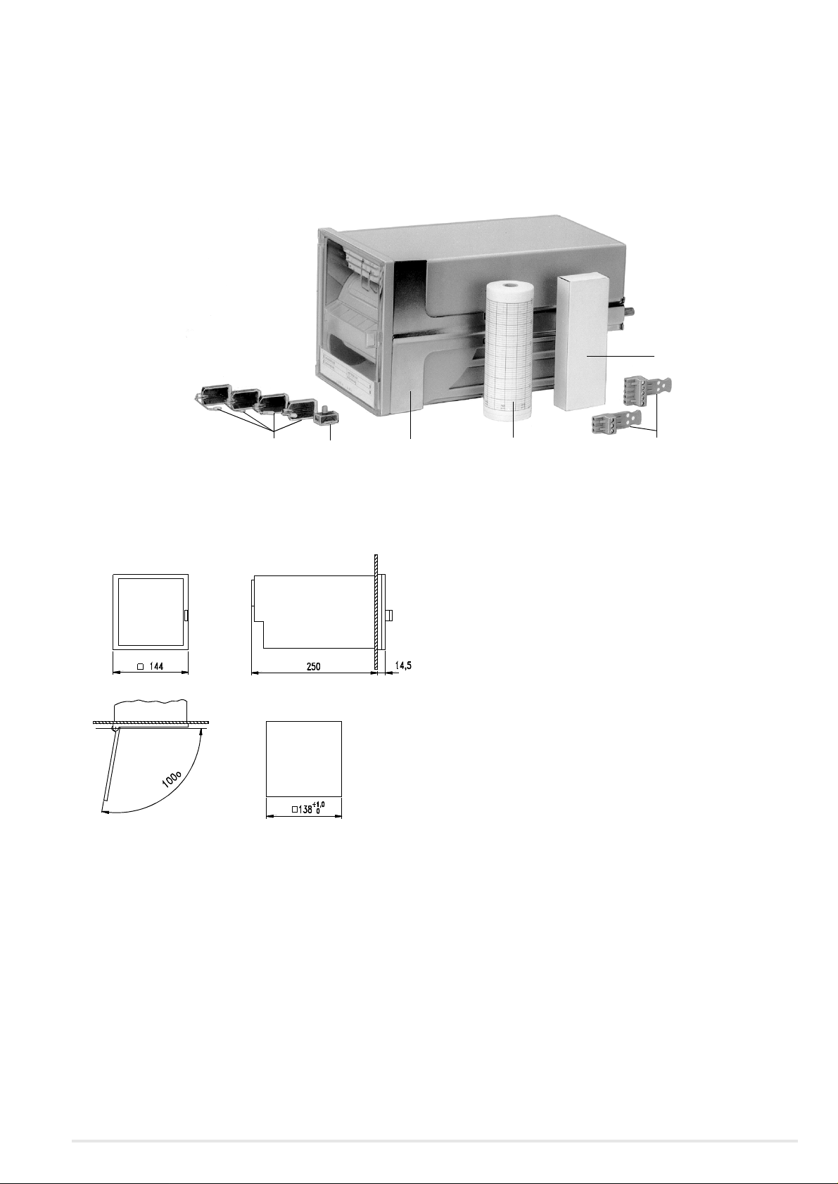
(see figure 1)
The continuous-line recorder LINAX 4000M comes with:
– 1 copy of operating instructions
Be Fastener
De Print insert (Option)
Fe Fiber pen inserts
Fp Fanfold chart
Sk Screw-plug terminals
Sr Chart roll
– 2 fasteners Be
– 1 fiber pen insert Fe per measuring channel
–1 print insert De (Option)
– 1 pack of fanfold chart Fp or 1 roll chart Sr
– 24 jumpers for universal version
– Depending upon the order, the respective number of screw-
plug terminals Sk, Sub-D plug, 9-pin, and reading ruler(s).
Fp
Fe
Figure 1 Scope of delivery of the LINAX 4000M
De
1.2 Selecting the mounting site
Panel cutout
Figure 2 Dimensional drawing LINAX 4000M (dimensions in mm)
Be Sr
Sk
1.3 Installation
(see figure 2 and figure 3)
Installation in switchboards
1. Insert the recorder into the switchboard from the front.
2. At the sides of the case, slide the fasteners Be into the guide
grooves (see figure 3).
Note
The fasteners Be are suited for side-by-side mounting in horizontal or vertical direction.
3. After aligning, equally tighten the fasteners Be.
Position of use Inclination to the side –30°... 0 ... + 30°
Inclination to the rear 20°
Inclination to the front 20°
Ambien t temp. 0 ... 50 °C
Relative humidity ≤ 75 % annual average,
max. 85 %.
Prevent dewing!
Figure 3 Mounting the fasteners
GOSSEN-METRAWATT 3
Page 4
Installation in grid frames
1. Fasten 4 each centering angle bracket (Ordering number
A416A) on the grid frame.
2. Slide the fasteners Be into the guide grooves at the sides of the
case (see figure 3).
3. After alignment, equally tighten the fasteners Be.
1.4 Connection
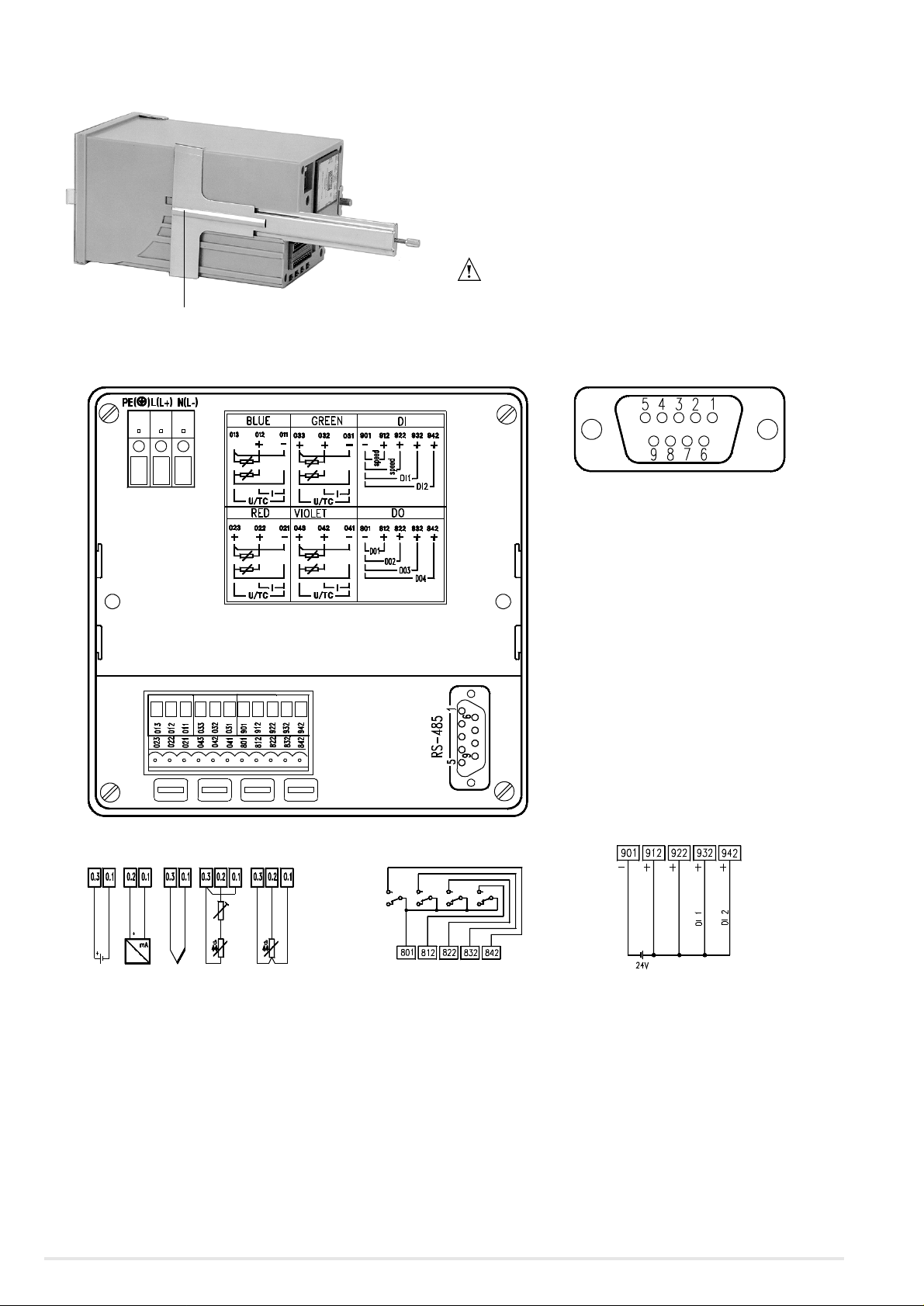
(see figure 4)
Caution
Be Fastener
The connection between the protective conductor connection and a protective conductor must be made prior to all other connections.
RS-485 interface
Pin 1: Shield
Pin 3: RXD (+)
Pin 5: Gnd (reference potential)
Pin 6: +5 V
Pin 8: RXD (-)
For bus operation:
The voltage + 5V at pin 6 is required when
the LINAX 4000M is used as bus end device.
The shield is attached to a plug-type
connector on the recorder case.
Signal inputs Limits
Figure 4 Rear panel and wiring diagrams
1.4.1 Connecting the input signals
• Fasten the signal leads in the screw-plug terminals, maximum
cross section 2 × 1mm
2
.
Chart speed circuit (terminals 901, 912, 922
Binary inputs = depending upon the parameterization
for event markers / activation of text print
(terminals 901, 932, 942)
speed 2
speed off
The recorder must only be operated in installed condition.
A power line connection switch of sufficient switching capacity, which
permits all-pole disconnection of the recorder from the power line, must
be provided within reach of the mounting site. It must not annul the protective effect of the protective conductor.
4 GOSSEN-METRAWATT
Page 5
1.5 Chart loading
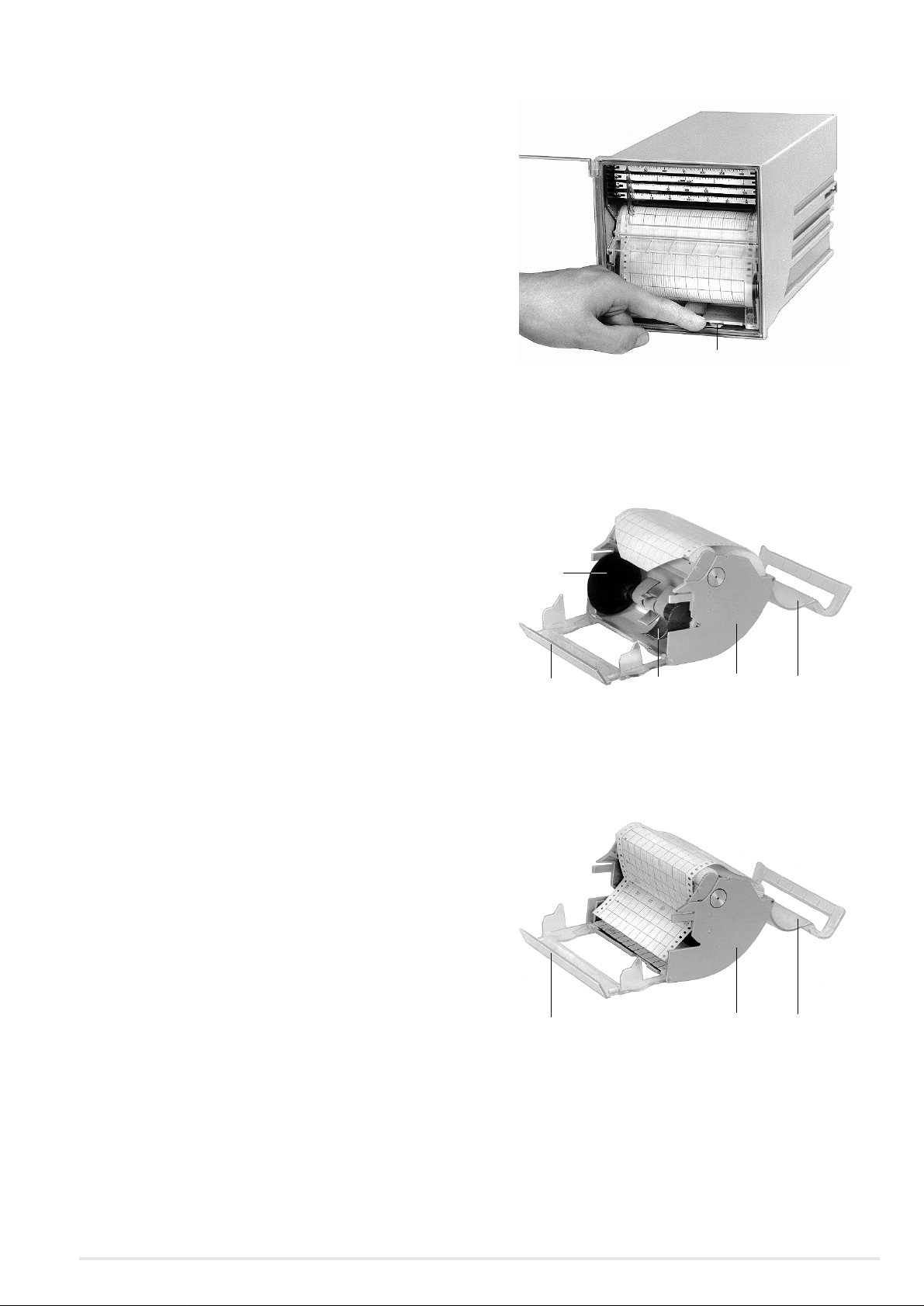
Figure 5 Unlocking the recording table
Eh Unlocking lever
Ar Take-up roll
Ff Guide spring
Pa Paper holddown device
Pf Chart guide
Pm Chart compartment
1.4.2 Connecting the power supply
• Fasten the power supply lines, max. cross section 1 × 4mm2
or 2 × 1.5 mm
the protective conductor must at least correspond to the cross
section of the line power cable.
2
, in the screw terminals. The cross section of
Ar
Pf Ff Pm Pa
Figure 6 Recording table for roll chart
Pa Paper holddown device
Pf Chart guide
Pm Chart compartment
Pf Pm Pa
Figure 7 Recording table for fanfold chart
GOSSEN-METRAWATT 5
Page 6

1.6 Installing the fiber pen insert / print insert
1.5.1 Recording table for roll chart
(see figure 5 and figure 6)
1. Unlock the recording table: Press the unlocking lever Eh downwards (see figure 5). The recording table tilts to the front.
Remove the recording table.
2. Unfold the paper holddown device Pa.
3. Place the chart roll into the chart compartment Pm.
4. Pull the front end of the chart up to the pin platen and place
the perforation onto the pins of the platen. Make sure chart
and pin platen are in parallel!
5. Fold the paper holddown device Pa back.
6. Unfold the chart guide Pf.
7. Insert the take-up roll Ar
8. Fold the chart guide Pf back.
Note
When the recording table has been inserted into the recorder,
the chart automatically winds onto the take-up roll.
9. Swing the recording table into the chassis until it engages.
1. Fold the scales up.
2. Install the fiber pen insert / print insert according to figure 8.
Figure 8 Installing the fiber pen ins e r t / prin t insert
1.5.2 Recording table for fanfold chart
(see fig. 5, fig. 6 and fig. 7)
When changing the recording table for roll chart to fanfold chart,
remove the guide spring Ff (see figure 6).
1. Unlock the recording table: Press the unlocking lever Eh downwards (see figure 5). The recording table tilts to the front.
Remove the recording table.
2. Unfold the paper holddown device Pa.
3. Place the fanfold pack into the chart compartment Pm.
4. Unfold the chart guide Pf.
5. Pull the front end of the chart up to the pin platen and place
the perforation onto the pins of the platen. Two folded layers
must rest on the bottom of the chart compartment. Make sure
chart and pin platen are in parallel!
6. Fold the paper holddown device Pa back.
7. Fold the chart guide Pf back.
8. Swing the recording table into the chassis until it engages.
Figure 9 Display and contro l panel
It is easier to install the fiber pen inserts and the print insert when
the recorder is switched on.
1. Unlock the recording table: Press the unlocking lever Eh downwards (see figure 5). The recording table tilts to the front.
2. Remove the recording table.
3. Press <▲>. The measuring systems travel to the park position.
4. Fold the scales up.
5. Install the fiber pen inserts and the print insert.
6. Fold the scales down.
7. Press < >.
8. Swing the recording table into the chassis until it engages.
6 GOSSEN-METRAWATT
Page 7

1.7 Switching the recorder on
Caution
Prior to switching the power supply on, verify that the operating voltage
of the recorder (see nameplate) and the supply voltage agree.
A power line connection switch of sufficient switching capacity,
which permits all-pole disconnection of the recorder from the
power line, must be provided within reach of the mounting site. It
must not annul the protective effect of the protective conductor.
Date and time are buffered via a capacitor (Super Cap). After
longer periods without auxiliary voltage (e.g. when in stock), date
and time are reset to a default value. At the next start, a note
appears on the display (error message E150X). Date and time
must then be set newly (see parameterizing instructions, orde ring
number 14083).
1.8 Positioning the recording chart
(see figure 10)
1. Press the lower grip boards of the recording table to the rear.
The recording chart is transported with incre ased speed in the
direction of flow.
2. Release the grip boards when the desired time line is reached.
Figure 10 Positioning the recording chart
2Operation
2.1 Removing the recording chart
(see figure 11)
GOSSEN-METRAWATT 7
Page 8

Figure 11 Removing the recording chart
2.2 Removing the rec. chart from the take-up roll
(see figure 12)
The recording table may be left in the unit when removing the
chart.
Recording table for chart rolls
1. Unfold the chart guide downwards.
2. Remove the take-up roll.
3. Eventually separate the chart at the tear-off edge.
Recording table for fanfold chart
1. Unfold the chart guide downwards.
2. Remove the recording chart.
3. Eventually separate the chart at a fold.
Note
Two folded layers of the chart must rest in the chart compartment.
1. Turn the flange without drive pinion through 45° and remove it
from the take-up roll.
2. Grip the chart as shown in figure 12 and pull it off the axle.
3. Re-attach the right flange to the take-up roll and secure it by
turning it through 45° .
4. Insert the take-up roll into the recording table. The drive pinion
must be on the right side.
5. Close the chart guide.
Figure 12 Removing the recording chart from the take-up roll
2.3 Changing the chart speed
When the recorder is fitted with the option "Limit monitor and
binary inputs", two chart speeds are externally selectable. The
desired values for speed 1 and speed 2 are selected in parameterization mode (see parameterizing instructions 14083).
Speed 1 is active after the recorder is switched on.
Speed 2 becomes active by applying a voltage of 24 V DC
between terminals 901 (–) and 922 (+).
2.4 Standby function
When the recorder is fitted with the option "Limit monitor and
binary inputs", the recorder can be switched to standby. This
requires a voltage of 24 V DC to be applied between terminals
901 (–) and 912 (+).
In standby mode, the chart speed is switched off and is 1 mm/h
(depending on the parameterization). The measuring systems are
at the beginning of the scale. Processing of measured data and
limit monitoring are active. When a limit is violated, or when the
applied voltage is disconnected, the standby mode is inactivated.
The recorder starts to record.
8 GOSSEN-METRAWATT
Page 9

3 Reconfiguration
3.1 Changing measuring ranges
3. Unplug the plug to the measuring systems (max. 1...4) and the
plug for the printer channel.
4. Remove the electronic unit (see figure 14).
Standard version
In the version "Standard measuring range", the recorder is
matched to the measuring task via keys of the display and control
panel or via the RS-485 interface. See parameterizing instructio ns
14083.
Universal version
In the version "Universal measuring range", the recorder is
matched to the measuring task via keys of the display and control
panel or via the RS-485 interface. See parameterizing instructio ns
14083.
In addition, hardware matching by means of jumpers is required
on the channel card.
3.1.1 Hardware matching by means of jumpers
(see figure 13))
Ah Locking screw
Removing the channel card (lower circuit board)
1. Undo 4 screws SI (see figure 15).
2. Arrange the jumpers on the wiring side of the channel card in a
channel-specific manner. Figure 16 shows the jumper fields
that are assigned to the channels (X3...X6).
3. Arrange the jumpers in line with the desired measuring mode
and the desired nominal measuring range (see figure 17).
4. Fasten the channel card Kk with the 4 screws SI (see figure 15).
5. Restore the plug connection to the measuring systems.
6. Insert the electronic unit into the recorder.
– Securely engage the locking lever Vh.
7. Slide the carrier of the measuring systems into the case and
tighten th e l oc k i n g sc rew As (see figure 13).
8. Switch the power supply on and parameterize the desired
measuring ranges (see parameterizing instructions 14083).
Sl
Sl
Vh Locking lever
Figure 13
Dk Display card
Ck CPU card
Kk Channel card
Ck
Figure 14 Electronic unit removed (rear view)
Dk
Kk
Sl
Figure 15 Undo the screws SI of the channel card (bottom view)
ANALOG-UNIVERSAL
X3 X4 X5 X6
Channel blue
Channel red
Channel green
1 21 21 21 2
Channel violet
X1
X2
Sl
Figure 16 Arrangement of the jumper fields
Removing the electronic unit
1. Undo the locking screw As (see figure 13) and pull the carrier of
the measuring systems about 2 cm to the front.
2. Lift the locking lever Vh (see figure 13) and at the same time
pull the assembly group to the front.
GOSSEN-METRAWATT 9
Page 10

Current
–20...20 mA
12 12 12 12
Current
0...20 mA
4...20 mA
Thermocouple
Ty pe B,R
S,T
Type E,J, K
L,N, U
7. Check the measuring system zero with beginning of scale.
a. Remove the recording table.
b. Press <↵>. "SYS" is displayed.
The measuring systems travel to electrical zero.
c. Align scale with pointer and tighten the scale screw.
d. Insert the reco rding table.
3.3 Replacing the label for the measuring points
(see figure 19)
Voltage
–75...75 mV
12 12 12 12
Figure 17 Arrangement of jumpers as a relation of measuring mode and
nominal measuring range
Voltage
–20...20 mV
Jumper plugged-in
–50...150 °C
Pt 100
Pt 100
–50...500 °C
3.2 Replacing scales
(see figure 18)
Figure 19 R e p lacing the label f or th e me asuring points
• Remove the flexible label for the measuring points from its
holder and replace it with a new one.
Figure 18 Replacing scales
1. Withdraw the fiber pen inserts.
2. Undo the scale screws at left.
3. Slide the scales to the right and disengage them from the scale
screw.
4. Remove the scales to the left.
5. Install the scales in reverse order.
6. Install the fiber pen inserts.
10 GOSSEN-METRAWATT
Page 11

4 Maintenance
4.1 Fuse replacement
(see figure 20)
Si
Figure 20 Replacing fuse Si
Caution
Make sure that replacement fuses are of the spe ci fied type and the spec ified nominal current rating only. The use of mended fuses or shorting of
the fuse holder is not permissible.
Live parts can be exposed when opening covers or removing parts,
except where this is possible manually. Also connection points may be
live.
1. Unscrew the fuse holder.
2. Replace fuse Si with a new one.
3. Replace the fuse holder.
Fuse values
230 V M 0.16 C
115 V M 0.315 C
24 V M 1.6 E
GOSSEN-METRAWATT 11
Page 12

5 Technical data
Applied rules and standards
A) International standards
IEC 484 Potentiometric recorders
IEC 1010-1 Electrical safety (test vol tages)
IEC 664 Overvoltage category, degree of pollution
IEC 66-2-6 Mechanical stress (vibrations)
IEC 68-2-27 Mechanical stress (shock)
IEC 529 Degrees of protecti on provided by enclosures
IEC 801, EN 60801 Immunity to interference of electromagnetic influences
EN 55011 Radio interference suppression
EN 61010
IEC 721-3-3 Climatic environmental conditions
IEC 742 Classification VDE 0551 safety transformers
B) German standards
DIN 43802 Scales
DIN 16234 Recording paper
DIN 43831 Cases
Symbols and their meaning
Symbol Meaning
X1n / X1 Lower ra nge limit nominal range / lower ra nge limit
X2n / X2 Upper range limit nominal range / upper range limit
X2n – X1n / X2 – X1 Range span nominal range / range span
Analog inputs
Standard v ers ion
DC current 0...20 mA; Ri = 50 Ω
DC voltage ± 10 V; Ri = 1 MΩ
Universal version
DC current 0...20 mA; Ri = 50 Ω
DC voltage ± 10 V; Ri = 1 MΩ
DC voltage ± 10 V; Ri = 1 MΩ
Thermocouples,
Ri ≥ 2 MΩ
Thermocouples,
Ri ≥ 2 MΩ
Resistance thermometer
Pt 100
With 2-wire connection
With 3-wire connection
Safety requirements of measurement and con t rol
equipment
4...20 mA; Ri = 50 Ω
± 20 mA; Ri = 50 Ω
4...20 mA; Ri = 50 Ω
± 20 mA; Ri = 50 Ω
± 60 mV; Ri ≥ 2 MΩ
Type T 0 ... +400 °C
Type J 0 ... +1200 °C
Type L 0 ... +900 °C
Type K 0 ... +1372 °C
Type E 0 ... +1000 °C
Type S 0 ... +1769 °C
Type R 0 ... +1769 °C
Type B 100 ... +1820 °C
Cold junction compensation internally or
externally parameterizable
–50 ... +500 °C; –50 ... 150 °C
Lead resistance 10 Ω max.
Lead resistance 40 Ω max.
Lower range limit parameterizable from X1n ... X1n + 0.8
(X2n – X1n) and range span parameterizeable from 0.2
(X2n – X1n) ... (X2n – X1n).
Deadband 0.25 % of range span
Setting time 2 s
Attenuation of the meas. value with low-pass filter of 1st order;
Time constant 0 ... 60 s per measuring channel, can be parameterized.
Root-extraction function can be parameterized with DC current
and DC voltage measuring ranges.
Accuracy
Deviation for line channels
according to IEC 484
With displacement of lower range limit
and/or upper ran ge limit additionally
Data recording with printer system
according to IEC 484
With internal cold junction compensation ± 4 K, additionally
Class 0.5 referred to range span
± 0.1 % ×
Class 1 referred to range span
X1
X2 – X1
[mV; mA; Ω]
Vari ati ons
Temperature 0.2 % / 10 K, additionally
Humidity Note infl. on rec. paper acc. to DIN 16234
Auxiliary voltage Hn 0.1 % at 24 V DC ± 20 %
AC interference voltages
(see perm. interference voltages)
Magnetic field of external origin 2 mT 0.5 % of range span
Mechanical stress
according to DIN IEC 68-2-6/27
Transport Impact: 30 g/18 ms
Vibration: 2 g/5 ... 150 Hz
In function Vibration:
0.5 g/± 0,04 mm/
5...150 Hz/3 × 2cycles
0.1 % / 10 K with conn. to thermocouple
0.1 % at 24 V AC +10 % / –15 %
0.1 % at 110 V AC +10 % / –15 %
0.1 % at 230 V AC +10 % / –15 %
0.5 % of range span
During and after the effect
± 0.5 % of range span
Reference conditions
Ambient temperature 25 °C ± 1K
Relative humidity 45 ... 75 %
Auxiliary voltage Hn ± 2 %, nominal frequency ± 2%
Mounting position Front upright ± 2°
Warm-up time 30 min
Binary inputs
Number 4
Designation speed 2, speed off, DI 1, DI 2
Auxiliary voltage DC 20 ... 24
...30 V
Input current 6 mA
H signal 20 ... 30V
L signal 0 ... 1.3 V
Outputs for limit monitors (opt ion)
Four potential-free relay contacts (connected with each other on
one side), contact load 30 VA / 100 mA.
Two limits per channel for absolute value monitoring. The four
internal relays can freely be correlated with the limits. Hysteresis
2 % of range span.
Event markers (option)
Only for version with printer channel
Two markers possible
Recording at approx. 2 % and 5 % of the recording width
Control voltage 24 V D C / 6 mA, external
12 GOSSEN-METRAWATT
Page 13

Display
Scale
One graduation per measuring system
Scale face 5 mm wide
Character size 2 mm
Control and display table (only for parameterizing)
Display
5-digit 7-segment display
Size of characters 4 × 7 mm
Operation via 3 keys
Recording
Arrangement of measuring systems and color correlation
Version without printer channel
1234No. of line channels
▲ green
▲ red
▲ blue
▲ violet
Version with printer channel
▲ green
▲ red
▲ blue
violetPrinter channel
1. Line recording
Fiber recording pen with inkwell of approximately 1.4 ml, line
length approximately 1300 m,
distance between the tips of the fiber recording pens 2 mm.
2. Printing
A printer system for printing of texts can be installed in place of
the lower measuring system. Distance between blue fiber pen
and print head 6 mm.
In addition to the text printout, a measured value can be
recorded with the printer system.
Recording of the measured value is made in the form of a dotted line with equidistant dot spacing.
Color supply of the print head approx. 1.5 x 10
Text printout for:
×
×
×
×
×××
×
×
×
1 2 3 No. of line channels
×
×
×××
×
6
dots.
Text printout/recording
Maximum possible chart speed 240 mm/h
Size of characters ca. 1.5 × 2mm
Chart speed 2 chart speeds can be parameterized in
mm/h: 0/2,5/5/10/20/60/120/240/300/
600/1200; can be changed-over and dis-
connected externally (24V DC/6 mA)
Recording chart 32 m roll chart or 16 m fanfold chart
Visible chart length 60 mm
Recording width 100 mm
(chart width 120 mm, DIN 16230)
Chart intake (with roll chart) Via automatic paper take-up device (daily
tear-off or wind-up of the 32 m possible)
Auxiliary voltage
24 V DC ± 20 % or
24/115/230 V AC +10 %/–15 %
Frequency range 47.5 ... 63 Hz
Power consumption with max. fitting approx. 20 W/27 VA
RS-485 interface (optiona lly RS-232 w ith adapter)
a) For parameterizing
b) Linking to host systems for bidirectional data transmission.
Data protocol with reference to the PROFIBUS standard.
Climatic suitability
Ambient temperature 0 ... 25 ... 50 °C
Transport and storage tempera t ure –40 ... +70 °C
Relative humidity ≤ 75 % annual average
max. RH ≤ 85 % in function
Climatic class 3K3 acc. to IEC 721-3-3
Electrical safety
Test according to DIN EN 61010-1 (classifikation VDE 0411)
and/or IEC 1010-1
Protection class I
Overvoltage category III at the power input and degree of pollu-
tion 2 according to VDE 0110 parts 1 and 2
Test voltage
3.75 kV measuring channels to energy supply
2.20 kV protective conductor to energy supply
1. Eight text lines of 16 characters each.
Each text line is supplemented with time printout. Cyclic initia-
Functional extra low voltage with protective iso lation
(PELV according to DIN EN 60950)
tion, in parameterizable intervals or event-depending by internal limits or external stimulation (binary inputs).
2. Printout of chart speed, date and time.
Initiation with recorder ON and with a change in chart speed.
3. Printout of time and date.
Cyclic initiation, in parameterizable time intervals or eventdepending by external stimulation.
4. Printout of actual measured values
Cyclic initiation, in parameterizable time intervals or eventdepending by internal/external stimulation.
5. Printout of double lines correlated with the individual measur-
Between power input – measuring channels, control leads, interface cables acc. to VDE 0100 part 410 and VDE 0106 part 101
Electromagnetic compatibility
The protection goals of the EMC directive 89/336/EWG as to
radio interference suppression according to EN 55011 and as to
immunity to interference according to EN 50082-2 are complied
with.
Radio interference suppression
Limit class B according to EN 55011 and/or
Post Office decree 243/92.
ing points.
First line:
Scaling line with channel designation and printout of the unit.
Second line:
Text specific to the measuring point, max. 32 characters.
6. Listing of all active parameters
Manual initiation in parameterizing mode.
GOSSEN-METRAWATT 13
Page 14

Immunity to interference: Test according to IEC 801
Type of test Test severity Variation Severity level
ESD (1/30ns) 6 kV ≤ 1 % 3
HF field
Radiated 25 MHz ... 1 GHz
Line-guided 0.15 ... 80 MHz
Burst (5/50 ns) on
Power line
Test lead
Surge (1.2/50 µs) on
Power line common
differential
1 MHz pulse on
Power line common
differential
10 V/m
10 V
2kV
1kV
2kV
1kV
2kV
1kV
≤ 1 %
≤ 1 %
≤ 1 %
≤ 1 %
≤ 1 %
≤ 1 %
≤ 1 %
≤ 1 %
3
3
3
3
3
2
3
3
Connection, case and installatio n
Electrical connections
Protection type IP 20
Screw-plug terminals for signal inputs, control inputs and limit
relay outputs
Max. wire cross section 2 x 1 mm
Screw terminals for line connection
Max. wire cross section 4 mm
RS-485 interface via 9-pin SUB-D plug
Case
Molded material for installation in panels or mechanical grids
(see dimensional drawing for dimensions)
Protection type of case according to DIN 40050
IP 54 for the front
IP 20 for the rear
2
2
The NAMUR industry standard EMC is met (Interface cables
shielded).
Permissible interference voltages
Perm. interference
voltage
Series mode interference
voltage peak-to-peak
Push-pull rejection 35dB 35 dB
Common mode
interference voltage
Common mode rejection 70dB 70 dB
Standard version Universal version
≤ 0.3 × meas. span
max. 3 V
60 V DC/42 V AC 60 VDC/42 V AC
≤ 3 × meas. span
max. 3 V
Default parameter setting
If individual parameter setting is not specified when ordering a
recorder, the LINAX 4000M is delivered with the following default
parameter setting:
All measuring channels with 0 ... 20 mA measuring range
Chart speed 1: 20 mm/h
Chart speed 2: 120 mm/h
Chart speed 3: Off
Limits are set to end positions (0 and 20 mA).
Attenuation of measured value, zoom, printer and limit functions are switched off.
No password entered.
This default parameter setting can be re-initialized independent
of the actually set parameters.
Color of case
Silica-gray according to RAL 7032
Door of case
Molded material
Fastening of case
With 2 fasteners (optionally for installation in panel or mechanical grid), centering angle brackets are required for installation
in mechanical grids, (Ordering Number A416A)
Position of use
Inclined to the side [–30° ... 0 ... +30°]
Inclined to the rear 20°,
Inclined to the front 20°
Mounting distance
Horizontal or vertical 0 mm, it must be possible to open the
door of the case through 100°
Weight
3.5 kg, approx.
14 GOSSEN-METRAWATT
Page 15

6Packing
The fiber pen inserts must be removed before the recorder is
transported.
If the original packaging material is no longer available, wrap the
recorder in air-cushion foil or corrugated paper and pack it in a
sufficiently large crate which is lined with shock-absorbing material (foam rubber or smilar material). The thickness of the padding
must be matched to the weight of the device and the type of
packaging. The crate must be marked "Fragile".
When shipped overseas, air-tight welding of the recorder into a
0.2 mm thick polyethylene foil which contains a drying agent is
additionally required. The quantity of the drying agent is to be
chosen in line with the packaging volume and the expected duration of the transport (at least 3 months). The crate must additionally be lined with a layer of double bituminous paper.
GOSSEN-METRAWATT 15
Page 16

Printed in Germany • Subject to change without notice
GOSSEN-METRAWATT GMBH
D-90327 Nürnberg
Company address:
Thomas-Mann-Straße 16-20
D-90471 Nürnberg
Telefon (0911) 8602-0
Telefax (0911) 8602-669
GOSSEN
GOSSEN
METRAWATT
METRAWATT
CAMILLE BAUER
CAMILLE BAUER
 Loading...