

Page 1
Page 2
01
02
CONTENTS
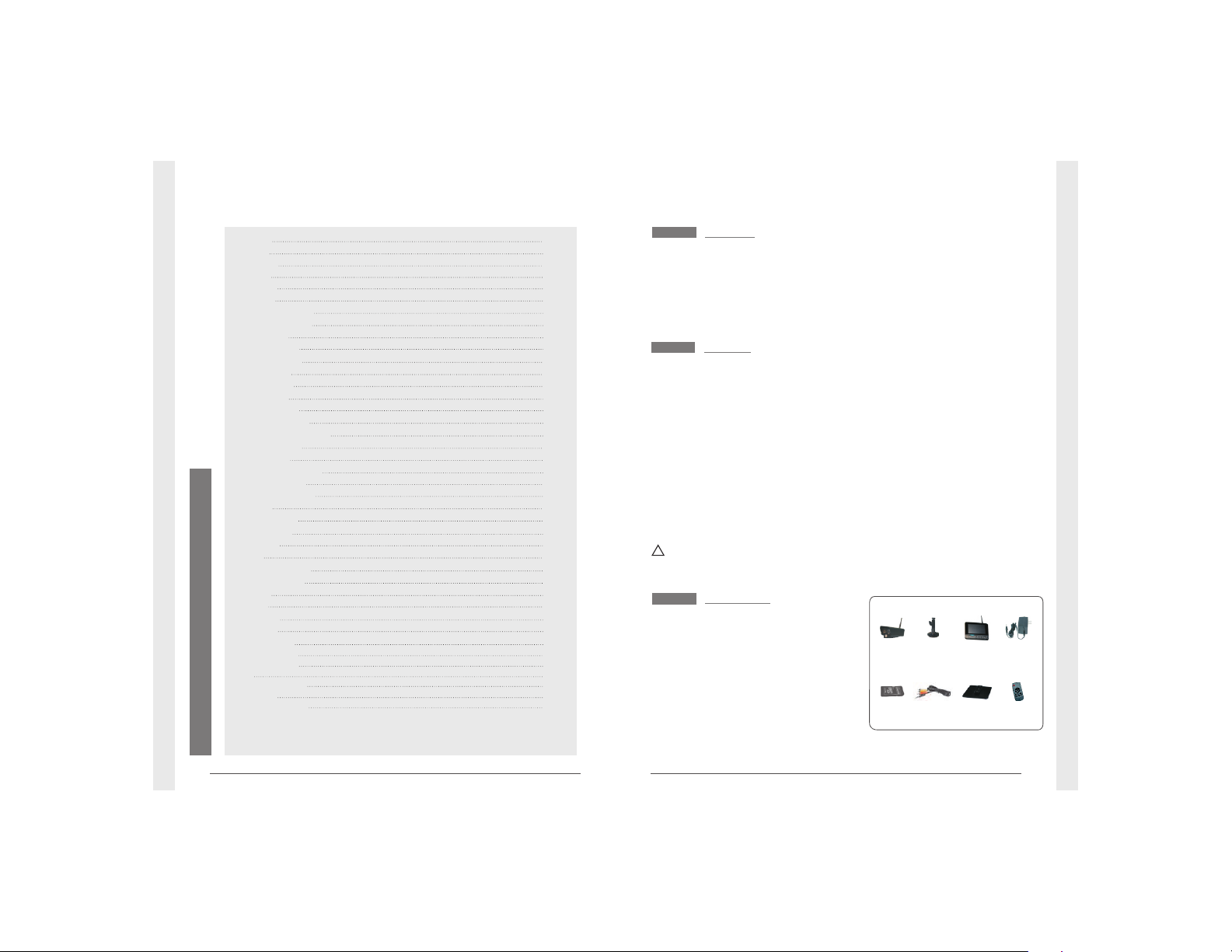
①Camera x 4
②
7"TFT LCD
Monitor
x
1
③
④ Adapter x 5
⑤ SD Card(optional) x 1
⑥ AV Output Cable x 1
⑦ Bracket for Monitor (optional) x 1
⑧ (optional) x 1Remote control
Packing List
Welcome
This product is a household monitoring recording device. It consists
of four cameras installed at entrances/exits of the home and one
DVR receiver with a 7-inch LCD monitor. The four-split screen of
the receiver can display the monitoring pictures of four accessed
cameras. In addition, the infrared sensing alarm function of human
body is available. Thus, a household closed monitoring system is
presented.
* The pictures are for reference only, please refer to real subjects.
For 8105JM, the camera has IR-cut function and image
effect is better than 8104JM.
Bracket for
Camera x 1
⑦ ⑧
① ③②
⑤⑥
④
Features
● 4CH digital wireless camera & DVR system;
● Simple installation- no cables required;
● Total digital wireless, no interferences, no privacy leak;
● 7” LCD monitor with integrated video recorder;
● Support up to 32GB SD card or external mobile disk by USB2.0
(up to 1TBmobile disk);
● Support 4 cameras/ 24hours /7days non-stop overwrite
recording;
● Multiple recording modes: manual,schedule, and motion activated;
● 5m night vision range;
● Video quality: 4CH VGA 10fps, 1CH VGA 30fps;
● Weather proof outdoor cameras with 300m/1000ft transmission
open range;
● Video output function for bigger monitor.
● IR-cut function. (only for 8105JM)
!
Please know that this monitor is not a PC, so some of the memory
devices may not work on this monitor.
Welcome
Features
Packing List
Structure
Installation
Operations
● Basic operations
● Video recording
● Playback
● Delete Video
● Video Output
System setting
● Date / time
● Language
● Record Mode
● Format SD/USB
● Storage for Recording
● Display Items
● TV System
● System Information
● Scan Mode Period
● Mute
● Load Default
● Brightness
● Volume
Record
● Timer Recording
● PIR Recording
Playback
Camera
● Pairing
● Active
● PIP Setting
Alarm setting
Specifications
FAQ
FCC Information
Warnings
02
02
02
03
04
05
05
07
08
09
09
10
11
11
11
12
12
12
13
13
13
14
14
14
14
15
15
15
16
16
16
18
18
19
21
20
21
21
● System Update
13
Troubleshooting
22
Page 3
Structure
03
04
Installation
1. Install the camera at the proper monitoring location. The camera
can be installed in two modes:
3. Insert the SD card or connect an external storage device, such
as a mobile hard disk.
Note: It doesn’t support hot plugging of SD card or external storage
device.
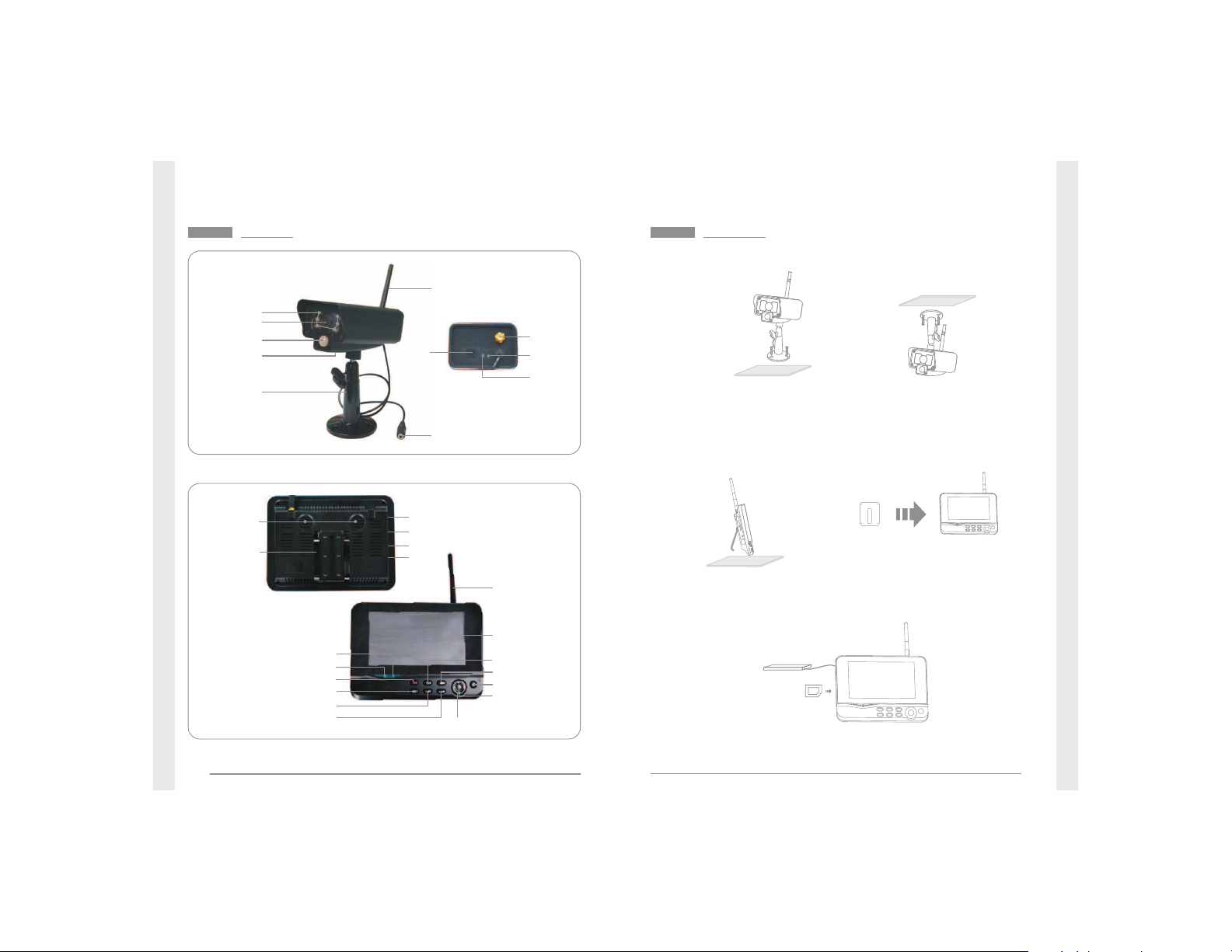
Antenna
7"TFT-LCD
Power on/off
OK Button
Navigate Button
Delete file/LCD、TV Switch
Menu
Record/stop Video
Playback Video
Quarter Display Button
Display Mode
Microphone
Bracket
USB Port
SD Card Slot
AV Output
Power
Port
Link Indicator
Power Indicator
Antenna
Power Input
Infrared LEDs
Lens
Bracket
Antenna
Socket
Link
Indicator
Power
Indicator
Pair
Button
Microphone
① Upright installation:
Install the camera
on a level plane.
② Reverse installation:
Install the camera in
the celilng.
2. Install the receiver at a proper location. This receiver is provided
with two kinds of brackets, so it can be installed in two modes:
① Positioned on a level plane② Mounted to the wall
Use screws to
fix the bracket
to the wall.
Clamp the
receiver on
the bracket
PIR infrared
sensor
Page 4
Operations
05
06
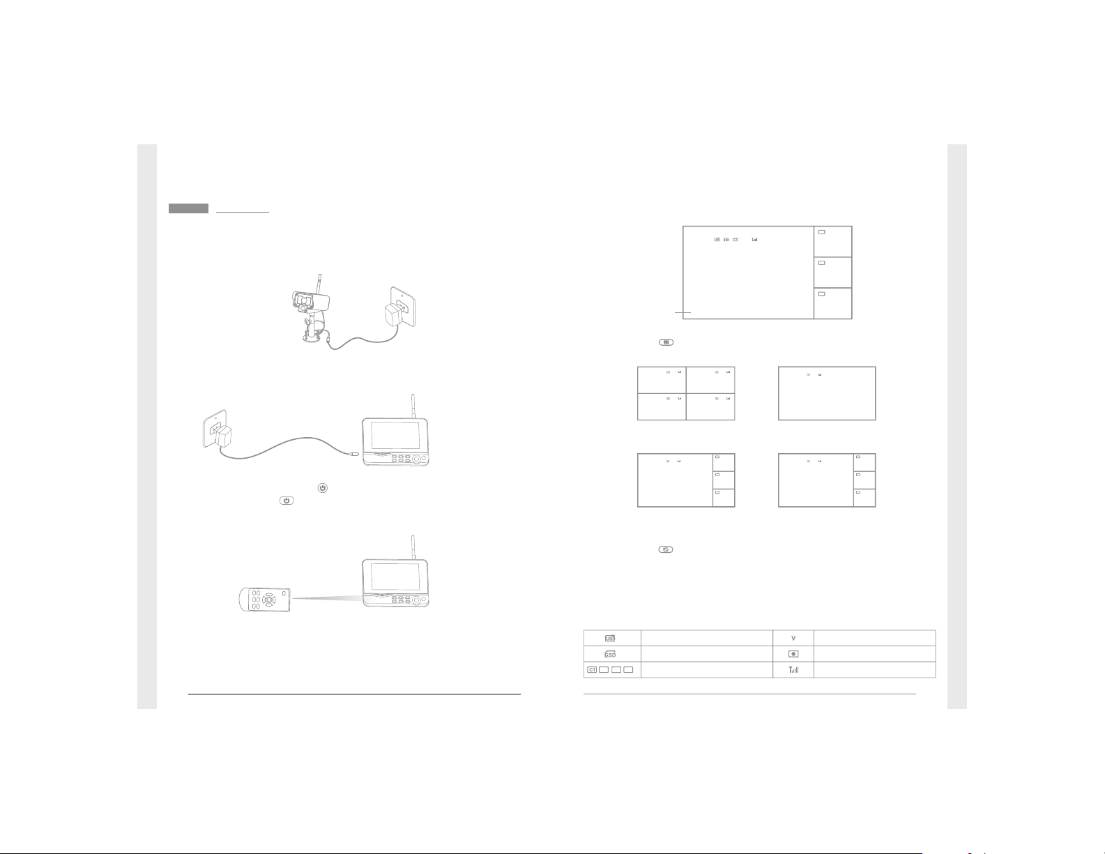
● Basic operations
1. Connect the camera to the power supply. The power Indicator
on the back is turned on:
3. Press the power switch on the receiver for 2s. or press
the power switch on the remote control(direct the remote
control toward the receiver).
The power indicator is turned on and the power-on picture
appears.
4. Pair the cameras and receiver respectively (at most four cameras
can be connected at the same time). Pairing is completed by
default before delivery. If pairing is not completed, complete
pairing according to “Pairing” on page 16.
2. Connect the receiver to the power supply.
6. Press the button to switch between four display modes:
V
2011/11/05/09:30
V
2011/11/05/09:30
C2
C3
C4
2011/11/05/09:30
2011/11/05/09:30
2011/11/05/09:30
V
2011/11/05/09:30
C2
C3
C4
2011/11/05/09:30
2011/11/05/09:30
2011/11/05/09:30
图像显示区域
图像显示区域
图像显示区域
Four picturesOne picture
One large picture and
three small pictures
One large picture and
three small picture
7. Press the button to enter cyclic mode display. Five cyclic
intervals are available: 5s, 10s, 15s, 20s, and 30s and can
be set under “System”.
Meanings of icons on the real-time monitoring picture:
Mobile hard disk inserted
successfully
SD card inserted successfully
Camera name
Signal intensity
Recording status
Current camera
C2
C3
C4
V
2011/11/05/09:30
2011/11/05/09:30
2011/11/05/09:302011/11/05/09:30
5. After successful pairing, the following real-time monitoring
picture appears:
V
2011/11/05/09:30
C2
C3
C4
2011/11/05/09:30
2011/11/05/09:30
2011/11/05/09:30
Picture display area
Time stamp
Picture display area
Picture display area
Picture display area
Picture display areaPicture display area
Picture display areaPicture display area
Picture display area
Picture display area
Picture display area
Picture display area
Picture display area
Picture display area
Page 5

07
08
Manual Recording:
1. In the real-time monitoring status, press the and buttons
to select the camera for video recording as the current camera.
2. Press the recording/stopping button on the device.
The recording icon is displayed on the screen, indicating that
recording starts.
3. Press the button on the device again to stop recording.
Timer Recording:
Set the recording start/stop time through the “Timer Recording”
menu. The device automatically records according to the set
start/stop time. After recording, it automatically saves the video.
Specific steps are as follows:
1. Press the MENU button to enter setting interface;
2. Press the or button to select “Record” and press the OK
button to enter;
3. Press the or button to select “Timer Recording” and press
the OK button to enter;
4. Press the or button to select “New Schedule” and press the
OK button to enter:
● Video recording
1. In the real-time status, press the button to enter playback
interface;
2. Press the or button to select the folder;
3. Press the OK button confirm and enter:
● Playback
/mnt/usb/rec/20121107 2/5
.. (up) <DIR>
065304-1.avi
5MB
065320-2.avi
7MB new
065354-2.avi 5MB new
065417-4.avi 10MB new
'Enter':Play 'Del':Delete
Timer Recording
OK:Options MENU:Quit
Press the or button to select;
Press the or button to adjust;
Press the OK button to confirm and exit;
Camera
End Time
Date
Start Time
All Cameras
11/6/2012 Tue
:
00:00
0000
5. After setting, the device automatically records according to the
set start/stop time.
6. If you press the recording/stopping button on the device
during the recording process, recording stops.
Remarks:
1. If the video recording time is longer than 5 minutes, a video file
will be automatically saved every 5 minutes.
2. Multiple channels (four channels at most) of recording are
supported at the same time. The recorded video of each channel
is saved in an independent video file.
Not browsed
File size
Camera 1
Camera
2
Camera
4
PIR Recording:
If there is human motion detected by any accessed camera, recording
can be triggered. The specific steps are as follows:
1. Press the MENU button to enter the setting interface;
2. Press the or button to select “Record”, press the OK button
to enter;
3. Press the or button to select “PIR Recording”, press the OK
button to enter;
4. Press the or button to select the camera;
5. Press the or button to select “On”;
6. Press the OK button to confirm and exit.
* When “Off” is set, motion detection function is turned off.
* The infrared sensing distance of PIR is 5 m. If the distance exceeds
5m, sensing may fail.
Page 6

09
10
4. Press the or button to select video;
5. Press the OK button to playback:
1. In the video playback mode, press the and buttons to select
the video or video folder to be deleted.
2. Press the button on the device to delete it.
Remarks:
Only the empty folder can be deleted.
● Delete Video
Press the / button to go
backward/forward fast;
press the OK button again
to pause; press the MENU
button to quit the play mode.
In the real-time status, press the MENU button to enter the
following interface:
Press the or button to select “system” and then press the OK
button to enter the system setting interface:
System
Date / Time
Language
Record Mode
Format SD/USB
OK:Options MENU:Quit
System Setting
Date / Time
Language
Record Mode
Format SD/USB
Storage for Recording
Display Items
TV System
System Information
Scan Mode Period
Mute
Load Default
Record Date/Time
Brightness
Volume
Sets the system time and date.
Sets the system language.
Sets to stop recording or overwrite the earliest video record when the
storage medium is full.
Sets whether to format the storage medium.
Sets the storage medium.
Sets whether to display RSSI, Time, SD/USB Status and Camera on the
screen and the recorded video.
Selects a system.
Views the system information.
Sets the cyclic display interval of monitoring picture on the camera.
Turns on/off the speaker on the receiver.
Sets whether to restore default settings.
Sets whether to display the current recording time and date on the recorded video.
Adjusts brightness of the LCD screen.
Adjusts the sound.
You can connect the receiver to a larger monitor/TV to monitor
video more clearly.
● Video Output
Press the button to switch display between the monitor/TV and
the receiver.
2011/11/05/09:30
C2
C3
C4
2011/11/05/09:30
2011/11/05/09:30
2011/11/05/09:30
Picture display area
V
Picture display area
Picture display area
Picture display area
Video Cable
Page 7

11
12
● Date / time
Press the OK button to enter:
Date / Time
OK:Options MENU:Quit
Date
//
2011
11
05
Time
:
23
11
Press the or button to select;
Press the or button to adjust;
Press the OK button to confirm;
Press the MENU button to exit.
● Record Mode
1. Press the OK button to enter;
2. Press the or button to select “Normal” or “Overwrite” and
then press the OK buton to confirm and exit.
Remarks:
Normal: When the SD card or the mobile hard disk is full, the
system stops recording automatically.
Overwrite: When the SD card or the mobile hard disk is full, the
system automatically deletes the earliest videos and
reserves a sufficient storage space to guarantee this
recording.
●
Format SD/USB
1. Press the OK button to enter;
2. Press the or button to select “Cancel”, “SD Card” or “USB Device”;
Cancel: Cancels formatting.
SD Card: Formats the SD card.
USB Device: Formats the USB device.
3. Press the OK button to format:
● Language
1. Press the OK button to enter;
2. Press the or button to select language and then press the
OK button to confirm and exit.
Format SD/USB
OK:Options MENU:Quit
Formatting
, please wait.....
4. After formatting, the system prompts “Format Successfully”,
indicating that formatting succeeds.
●
Display Items
1. Press the OK button to enter;
2. Press the or button to select;
3. Click the OK button to confirm whether to display this item.
If this item is displayed, the icon appears behind this item.
RSSI: Signal intensity icon, icon :
SD USB status: Whether the SD card or mobile hard disk is
inserted, icons :
Camera: Camera name, icons :
4. After setting, press the MENU button to confirm and exit.
C2
C3
C4
● Storage for Recording
1. Press the OK button to enter;
2. Press the or button to select “SD Card” or “USB Device”;
3. Press the OK button to confirm and exit.
Press the or and buttons to select an option, and then press
the OK button to confirm.
Page 8

13
14
● TV System
1. Press the OK button to enter;
2. Press the or button to select;
3. Press OK button to confirm and exit.
●
System Information
1. Press OK button to enter and view;
2. Press the MENU button to exit.
● Mute
1. Press the OK button to enter;
2. Press the or button to select “On” or “Off”;
3. Press the OK button again to confirm and exit.
● Load Default
1. Press the OK button to enter;
2. Press the or button to select “Cancel” or “OK”;
Cancel: Cancels restoration of default settings.
OK: Restores default settings.
3. Press the OK button to confirm and exit.
● Volume
1. Press the OK button to enter;
2. Press the or button to adjust;
3. Press the OK button to confirm and exit.
●
Brightness
1. Press the OK button to enter;
2. Press the or button to adjust;
3. Press the OK button to confirm and exit.
● Scan Mode Period
1. Press the OK button to enter;
2. Press the or button to select;
3. Press OK button again to confirm and exit.
● System Update
1. Press the OK button to enter;
2. Press the or button to select;
3. Press OK button again to adjust;
4. Press button to confirm and exit.
Page 9

15
16
1. In the real-time status, press the MENU button to enter the
following interface:
2. Press the or button to select “Record”;
3. Press the OK button to enter:
Record
Record
OK:Options MENU:Quit
Timer Recording
PIR Recording
● Timer Recording
Set the recording start/stop time. The device automatically records
according to the set start/stop time. After recording, it automatically
saves the video record. For specific steps, see Page 07.
● PIR Recording
If there is human motion detected by any accessed camera,
recording can be triggered. For specific steps, see Page 08.
For specific steps, see Page 08.
Playback
1. In the real-time status, press the MENU button to enter the
following interface:
2. Press the or button to select “Camera”;
3. Press the OK button to enter:
Camera
Camera
OK:Options MENU:Quit
Pairing
Active
PIP Setting
● Pairing
After pairing, the camera is not affected by interference of other
frequencies.
1. Press the or button to select “Pairing”, press the OK button
to enter:
Pairing
OK:Options MENU:Quit
Camera-1
Paired
0xe01f0008
Camera-2Paired0xe01f0007
Camera-3Paired0xe01f0006
Camera-4Paired0xe01f0005
Page 10

17
18
2. Press the or button to select camera;
3. Press the OK button to pair:
Pairing
OK:Options MENU:Quit
Camera-1
Paired
0xe01f0008
Camera-2Paired0xe01f0007
Camera-3Paired0xe01f0006
Camera-4Paired0xe01f0005
Pairing.....
Long press the PAIR button on TX for 2 seconds
52
4. Within 60s, press the Pairing button on the back of the camera
for 2s.
5. After successful pairing, the receiver screen displays the following
information:
Pairing OK
Congratulations!!!
Remarks:
If pairing fails, the system prompts “Pairing failed”. Please
perform pairing again.
● Active
1. Press the or button to select “Active”, press the OK button
to enter:
Active
OK:Options MENU:Quit
Camera-1
Off
Paired
Paired
Paired
Camera-2
Camera
-4
Camera
-3
On
On
On
2. Press the or button to select the camera;
3. Press the or button to select “On” or “Off”;
4. Press the OK button to confirm and exit.
Special not e: When “OFF” is set, the camera does not have any
action, such as monitoring picture display, recording, or automatic
alarm.
●
PIP Setting
Set the resolution and pixels for the recorded video.
1. Press the or button to select “PIP Setting”, press the OK
button to enter:
PIP Setting
OK:Options MENU:Quit
2. Press the or button to select the camera;
3. Press the OK button to enter the following interface:
Camera-1LowHigh
Camera-2High
Camera-3High
Camera-4HighHigh
High
High
Page 11

19
20
Base/PIP Setting
OK:Options MENU:Quit
Resolution Size
Quality
High
Low
Top
High
Medium
Low
Press the or button to select “Resolution Size” or “Quality”;
Press the or button to select “Top”, “High”, “Medium” or “Low”;
Press the OK button to adjust;
Press the MENU button to confirm and exit.
Here, you can set whether to send an alarm automatically when
any motion detected by the camera:
1. In the real-time status, press the “MENU” button to enter setting
interface;
2. Press the or button to select “Alarm”;
3. Press the OK button to enter;
4. Press the or button to select “On” or “Off”;
5. Press the OK button to confirm and exit.
Alarm Setting
Specifications
* All the specifications are subject to minor change without prior notice.
Video Resolution
Viewing Angle
Video Format
SD Card
Items
Imaging Sensor
Monitor
Power Supply
656 x 488
70°
8104JM
1/-inch5 color CMOS
.AVI
5V
Supports to 32GB
Consumption Current (Max.)
400mA
Dimensions( W x DH ) x
Operating Humidity
Operating Temperature
Approx. Weight
214 (mm)x 157x 26
492g
15~85%RH
-10℃~50℃
USB 2.0
Date Output
Hard Disk
Supports to 1TB
LCD Screen Type
7"TFT LCD
LCD Screen Resolution
800*480
Video Frame Rate
30fps max
.()
CIF/VGA
Video Resolution
Dimensions( W x DH ) x
Approx. Weight
131 (mm) (exclude the bracket)x 63x 58
282g
Power Supply
5V
Camera
IP54
Waterproof Capacity
Unobstructed Effective Range
Night Vision Distance
200m (Min.)
5m (Max.)
Consumption Current (Max.)
700mA
Unobstructed Effective Range
200m (Min.)
Page 12

21
22
Warnings
● This product shall not be exposed to water either by dripping,
splashing, immersing, etc., unless otherwise indicated.
● Turn off the system if it is not in use.
● This product can only be completely disconnected for from its
power source by unplugging the power adapter.
● Do not cut the DC power cable of provided with this product
to fit with another power source.
FCC Information
This device complies with part 15 of the FCC Rules. Operation is
subject to the following two conditions:
(1) This device may not cause harmful interference;
(2) This device must accept any interference received, including
interference that may cause undesired operation. Changes or
modifications not expressly approved by the party responsible
for compliance could void the user’s authority to operate the
equipment.
FAQ
1. Why does not the screen display any monitoring picture after
the camera is connected?
Answer: 1. Please check whether “Active” is set to “ON”.
2. Please check whether pairing succeeds.
2. The recording time is set already or the human body sensing
recording is enabled, but the receiver does not start recording
when the time comes or a human body is sensed. Why?
Answer: 1. Check whether the storage medium is inserted.
2. Check whether the storage medium is full.
3. The system does not respond when the playback button is
pressed. Why?
Answer: Please check whether the current camera is in the recording
status. If it is in the recording status, the system will not
respond when this button is pressed.
Page 13

IMPORTANT NOTE:
FCC Radiation Exposure Statement:
This equipment complies with FCC radiation exposure limits set forth for an
uncontrolled environment .This equipment should be installed and operated with
minimum distance 20cm between the radiator& your body.
This transmitter must not be co-located or operating in conjunction with any other antenna or
transmitter.
 Loading...