

Page 1
Made in China
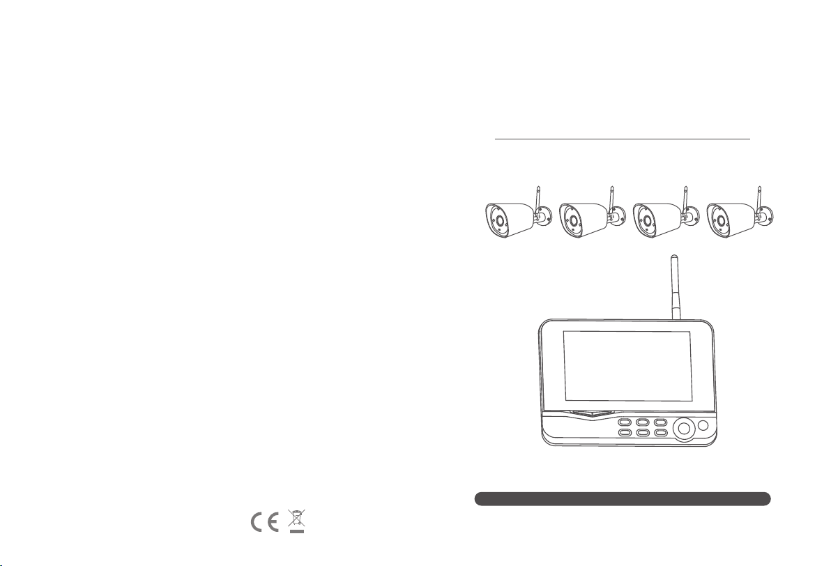
Four-Channel Wireless Digital
Surveillance System
Model 8005BU:
Thank you for your purchasing of our product. Please read the instructions
carefully before use of the produc
Version: 1.0
Page 2
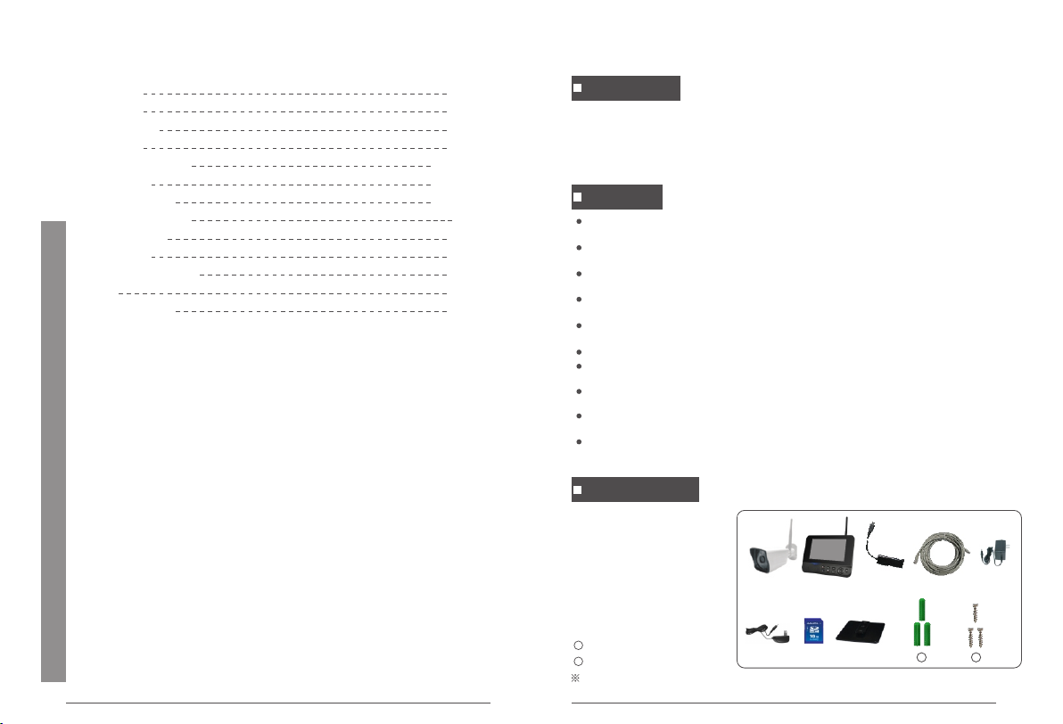
Table of Contents
Overview
Features
Packing List
Structure
Install and Connect
Operations
System Settings
Recording Settings
Alarm Settings
Attentions
Technical Parameters
FAQ
Troubleshooting
01
04-05
06-12
13-17
02
02
02
03
Overview
This product is a home surveillance video recording device. It consists of a camera
installed in each of the home's entrances and exits and a receiver with its own 7-inch
LCD display. The receiver can simultaneously access the monitoring images of 4 cameras
at the same time. It has a human detection function, thus forming a set of home closed
monitoring system.
Features
17
18
18
19
20
21
The fou r-chan ne l wirel es s camer a recor di ng syst em reco rds 108 0P real -t ime
video s on a ll chan ne ls, cle arer th an t raditio nal DVR;
Each FH D ca mera ca pt ure s in credi bl y clear images record s eve ry det ai l day and
night ;
Playb ack of im port ant evi de nce or in te res ti ng vide os o n four ch an nels al lo ws
you to kn ow actu al d evelo pm ent of th e entir e event ;
No wiri ng , easy in st allat io n, auto ma tic pai ring, p lu g and pla y, up t o 20m nig ht
visib il ity;
Suppo rt 4T1 R for bar ri er-f re e trans mi ssion o f 400 met er s in open s pace, a nd
suppo rt ext ernal 1 28 G SD card f or vide o st orage ;
Suppo rt rem ote v ie wing on IOS /A ndroi d app and C MS c omput er c lient ;
A var ie ty of r ecord ing modes a re avai lable : ma nual re cordi ng , sched ul ed
rec ordin g an d motion de tecti on record ing;
24/7 lo op reco rding by fo ur-cha nn el 1920 *1 080P fu ll H D camer as , with ra in
pro te ction ( IP 55);
The rec eiver c om es with a 7 -i nch mat te LC D, allowin g for 1024* 600 displ ay,
camer a resol ut ion 192 0* 1080P ;
Sof tw are upd at e for rec eiver a nd c amera t hroug h a SD c ard ins er te d into th e
rec ei ver
Packing List
① Camera x (1~4)
② 7-inch LCD monitor x 1
③ Micro USB to RJ45 adapter x 1
④ Network cable x 1
⑤ Camera power adapter x (1~4)
⑥ Receiver power adapter x1
⑦ SD card (optional) x 1
⑧ Monitor bracket (optional) x 1
9
Anchor x 7-16
10
Screw x 7-16
Pictures in the manual are for reference only. Please refer to the actual product.
⑥
⑦ ⑧
③
②①
④ ⑤
9 10
02
Page 3
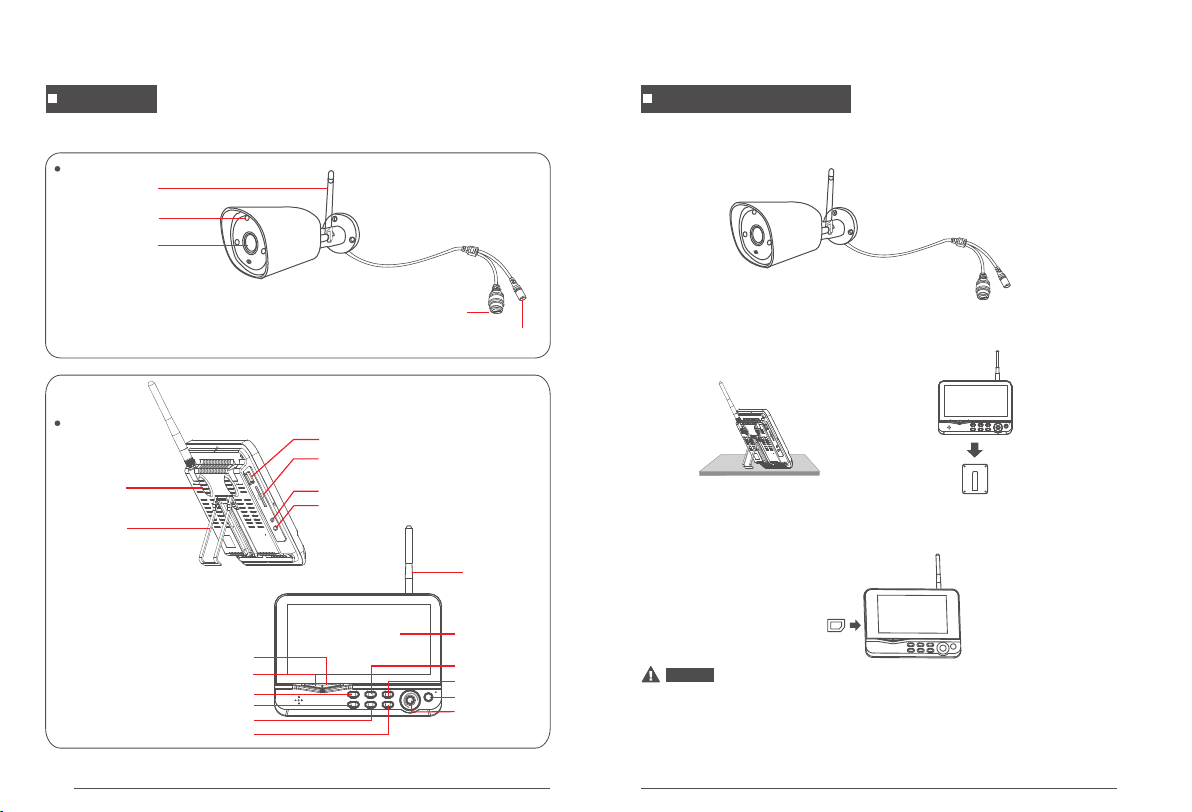
Structure
Camera
Antenna
IR Light
Receiver
Speaker
Bracket
Lens
USB Port
SD Card Slot
MicroUSB
Power Interface
RJ45
DC12V
Install and Connect
1. Install the cameras in place for ideal monitoring and fasten with screws.
2. Install the receiver in place. The receiver comes with two types of brackets, so there are
two ways to install it:
Fasten the bracket to
the wall with screws
and slide the receiver
to snap onto the bracket.
① Stand it on a flat surface ② Mount it to wall
(optional)
Antenna
7-inch LCD
Power Indicator
Pairing Indicator
Manual Recording Button
Images Display Switch Button
File Delete Button
Menu
Scan
Playback Button
ON/OFF button
OK button
03
3. Insert the SD card.
Notice
※ The SD card or external storage device does not allow hot swapping.
※ Maximum storage capacity is up to 128GB.
※ If the SD card to be used in this unit has already been used, format it first before use.
※ Please use an SD card with a card speed class of 4 or higher. Otherwise, it cannot be
recognized.
04
Page 4
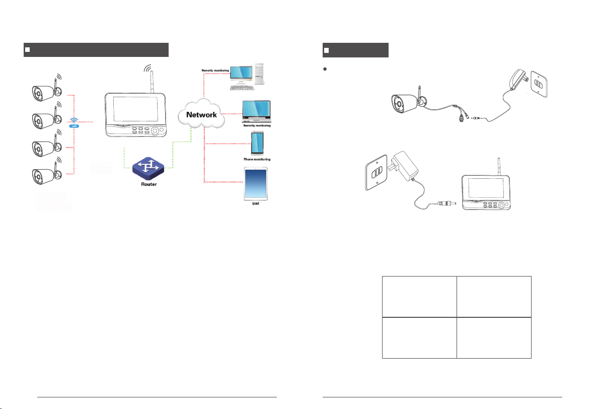
Wireless Connection
This me th od is use d fo r Wirel ess con ne ction. Af te r conne ct ion, it c an b e
opera ted on a Wi re less or m ob ile pho ne .
Notes:
1. In the effective range of wireless connection, the cameras can be connected to the
receiver. If the distance is too far or there is an obstacle, wired
connection is required.
2. The receiver cannot be connected to the router wirelessly. A network cable is required
for their connection.
Operations
Basic Operations
1. Connect the camera to mains.
2. Connect the receiver to mains.
3. After Poweron, the cameras and receiver will automatically start up, and then
real-time monitoring screen appears as follows:
2013/11/15/09:30
Image display area
2013/11/15/09:30
1 2
Image display area
2013/11/15/09:30 2013/11/15/09:30
Image display area Image display area
Note: The receiver can only connect up to 4 cameras; pairing has been completed by
default at the factory. If they have not been paired, please complete pairing
according to the description of “Pairing” on page 15.
05
3 4
06
Page 5

CMS Client Download
1. Open t he b row se r on PC and e nt er http :/ /www.g os cam.c om i n the add re ss ba r
to vi si t the off icial web site of G OSCAM .
2. Go to "S er vi ce s and Sup po rt " -> "Dow nl oad Cen ter" -> " Ho me Secu ri ty " ->
"NVR" , do wnloa d the "CM S Se tup" an d in stall i t to y our PC.
Mobile APP Download
You can use you r mobile phone to sc an the QR codes belo w, or search “Go see vie w”
in App Store or Google Play to do wnl oad an d Inst all the APP. Then, run the AP P and
take a fe w minut es to reg ister a n ac count .
CMS Client Operations
Login : Do uble- cl ick on th e CM S app ico n on t he
deskt op to tur n on the app an d log in to t he s ystem ;
Initi al I D is “adm in ” and the re is no pa ss word.
Add Device:(Select 1 of the 3 methods)
1. Aft er log in, cl ick “D evi ce Man agem ent ” at the bo ttom of the scr een . Conn ect LA N Cabl e,
the s ys tem wil l au tom at ica ll y sea rc h for d ev ice s. Ti ck the ca me ra to b e ad ded b y ad din g
a mark “ ” in t he “ ” and cl ic k “Ad d” .
2. Afte r lo gin, cl ic k “Add ” in the up pe r right c or ner of th e scree n to brin g up a
dialo g box (as s ho wn belo w) . Selec t “I P/DDNS”, e nter th e IP a ddres s of the
rec ei ver in th e IP /DDNS f ie ld (the I P ad dre ss of the rec eiver c an b e acqui red in th e
Goseeview
07
“Sy stem Se tt ings” — Wi red Net wo rk ") and s el ect "NV R" i n the Type f ie ld. The n,
click “ Fi nish”.
08
Page 6

Note: 1 . Th e IP addr ess of th e rec ei ver is va lid onl y wh en it con ne cted to t he
netwo rk and open a utoma ti c acces s is o pened .
2. If the a dd ing fai ls , tr y repla ci ng the port num be r, whi ch i s optio na l
for"8 0、 10000 ".
3. Afte r lo gin, cl ic k “Add ” in the up pe r right c or ner of th e scree n to brin g up a
dialo g box (as s ho wn belo w) . Selec t “C loud ID”, an d en ter t he I D number of the
rec ei ver in th e Co uld ID fi el d (the ID n um ber of th e recei ver is th e la st 10 dig it s
found i n “Syst em Sett in gs—Sy stem In fo rmati on ” - "UID" ). T hen, cl ic k “Fini sh ”.
Note: I n th e three m ethod s as d escri be d above f or d evice a dd ing, af te r th e devic e
is adde d, y ou need t o retur n to the “D ev ice Lis t” i n the upp er r ight co rn er of t he
home pa ge to dou bl e-cli ck o r right- cl ick “Co nn ect Vid eo”.
Delete Device:
1. Afte r lo gin, cl ic k “Device M an ageme nt ” at the bo ttom of t he scre en , and
selec t th e devic e yo u want to d elete i n th e upper r ig ht of t he s cre en . Then,
click “ De lete” o n the right a nd c lick “O K” i n the pop -u p dialo g.
Mobile APP Operations
Add Device:(Select 1 of the 2 methods)
1. Afte r re gistr at ion, ch ec k the “De vi ce Conn ec ted to In terne t” o n the scr een,
and ent er the ID num be r of th e recei ve r in the “C lo ud ID” fi el d (the ID n um ber
of th e recei ve r is last 1 0 di gits fo un d in “Sys tem Set tings—Syst em I nform at ion”
- "UID" ). T hen, cl ic k "Save" .
Note: I D: “ admin" , Pas sw ord : “N ull”.
09
10
Page 7

2. Afte r re gistr at ion and l og in, cli ck “ LA N Sc an” on th e sc ree n. I n the LA N state ,
the sys tem will au tomat ic ally se ar ch for th e de vice. O nc e a searc h res ul t appears ,
click t he d evice y ou w ant to ad d.
Delete Device:
1. Afte r lo gin, se le ct the devi ce you wa nt t o delet e an d click “ ” i n th e upper
right o f the scr een. Th en , click “ De lete”.
11
Receiver Operations
Manual Recording:
1. In the real-time monitoring state, press the “ ” or “ ” button to select the
camera that needs to record video as the current camera;
2. Press the “Recording/Stop Recording” button on the device, and an icon
appears on the display to indicate that video recording starts.
3. Press the button again to stop recording.
Note: W he n the vid eo f ile rea ches 8M B in s ize, th e sy stem au to matic al ly pa ck s a
file. T he s ystem i s ab le to c on duct mu lt i-cha nn el reco rding s im ultan eo usly (up
to 4 ch an nels) , an d the video s recor ded on ea ch c hanne l ar e saved i n a separ ate
video f ol der.
Scheduled Recording:
As the user sets start and end time in the “Record Setup” menu, the device will
automatically conduct video recording according to the set time and type. The specific
steps are as follows:
1. Press MENU on the device to enter the menu interface;
2. Press the “ ” or “ ” button to select “Recording Settings” and press OK to enter the
interface;
3. Select “Record Setup” and press OK to enter the interface;
4. Press the “ ” or “ ” button to select “Schedule 1-4”, press OK to enter, and
set the start and end time:
Enable
Channel
Weekday
Type
Time 00 : 00 ~ 23 : 59
OK : Select MENU : Back
5. After setting of various items, the device will automatically conduct video recording
according to the set start and end time and type.
Video Playback:
1. In the real-time monitoring state, press the playback button on the device to
enter the video playback interface;
2. Press the “ ” or “ ” button on the device to select (Channel-Date-Time period)
the video to be played back, and press OK to play;
3. Press the “ ” or “ ” button to play fast backward and fast forward, press
the “ ” or “ ” button to adjust the volume, and press OK again to pause;
4. Press MENU to exit the playback mode.
Record Setup
1.2.3.4
Motion,Timer
Press the “ ” or “ ” button to
select the setting item;
Press the “ ” or “ ” button to
set;
Press OK button to confirm and exit.
12
Page 8

Motion Detection Recording:
When an object moves within the angle of view of any one of the cameras connected,
the device can be triggered for recording. The specific steps are as follows:
1. Press MENU on the device to enter the settings interface.
2. Press the “ ” or “ ” button to select “Alarm Settings” and press OK to enter;
3. Press the “ ” or “ ” button to select the channel to be set in “Channel 1-4”,
and press OK to enter;
4. Press the “ ” or “ ” button to select “Motion” and press OK to turn it on (this
function is enabled by default);
5. Press the “ ” or “ ” button to select “Mobile APP Alarm” and press OK to
turn it on (this function is valid only when the device is connected to the internet and
the device has been added in the mobile APP);
6. Press the “ ” or “ ” button to select “Alarm” and press OK to turn it on (this
function is enabled by default);
7. Press MENU to go back when the steps have been finished.
System
Settings Items
Language
Time Setup
Wired network
Match Code
Wireless hotspot
System info
Upgrade
Factory settings
Volume
IPC upgrade
Functions
Set system language;
Set system time and date;
Turn on or off "Automatically"; enter network parameters manually; suggest to
turn on " Automatically" to get the network parameters.
Add/remove camera;
The wireless SSID and password for point-to-point connection between the camera
and receiver cannot be set; appropriate regional frequency band can be selected
according to different regions;
View system information;
Receiver system upgrade;
Whether or not to restore default settings;
Adjust the volume;
Camera upgrade;
System Settings
1. In the real-time monitoring state, press the “MENU” button on the device to enter
the main menu interface;
2. Press the “ ” or “ ” button to select “System Settings”, and press OK to enter
the system settings interface;
3. Press the “ ” or “ ” button to select an item and press OK to enter the
corresponding settings interface.
Mai n Menu
OK : Select MENU : Back
Main Me nu I nterfac e Sys tem Set ti ngs Int er fa ce
13
Language
Time Setup
Wired Network
Sensor S etupVideo Pl aybac k System Se tup Record Se tup
Match Code
OK : Select MENU : Back
System Setup
Language Settings
1. Press MENU on the device to enter the menu interface;
2. Press OK to enter the language settings interface;
3. Press the “ ” or “ ” button to select an appropriate language, and press OK to
confirm and exit.
Time Settings
1. Press MENU on the device to enter the menu interface;
2. Press OK to enter the time settings interface;
3. If the device has been connected to the Internet, enable the “Time Sync” function;
4. You can also make manual settings. Press the “ ” or “ ” button to select “Time
Settings” option and press OK to enter the time settings interface.
System Setup
/ /
09
Date
Time
11
:
15
30
2018
OK : Select MENU : Back
Press the “ ” or “ ” button to
select the change item;
Press OK to confirm;
Press the “ ” or “ ” button to
change;
Press MENU button to exit the time and
date settings interface.
14
Page 9

Wired Network Settings
1. Press MENU on the device to enter the menu interface;
2. Press OK to enter the wired network settings interface.
3. Select “Obtain an IP address automatically” and press OK to turn it on. Then, the
device will automatically obtain a network IP address; or the IP address can be entered
manually.
Add by Pairing Settings
1. After the receiver and camera are powered on, the camera is connected to the
receiver by a network cable;
2. Press MENU on the device to enter the menu interface;
Rec eiver
Netwo rk c able
Camer a
3. Press OK to enter the Match Code Settings interface;
4. After connecting the camera to the receiver by a network cable, press
the “ ” or “ ” button to select “Match Code” and press OK to confirm;
5. Press the “ ” or “ ” button to select the “x” on the right side, and press OK
to delete the paired camera.
6. After a paired camera has been deleted,
if you want to re-pair, just turn on the
camera and keep it within an effective
range of wireless connection, and then
you can complete pairing with no need
of a network cable (if you want to avoid
pairing again, please turn off the camera);
OK : Select MENU : Back
Camera-1
Camera-2
Camera-3
Camera-4
System Setup
Matched
0xe01f0008
Matched
0xe01f0007
Matched
0xe01f0006
Matched
0xe01f0005
Match Code
X
X
X
X
Wireless Hotspot Settings
1. Press MENU on the device to enter the menu interface, and press OK to enter the
wireless hotspot settings interface;
2. Press the “ ” or “ ” button to select the appropriate “Area and Wireless
Channel”, press OK to confirm and exit.
Note: This feature is only used for wireless connections between the “Receiver and Camera”.
System Information Settings
1. Press MENU on the device to enter the menu interface, and press OK to enter the
system information settings interface;
2. Press MENU to exit.
Upgrade Settings(For Monitor)
1. Press MENU on the device to enter the menu interface, and press OK to enter the
upgrade settings interface. Select “Local Upgrade” and press MENU to exit.
Note: The upgrade program needs to be downloaded to the storage device and
upgraded via USB interface or SD card. Online upgrade is not supported.
Factory Settings
Press MENU on the device to enter the menu interface, and press OK to enter the
factory settings interface.
1. Simple restore: ignore channel and network configuration
2. Restore all: restore all configurations
Volume Output Settings
1. Press MENU on the device to enter the menu interface, and press OK to enter the
wireless hotspot settings interface;
2. Press the “ ” or “ ” button to select an appropriate volume (0-4), and press OK
to confirm and exit (in the real-time monitoring state, press the “ ” or “ ” button
to adjust the volume).
Note: The defaulted volume is (2)
IPC Upgrade Settings (For Camera)
1. Press OK to enter the IPC upgrade settings interface.
2. Press the “ ” or “ ” button to select the channel to be upgraded. It is
recommended to enable “Allow Downgrade”.
3. Press the “ ” or “ ” button to select “Start” and press OK to confirm.
Note: The upgrade program needs to be
downloaded to the storage device and
upgraded via USB interface or SD card.
Online upgrade is not supported.
Info
Channel
Source
Allow Downgrade
OK : Select MENU : Back
System Setup
Local Upgrade
Start
1
15
16
Page 10

Recording Settings
1. In the real-time monitoring state, press the “MENU” button on the device to enter
the main menu interface;
2. Press the “ ” or “ ” button to select “Recording Settings” and press OK to
enter the recording settings interface;
3. Press the “ ” or “ ” button to select an item and press OK to enter the settings
interface.
Mai n Menu
Recording Schedule
SD Card Manage
Sensor S etupVideo Pl aybac k System Se tup Record Se tup
OK : Select MENU : Back
Overwrite
OK : Select MENU : Back
Main Me nu I nterfac e Rec ordin g Se tting s In ter face
Recording Schedule Settings
1. Press OK to enter the recording schedule settings interface;
2. Press the “ ” or “ ” button to select the set schedule (1-4), and press OK to
confirm and enter;
3. For details, please refer to “Scheduled Recording” (page 13).
Record Setup
Schedule 1
Schedule 2
Schedule 3
Schedule 4
Enable
Channel
Weekday
Type
Time 00 : 00 ~ 23 : 59
OK : Select MENU : BackOK : Select MENU : Back
SD Card Management Settings
1. Press OK to enter the SD card management settings interface;
2. This function allows you to view the capacity usage of the SD card and “format” the
SD card.
Record Setup
Record Setup
1.2.3.4
Motion,Timer
Alarm Settings
1. In the real-time monitoring state, press the “MENU” button on the device to enter
the main menu interface;
2. Press the “ ” or “ ” button to select “Alarm Settings”, press OK to enter the
alarm setting interface;
3. Press the “ ” or “ ” button to select the channel to be modified (1-4), press OK
to enter the setting interface;
Sensor Setup
Channel 1
Channel 2
Channel 3
Channel 4
OK : Select MENU : Back OK : Select MENU : Back
Motion
Sensitivity
APP Alarm
Alarm
Area Edit
Sensor Setup
Highest
Alarm S et tings M en u Alarm S et tings M en u
4. Select whether to turn on the “Motion, Mobile APP, Alarm (Receiver gives an alarm
sound)” alarm.
Attentions
Do not place the device at a position where it is easy to fall down or in a place where
liquid may easily splash into it.
When not in use, turn off the camera/monitor.
The power of this product can be completely turned off only after the power adapter
has been unplugged.
17
18
Page 11

Technical Parameters
FAQ
Ca mer as
Dimensions (length X width X height)
Mo nit or
Dimensions (length X width X height)
RF C har ac te ris ti cs
Unobstructed transmission distance
Items
Image sensor
Video pixels
Horizontal viewing angle
Night vision distance
IP rating
Interface
Operating voltage
Operating temperature
Operating humidity
Display
Display resolution
SD card capacity
Interfaces
Storage video resolution
Storage format
Data output
Operating Voltage
Operating temperature
Operating humidity
USB 2.0, DC JACK(○3.5mm) MicroUSB, SD card
Parameters
1/2.9",CMOS
1920 x 1080P
°
H:85
20m (Max.)
IP55
DC JACK(○5.5mm) RJ45
DC 12V/1A
-10℃~50℃
15~85%RH
176x47x46(mm) (without bracket)
"
7 TFT LCD
1024 x 600
Up to 128GB
1920 x 1080P
H.265
USB 2.0
DC 5V
0℃~40℃
15~85%RH
214x26x157 (mm)
400m (4T1R)
All parameters are subject to minor changes without prior notice.
1. Q: Why can't the monitoring images be displayed on the screen after the camera is
connected?
A: 1. Please check if the antennas of camera and receiver are installed or configured in
place.
2. Please check if screen display of the receiver is turned on.
3. Please check if pairing is successful.
2. Q: The recording time has been set or the motion detection recording enabled. When
the time arrives or a motion is detected, why is video recording not started?
A: 1. Please check if a storage card has been inserted.
2. Please check if the storage medium works.
3. Hot swapping of storage medium is not supported. So, check if the problem is
caused by hot swapping; if it is, please power off the receiver and then power it
on again.
4. Please check if the storage medium is full. If it is full, the automatic override
function should be enabled. Check if the function is enabled ( in recording setting).
3. Q: When an external HDD is connected via the USB port, why cannot it be recognized?
A: Currently, the device does not support connection of a mobile HDD for storage.
4. Q: When an ID number is entered in the APP to add receiver, adding fails?
A: Please check the format of the ID number you have entered. A correct ID number is
the last 10 digits of the UID number.
5. Q: The alarm volume from the motion detection receiver is too large, how to adjust?
A: In the real-time preview interface, click the “Up” and “Down” arrow buttons to
adjust the alarm volume.
19
20
Page 12

Troubleshooting
Problems
LCD does not
display monitoring
images
No videos
Poor image
quality
EU E nv ir on me nt al P ro te ct ion
Wast e elect rical p roduc ts shou ld not be
dis posed o f with ho useho ld wast e. Plea se
rec ycle wh ere fac iliti es exis t. Chec k with
you r local a uthor ity or re taile r for rec yclin g
adv ice.
Please check if the cameras are turned on.
Check if the cameras have been "paired".
Check if the storage medium has been inserted; hot swapping of
storage medium is not supported. So, check if the problem is
caused by hot swapping.
Check if the storage medium is full and if the automatic override
function is enabled.
SD card connection failed; it is recommended to use brand SD
card, such as Kingston, SanDisk, Panasonic, Kingmax, etc.
An external mobile HDD is not supported. Please check if it is an
external HDD that results in no videos.
Check if there is interference, such as WIFI interference or
interference from other wireless devices.
Check if the antennas of the cameras and the monitor are
installed.
Solutions
FCC Cer tification lnfo
Note: T his equip me nt has be en test ed a nd foun d to comply w it h the lim it s for a Cla ss B
digit al d evice , pu rsuan t to par t 15 of t he F CC Ru les. Thes e li mits ar e desig ne d to
pro vi de re as onable pr ote ct ion again st harmfu l in ter ference i n a resid en tial in st allat io n.
This eq ui pment g en erate s, u ses and c an r adiat e radio fre quenc y en erg y an d, if not
insta ll ed and us ed i n accor dance w it h the instr uctions , ma y cause h ar mful in terfere nc e
to ra di o commu ni cations . Howev er, ther e is no gua ra ntee th at i nterfer ence wi ll n ot
occur i n a part icula r in stall at ion. If t hi s equip me nt does c au se harm fu l inter fe rence t o
radio o r televis io n rec ep tion, w hi ch can be d et ermin ed b y turni ng t he equi pm ent off a nd
on, the u se r is enco ur aged to t ry to co rrect t he i nte rf er ence by o ne o r more of the
follo wi ng meas ures:
—Re orien t or r eloca te the re ce iving a ntenna.
—Incr ease th e se parat io n betwe en the equi pm ent and r eceiv er.
—Conn ec t the equ ip ment in to a n outle t on a c irc ui t diffe rent from t hat to wh ich the
rec ei ver is co nn ected .
—Cons ul t the dea le r or an exp er ience d ra dio/T V technic ia n for hel p.
Chang es o r modif ic ation s no t expre ssly appr oved by t he party re sp onsib le f or
compl ia nce cou ld v oid the u se r's a uthor it y to oper ate the e qu ipment.
This de vi ce comp li es with Par t 15 of t he F CC Ru les. Oper at ion is su bj ect to th e
follo wi ng two co nd ition s:
(1)th is d evice m ay n ot caus e ha rmful i nt er feren ce, and ( 2) t his dev ic e must ac ce pt
any int er fe ren ce rece iv ed, inc lu ding in te rf ere nc e that ma y ca use undes ired op er ation .
RF expo su re wa rn ing :
This eq ui pment c om plies w it h FCC r ad iatio n ex posur e limit s se t fort h for an
uncon troll ed envir on ment. T hi s equip me nt shal l be i nstal le d and ope ra ted wit h
minim um d istan ce 2 0cmbe tw een the r ad iator & b ody.
This de vi ce is act in g as slav e an d opera ti ng in the 2 .4 G Hz (241 2 ~2 462 MHz )band .
Ad Hoc fu nc tion is s up ported bu t no t able to o pe rate on n on-US f re quenc ie s.
Do not us e th e devic e wi th the en vi ron me nt which be low minim um - 30 ℃ or
maxim um over 50 ℃ .
Hereb y, we decl ares that t his devic e is i n compl ia nce wit h th e essen ti al re qu ire
ments a nd o ther re levan t provi si ons of Di rec ti ve 2014 /5 3/EU.
Notic e: O bser ve the na ti onal lo ca l reg ul ations in t he locati on w here th e devic e is
to be u se d.
This de vi ce may be r estri ct ed for us e in s ome or al l me mber st at es of t he
Europ ean Uni on ( EU).
21
22
 Loading...