

Page 1
Page 2
Welcome
Features
Packing List
Structure
Installation
Operations
● Basic operations
● Video recording
● Playback
● Delete Video
● Video Output
System setting
● Date / time
● Language
● Record Mode
● Format SD/USB
● Storage for Recording
● Display Items
● TV System
CONTENTS
● System Information
● System Update
● Scan Mode Period
● Mute
● Load Default
● Brightness
● Volume
Record
● Timer Recording
● PIR Recording
Playback
Camera
● Pairing
● Active
● PIP Setting
Alarm setting
Specifications
FAQ
FCC Information
Warnings
Troubleshooting
For 8105JM, the camera has IR-cut function and image
effect is better than 8104JM .
01
02
02
02
03
04
05
05
07
08
09
09
10
12
12
12
13
13
13
13
14
14
14
14
15
15
15
16
16
16
18
18
19
20
21
21
22
11
11
11
21
Welcome
This product is a household monitoring recording device. It consists
of four cameras installed at entrances/exits of the home and one
DVR receiver with a 7-inch LCD monitor. The four-split screen of
the receiver can display the monitoring pictures of four accessed
cameras. In addition, the infrared sensing alarm function of human
body is available. Thus, a household closed monitoring system is
presented.
Features
● 4CH digital wireless camera & DVR system;
● Simple installation- no cables required;
● Total digital wireless, no interferences, no privacy leak;
● 7” LCD monitor with integrated video recorder;
● Support up to 32GB SD card or external mobile disk by USB2.0
(up to 1TBmobile disk);
● Support 4 cameras/ 24hours /7days non-stop overwrite
recording;
● Multiple recording modes: manual,schedule, and motion activated;
● 5m night vision range;
● Video quality: 4CH VGA 10fps, 1CH VGA 30fps;
● Weather proof outdoor cameras with 300m/1000ft transmission
open range;
● Video output function for bigger monitor.
● IR-cut function. (only for 8105JM)
!
Please know that this monitor is not a PC, so some of the memory
devices may not work on this monitor.
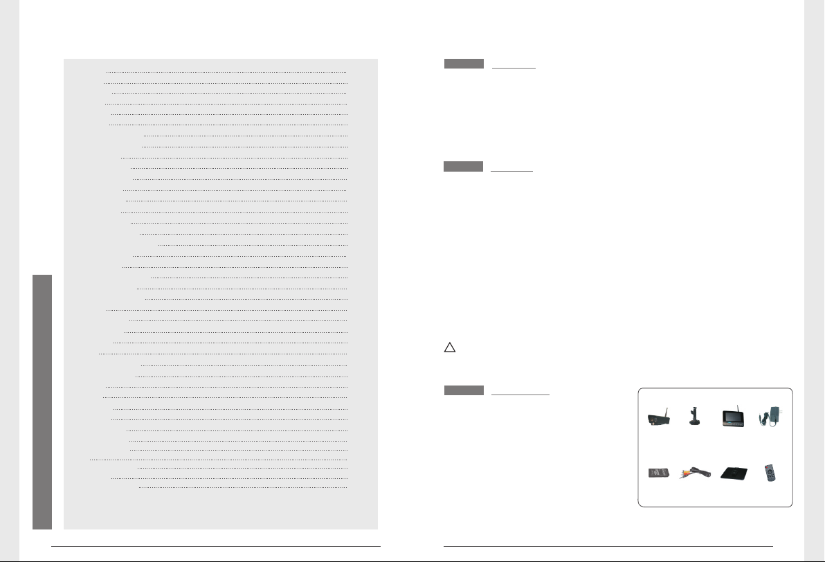
Packing List
① Camera x 4
②
Bracket for
③
7"TFT LCD
④ Adapter x 5
⑤ SD Card(optional) x 1
⑥ AV Output Cable x 1
⑦ Bracket for Monitor (optional) x 1
⑧ (optional) x 1Remote control
* The pictures are for reference only, please refer to real subjects.
Camera x 1
Monitor
x
1
① ③②
⑤ ⑥
④
⑦ ⑧
02
Page 3
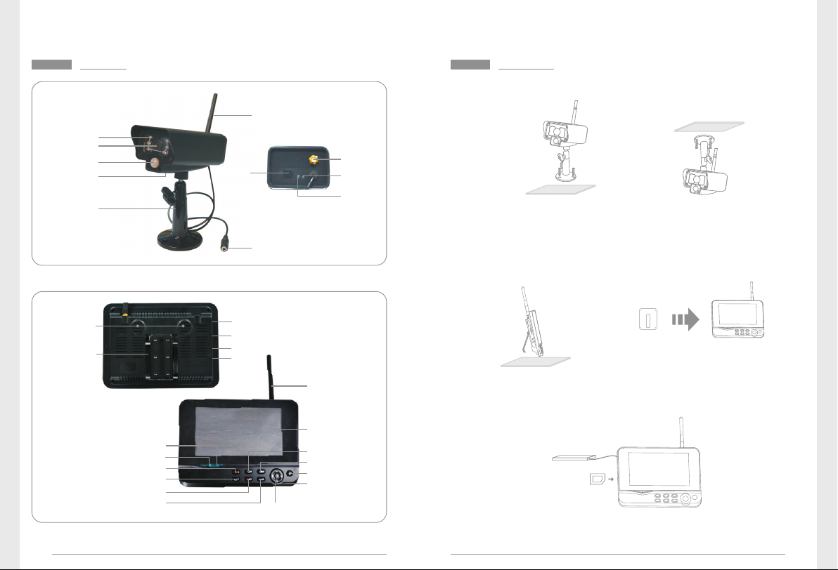
Structure
Infrared LEDs
Lens
PIR infrared
sensor
Microphone
Bracket
Pair
Button
Antenna
Power Input
Antenna
Socket
Link
Indicator
Power
Indicator
Installation
1. Install the camera at the proper monitoring location. The camera
can be installed in two modes:
① Upright installation:
Install the camera
on a level plane.
2. Install the receiver at a proper location. This receiver is provided
with two kinds of brackets, so it can be installed in two modes:
② Reverse installation:
Install the camera in
the celilng.
Microphone
Bracket
Link Indicator
Power Indicator
Record/stop Video
Quarter Display Button
Delete file/LCD、TV Switch
03
Menu
USB Port
SD Card Slot
AV Output
Power
Port
Navigate Button
Antenna
7"TFT-LCD
Display Mode
Playback Video
Power on/off
OK Button
Use screws to
fix the bracket
to the wall.
① Positioned on a level plane ② Mounted to the wall
Clamp the
receiver on
the bracket
3. Insert the SD card or connect an external storage device, such
as a mobile hard disk.
Note: It doesn’t support hot plugging of SD card or external storage
device.
04
Page 4
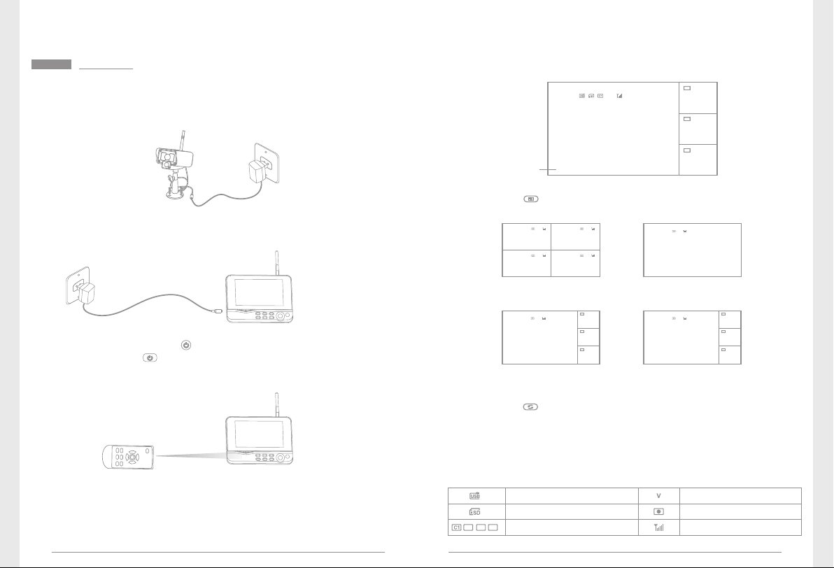
Operations
● Basic operations
1. Connect the camera to the power supply. The power Indicator
on the back is turned on:
5. A ft er s uc ces sf ul pai ri ng , th e f ollow in g re al -t ime mo ni tor in g
picture appears:
C2
Picture display area
2011/11/05/09:30
C3
Picture display area
2011/11/05/09:30
C4
Picture display area
2011/11/05/09:30
Time stamp
V
Picture disp lay area
2011/11/05/09:30
6. Press the button to switch between four display modes:
2. Connect the receiver to the power supply.
3. Press the power switch on the receiver for 2s. or press
the power swi tch on the remo te control(di rect the remot e
control toward the receiver).
The power indicator is turned on and the power-on picture
appears.
4. Pair the cameras and receiver respectively (at most four cameras
can b e conn ecte d at th e same time ). Pairi ng is compl eted b y
def aul t be for e delive ry. If p air ing is not co mpl ete d, c ompl ete
pairing according to “Pairing” on page 16.
05
V
Picture display area Picture display area
2011/11/05/09:30
2011/11/05/09:30 2011/11/05/09:30
2011/11/05/09:30
Picture display areaPicture display area
V
Picture display area
2011/11/05/09:30
Four pictures One picture
V
Picture display area
2011/11/05/09:30
One large picture and
three small pictures
7. Pre ss th e butt on to enter cycl ic mod e display. Fiv e cycl ic
interv als are available : 5s, 10s , 15s, 20 s, and 30 s and can
be set under “System”.
C2
Picture display area
2011/11/05/09:30
C3
Picture display area
2011/11/05/09:30
C4
Picture display area
2011/11/05/09:30
V
Picture display area
2011/11/05/09:30
One large picture and
three small picture
C2
图像显示区域
2011/11/05/09:30
C3
图像显示区域
2011/11/05/09:30
C4
图像显示区域
2011/11/05/09:30
Meanings of icons on the real-time monitoring picture:
Mobile hard disk inserted
successfully
SD card inserted successfully
C3
C2
C4
Camera name
Current camera
Recording status
Signal intensity
06
Page 5

● Video recording
Manual Recording:
1. In the real-time m onitorin g status, press the and buttons
to select the camera for video recording as the current camera.
2. Press the recording/stopping button on the device.
The recording icon is displayed on the screen, indicating that
recording starts.
3. Press the button on the device again to stop recording.
Timer Recording:
Set the recording start/stop time through the “Timer Recording”
men u. The de vi ce a ut oma ti ca lly re cords ac cor di ng to t he set
start/stop time. After recording, it automatically saves the video.
Specific steps are as follows:
1. Press the MENU button to enter setting interface;
2. Pre ss the or but ton to selec t “Record” and pr ess th e OK
button to enter;
3. Press the or button to select “Timer Recording” and press
the OK button to enter;
4. Press the or button to select “New Schedule” and press the
OK button to enter:
Timer Recording
Camera
Date
Start Time
End Time
OK:Options MENU:Quit
Press the or button to select;
Press the or button to adjust;
Press the OK button to confirm and exit;
5. After setting, the device automatically records according to the
set start/stop time.
6. If you pres s the r ecord ing/s toppi ng but ton on the device
during the recording process, recording stops.
All Cameras
11/6/2012 Tue
00:00
:
0000
PIR Recording:
If there is human motion detected by any accessed camera, recording
can be triggered. The specific steps are as follows:
1. Press the MENU button to enter the setting interface;
2. Press the or button to select “Record”, press the OK button
to enter;
3. Press the or button to select “PIR Recording”, press the OK
button to enter;
4. Press the or button to select the camera;
5. Press the or button to select “On”;
6. Press the OK button to confirm and exit.
* When “Off ” is s et, m otion detection funct ion i s turn ed of f.
* The infrared sensing distance of PIR is 5 m. If the distance exceeds
5m, sensing may fail.
Remarks:
1. If the video recording time is longer than 5 minutes, a video file
will be automatically saved every 5 minutes.
2. M ul tip le cha nn els (f ou r ch an nel s a t mo st ) of re cordi ng are
supported at the same time. The recorded video of each channel
is saved in an independent video file.
● Playback
1. In the real-time status, press the button to enter playback
interface;
2. Press the or button to select the folder;
3. Press the OK button confirm and enter:
/mnt/usb/re c/20121107 2/5
.. (up) <DIR >
Camera 1
Camera 2
Camera 4
065304-1.a vi 5MB
065320-2.a vi 7MB new
065354-2.a vi 5MB new
065417-4.a vi 10MB new
'Enter':Pla y 'Del':Del ete
Not browse d
File size
07
08
Page 6

4. Press the or button to select video;
5. Press the OK button to playback:
C2
V
Picture disp lay area
2011/11/05/09:30
Press the / button to go
backward/forward fast;
press the OK button again
to pause; press the MENU
button to quit the play mode.
Picture display area
2011/11/05/09:30
C3
Picture display area
2011/11/05/09:30
C4
Picture display area
2011/11/05/09:30
● Delete Video
1. In the video playback mode, press the and buttons to select
the video or video folder to be deleted.
2. Press the button on the device to delete it.
Remarks:
Only the empty folder can be deleted.
● Video Output
You can con nect the receiver to a larger moni tor/TV to m onitor
video more clearly.
Video Cable
Press the button to switch display between the monitor/TV and
the receiver.
System Setting
In t he r ea l-t im e stat us , pres s t he M EN U bu tt on to e nt er the
following interface:
Press the or button to select “system” and then press the OK
button to enter the system setting interface:
System
Date / Time
Language
Record Mode
Format SD/USB
OK:Options MENU:Quit
Date / Time
Language
Record Mode
Format SD/USB
Storage for Recording
Display Items
TV System
System Information
Scan Mode Period
Mute
Load Default
Record Date/Time
Brightness
Volume
Sets the system time and date.
Sets the system language.
Sets to stop recording or overwrite the earliest video record when the
storage medium is full.
Sets whether to format the storage medium.
Sets the storage medium.
Sets whether to display RSSI, Time, SD/USB Status and Camera on the
screen and the recorded video.
Selects a system.
Views the system information.
Sets the cyclic display interval of monitoring picture on the camera.
Turns on/off the speaker on the receiver.
Sets whether to restore default settings.
Sets whether to display the current recording time and date on the recorded video.
Adjusts brightness of the LCD screen.
Adjusts the sound.
09
10
Page 7

Press the or and buttons to select an option, and then press
the OK button to confirm.
● Date / time
Press the OK button to enter:
Date / Time
/ /
23
Date
Time
11
:
05
11
2011
OK:Options MENU:Quit
Press the or button to select;
Press the or button to adjust;
Press the OK button to confirm;
Press the MENU button to exit.
● Format SD/USB
1. Press the OK button to enter;
2. Press the or button to select “Cancel”, “SD Card” or “USB Device”;
Cancel: Cancels formatting.
SD Card: Formats the SD card.
USB Device: Formats the USB device.
3. Press the OK button to format:
Format SD/USB
Formatting, please wait.....
OK:Options MENU:Quit
4. After formatting, the system prompts “Format Successfully”,
indicating that formatting succeeds.
● Language
1. Press the OK button to enter;
2. Press the or button to select language and then press the
OK button to confirm and exit.
● Record Mode
1. Press the OK button to enter;
2. Press the or button to select “Normal” or “Overwrite” and
then press the OK buton to confirm and exit.
Remarks:
Nor mal : Wh en the SD c ard or the mob ile har d d isk is f ull , t he
system stops recording automatically.
Overwrite: When the SD card or the mobile hard disk is full, the
sy st em au tom at ic al ly d el et es the ea rl ie st vid eo s a nd
res erve s a s uffi cien t storag e spa ce to gua rant ee th is
recording.
11
● Storage for Recording
1. Press the OK button to enter;
2. Press the or button to select “SD Card” or “US B Device”;
3. Press the OK button to confirm and exit.
● Display Items
1. Press the OK button to enter;
2. Press the or button to select;
3. Cli ck the OK bu tton t o con firm w hether to d ispla y thi s item .
If this i tem is dis played, the icon appears behind this item.
RSSI: Signal intensity icon, icon :
SD USB status: Whether the SD car d or mobile hard disk i s
inserted, icons :
Camera: Camera name, icons :
4. After setting, press the MENU button to confirm and exit.
C3
C2
C4
12
Page 8

● TV System
1. Press the OK button to enter;
2. Press the or button to select;
3. Press OK button to confirm and exit.
● System Information
1. Press OK button to enter and view;
2. Press the MENU button to exit.
● Mute
1. Press the OK button to enter;
2. Press the or button to select “On” or “Off”;
3. Press the OK button again to confirm and exit.
● Load Default
1. Press the OK button to enter;
2. Press the or button to select “Cancel” or “OK”;
Cancel: Cancels restoration of default settings.
OK: Restores default settings.
3. Press the OK button to confirm and exit.
● System Update
1. Press the OK button to enter;
2. Press the or button to select;
3. Press OK button again to adjust;
4. Press button to confirm and exit.
● Scan Mode Period
1. Press the OK button to enter;
2. Press the or button to select;
3. Press OK button again to confirm and exit.
13
● Brightness
1. Press the OK button to enter;
2. Press the or button to adjust;
3. Press the OK button to confirm and exit.
● Volume
1. Press the OK button to enter;
2. Press the or button to adjust;
3. Press the OK button to confirm and exit.
14
Page 9

Record
1. In t he re al-time st atus , pre ss the MENU butt on to enter the
following interface:
2. Press the or button to select “Record”;
3. Press the OK button to enter:
Record
Timer Recording
PIR Recording
OK:Options MENU:Quit
● Timer Recording
Set the recording start/stop time. The device automatically records
according to the set start/stop time. After recording, it automatically
saves the video record. For specific steps, see Page 07.
Playback
For specific steps, see Page 08.
Camera
1. In th e real-t ime sta tus, pr ess the MENU b utton t o enter the
following interface:
2. Press the or button to select “Camera”;
3. Press the OK button to enter:
Camera
Pairing
Active
PIP Setting
OK:Options MENU:Quit
● PIR Recording
If th er e i s hu ma n m ot i on de te cte d b y a ny a cc es se d c a me ra ,
recording can be triggered. For specific steps, see Page 08.
15
● Pairing
After pairing, the camera is not affected by interference of other
frequencies.
1. Press the or button to select “Pairing”, press the OK button
to enter:
Pairing
Camera-1
Camera-2 Paired 0xe01f0007
Camera-3 Paired 0xe01f0006
Camera-4 Paired 0xe01f0005
OK:Options MENU:Quit
Paired
0xe01f0008
16
Page 10

2. Press the or button to select camera;
3. Press the OK button to pair:
Pairing
Camera-1
Camera-2 Paired 0xe01f0007
Long press the PAIR button on TX for 2 seconds
Camera-3 Paired 0xe01f0006
Camera-4 Paired 0xe01f0005
OK:Options MENU:Quit
4. Within 60s, press the Pairing button on the back of the camera
for 2s.
5. After successful pairing, the receiver screen displays the following
information:
Remarks:
If pai ri ng f ai ls, the sy ste m p rom pt s “Pa iri ng fai led”. Ple as e
perform pairing again.
Paired
Pairing.....
52
Pairing OK
Congratulations!!!
0xe01f0008
● Active
1. Press the or button to select “Active”, press the OK button
to enter:
Active
Camera-1
Camera-2
Camera-3
Camera-4
OK:Options MENU:Quit
2. Press the or button to select the camera;
3. Press the or button to select “On” or “Off”;
4. Press the OK button to confirm and exit.
Off
On
Paired
On
Paired
On
Paired
Special not e: When “O FF” is se t, th e camera does not h ave any
action, such as monitoring picture display, recording, or automatic
alarm.
● PIP Setting
Set the resolution and pixels for the recorded video.
1. Press the or but ton to sel ect “PIP Setting ”, press the OK
button to enter:
PIP Setting
Camera-1 Low High
Camera-2 High
Camera-3 High
Camera-4 HighHigh
OK:Options MENU:Quit
2. Press the or button to select the camera;
3. Press the OK button to enter the following interface:
High
High
17
18
Page 11

Base/PIP Setting
Resolution Size
High
Low
OK:Options MENU:Quit
Press the or button to select “Resolution Size” or “Quality”;
Press the or button to select “Top”, “High”, “Medium” or “Low”;
Press the OK button to adjust;
Press the MENU button to confirm and exit.
Quality
Top
High
Medium
Low
Alarm Setting
Here, you can set whether to send an alarm automatically when
any motion detected by the camera:
1. In the real-time status, press the “MENU” button to enter setting
interface;
2. Press the or button to select “Alarm”;
3. Press the OK button to enter;
4. Press the or button to select “On” or “Off”;
5. Press the OK button to confirm and exit.
Specifications
Items
Imaging Sensor
Video Resolution
Viewing Angle
Power Supply
Consumption Current (Max.)
Camera
Waterproof Capacity
Unobstructed Effective Range
Night Vision Distance
Dimensions( W x D H ) x
Approx. Weight
LCD Screen Type
LCD Screen Resolution
SD Card
Hard Disk
Video Frame Rate
Video Resolution
Video Format
Date Output
Monitor
Unobstructed Effective Range
Power Supply
Consumption Current (Max.)
Dimensions( W x D H ) x
Approx. Weight
Operating Temperature
Operating Humidity
* All the specifications are subject to minor change without prior notice.
8104JM
1/ -inch5 color CMOS
656 x 488
70°
5V
400mA
IP54
200m (Min.)
5m (Max.)
131 (mm) (exclude the bracket)x 63 x 58
282g
7"TFT LCD
800*480
Supports to 32GB
Supports to 1TB
30fps max.( )
CIF/VGA
.AVI
USB 2.0
200m (Min.)
5V
700mA
214 (mm)x 157 x 26
492g
-10℃~50℃
15~85%RH
19
20
Page 12

FAQ
1. Why does not the screen display any monitoring picture after
the camera is connected?
Answer: 1. Please check whether “Active” is set to “ON”.
2. Please check whether pairing succeeds.
2. The recordin g time is set already or the human body sensing
recording is enabled, but the receiver does not start recording
when the time comes or a human body is sensed. Why?
Answer: 1. Check whether the storage medium is inserted.
2. Check whether the storage medium is full.
3. The system does not respond when the playback button is
pressed. Why?
Answer: Please check whether the current camera is in the recording
stat us. I f it is in th e reco rdin g status, t he system w ill n ot
respond when this button is pressed.
FCC Information
This device complies with part 15 of the FCC Rules. Operation is
subject to the following two conditions:
(1) This device may not cause harmful interference;
(2) This de vice must a ccept any i nterference receiv ed, includ ing
interference that may cause undesired operation. Changes or
modifications not expressly approved by the party responsible
for compliance could void the user ’s authority to operate the
equipment.
Warnings
● This product shall not be exposed to water either by dripping,
splashing, immersing, etc., unless otherwise indicated.
● Turn off the system if it is not in use.
● This product can only be completely disconnected for from its
power source by unplugging the power adapter.
● Do not cut the DC power cable of provide d with this pr oduct
to fit with another power source.
21
22
Page 13

IMPORTANT NOTE:
FCC Radiation Exposure Statement:
This equipment complies with FCC radiation exposure limits set forth for an
uncontrolled environment .This equipment should be install ed and operated with
minimum distance 20cm between the radiator& your body.
This transmitter must not be co-located or operating in conjunction with any other antenna or
transmitter.
 Loading...