

Page 1
Quick Start Guide
Digital Wireless Camera System
Model: 8902JN
8902JN = GL8902(Camera)+GT4067(Transmitter)+GD7067(Receiver)
Receiver
Prompt:
1, this product is suitable for 12V power car;
2, please find auto electrician to install this product;
3, the wire harness to avoid high temperature and
high pressure location;
4, broken wiring must be insulated.
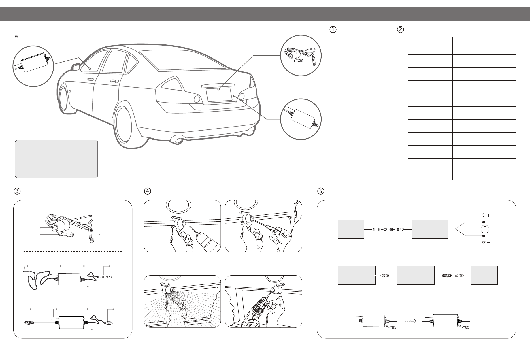
Product Structure: Installation Wired Camera:
Camera
Transmitter
Packing List:
W GL8902ired camera: X 1
Wireless transmitter: X 1GT4067
Wireless receiver: GD7067 X 1
Specifications:
Image Sensor
Effective Pixels
Video Format
View Angle
Minimum illumination
Camera
TransmitterReceiver
Video output
Power Supply
Consumption Current
Waterproof Capacity
Transmission Frequency
Data Bandwidth
Modulation/Demodulation Mode
Transmission Power
Receiving Sensitivity
Unobstructed Effective Range
Power Supply
Consumption Current
Dimensions (W X D X H)
Weight
Transmission Frequency
Data Bandwidth
Modulation/Demodulation Mode
Transmission Power
Receiving Sensitivity
Unobstructed Effective Range
Power Supply
Video output
Dimensions (W X D X H)
Weight
Operation Temperature
Operation Humidity
Wiring diagram and the pairing setting:
1/4" CMOS
656 X 488
NTSC/PAL
O O
80 (NTSC), 82 (PAL)
<0.5 Lux
1Vp-p±0.2@75Ω
DC12V±0.5V
65mA±10
IP6 6
2400~2483.5MHz
4.4 (20dB BW)
QPSK
+18dBm@QPSK
EVM 8%
-72dB
50M (MAX.)
DC 12~24V
DC 12V@250mA; DC24V@150mA
66 X 35 X 12mm
60g
2400~2483.5MHz
4.4 (20dB BW)
QPSK
+18dBm @ QPSK
EVM 8%
-72dB
50M (MAX.)
DC 12~24V
1Vp-p±0.2
66 X 35 X 12mm
60g
O O O O
-10 C~+50 C/14 F~122 F
15%~85%RH
Wired camera(GL8902)
Camera Lens
Bracket
Wireless transmitter )(GT4067
Connect the vehicle
power supply
Antenna
Indicator
Pairing
Wireless receiver )(GD7067
Power input
(Connected with a
cigarette lighter)
Antenna
Indicator
Pairing
Video Output
Video Input
Video Output
1. In the proper position of rear license plate
drill a screw hole for mounting screw.
3. Move the camera orientation to adjust
the display effect.
2. Use a screwdriver to the first screw is screwed
into the screw hole of the drilled.
4. After adjustment, second screw drill, mount and
tighten the screws, the camera is installed.
Wired camera+Wireless transmitter:
Red line
Wired camera
(GL8902)
Wireless Transmitter
(GT4067)
Black line
Rear
lamp
Wireless receiver:
Display or Monitor
Video input
Pairing: To pair the TX box and RX box successfully. please follow the instructions below accordingly.
1. Press and hold the pairing button on the TX box for 3sec. The indicator light will start flashing.
2. Within 30sec of flashing time. Press and hold the pairing button on the RX box for 3sec until the indicator light flashes.
3. Once both TX box and RX box are successfully paired. the indicator lights on TX box and RX box will stop flashing.
Wireless Transmitter
Wireless Receiver
)(GD7067
Pair button Pair button
Wireless Receiver
Cigarette lighter
power supply
Page 2

FCC Warning Statements:
Changes or modifications not expressly approved by the party responsible for compliance could
void the user’s authority to operate the equipment.
This equipment has been tested and found to comply with the limits for a Class B digital
device, pursuant to part 15 of the FCC Rules. These limits are designed to provide reasonable
protection against harmful interference in a residential installation. This equipment generates, uses
and can radiate radio frequency energy and, if not installed and used in accordance with the
instructions, may cause harmful interference to radio communications. However, there is no
guarantee that interference will not occur in a particular installation. If this equipment does cause
harmful interference to radio or television reception, which can be determined by turning the
equipment off and on, the user is encouraged to try to correct the interference by one or more of
the following measures:
- Reorient or relocate the receiving antenna.
- Increase the separation between the equipment and receiver.
-Connect the equipment into an outlet on a circuit different from that to which the receiver is
connected.
-Consult the dealer or an experienced radio/TV technician for help.
“RF Exposure Guidance: This equipment complies with FCC radiation exposure limits set forth for
an uncontrolled environment. This equipment should be operated with a minimum distance of
20cm between the radiator and persons. This transmitter must not be co-located or operating in
conjunction with any other antenna or transmitter, except in accordance with FCC
multi-transmitter product procedures.”
 Loading...