

Page 1
Model:8912W
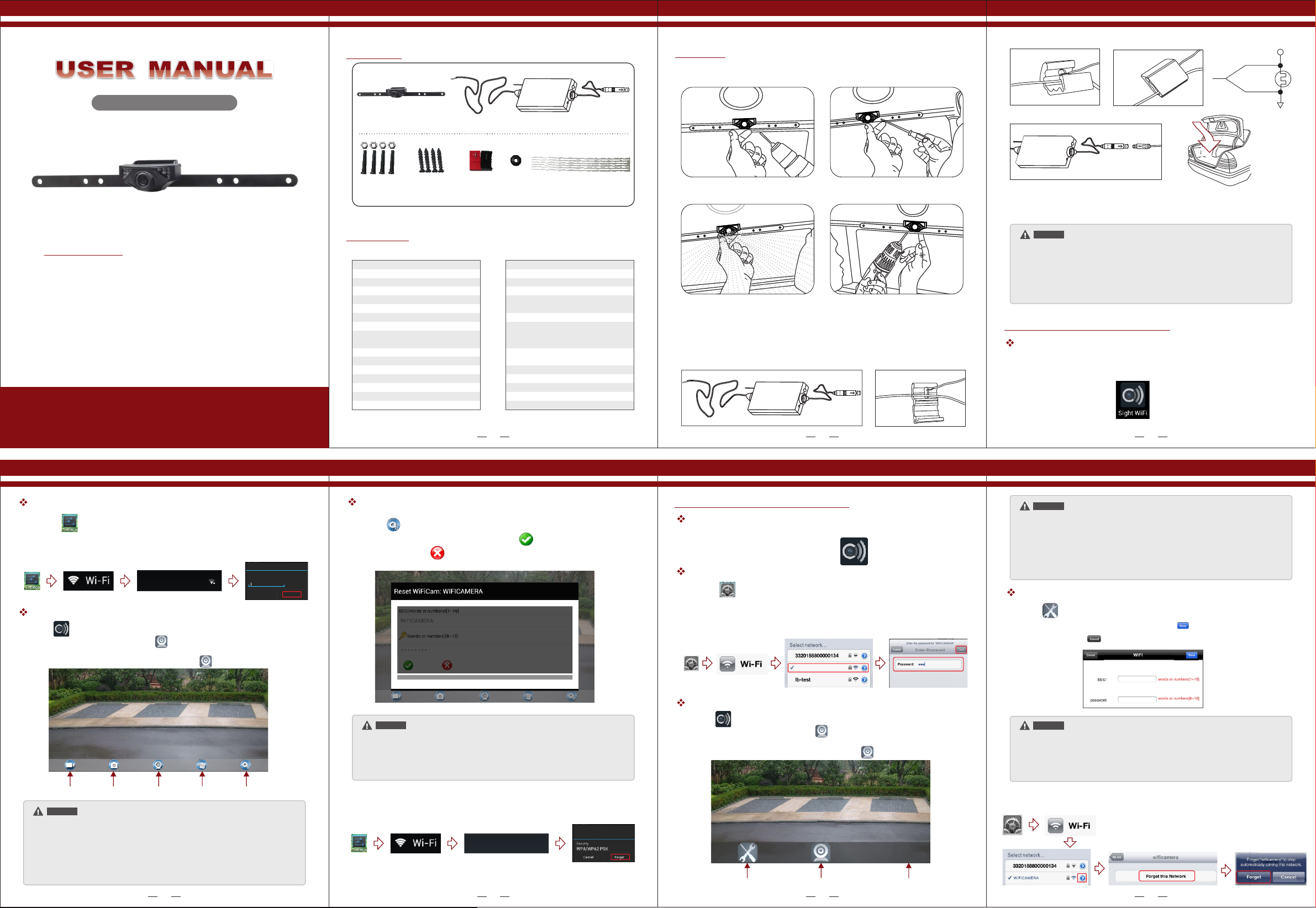
Packing List
Camera
Emitter
Installation
Ins ta ll ati on i ns tru ct io ns fo r th e ca mer a:
Red +
rear lamp
Bla ck -
Product Features
● The device uses its WIFI module for wireless video
signal transmission.
● The client can use iOS and Android APP in the
intelligent mobile phone to view the real-time
camera video, so as to carry out real-time video
monitoring for the scenes of the rear view of the
car, and it is easy to install and use.
● The client terminal shall support Android 2.2 or
above, and iOS shall support Version 4.3 or above.
Version 1.0
Please read this user manual carefully before using this product.
Failure to understand operation procedures may result in injury.
* The pictures are for reference only, please refer to real subjects.
License Plate
Nuts & Bolts
License Plate
Screws (Optional)
In-Line Wire
Connectors
Grommet
Specifications
WIFI car rear view
Items
Power Supply
Consumption Current
Video output
Night Vision Range
Image Sensor
Effective Pixels
Video Format
Electronic Exposure Time
Minimum illumination
Horizontal View Angle
Operation Temperature
Storage Temperature
Operation Humidity
Dimensions
Weight
* All the specifications are subject to minor change without prior notice.
GL8912
12V DC
150mA MAX
0.9 . Vp-p 75Ω ~1 2
>3m
1/4inch CMOS
640×480 pixels
NTSC/PAL
1/60s-12ns(NTSC) sec
1/50s-12.5ns(PAL) sec
<5 Lux
O
80
O
-10~ C+50
O
-20~ C+60
15%~85%RH
370 X 55 X 35MM
140g
Items
Operation Voltage
Operation Current
Operation Frequency
Wireless Protocol
Encryption Mode
Modulation Mode
Transmission Distance
With No Obstacle
Weight
Dimensions
Operation Temperature
Storage Temperature
Operation Humidity
Cable Ties
WIFI transmitter box
GT4068
12V DC
150mA(MAX)
2400-2483.5MHz
IEEE 802.11b, IEEE 802.11g,
IEEE 802.n (1T1R Modes)
WPA2
802.11b:DSSS (CCK, DQPSK,
DBPSK)•802.11g/n:OFDM
(BPSK, QPSK, 16QAM, 64QAM)
≥10m
60±5g
71 X 35.5 X 12.3MM
-10~ C+50
-20~ C+60
20%~90%RH
1. In the proper position of rear license plate
drill a screw hole for mounting screw.
2. Use a screwdriver to the first screw is
screwed into the screw hole of the drilled.
When the camera is fixed, put the lead-wire of the camera through the car trunk.
Notice
*
The positive and negative pole of the power cable of the emitter box are connected
to the positive and negative pole of the rear lamp of the car.
Never reverse the positive and negative pole. Otherwise the emitter box and the
*
camera can be damaged and cannot be used.
The antenna of the emitter box shall not be near any metal part of the car. Otherwise
*
the emitting distance and the image transmission effect can be influenced.
3. Move the camera orientation to adjust
the display effect.
Ins ta ll ati on i ns tru ct io ns fo r th e em itt er :
4. After adjustment, second screw drill,
mount and tighten the screws, the camera
is installed.
Operations for Android system client
Installation APP software:
1. Turn on the intelligent mobile device terminal and enter GOOGLE PLAY store.
2. Search "Sight WIFI" software, and download.
3. Install the APP software. as the following interface:
O
O
2 31
Connection WiFi:
1. Click the " " icon in the main interface of the intelligent mobile device terminal.
2. Click " Wi-Fi ", select your camera, and t the wifi of the intelligent mobile device terminal
to the wifi of the tool. The initial SSID of the is WIFICAMERA . Then type in the device " " password
of the device (Default password: 88888888). As shown below:
connec
WIF ICAME RA
Secu red wit h WP2
WIFIC AMERA
Securi ty
WP2 PSK
Passwo rd
Conne ct Cance l
View the video:
Ope n the AP P, and if the connec tio n bet wee n the w ifi o f the tool and the int ell ige nt
mob ile d evi ce te rmina l is succe ssf ul, t he ic on wi ll be h igh lig hte d, an d the i mag es
tra nsm itted from the wifi camer a too l can be seen i n the AP P, as show n in th e fig ure .
in th e rea l-t ime m oni torin g mod e, th e use r can pres s the icon to revers e the imag e.
Record
a video
Take a
photo
camera
Video/
Photo
playback
Settings Connecting
Notice
* When set WIFI signal to connect the mobile phone, please close the WIFI signal
previously opened.
* ,
image display time is relate to the CPU memory, software version, working
software number of mobile phone.
* when the background is black or the image is still, please exit the APP, and check
whether the wifi connection is normal. then click again the APP icon to enter into
the software interface.
4
Settings:
Press this icon to enter into the settings menu. You can change the default factory
SSID and password of the wifi camera tool, and clicking will show whether the change
is successful, and clicking to cancel the new SSID set.
Notice
* User could press the RESET button of the emitter to renew the default factory
SSID and password.
* When the user changes the SSID and password, the user shall forget the network
in the "Settings" , and then reconnect the new network. Otherwise login error will
remain displayed.
The specific steps to clear network memory are as follows.
connection method to reconnect the new network.
WIF ICAME RA
Not in r ange
and then follow the above WIFI
WIFIC AMERA
Operations for iOS Apple system client
Installation APP software:
1. Turn on the intelligent mobile device terminal and enter APP Store.
2. Search "Sight WIFI" software, and download.
3. Install the APP software. as the following interface:
Connection WiFi:
1. Click the " " icon in the main interface of the intelligent mobile device terminal.
2. Click " Wi-Fi ", select your camera, and t the wifi of the intelligent mobile device terminal
to the wifi of the tool. The initial SSID of the is WIFICAMERA . Then type in the device " " password
connec
of the device (Default password: 88888888). As shown below:
WIFI CAMER A
View the video:
Ope n the AP P, and if the connec tio n bet wee n the w ifi o f the tool and the intell ige nt
mob ile d evi ce te rmina l is succe ssf ul, t he ic on wi ll be high lig hte d, an d the i mag es
tra nsm itted from the wifi camer a too l can be seen i n the AP P, as show n in th e fig ure .
in th e rea l-t ime m oni torin g mod e, th e use r can pres s the icon to revers e the imag e.
G
Settings Connecting camera
6
LOGO
Notice
* When set WIFI signal to connect the mobile phone, please close the WIFI signal
previously opened.
image display time is relate to the CPU memory, software version, working
* ,
software number of mobile phone.
* when the background is black
whether the wifi connection is normal. then
or the image is still, please exit the APP, and check
click again the APP icon to enter into
the software interface.
Settings:
Press this icon to enter into the settings menu. You can change the default factory
SSID and password of the wifi camera tool, and clicking will show whether the change
is successful, and clicking to cancel the new SSID set.
Notice
* User could press the RESET button of the emitter to renew the default factory
SSID and password.
* When the user changes the SSID and password, the user shall forget the network
in the "Settings" , and then reconnect the new network. Otherwise login error will
remain displayed.
The specific steps to clear network memory are as follows.
and then follow the above WIFI
connection method to reconnect the new network.
75
Page 2

FCC Statement
NOTE: This equipment has been tested and found to comply with the limits for a Class B digital device, pursuant to part 15 of the FCC Rules.
These limits are designed to provide reasonable protection against harmful interference in a residential installation. This equipment generates
uses and can radiate radio frequency energy and, if not installed and used in accordance with the instructions, may cause harmful interference
to radio communications. However, there is no guarantee that interference will not occur in a particular installation. If this equipment does cause
harmful interference to radio or television reception, which can be determined by turning the equipment off and on, the user is encouraged to try
to correct the interference by one or more of the following measures:
- Reorient or relocate the receiving antenna.
- Increase the separation between the equipment and receiver.
-Connect the equipment into an outlet on a circuit different from that to which the receiver is connected.
-Consult the dealer or an experienced radio/TV technician for help
This device is acting as slave and operating in the 2.4 GHz (2412 ~2462 MHz) band.
Ad Hoc function is supported but not able to operate on non-US frequencies.
Changes or modifications not expressly approved by the party responsible for compliance could void the user's authority to operate the equipment.
This device complies with Part 15 of the FCC Rules. Operation is subject to the following two conditions:
(1) this device may not cause harmful interference, and
(2) this device must accept any interference received, including interference that may cause undesired operation.
FCC Radio Frequency Exposure Statement
The device has been evaluated to meet general RF exposure requirements.
The min separation distance is 20cm.
The device can be used in fixed/mobile exposure conditions.
 Loading...