

Goscam 8104JM, GD8104, GD7104 User Manual
01
02
CONTENTS
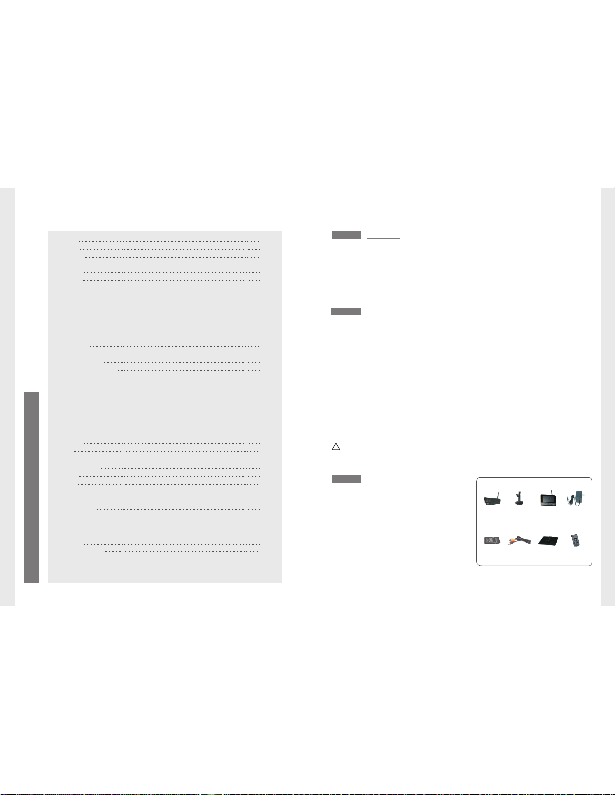
① Camera x 4
②
7"TFT LCD
Monitor
x
1
③
④ Adapter x 5
⑤ SD Card(optional) x 1
⑥ AV Output Cable x 1
⑦ Bracket for Monitor (optional) x 1
⑧ (optional) x 1Remote control
Packing List
Welcome
This product is a household monitoring recording device. It consists
of four cameras installed at entrances/exits of the home and one
DVR receiver with a 7-inch LCD monitor. The four-split screen of
the receiver can display the monitoring pictures of four accessed
cameras. In addition, the infrared sensing alarm function of human
body is available. Thus, a household closed monitoring system is
presented.
* The pictures are for reference only, please refer to real subjects.
For 8105JM, the camera has IR-cut function and image
effect is better than 8104JM .
Bracket for
Camera x 1
⑦ ⑧
① ③②
⑤ ⑥
④
Features
● 4CH digital wireless camera & DVR system;
● Simple installation- no cables required;
● Total digital wireless, no interferences, no privacy leak;
● 7” LCD monitor with integrated video recorder;
● Support up to 32GB SD card or external mobile disk by USB2.0
(up to 1TBmobile disk);
● Support 4 cameras/ 24hours /7days non-stop overwrite
recording;
● Multiple recording modes: manual,schedule, and motion activated;
● 5m night vision range;
● Video quality: 4CH VGA 10fps, 1CH VGA 30fps;
● Weather proof outdoor cameras with 300m/1000ft transmission
open range;
● Video output function for bigger monitor.
● IR-cut function. (only for 8105JM)
!
Please know that this monitor is not a PC, so some of the memory
devices may not work on this monitor.
Welcome
Features
Packing List
Structure
Installation
Operations
● Basic operations
● Video recording
● Playback
● Delete Video
● Video Output
System setting
● Date / time
● Language
● Record Mode
● Format SD/USB
● Storage for Recording
● Display Items
● TV System
● System Information
● Scan Mode Period
● Mute
● Load Default
● Brightness
● Volume
Record
● Timer Recording
● PIR Recording
Playback
Camera
● Pairing
● Active
● PIP Setting
Alarm setting
Specifications
FAQ
FCC Information
Warnings
02
02
02
03
04
05
05
07
08
09
09
10
11
11
11
12
12
12
13
13
13
14
14
14
14
15
15
15
16
16
16
18
18
19
21
20
21
21
● System Update
13
Troubleshooting
22
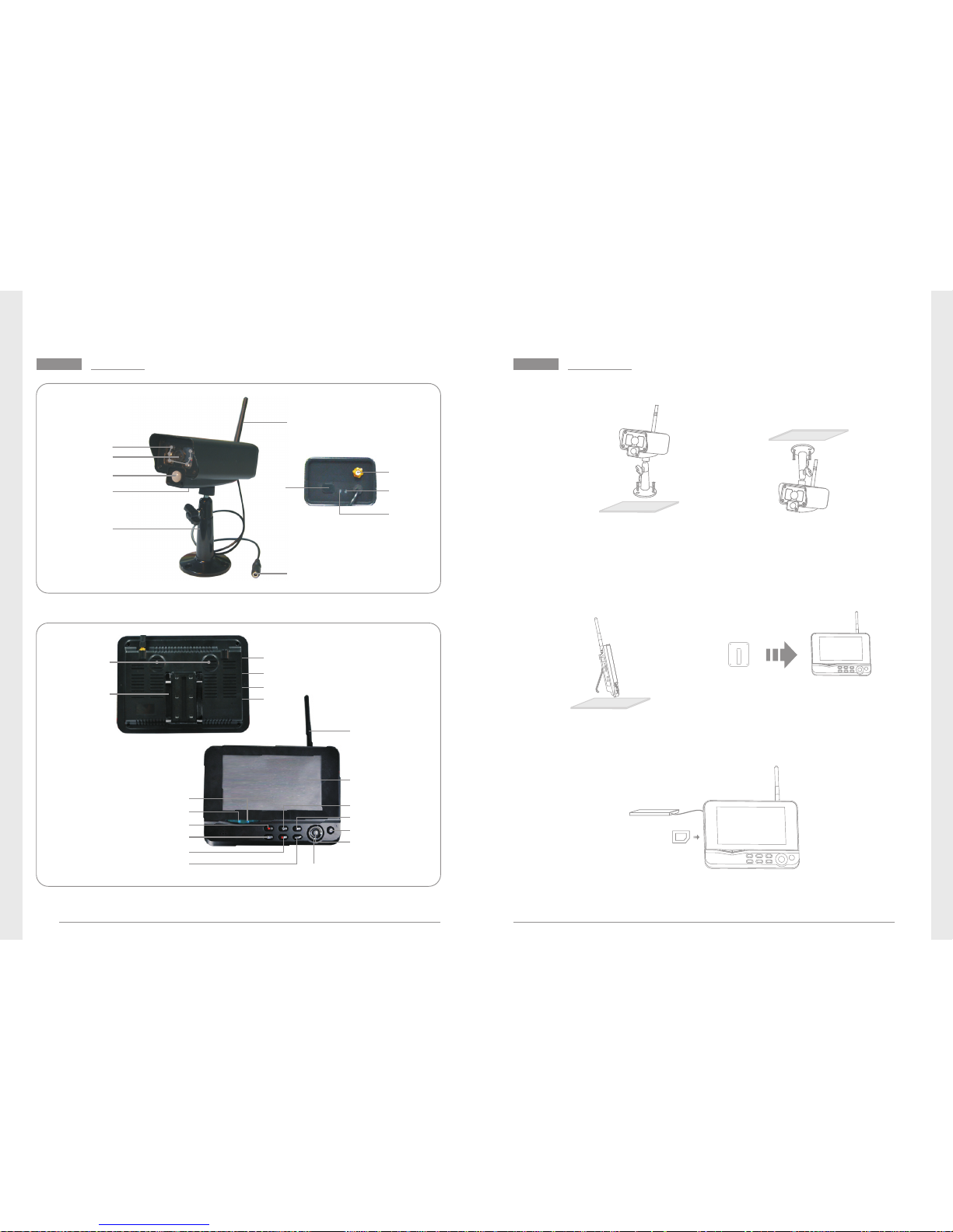
Structure
03
04
Installation
1. Install the camera at the proper monitoring location. The camera
can be installed in two modes:
3. Insert the SD card or connect an external storage device, such
as a mobile hard disk.
Note: It doesn’t support hot plugging of SD card or external storage
device.
Antenna
7"TFT-LCD
Power on/off
OK Button
Navigate Button
Delete file/LCD、TV Switch
Menu
Record/stop Video
Playback Video
Quarter Display Button
Display Mode
Microphone
Bracket
USB Port
SD Card Slot
AV Output
Power
Port
Link Indicator
Power Indicator
Antenna
Power Input
Infrared LEDs
Lens
Bracket
Antenna
Socket
Link
Indicator
Power
Indicator
Pair
Button
Microphone
① Upright installation:
Install the camera
on a level plane.
② Reverse installation:
Install the camera in
the celilng.
2. Install the receiver at a proper location. This receiver is provided
with two kinds of brackets, so it can be installed in two modes:
① Positioned on a level plane ② Mounted to the wall
Use screws to
fix the bracket
to the wall.
Clamp the
receiver on
the bracket
PIR infrared
sensor
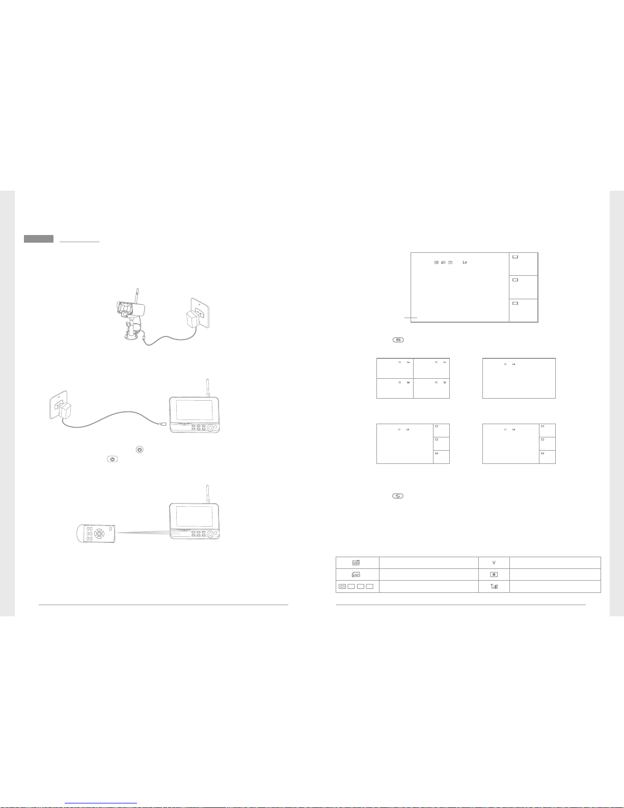
Operations
05
06
● Basic operations
1. Connect the camera to the power supply. The power Indicator
on the back is turned on:
3. Press the power switch on the receiver for 2s. or press
the power switch on the remote control(direct the remote
control toward the receiver).
The power indicator is turned on and the power-on picture
appears.
4. Pair the cameras and receiver respectively (at most four cameras
can b e connecte d at th e same time ). Pairi ng is compl eted b y
defaul t be for e delive ry. If p air ing is not co mpl ete d, c ompl ete
pairing according to “Pairing” on page 16.
2. Connect the receiver to the power supply.
6. Press the button to switch between four display modes:
V
2011/11/05/09:30
V
2011/11/05/09:30
C2
C3
C4
2011/11/05/09:30
2011/11/05/09:30
2011/11/05/09:30
V
2011/11/05/09:30
C2
C3
C4
2011/11/05/09:30
2011/11/05/09:30
2011/11/05/09:30
图像显示区域
图像显示区域
图像显示区域
Four pictures One picture
One large picture and
three small pictures
One large picture and
three small picture
7. Pre ss th e butt on to enter cycl ic mod e display. Fiv e cycl ic
interv als are available: 5s, 10s, 15s, 20s, and 30s and can
be set under “System”.
Meanings of icons on the real-time monitoring picture:
Mobile hard disk inserted
successfully
SD card inserted successfully
Camera name
Signal intensity
Recording status
Current camera
C2
C3
C4
V
2011/11/05/09:30
2011/11/05/09:30
2011/11/05/09:30 2011/11/05/09:30
5. A ft er s uc cessf ul pai ri ng , th e f ollow in g real -t ime mo ni tor in g
picture appears:
V
2011/11/05/09:30
C2
C3
C4
2011/11/05/09:30
2011/11/05/09:30
2011/11/05/09:30
Picture disp lay area
Time stamp
Picture display area
Picture display area
Picture display area
Picture display area Picture display area
Picture display areaPicture display area
Picture display area
Picture display area
Picture display area
Picture display area
Picture display area
Picture display area
 Loading...