

Gorman-Rupp Pumps VS6A60-B User Manual
CDSW
OM‐06014‐01
October 31, 2006
Rev. A 05‐28‐13
INSTALLATION, OPERATION,
AND MAINTENANCE MANUAL
WITH PARTS LIST
ULTRA V PUMP
MODEL
VS6A60-B
INCLUDING: /WW
THE GORMAN‐RUPP COMPANY MANSFIELD, OHIO
www.grpumps.com
GORMAN‐RUPP OF CANADA LIMITED ST. THOMAS, ONTARIO, CANADA Printed in U.S.A.
2006 The Gorman‐Rupp Company

Register your new
Gorman‐Rupp pump online at
www.grpumps.com
Valid serial number and e‐mail address required.
RECORD YOUR PUMP MODEL AND SERIAL NUMBER
Please record your pump model and serial number in the
spaces provided below. Your Gorman‐Rupp distributor
needs this information when you require parts or service.
Pump Model:
Serial Number:

TABLE OF CONTENTS
INTRODUCTION PAGE I - 1.................................................
SAFETY - SECTION A PAGE A - 1...........................................
INSTALLATION - SECTION B PAGE B - 1....................................
Pump Dimensions PAGE B - 1.....................................................
PREINSTALLATION INSPECTION PAGE B - 1............................................
POSITIONING PUMP PAGE B - 1.......................................................
Lifting PAGE B - 1.................................................................
Mounting PAGE B - 2.............................................................
Clearance PAGE B - 2.............................................................
SUCTION AND DISCHARGE PIPING PAGE B - 2.........................................
Materials PAGE B - 2..............................................................
Line Configuration PAGE B - 2......................................................
Connections to Pump PAGE B - 2..................................................
Gauges PAGE B - 2...............................................................
SUCTION LINES PAGE B - 2...........................................................
Fittings PAGE B - 2...............................................................
Strainers PAGE B - 2..............................................................
Sealing PAGE B - 3...............................................................
Suction Lines In Sumps PAGE B - 3.................................................
Suction Line Positioning PAGE B - 3................................................
DISCHARGE LINES PAGE B - 4........................................................
Siphoning PAGE B - 4.............................................................
Valves PAGE B - 4................................................................
Bypass Lines PAGE B - 4..........................................................
AUTOMATIC AIR RELEASE VALVE PAGE B - 5...........................................
Air Release Valve Installation PAGE B - 6............................................
DRIVE ARRANGEMENTS PAGE B - 7...................................................
Dual Motor Drives PAGE B - 7......................................................
Single Motor Belt Drives PAGE B - 7................................................
Single Motor Combination Drives PAGE B - 8........................................
HIGH PUMP TEMPERATURE SHUTDOWN FOR STAGED APPLICATIONS PAGE B - 9........
ALIGNMENT PAGE B - 9..............................................................
Coupled Drives PAGE B - 9........................................................
Drive Belts PAGE B - 10............................................................
DRIVE BELT TENSIONING PAGE B - 10..................................................
General Rules of Tensioning PAGE B - 10.............................................
OPERATION - SECTION C PAGE C - 1......................................
PRIMING PAGE C - 1.................................................................
STARTING PAGE C - 1................................................................
Rotation PAGE C - 1..............................................................
OPERATION PAGE C - 2..............................................................
Lines With a Bypass PAGE C - 2....................................................
Lines Without a Bypass PAGE C - 2.................................................
Leakage PAGE C - 2..............................................................
Liquid Temperature And Overheating PAGE C - 2.....................................
Strainer Check PAGE C - 3.........................................................
i

TABLE OF CONTENTS
(continued)
Pump Vacuum Check PAGE C - 3..................................................
STOPPING PAGE C - 3................................................................
Cold Weather Preservation PAGE C - 3..............................................
BEARING TEMPERATURE CHECK PAGE C - 3..........................................
TROUBLESHOOTING - SECTION D PAGE D - 1..............................
PREVENTIVE MAINTENANCE PAGE D - 3...............................................
PUMP MAINTENANCE AND REPAIR - SECTION E PAGE E - 1................
PERFORMANCE CURVE PAGE E - 1...................................................
PARTS LISTS:
VS6A60-B And VS6A60-B /WW Pump Models PAGE E - 3...........................
Pump Models 46167-041 And 46146-042 PAGE E - 5...............................
46146-001 Ultra Mate Pump Assembly PAGE E - 7...................................
Repair Rotating Assemblies PAGE E - 9.............................................
PUMP AND SEAL DISASSEMBLY AND REASSEMBLY PAGE E - 10.........................
Support Plare Removal PAGE E - 11.................................................
Back Cover And Wear Plate Removal PAGE E - 11.....................................
Rotating Assembly Removal PAGE E - 11.............................................
Impeller Removal PAGE E - 12......................................................
Seal Removal PAGE E - 12..........................................................
Shaft and Bearing Removal and Disassembly PAGE E - 12.............................
Pump Casing and Transition Chamber Removal PAGE E - 13...........................
Pump Casing and Transition Chamber Installation PAGE E - 14.........................
Shaft and Bearing Reassembly and Installation PAGE E - 14............................
Seal Installation PAGE E - 15........................................................
Impeller Installation And Adjustment PAGE E - 18......................................
Rotating Assembly Installation PAGE E - 18...........................................
Back Cover Installation And Adjustment PAGE E - 18..................................
PRESSURE RELIEF VALVE MAINTENANCE PAGE E - 19..................................
Final Pump Assembly PAGE E - 20..................................................
LUBRICATION PAGE E - 20.............................................................
Seal Assembly PAGE E - 20.........................................................
Bearings PAGE E - 20..............................................................
Power Source PAGE E - 20.........................................................
ii
ULTRA V SERIES OM-06014
INTRODUCTION
Thank You for purchasing a Gorman‐Rupp pump.
Read this manual carefully to learn how to safely
install and operate your pump. Failure to do so
could result in personal injury or damage to the
pump. This Installation, Operation, and Mainte
nance manual is designed to help you achieve the
best performance and longest life from your Gor
man‐Rupp pump.
This Installation, Operation, and Maintenance
manual is designed to help you achieve the best
performance and longest life from your Gorman‐
Rupp pump.
Ultra V Series pumps are designed for handling liq
uids containing large entrained solids and slurries.
The basic material of construction for Ultra V Series
pumps is cast iron, with ductile iron impeller and
steel wearing parts.
If there are any questions regarding the pump or
its application which are not covered in this man
ual or in other literature accompanying this unit,
please contact your Gorman‐Rupp distributor, or:
The Gorman‐Rupp Company
P.O. Box 1217
Mansfield, Ohio 44901-1217
Phone: (419) 755-1011
or:
Gorman‐Rupp of Canada Limited
70 Burwell Road
St. Thomas, Ontario N5P 3R7
Phone: (519) 631-2870
dures not addressed in this manual are performed
only after establishing that neither personal safety
nor pump integrity are compromised by such prac
tices.
The following are used to alert maintenance per
sonnel to procedures which require special atten
tion, to those which could damage equipment, and
to those which could be dangerous to personnel:
Immediate hazards which WILL result in
severe personal injury or death. These
instructions describe the procedure re
quired and the injury which will result
from failure to follow the procedure.
Hazards or unsafe practices which
COULD result in severe personal injury
or death. These instructions describe
the procedure required and the injury
which could result from failure to follow
the procedure.
For information or technical assistance on the
power source, contact the power source manufac
turer's local dealer or representative.
This manual will alert personnel to known proce
dures which require special attention, to those
which could damage equipment, and to those
which could be dangerous to personnel. However,
this manual cannot possibly anticipate and provide
detailed precautions for every situation that might
occur during maintenance of the unit. Therefore, it
is the responsibility of the owner/maintenance per
sonnel to ensure that only safe, established main
tenance procedures are used, and that any proce
Hazards or unsafe practices which COULD
result in minor personal injury or product
or property damage. These instructions
describe the requirements and the possi
ble damage which could result from failure
to follow the procedure.
NOTE
Instructions to aid in installation, operation, and
maintenance or which clarify a procedure.
PAGE I - 1INTRODUCTION
ULTRA V SERIES OM-06014
SAFETY - SECTION A
This information applies toUltra V Se
ries pumps. Gorman‐Rupp has no con
trol over or particular knowledge of the
power source which will be used. Refer
to the manual accompanying the power
source before attempting to begin
operation.
Because pump installations are seldom
identical, this manual cannot possibly
provide detailed instructions and pre
cautions for each specific application.
Therefore, it is the owner/installer's re
sponsibility to ensure that applications
not addressed in this manual are per
formed only after establishing that nei
ther operator safety nor pump integrity
are compromised by the installation.
Before attempting to open or service the
pump:
containing large entrained solids or
slurries. Do not attempt to pump vola
tile, corrosive, or flammable materials
which may damage the pump or endan
ger personnel as a result of pump fail
ure.
After the pump has been positioned,
make certain that the pump and all pip
ing connections are tight, properly sup
ported and secure before operation.
Do not operate the pump without the
guards in place over the rotating parts.
Exposed rotating parts can catch cloth
ing, fingers, or tools, causing severe in
jury to personnel.
1. Familiarize yourself with this man
ual.
2. Disconnect or lock out the power
source to ensure that the pump will
remain inoperative.
3. Allow the pump to completely cool
if overheated.
4. Check the temperature before
opening any covers, plates, or
plugs.
5. Close the suction and discharge
valves.
6. Vent the pump slowly and cau
tiously.
7. Drain the pump.
This pump is designed to handle liquids
Do not remove plates, covers, gauges,
pipe plugs, or fittings from an over
heated pump. Vapor pressure within the
pump can cause parts being disen
gaged to be ejected with great force. Al
low the pump to completely cool before
servicing.
Do not operate the pump against a
closed discharge valve for long periods
of time. If operated against a closed dis
charge valve, pump components will
deteriorate, and the liquid could come
to a boil, build pressure, and cause the
pump casing to rupture or explode.
PAGE A - 1SAFETY
ULTRA V SERIESOM-06014
Use lifting and moving equipment in
good repair and with adequate capacity
to prevent injuries to personnel or dam
age to equipment. Suction and dis
charge hoses and piping must be re
moved from the pump before lifting.
Do not install a suction check valve in
the first stage of the VS Series pump
model. Installing a suction check valve
in the first stage of the VS Series pump
model can cause over‐pressurization of
the first stage pump casing, resulting in
possible explosion of the pump and se
rious injury or death to presonnel.
Do not attempt to disengage any part of
an overheated pump unit. Vapor pres
sure within the pump casing can eject
these parts with great force when they
are disengaged. Allow the pump to
completely cool before servicing it.
Pumps and related equipment must be in
stalled and operated according to all na
tional, local and industry standards.
PAGE A - 2 SAFETY

INSTALLATION - SECTION B
OM-06014ULTRA V SERIES
Review all SAFETY information in Section A.
Since pump installations are seldom identical, this
section offers only general recommendations and
practices required to inspect, position, and ar
range the pump and piping.
Most of the information pertains to a standard
static lift application where the pump is posi
tioned above the free level of liquid to be pumped.
If installed in a flooded suction application where
the liquid is supplied to the pump under pressure,
some of the information such as mounting, line
configuration, and priming must be tailored to the
specific application. Since the pressure supplied
to the pump is critical to performance and safety,
be sure to limit the incoming pressure to 50% of
the maximum permissible operating pressure as
shown on the pump performance curve.
For further assistance, contact your Gorman‐Rupp
distributor or the Gorman‐Rupp Company.
Pump Dimensions
Consult the pump Specification Data Sheet or con
sult the factory for the approximate physical dimen
sions of your pump.
PREINSTALLATION INSPECTION
The pump assembly was inspected and tested be
fore shipment from the factory. Before installation,
inspect the pump for damage which may have oc
curred during shipment. Check as follows:
a. Inspect the pump for cracks, dents, damaged
threads, and other obvious damage.
b. Check for and tighten loose attaching hard
ware. Since gaskets tend to shrink after dry
ing, check for loose hardware at mating sur
faces.
Check that the pump shaft rotates counter
clockwise when facing the impeller.
Only operate this pump in the direction in
dicated by the arrow on the pump body
and on the accompanying decal. Refer to
ROTATION in OPERATION, Section C.
d. Check levels and lubricate as necessary. Re
fer to LUBRICATION in the MAINTENANCE
AND REPAIR section of this manual and per
form duties as instructed.
e. If the pump and power source have been
stored for more than 12 months, some of the
components or lubricants may have ex
ceeded their maximum shelf life. These must
be inspected or replaced to ensure maxi
mum pump service.
If the maximum shelf life has been exceeded, or if
anything appears to be abnormal, contact your
Gorman‐Rupp distributor or the factory to deter
mine the repair or updating policy. Do not put the
pump into service until appropriate action has
been taken.
POSITIONING PUMP
Lifting
Pump unit weights will vary depending on the
mounting and drive provided. Check the shipping
tag on the unit packaging for the actual weight, and
use lifting equipment with appropriate capacity.
Drain the pump and remove all customer‐installed
equipment such as suction and discharge hoses
or piping before attempting to lift existing, installed
units.
c. Carefully read all warnings and cautions con
tained in this manual or affixed to the pump,
and perform all duties indicated. Note the di
rection of rotation indicated on the pump.
The pump assembly can be seriously
damaged if the cables or chains used to lift
PAGE B - 1INSTALLATION

OM-06014 ULTRA V SERIES
and move the unit are improperly wrapped
around the pump.
Mounting
Locate the pump in an accessible place as close as
practical to the liquid being pumped. Level mount
ing is essential for proper operation.
The pump may have to be supported or shimmed
to provide for level operation or to eliminate vibra
tion.
Clearance
It is recommended that 18 inches (457 mm) of
clearance be provided in front of the back cover to
permit removal of the cover and easy access to the
pump interior. A minimum clearance of 10-1/2 in
ches (267 mm) must be maintained to permit re
moval of the cover.
SUCTION AND DISCHARGE PIPING
tially increase friction loss. If elbows are necessary,
use the long‐radius type to minimize friction loss.
Connections to Pump
Before tightening a connecting flange, align it ex
actly with the pump port. Never pull a pipe line into
place by tightening the flange bolts and/or cou
plings.
Lines near the pump must be independently sup
ported to avoid strain on the pump which could
cause excessive vibration, decreased bearing life,
and increased shaft and seal wear. If hose‐type
lines are used, they should have adequate support
to secure them when filled with liquid and under
pressure.
Gauges
Most pumps are drilled and tapped for installing
discharge pressure and vacuum suction gauges. If
these gauges are desired for pumps that are not
tapped, drill and tap the suction and discharge
lines not less than 18 inches (457,2 mm) from the
suction and discharge ports and install the lines.
Installation closer to the pump may result in erratic
readings.
Pump performance is adversely effected by in
creased suction lift, discharge elevation, and fric
tion losses. See the performance curve and oper
ating range shown on Page E‐1 to be sure your
overall application allows pump to operate within
the safe operation range.
Materials
Either pipe or hose maybe used for suction and
discharge lines; however, the materials must be
compatible with the liquid being pumped. If hose is
used in suction lines, it must be the rigid‐wall, rein
forced type to prevent collapse under suction. Us
ing piping couplings in suction lines is not recom
mended.
Line Configuration
Keep suction and discharge lines as straight as
possible to minimize friction losses. Make mini
mum use of elbows and fittings, which substan
SUCTION LINES
To avoid air pockets which could affect pump prim
ing, the suction line must be as short and direct as
possible. When operation involves a suction lift, the
line must always slope upward to the pump from
the source of the liquid being pumped; if the line
slopes down to the pump at any point along the
suction run, air pockets will be created.
Fittings
Suction lines should be the same size as the pump
inlet. If reducers are used in suction lines, they
should be the eccentric type, and should be in
stalled with the flat part of the reducers uppermost
to avoid creating air pockets. Valves are not nor
mally used in suction lines, but if a valve is used,
install it with the stem horizontal to avoid air pock
ets.
Strainers
If a strainer is furnished with the pump, be certain
to use it; any spherical solids which pass through a
PAGE B - 2 INSTALLATION

OM-06014ULTRA V SERIES
strainer furnished with the pump will also pass
through the pump itself.
If a strainer is not furnished with the pump, but is
installed by the pump user, make certain that the
total area of the openings in the strainer is at least
three or four times the cross section of the suction
line, and that the openings will not permit passage
of solids larger than the solids handling capability
of the pump.
This pump is designed to handle up to 3 inch (76,2
mm) diameter spherical solids.
Sealing
Since even a slight leak will affect priming, head,
and capacity, especially when operating with a
high suction lift, all connections in the suction line
should be sealed with pipe dope to ensure an air
tight seal. Follow the sealant manufacturer's rec
ommendations when selecting and applying the
pipe dope. The pipe dope should be compatible
with the liquid being pumped.
tion inlet because the inflow will carry air down into
the sump, and air entering the suction line will re
duce pump efficiency.
If it is necessary to position inflow close to the suc
tion inlet, install a baffle between the inflow and the
suction inlet at a distance 1 1/2 times the diameter
of the suction pipe. The baffle will allow entrained
air to escape from the liquid before it is drawn into
the suction inlet.
If two suction lines are installed in a single sump,
the flow paths may interact, reducing the efficiency
of one or both pumps. To avoid this, position the
suction inlets so that they are separated by a dis
tance equal to at least 3 times the diameter of the
suction pipe.
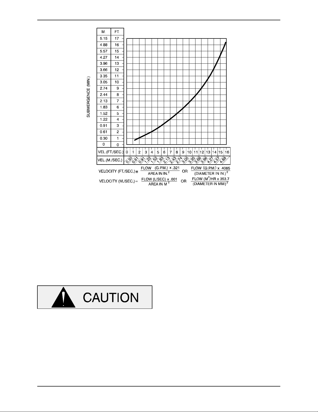
Suction Line Positioning
The depth of submergence of the suction line is
critical to efficient pump operation.
recommended minimum submergence vs. veloc
ity.
Figure 1 shows
Suction Lines In Sumps
If a single suction line is installed in a sump, it
should be positioned away from the wall of the
sump at a distance equal to 1 1/2 times the diame
ter of the suction line.
If there is a liquid flow from an open pipe into the
sump, the flow should be kept away from the suc
NOTE
The pipe submergence required may be reduced
by installing a standard pipe increaser fitting at the
end of the suction line. The larger opening size will
reduce the inlet velocity. Calculate the required
submergence using the following formula based
on the increased opening size (area or diameter).
PAGE B - 3INSTALLATION
OM-06014 ULTRA V SERIES
Figure 1. Recommended Minimum Suction Line Submergence vs. Velocity
DISCHARGE LINES
Siphoning
Do not terminate the discharge line at a level lower
than that of the liquid being pumped unless a si
phon breaker is used in the line. Otherwise, a si
phoning action causing damage to the pump
could result.
Valves
If the application involves a high discharge
head, the discharge throttling valve should
close gradually before the pump is
stopped.
Due to the high discharge head potential
for Ultra V Series pumps, an electronically
controlled or automatic slow‐closing dis
charge throttling valve may be required.
Consult the factory for additional informa
tion on high discharge head applications.
If a throttling valve is desired in the discharge line,
use a valve as large as the largest pipe to minimize
friction losses. Never install a throttling valve in a
suction line.
With high discharge heads, it is recommended that
a throttling valve and a system check valve be in
stalled in the discharge line to protect the pump
from excessive shock pressure and reverse rota
tion when it is stopped.
Bypass Lines
Self‐priming pumps are not air compressors. Dur
ing the priming cycle, air from the suction line must
be vented to atmosphere on the discharge side. If
the discharge line is open, this air will be vented
through the discharge. However, if a check valve
has been installed in the discharge line, the dis
charge side of the pump must be opened to atmos
pheric pressure through a bypass line installed be
tween the pump discharge and the check valve. A
self‐priming centrifugal pump will not prime if
there is sufficient static liquid head to hold the dis
charge check valve closed.
NOTE
The bypass line should be sized so that it does not
PAGE B - 4 INSTALLATION
affect pump discharge capacity; however, the by
pass line should be at least 1 inch in diameter to
minimize the chance of plugging.
In low discharge head applications (less than 30
feet or 9 meters), it is recommended that the by
pass line be run back to the wet well, and located 6
inches below the water level or cut‐off point of the
low level pump. In some installations, this bypass
line may be terminated with a six‐to‐eight foot
length of 1-1/4 inch I.D. smooth‐bore hose; air
and liquid vented during the priming process will
then agitate the hose and break up any solids,
grease, or other substances likely to cause clog
ging.
A bypass line that is returned to a wet well
must be secured against being drawn into
the pump suction inlet.
It is also recommended that pipe unions be in
stalled at each 90 elbow in a bypass line to ease
disassembly and maintenance.
In high discharge head applications (more than
30 feet), an excessive amount of liquid may be by
passed and forced back to the wet well under the
full working pressure of the pump; this will reduce
overall pumping efficiency. Therefore, it is recom
mended that a Gorman‐Rupp Automatic Air Re
lease Valve be installed in the bypass line.
Gorman‐Rupp Automatic Air Release Valves are
reliable, and require minimum maintenance. See
AUTOMATIC AIR RELEASE VALVE in this section
for information about Gorman‐Rupp Automatic Air
Release Valves. Consult your Gorman‐Rupp dis
tributor, or contact the Gorman‐Rupp Company for
selection of an Automatic Air Release Valve to fit
your application.
If the installation involves a flooded suction such as
a below‐ground lift station, a pipe union and manu
al shut‐off valve may be installed in the bleed line to
allow service of the valve without shutting down the
station, and to eliminate the possibility of flooding.
If a manual shut‐off valve is installed anywhere in
the air release piping, it must be a full‐opening ball
type valve to prevent plugging by solids.
OM-06014ULTRA V SERIES
If a manual shut‐off valve is installed in
a bypass line, it must not be left closed
during operation. A closed manual shut‐
off valve may cause a pump which has
lost prime to continue to operate with
out reaching prime, causing dangerous
overheating and possible explosive
rupture of the pump casing. Personnel
could be severely injured.
Allow an over‐heated pump to com
pletely cool before servicing. Do not re
move plates, covers, gauges, or fittings
from an over‐heated pump. Liquid with
in the pump can reach boiling tempera
tures, and vapor pressure within the
pump can cause parts being disen
gaged to be ejected with great force. Af
ter the pump completely cools, drain
the liquid from the pump by removing
the casing drain plug. Use caution when
removing the plug to prevent injury to
personnel from hot liquid.
AUTOMATIC AIR RELEASE VALVE
When properly installed, a Gorman‐Rupp Auto
matic Air Release Valve will permit air to escape
through the bypass line and then close automati
cally when the pump is fully primed and pumping
at full capacity.
Some leakage (1 to 5 gallons [3.8 to 19
liters] per minute) will occur when the
valve is fully closed. Be sure the bypass
line is directed back to the wet well or
tank to prevent hazardous spills.
Consult the manual accompanying the Air Release
Valve for additional information on valve installation
and performance.
PAGE B - 5INSTALLATION
OM-06014 ULTRA V SERIES
Air Release Valve Installation
Staged pump applications generate much higher
operating pressures within the pump casings than
non‐staged pump applications. This high pressure
could cause a suction check valve to fail, resulting
in loss of prime. Therefore, any pump used in a
staged application, whether in the lower or up
per position, must have the suction check valve
removed. The lower stage of the VS Series pump
is designed without a suction check valve, so re
moval of the check valve is not required.
In order to maintain the suction leg and facilitate ini
tial priming (or re‐priming if the suction leg is lost)
without a suction check valve, it is recommended
that staged pump applications be installed using
two discharge check valves, with an automatic Air
Release Valve installed between the two discharge
check valves (see Figure 3). In this manner, when
the liquid level in the sump activates the automatic
liquid level device and starts the pumps, discharge
pressure opens the first discharge check valve, al
lowing any entrained air in the system to escape
through the Air Release Valve. When air in the sys
tem is purged, pressure opens the second dis
charge check valve for full operation.
When the liquid level in the sump lowers enough to
de‐activate the automatic liquid level device and
stop the pumps, the first discharge check valve
closes and creates an air‐tight seal, thus maintain
ing liquid in the pump casing and suction line to al
low the pump to re‐prime when the liquid level in
the sump rises and again activates the automatic
liquid level device.
The second discharge check valve in the staged
application acts as a “shock absorber” to prevent
destructive “water hammer” when the pump shuts
down.
The Automatic Air Release Valve must be inde
pendently mounted in a horizontal position be
tween the discharge check valves. (see Figure 2).
The inlet opening in the Air Release Valve is
equipped with standard 1‐inch NPT pipe threads.
DISCHARGE
PIPE
Figure 2. Typical Automatic Air Release Valve Installation
DISCHARGE
CHECK
VALVE
AIR RELEASE
VALVE
DISCHARGE
CHECK
VALVE
VS SERIES PUMP
NOTE
When installing the Air Release Valve on a staged
pump application, position the Air Release Valve as
PAGE B - 6 INSTALLATION
close as possible to the primary discharge check
valve. Six‐inch and larger discharge check valves
are available drilled and tapped to receive a stan
OM-06014ULTRA V SERIES
dard 1‐inch NPT fitting, or the Air Release Valve may
be installed in a spool flange between the two dis
charge check valves.
Connect the valve outlet to a bleed line which
slopes back to the wet well or sump. The bleed line
must be the same size as the outlet opening or
larger, depending on which Air Release Valve is be
ing used. If piping is used for the bleed line, avoid
the use of elbows whenever possible.
NOTE
For multiple pump installations, it is recommended
that each Air Release Valve be fitted with an inde
pendent bleeder line directed back to the wet well.
If multiple Air Release Valves are installed in a sys
tem, do not direct bleeder lines to a common mani
fold pipe. Contact your Gorman‐Rupp distributor or
the Gorman‐Rupp Company for information about
installation of an Automatic Air Release Valve for
your specific application.
stage pump motor “ramping down” and shutting
off. This “ramp up” and “ramp down” configuration
helps reduce inrush current on startup and de
structive “water hammer” on both startup and shut
down.
DRIVE ARRANGEMENTS
Special consideration must be given to drive ar
rangements for staged pumping applications.
Since pump installations are seldom identical, this
section provides some general recommendations
for selecting drive arrangements for staged
pumps. Consult the factory for information regard
ing your specific application.
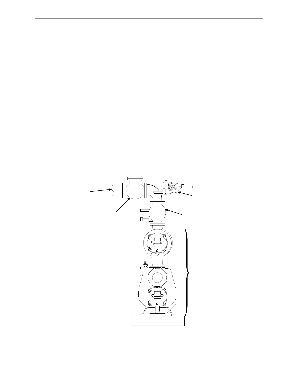
Dual Motor Drives
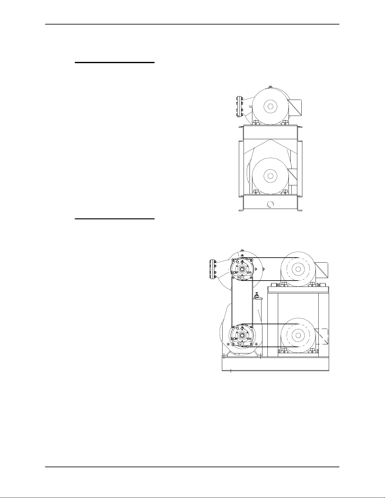
It is recommended that each pump be directly driv
en by its own electric motor, either through cou
plings (see Figure 3) or a belt arrangement (see
Figure 4).
Each motor should be independently operated
through a reduced voltage solid state (RVSS) start
er, a variable frequency drive (VFD) or an adjust
able speed drive (ASD). In this arrangement, the
motor powering the lower stage pump should be
programmed to start first and “ramp up” to full con
dition speed, then the second stage pump motor
should start and “ramp up” to full condition speed.
Pump motor shutdown should be programmed in
reverse order, with the second stage pump motor
“ramping down” before shutting off, then the first
Figure 3. Recommended Dual Motor Direct
Drive Arrangement
Figure 4. Recommended Dual Motor Belt
Drive Arrangement
Single Motor Belt Drives
In staged applications where both pumps are belt
driven by a single motor (either through a syncro
nous [cog] or V‐belt configuration) certain arrange
ments must be used in order to ensure proper op
eration.
PAGE B - 7INSTALLATION
 Loading...