

Page 1
ACU
OM-06520-02
November 11, 2013
INSTALLATION, OPERATION,
AND MAINTENANCE MANUAL
WITH PARTS LIST
SM SERIES PUMPS
THE GORMAN‐RUPP COMPANY D MANSFIELD, OHIO
GORMAN‐RUPP OF CANADA LIMITED D ST. THOMAS, ONTARIO, CANADA Printed in U.S.A.
MODELS
SM3C65-X6
ALL VOLTAGES
www.grpumps.com
e2013 The Gorman‐Rupp Company
Page 2

Register your new
Gorman‐Rupp pump online at
www.grpumps.com
Valid serial number and e‐mail address required.
RECORD YOUR PUMP MODEL AND SERIAL NUMBER
Please record your pump model and serial number in the
spaces provided below. Your Gorman‐Rupp distributor
needs this information when you require parts or service.
Pump Model:
Serial Number:
Page 3

TABLE OF CONTENTS
INTRODUCTION PAGE I - 1.................................................
SAFETY - SECTION A PAGE A - 1...........................................
INSTALLATION - SECTION B PAGE B - 1....................................
RETAINING “PERMISSIBILITY” PAGE B - 1..............................................
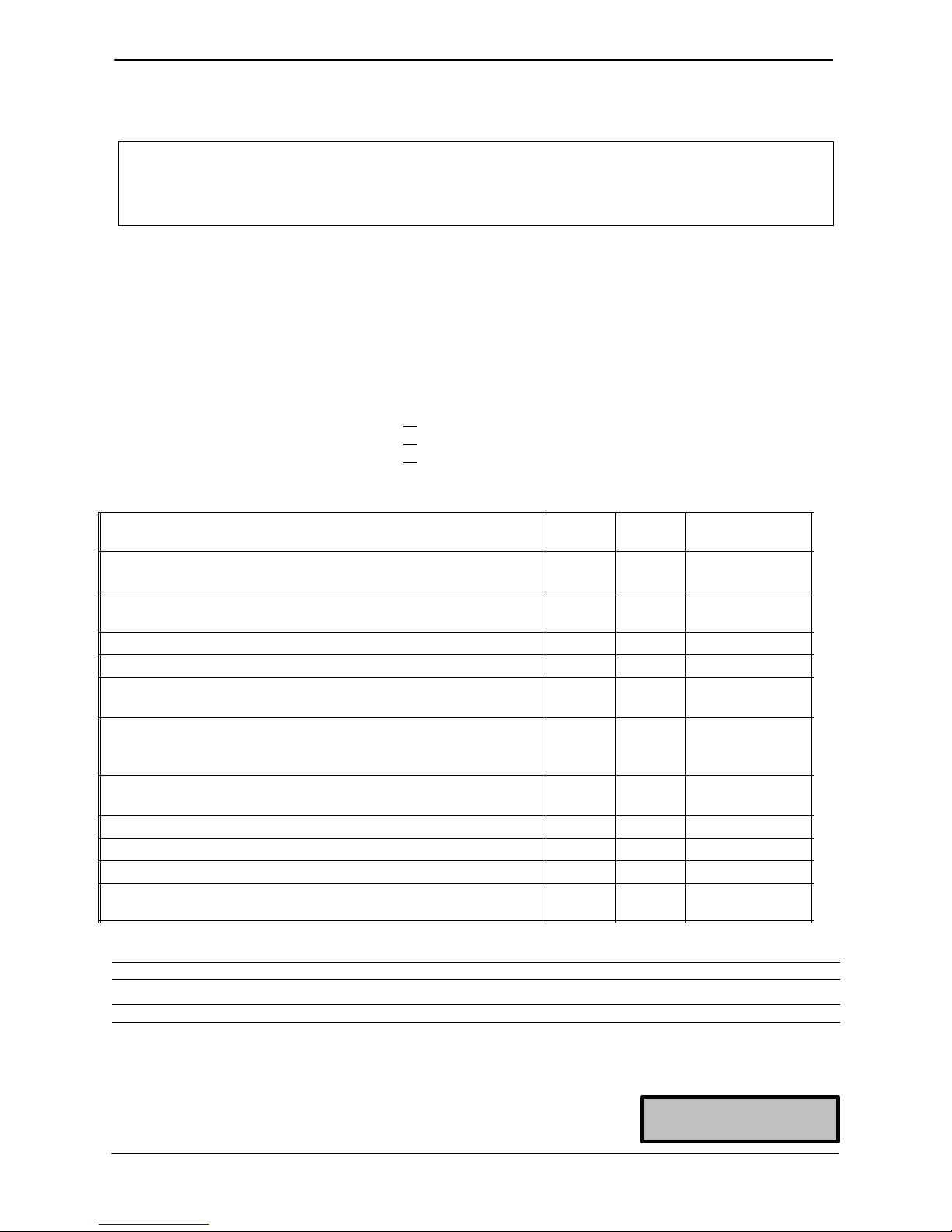
GORMAN‐RUPP MSHA PUMP INSPECTION FORM PAGE B - 2............................
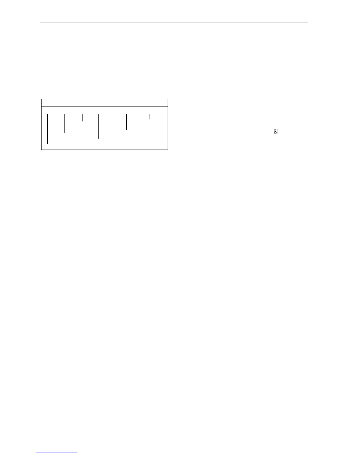
Pump Model Designation PAGE B - 3...............................................
PREINSTALLATION INSPECTION PAGE B - 3............................................
Lubrication PAGE B - 3............................................................
PUMP INSTALLATION PAGE B - 4......................................................
Pump Specifications PAGE B - 4....................................................
Pump Dimensions PAGE B - 4.....................................................
Lifting PAGE B - 5.................................................................
Positioning the Pump PAGE B - 5...................................................
PIPING PAGE B - 6...................................................................
CONTROL BOX PAGE B - 6...........................................................
Enclosure PAGE B - 6.............................................................
Grounding Methods PAGE B - 10....................................................
Field Wiring Connections (Incoming Power) PAGE B - 11...............................
Pump Power Cable Connections PAGE B - 12.........................................
LIQUID LEVEL CONTROL PAGE B - 13..................................................
OPERATION - SECTION C PAGE C - 1......................................
CONTROL BOX FUNCTION PAGE C - 1.................................................
Component Function PAGE C - 1...................................................
PUMP OPERATION PAGE C - 1........................................................
Liquid Temperature And Overheating PAGE C - 2.....................................
Checking Pump Rotation PAGE C - 2...............................................
STARTING PAGE C - 3................................................................
STOPPING PAGE C - 3................................................................
OPERATIONAL CHECKS PAGE C - 4...................................................
COLD WEATHER PRESERVATION PAGE C - 4...........................................
LUBRICATION PAGE C - 4.............................................................
Draining Oil PAGE C - 4...........................................................
Condition of Oil PAGE C - 4........................................................
Adding Oil PAGE C - 4............................................................
TROUBLESHOOTING - SECTION D PAGE D - 1..............................
ELECTRICAL TESTING PAGE D - 2.....................................................
Test Equipment PAGE D - 3........................................................
Voltage Imbalance PAGE D - 3.....................................................
Motor And Motor Power Cable Continuity PAGE D - 3.................................
Insulation Resistance PAGE D - 4...................................................
PUMP MAINTENANCE AND REPAIR - SECTION E PAGE E - 1................
STANDARD PERFORMANCE CURVE PAGE E - 1........................................
PARTS LISTS
Pump Model PAGE E - 3..........................................................
Submersible Motor Assemblies PAGE E - 5..........................................
PUMP END DISASSEMBLY PAGE E - 6.................................................
i
Page 4

TABLE OF CONTENTS
(continued)
Strainer and Suction Head Removal PAGE E - 7......................................
Draining Oil From Seal Cavity PAGE E - 7............................................
Positioning Pump For Disassembly PAGE E - 7.......................................
Impeller Removal PAGE E - 7......................................................
Lower Seal Removal PAGE E - 7....................................................
Upper Seal Removal PAGE E - 8...................................................
PUMP END REASSEMBLY PAGE E - 8..................................................
Cleaning And Inspection Of Pump Parts PAGE E - 8..................................
Upper Seal Installation PAGE E - 9..................................................
Seal Plate Installation PAGE E - 10...................................................
Lower Seal Installation PAGE E - 11..................................................
Impeller Installation PAGE E - 12.....................................................
Strainer Installation PAGE E - 12.....................................................
MOTOR DISASSEMBLY PAGE E - 12....................................................
Terminal Housing And Power Cable Removal And Disassembly PAGE E - 13..............
Shaft and Rotor Removal PAGE E - 13...............................................
Stator Removal PAGE E - 14........................................................
MOTOR REASSEMBLY PAGE E - 14.....................................................
Stator Installation PAGE E - 15......................................................
Shaft And Rotor Installation PAGE E - 15.............................................
Terminal Housing And Power Cable Reassembly And Installation PAGE E - 16............
FINAL ASSEMBLY PAGE E - 18.........................................................
LUBRICATION PAGE E - 18.............................................................
Seal Cavity PAGE E - 18............................................................
Pump Oil Specifications PAGE E - 19.................................................
Motor Bearings PAGE E - 19........................................................
ii
Page 5
SM SERIES
OM-06520
INTRODUCTION
Thank You for purchasing a Gorman‐Rupp pump.
Read this manual carefully to learn how to safely
install and operate your pump. Failure to do so
could result in personal injury or damage to the
pump.
This pump is an S Series model. The basic material
of construction is CD4MCu stainless steel, with 316
stainless steel rotor shaft, motor housing and hard
ware. The pump is designed to handle industrial
chemical and low pH resistance materials. The in
tegral electric motor must be operated through the
control box furnished with the pump as standard
equipment. The pump and control comply with
MSHA schedule 2G regulations, and have been
approved for use in hazardous locations by the
Pennsylvania Department of Environmental Re
sources (D.O.E.R.).
This manual will alert personnel to known proce
dures which require special attention, to those
which could damage equipment, and to those
which could be dangerous to personnel. However,
this manual cannot possibly anticipate and provide
detailed precautions for every situation that might
occur during maintenance of the unit. Therefore, it
is the responsibility of the owner/maintenance per
sonnel to ensure that only safe, established main
tenance procedures are used, and that any proce
dures not addressed in this manual are performed
only after establishing that neither personal safety
nor pump integrity are compromised by such prac
tices.
The following are used to alert maintenance per
sonnel to procedures which require special atten
tion, to those which could damage equipment, and
to those which could be dangerous to personnel:
Immediate hazards which WILL result in
severe personal injury or death. These
instructions describe the procedure re
quired and the injury which will result
from failure to follow the procedure.
Hazards or unsafe practices which
COULD result in severe personal injury
or death. These instructions describe
the procedure required and the injury
which could result from failure to follow
the procedure.
If there are any questions regarding the pump or
its application which are not covered in this man
ual or in other literature accompanying this unit,
please contact your Gorman Rupp distributor, or
The Gorman‐Rupp Company:
The Gorman‐Rupp Company
P.O. Box 1217
Mansfield, Ohio 44901-1217
Phone: (419) 755-1011
or:
Gorman‐Rupp of Canada Limited
70 Burwell Road
St. Thomas, Ontario N5P 3R7
Phone: (519) 631-2870
Hazards or unsafe practices which COULD
result in minor personal injury or product
or property damage. These instructions
describe the requirements and the possi
ble damage which could result from failure
to follow the procedure.
NOTE
Instructions to aid in installation, operation, and
maintenance or which clarify a procedure.
PAGE I - 1INTRODUCTION
Page 6
SM SERIES
OM-06520
SAFETY - SECTION A
This information applies to SM Series
submersible motor driven pumps.
Because pump installations are seldom
identical, this manual cannot possibly
provide detailed instructions and pre
cautions for each specific application.
Therefore, it is the owner/installer's re
sponsibility to ensure that applications
not addressed in this manual are per
formed only after establishing that nei
ther operator safety nor pump integrity
are compromised by the installation.
Before attempting to open or service the
pump:
1. Familiarize yourself with this man
ual.
2. Lock out incoming power to the
control box to ensure that the
pump will remain inoperative.
3. Allow the pump to completely cool
if overheated.
4. Close the discharge valve (if
used).
The pump is designed to be operated
through the control box furnished with
the pump. The control box provides
overload protection and power control.
Do not connect the pump motor directly
to the incoming power lines.
alified electrician to make all electrical
connections. Make certain that the
pump and enclosure are properly
grounded. Be sure that the incoming
power matches the voltage and phase
of the pump and control before connect
ing the power source. Do not run the
pump if the voltage is not within the lim
its.
The electrical power used to operate
this pump is high enough to cause inju
ry or death. Make certain that the control
handle on the control box is in the off po
sition and locked out, or that the power
supply to the control box has been
otherwise cut off and locked out, before
attempting to open or service the pump
assembly. Tag electrical circuits to pre
vent accidental start up.
All electrical connections must be in ac
cordance with MSHA Schedule 2G. If
there is a conflict between the instruc
tions provided and MSHA specifica
tions, MSHA specifications shall take
precedence. All electrical equipment
supplied with this pump was in confor
mance with MSHA requirements in ef
fect on the date of manufacture. Failure
to follow applicable specifications, or
substitution of electrical parts not
supplied or approved by the manufac
turer, can result in severe injury or
death.
The electrical power used to operate
this pump is high enough to cause inju
ry or death. Obtain the services of a qu
This pump is not designed to pump vol
PAGE A - 1SAFETY
Page 7
atile, explosive, or flammable materials.
Refer to the chart in Installation, Section
B for the basic materials of construction
for each pump covered in this manual.
Do not
attempt to pump any liquids for
which your pump is not approved, or
which may damage the pump or endan
ger personnel as a result of pump fail
ure. Consult the factory for specific
application data.
Death or serious personal injury and
damage to the pump or components
can occur if proper lifting procedures
are not observed. Make certain that
hoists, chains, slings or cables are in
good working condition and of suffi
cient capacity and that they are posi
tioned so that loads will be balanced
and the pump or components will not be
damaged when lifting. Do not attempt to
lift this pump by the motor or control
cables, or the piping. Attach proper lift
ing equipment to the lifting bail fitted on
the pump. Lift the pump or component
only as high as necessary and keep per
sonnel away from suspended objects.
SM SERIESOM-06520
After the pump has been installed, make
certain that the pump and all piping or
hose connections are secure before op
eration.
Approach the pump cautiously after it
has been running. Although the motor is
cooled by the liquid being pumped, nor
mal operating temperatures can be high
enough to cause burns. The tempera
ture will be especially high if operated
against a closed discharge valve. Never
operate against a closed discharge
valve for long periods of time.
Do not open the control box in an explo
sive atmosphere. When sealed, the con
trol box is explosion proof to prevent the
ignition of combustible gases. Opening
the box in an explosive atmosphere
could result in fire or explosion.
PAGE A - 2 SAFETY
Page 8
INSTALLATION - SECTION B
OM-06520SM SERIES
Review all SAFETY information in Section A.
This section is intended only to summarize recom
mended installation practices for the pump and
control box. If there are any questions concerning
your specific application, contact your Gor
man‐Rupp distributor or the Gorman‐Rupp Com
pany
All functions performed by the customer on the
pump or control must be done in accordance with
MSHA schedule 2G regulations to ensure the ex
plosion‐proof integrity. No alterations of original
design may be made without the consent of the
Gorman‐Rupp Company and MSHA.
To retain “Permissibility” of this equipment,
the following conditions shall be satisfied:
1. GENERAL SAFETY. FREQUENT INSPECTION
SHALL BE MADE. ALL ELECTRICAL PARTS,
INCLUDING THE PORTABLE CABLE AND WIR
ING, SHALL BE KEPT IN A SAFE CONDITION.
THERE SHALL BE NO OPENINGS INTO THE
CASINGS OF THE ELECTRICAL PARTS. A
PERMISSIBLE DISTRIBUTION BOX SHALL BE
USED FOR CONNECTION TO THE POWER
CIRCUIT UNLESS CONNECTION IS MADE IN
FRESH INTAKE AIR. THE MACHINE FRAME
SHALL BE EFFECTIVELY GROUNDED. THE
POWER WIRES SHALL NOT BE USED FOR
GROUNDING. THE OPERATING VOLTAGE
MUST MATCH THE VOLTAGE RATING OF THE
MOTOR(S) 10%.
2. SERVICING. EXPLOSION PROOF ENCLO
SURES SHALL BE RESTORED TO THE STATE
OF ORIGINAL SAFETY WITH RESPECT TO ALL
FLAME ARRESTING PATHS, LEAD EN
TRANCES, ETC., FOLLOWING DISASSEMBLY
FOR REPAIR OR REBUILDING, WHETHER BY
THE OWNER OR AN INDEPENDENT SHOP.
3. FASTENING. ALL BOLTS, NUTS, SCREWS,
AND OTHER MEANS OF FASTENING, AND
ALSO THREADED COVERS, SHALL BE IN
PLACE, PROPERLY TIGHTENED AND SE
CURED.
4. RENEWALS AND REPAIRS. INSPECTIONS,
REPAIRS, OR RENEWALS OF ELECTRICAL
PARTS SHALL NOT BE MADE UNLESS THE
PORTABLE CABLE IS DISCONNECTED FROM
THE CIRCUIT FURNISHING POWER, AND THE
CABLE SHALL NOT BE CONNECTED AGAIN
UNTIL ALL PARTS ARE PROPERLY REASSEM
BLED. SPECIAL CARE SHALL BE TAKEN IN
MAKING RENEWALS OR REPAIRS. LEAVE NO
PARTS OFF. USE REPLACEMENT PARTS EX
ACTLY LIKE THOSE FURNISHED BY THE
MANUFACTURER. WHEN ANY LEAD EN
TRANCE IS DISTURBED, THE ORIGINAL
LEADS OR EXACT DUPLICATES THEREOF
SHALL BE USED AND STUFFING BOXES
SHALL BE REPACKED IN THE APPROVED
MANNER.
5. CABLE REQUIREMENTS. A FLAME RESIS
TANT PORTABLE CABLE BEARING A MSHA
ASSIGNED IDENTIFICATION NUMBER, ADE
QUATELY PROTECTED BY AN AUTOMATIC
CIRCUIT INTERRUPTING DEVICE, SHALL BE
USED. SPECIAL CARE SHALL BE TAKEN IN
HANDLING THE CABLE TO GUARD AGAINST
MECHANICAL INJURY AND WEAR. SPLICES
IN PORTABLE CABLES SHALL BE MADE IN A
WORKMANLIKE MANNER, MECHANICALLY
STRONG, AND WELL INSULATED. ONE TEM
PORARY SPLICE MAY BE MADE IN ANY TRAIL
ING CABLE. SUCH TRAILING CABLE MAY
ONLY BE USED FOR THE NEXT 24 HOUR PE
RIOD. NO TEMPORARY SPLICE SHALL BE
MADE IN A TRAILING CABLE WITHIN 25 FEET
OF THE MACHINE, EXCEPT CABLE REEL
EQUIPMENT. CONNECTIONS AND WIRING
TO THE OUTBY END OF THE CABLE SHALL
BE IN ACCORDANCE WITH RECOGNIZED
STANDARDS OF SAFETY.
PAGE B - 1INSTALLATION
Page 9
OM-06520 SM SERIES
GORMAN-RUPP MSHA PUMP INSPECTION FORM
INSPECTOR____________________________ DATE____________
MODEL NO.____________________________ SERIAL NO.____________
UNIT ELECTRICAL RATING:
H.P.________, VOLTS________, PUMP AMPS________, HERTZ________
STARTER X/P NO: XP3026-1 (CONTROL WITHOUT FLOAT)
OR
18-XPA040007-0 (CONTROL WITH FLOAT)
MOTOR CABLE:
___No. 12; 7 Conductor; Type SPC; .89 + .03 O.D.; Heavy Jacketed; Royal – MSHA 122;
___No. 8; 9 Conductor; Type SPC; 1.05 + .03 O.D.; Heavy Jacketed; Royal – MSHA 122;
___No. 6; 9 Conductor; Type SPC; 1.25 + .04 O.D.; Heavy Jacketed, Royal – MSHA 122;
Length______________________
ITEM AREA OF INSPECTION ACC. REJ. CORRECTED
1. Are lock washers (or equivalent) provided for all ex
plosion proof enclosure fastenings?
2. Are all plane joints securely fastened so that a
.005-inch feeler gauge cannot be inserted?
3. Is motor plug secured with lock clip?
4. Are all electrical connections secure?
5. Are all electrical connections insulated where neces
sary and per appropriate drawing?
6. Are packing glands properly packed so that
1/8-inch clearance remains between packaging nut
and stuffing box?
7. Are packing nut and cable grip secured with lock
wire and lead seal?
8. Was pump leak tested?
9. Was pump and control electrically tested?
10. Was pump water tested?
11. Are pump, cable, and control assembled together
properly per appropriate drawing?
Comments:
NOTE: Fill out form completely and “rejections” must be corrected and re-inspected. Inspec
tor must initial and date when corrective action was taken. 10/9/87
Form CD GL-02128 Rev 6/05
Doc# 152708
PAGE B - 2 INSTALLATION
This form not to be revised
without approval of MSHA.
Page 10
OM-06520SM SERIES
Pump Model Designation
Following is a description of the model numbering
system for SM Series pumps. These submersible
pumps are available in a range of sizes. Refer to the
following chart to identify the size for your specific
pump model.
Pump Model
SM
Series
3 C 1 460/3- X6
Pump
Hydraulics
Discharge
Size
Pump
Construction
Voltage/Phase
H.P.
(If Shown)
Review all SAFETY information in Section A.
This section is intended only to summarize recom
mended installation practices for the pump and
control box. If there are any questions concerning
your specific application, contact your Gor
man‐Rupp distributor or the Gorman‐Rupp Com
pany.
PREINSTALLATION INSPECTION
and that the electrical connections are tight
and free of corrosion.
f. Compare the amperes, phase, voltage and
hertz indicated on the motor nameplate to the
ratings indicated for the control box.
g. Carefully read all tags, decals, and markings
on the pump assembly and the control box,
and perform all duties as indicated.
h. Check the pump and motor for any oil leaks.
An oil leak may indicate a cut O ring or other
damage.
i. If the pump and control box have been stored
for more than 12 months, some of the compo
nents or lubricants may have exceeded their
maximum shelf life. These must be inspected
or replaced to ensure maximum pump serv
ice.
If the maximum shelf life has been exceeded, or if
anything appears to be abnormal, contact your
Gorman‐Rupp distributor or the factory to deter
mine the repair or updating policy. Do not put the
pump into service until appropriate action has
been taken.
The pump and control box were inspected and
tested before shipment from the factory. Before in
stallation, inspect the pump for damage which may
have occurred during shipment. Check as follows:
a. Inspect the pump assembly for cracks, dents,
damaged threads, and other obvious dam
age.
b. Check for and tighten loose attaching hard
ware. Since gaskets tend to shrink after dry
ing, check for loose hardware at mating sur
faces.
c. The standard pump is furnished with 50 feet
(15,2 m) of power cable. Inspect the cable for
cuts or damage.
d. Inspect the control box for cracks, dents, and
other obvious damage.
e. Check that all control box components are se
curely attached to their mounting surfaces,
Lubrication
This pump series utilizes one lubrication cavity, lo
cated just behind the seal plate. It is filled with pre
mium quality submersible pump oil which lubri
cates two shaft seals. The motor operates in air
and requires no lubrication.
The lower shaft seal prevents liquid from entering
the lubrication cavity, while the upper shaft seal
prevents oil leakage into the motor. The upper seal
also acts as backup protection in the event of lower
seal failure.
The lubrication cavity was fully lubricated when
shipped from the factory. Check the oil level before
installing the pump (see LUBRICATION in MAIN
TENANCE AND REPAIR). An additional quart of
oil has been provided with the pump to “top off” the
oil cavity. If the oil level is abnormally low, deter
mine the cause before putting the pump into serv
ice.
PAGE B - 3INSTALLATION
Page 11
OM-06520 SM SERIES
PUMP INSTALLATION
Pump Specifications
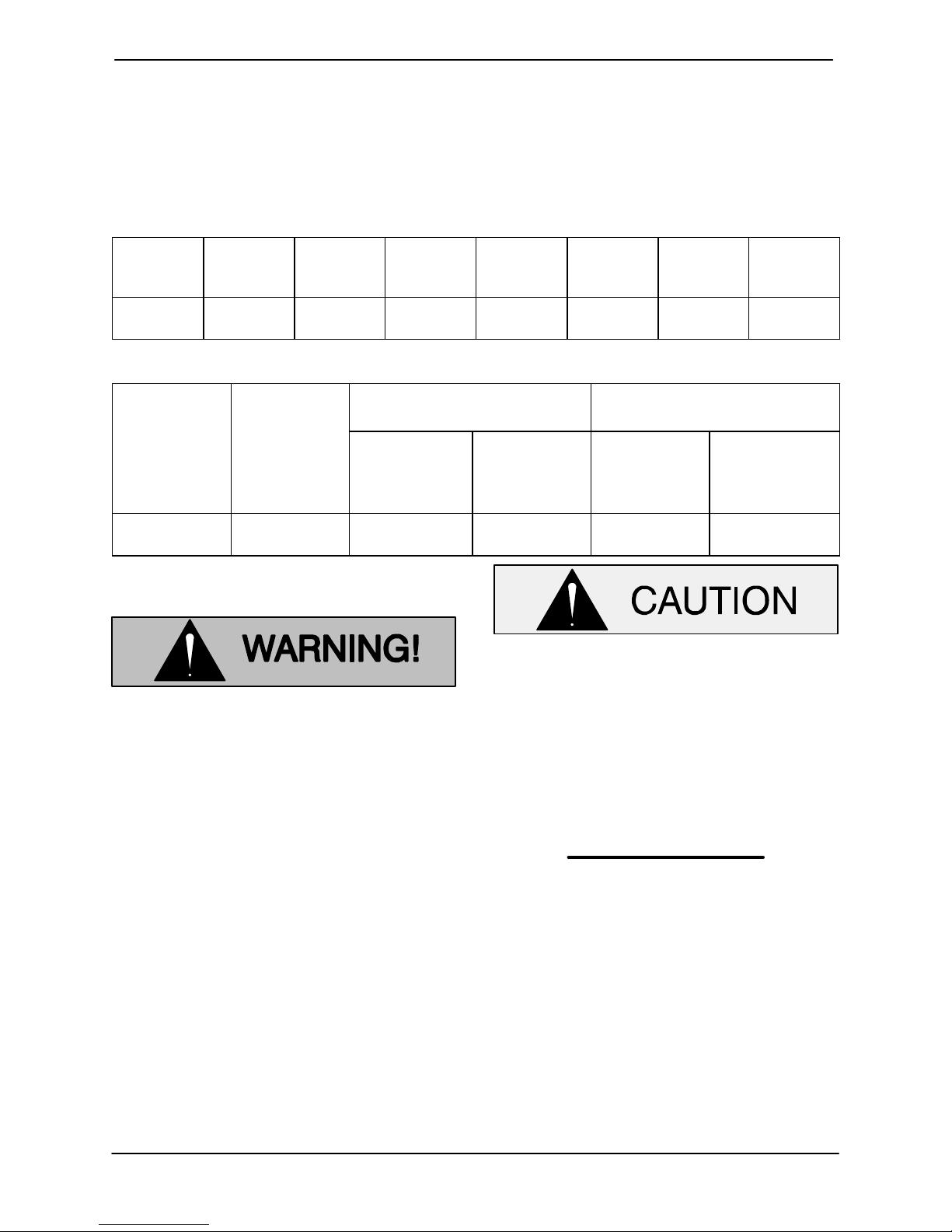
See Tables B-1 and B-2 for pump specifications.
Table B-1. Pump Specifications
Voltage/
Model
SM3C 460/3
Pump
Model
Phase
575/3
Motor
Horse
power
60 3450 10.8
Table B-2. Additional Specifications
Voltage/
Phase
Pump
Speed
(RPM)
Approximate Weight
Lbs. (kg) Seal Cavity
Pump 50Ft. Cable
Full
Load
Amperes
8.6
No
Load
Amperes
4.0
3.2
Oil Capacity
Ounces
(Liters)
Locked
Rotor
Amperes
56
45
Filling Position
Discharge
Size
(NPT)
3 INCH
(H)orizontal
(V)ertical
SM3C 460/3
575/3
Pump Dimensions
105 (47,6) 23 (10,4) 16 (0,47) H
When installing or servicing the pump
or controls, follow all requirements for
the installation of wiring or electrical
equipment as outlined in the National
Electric Code. Follow all MSHA safety
requirements. Failure to observe these
requirements could result in injury or
death to personnel.
Do not allow the free end of the power
cable to enter the liquid being pumped.
The free end of the cable must be kept dry
to prevent liquid from wicking through the
cable and into the motor.
NOTE
Refer to the performance curve in Section E, MAIN
TENANCE AND REPAIR when determining the
most efficient piping installation.
PAGE B - 4 INSTALLATION
Page 12
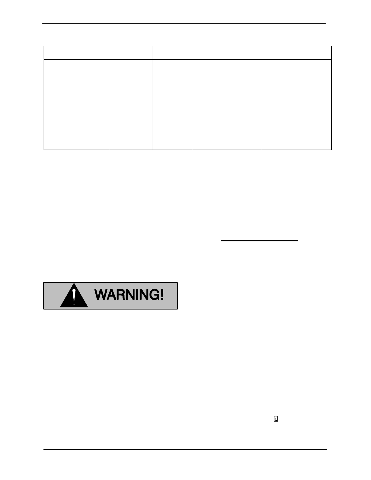
Table B-3. MSHA Specifications And Approval Data
OM-06520SM SERIES
Model No.
SM3C65‐X6 460/3
SM3C65‐X6 575/3
Lifting
Pump unit weights can vary depending on the ma
terial of construction and length of cable on the
unit. Check the shipping tag on the unit packaging
for the actual weight, and use lifting equipment
with appropriate capacity. Remove all customer‐
installed equipment such as suction and dis
charge hoses or piping before attempting to lift ex
isting, installed units.
MSHA No Cable P/N Trailing Cable Motor Cable
XP-3185-1
XP-3185-1
47351-011
47351-011
No. 8, 3 Conductor,
Type G‐GC, 0.97” $
.03” O.D., Protected By
An Instantaneous Trip
Circuit Breaker, Set At
200 Amps Max. MSHA
Flame Resistance,
600/2000 Volt, 90_C.
Max. Length: 500 Ft. ‐
Customer Furnished
Note: Instantaneous
Trip Amps Set At 200
Amps Max.
Positioning the Pump
G‐R P/N 47351-011.
#12 AWG., 7 Conductor
Type SPC, 0.89” "
0.03” O.D., Yellow Jack
et. 90_C 600/2000 Volt
Royal ‐ MSHA Flame
Resistant, Max. Cable
Length: - Combined
Trailing Cable And
Pump Motor Cable Not
To Exceed 500 Ft.
NOTE
Before installing and operating the pump, check
the direction of impeller rotation to ensure that the
pump is properly wired at the control box. See IM
PELLER ROTATION, Section C.
Refer to Table B-2 for the approximate maximum
weight for each pump.
Death or serious personal injury and
damage to the pump or components
can occur if proper lifting procedures
are not observed. Make certain that
hoists, chains, slings or cables are in
good working condition and of suffi
cient capacity and that they are posi
tioned so that loads will be balanced
and the pump or components will not be
damaged when lifting. Do not attempt to
lift this pump by the motor or control
cables, or the piping. Attach proper lift
ing equipment to the lifting bail fitted on
the pump. Lift the pump or component
only as high as necessary and keep per
sonnel away from suspended objects.
This pump is designed to operate fully or partially
submerged. It may also be operated in air for ex
tended periods. The rotating parts are oil lubri
cated, and the motor is cooled by a constant flow of
liquid or air discharged through internal passages.
The pump will operate if positioned on its side, but
this is not recommended because the motor
torque could cause the pump to roll during opera
tion.
The pump should be independently secured and
supported by the lifting device fitted on the pump. If
the application involves a lot of debris, protect the
pump from excessive wear and clogging by sus
pending it in a perforated barrel or culvert pipe. If
the bottom is heavily sludge covered, rest the
pump on support blocks or suspend it from a raft or
similar device near the surface of the liquid. See
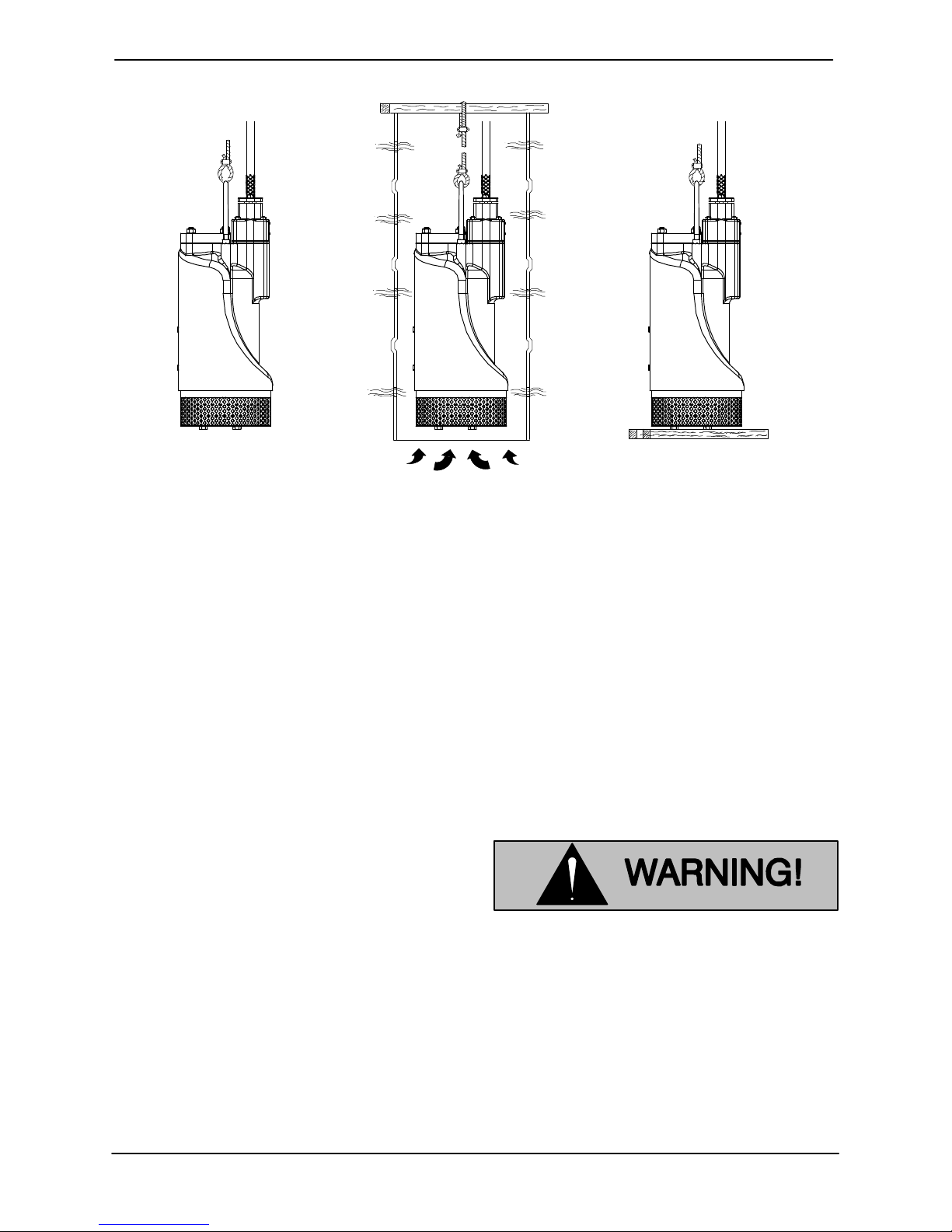
Figure B-1 for typical pump installations.
PAGE B - 5INSTALLATION
Page 13
OM-06520 SM SERIES
BY BAIL IN PERFORATED CULVERT PIPE ON SUPPORTS
Figure B-1. Typical Pump Installations
All liquid entering the pump must pass through a
strainer screen. Any spherical solids which pass
through the screen will pass through the pump.
PIPING
No suction piping is required in a standard sub
merged application.
SM Series pumps are provided with a suction
strainer to prevent large solids from clogging the
impeller. On high discharge head applications, the
strainer can be removed, and the pump suction
“staged” to the discharge of another pump, allow
ing one pump to feed the other.
To determine the size of the discharge connection,
see Table B-1, Pump Specifications. Either
hose or rigid pipe may be used. To facilitate mobil
ity and maintenance, it is recommended that the
discharge line be fitted with a quick disconnect fit
ting near the pump. The discharge line must be in
dependently supported to avoid strain and vibra
tion on the pump.
the use of elbows and fittings which increase fric
tion losses through the discharge piping system.
It is recommended that a check valve or throttling
valve be installed in the discharge line to control si
phoning or back flow when the pump is shut off.
CONTROL BOX
This pump is driven by an integral 60 hertz, 6 HP
motor. It is designed to operate through the control
box furnished with the pump.
The pump motor is designed to be oper
ated through the control box furnished
with the pump. The control box provides
overload protection and power control.
Do not connect the pump motor directly
to the incoming power lines.
Enclosure
For maximum pumping capacity, keep the dis
charge as short and straight as possible. Minimize
PAGE B - 6 INSTALLATION
The control box is a NEMA type 10, MSHA certified
enclosure. The enclosure is not designed to be
Page 14
OM-06520SM SERIES
watertight, and should not be submerged. See
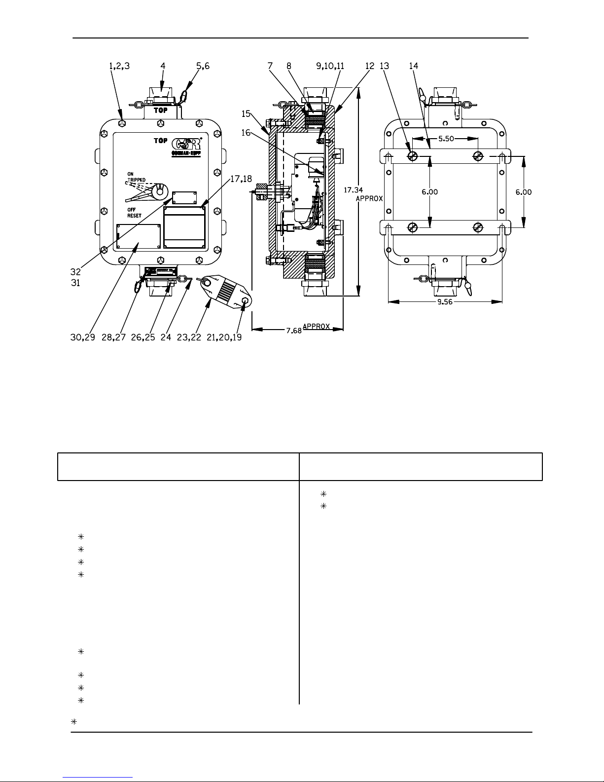
Figure B-2 for enclosure dimensions and callouts.
Secure the control box vertically on a level surface,
above flood level. The box should be easily acces
sible to the operator, and located close enough to
the pump to avoid excessive voltage drop due to
cable length (see Pump Power Cable Connec
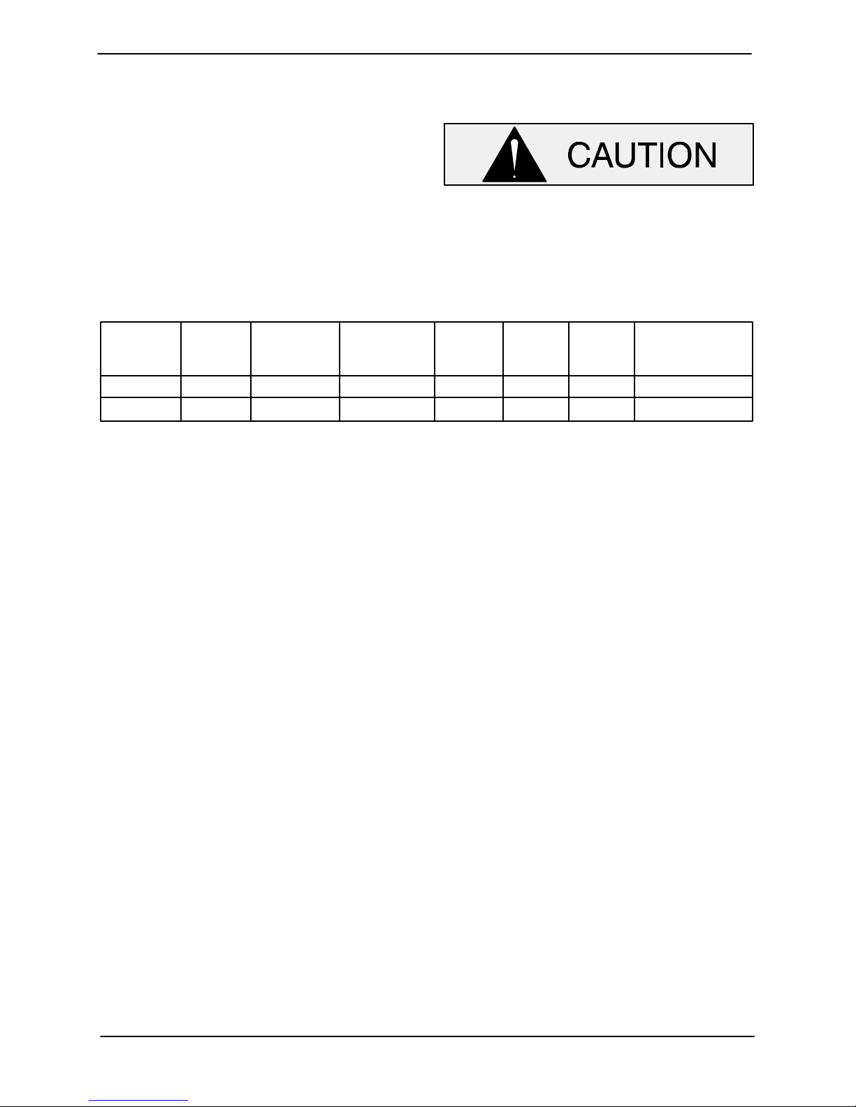
Table B-4. Control Box Specifications
Model Voltage/ Control Box
Phase
SM3C 460/3 13.0 14.3 17.6 XP-3185-1
SM3C 575/3 10.4 14.3
Part No.
47631-148
47631-149
Mtg. Plate
Part No.
47882-005
47882-006 XP-3185-111.4
tions). After the box is installed, make certain the
front cover latches properly.
Failure to mount the control box vertically
on a level surface may affect operation of
the pump controls.
Relay
Rating
(Amps)
Hold
Amps
Trip
Amps
MSHA
Cert. No.
PAGE B - 7INSTALLATION
Page 15
OM-06520 SM SERIES
Figure B-2. Control Box Assembly
PARTS LIST - EXTERNAL PARTS
47631-148 (460V) AND 47631-149 (575V) CONTROL BOXES
(See Figure 3 For Internal Control Box Parts)
ITEM
PART NAME PART
NO.
1 HEX HD CAPSCREW 21632-597 ----- 14
2 LOCKWASHER J06 15991 14
3 FLAT WASHER KE06 15991 14
4 PACKING GLAND NUT 31874-017 13045 2
5 LEAD SEAL 21188-002 ----- 2
6 WIRE - 14 INCH 31311-004 17990 2
7 ROPE PACKING 31313-010 22120 1
8 PACKING WASHER 31133-109 13150 4
9 GROUND LUG 27222-004 ----- 2
10 HEX HD CAPSCREW B0402 15991 4
11 LOCKWASHER J04 15991 4
12 ENCLOSURE 38383-001 13045 1
13 FL HD MACH SCREW Y0602 15991 4
14 MOUNTING BRACKET 33657-002 13090 2
15 ENCL COVER ASSY 42114-074 ----- 1
-ENCLOSURE COVER 38383-401 13015 1
-ON/OFF HANDLE 38421-012 13040 1
-HANDLE SETSCREW GA0501 1/2 15990 1
-SHAFT ASSY 41881-276 24150 1
NUMBER
MAT'L
CODE
QTY ITEM
NO.
PART NAME PART
NUMBER
-SHAFT BUSHING 31513-031 13155 1
-BUSHING SETSCREW GA#10-01S 15990 1
-WIRING DECAL 2613GM ----- 1
16 MTG PLT ASSY (460V) 47882-005 ----- 1
MTG PLT ASSY (575V) 47882-006 ----- 1
17 MSHA CERT PLATE 2613GL 17020 1
18 DRIVE SCREW BM#04-03 17000 4
19 HEX HD CAPSCREW B0608 15991 4
20 LOCKWASHER J06 15991 4
21 HEX NUT D06 15991 4
22 CABLE CLAMP 38116-603 13040 4
23 RUB BRKT PROTECTOR 33573-001 19990 4
24 CHAIN - 3/16 X 12 41158-009 15991 2
25 HEX HD CAPSCREW B0604 15991 2
26 LOCKWASHER J06 15991 2
27 ASSEMBLY PLATE 2613GG 17020 1
28 DRIVE SCREW BM#04-03 17000 2
29 MSHA APPROVAL PLATE 2613ES 17020 1
30 DRIVE SCREW BM#04-03 17000 2
31 PENN DOER APPL PLATE 2613FL 17020 1
32 DRIVE SCREW BM#04-03 17000 4
MAT'L
CODE
QTY
INDICATES PARTS RECOMMENDED FOR STOCK
PAGE B - 8 INSTALLATION
Page 16
OM-06520SM SERIES
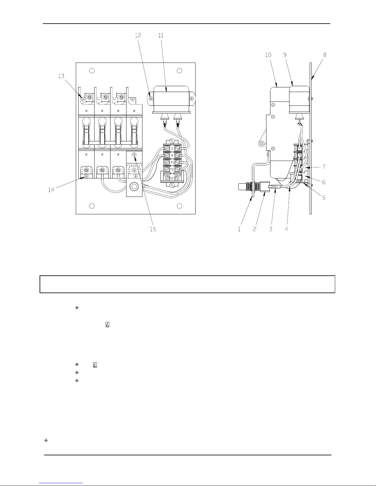
Figure B-3. Electrical Mounting Plate Assembly
PARTS LIST
47882-005 (460V) AND 47882-006 (575V) MOUNTING PLATE ASSEMBLIES
(See Figure 2 For External Control Box Parts)
ITEM
NO.
PART NAME
PART
NUMBER
MAT'L
CODE
1 SWITCH BRACKET 34512-027 ----- 1
2 CUTLER HAMMER SWITCH 27341-211 ----- 1
3 TERMINAL S1790 ----- 2
4 WIRE 14 GA. X 36.5 IN. LG. 38746-027 ----- 1
5 TERMINAL BLOCK END 27233-021 ----- 1
6 TERMINAL BLOCK NOT REQUIRED ----7 TERMINAL BLOCK 27233-203 ----- 5
8 MOUNTING PLATE 33287-011 ----- 1
9 G E CAPACITOR 27571-332 ----- 1
10 RELAY/SHUNT TRIP (460V) 27541-483 ----- 1
RELAY/SHUNT TRIP (575V) 27541-495 ----- 1
11 CAPACITOR BRACKET 27581-904 ----- 1
12 RD PHILLIP MACH SCREW 21771-551 ----- 2
13 RD PHILLIP MACH SCREW 21771-552 ----- 4
14 RD PHILLIP MACH SCREW 21771-553 ----- 2
15 RD PHILLIP MACH SCREW 21771-542 ----- 1
QTY
INDICATES PARTS RECOMMENDED FOR STOCK
PAGE B - 9INSTALLATION
Page 17
OM-06520 SM SERIES
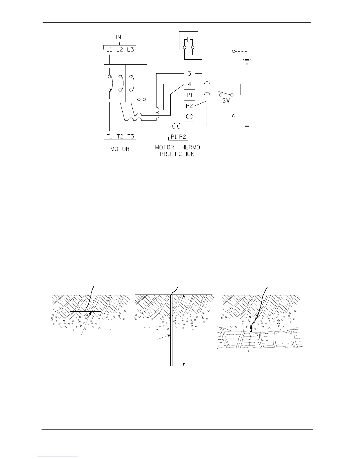
Figure B-4. Mounting Plate Wiring Schematic
Grounding Methods
Electrically ground the installation before before
connecting the field wiring to the control box. Install
a grounding terminal to the enclosure and connect
it to a properly embedded electrode.
The material used for the electrode must be an ex
cellent conductor of electricity, such as copper. If
iron or steel is used, it must be galvanized or other
a) PLATE ELECTRODE b) DRIVEN ELECTRODE c) BURIED ELECTRODE
SOIL
1/4 INCH (6,4 MM)
STEEL PLATE 2 SQ.
FEET (1858,1 SQ. CM)
SURFACE AREA
(MINIMUM)
SOIL
3/4 INCH (19,1
MM) NOMINAL
DIAMETER
(MINIMUM)
wise metal plated to resist corrosion. Do not coat
the electrode with any material of poor conductiv
ity, such as paint or plastic.
The electrode must conform to the recommenda
tions of N.E.C. ARTICLE 250. Follow all installation
requirements of the N.E.C., and all applicable
codes. See Figure B-5 for some suggested
grounding methods.
SOIL
8
ROCK
FEET
(2,4
M)
3/4 INCH (19,1 MM)
NOMINAL DIAMETER
(MINIMUM) 8 FEET
(2,4 M) LONG
Figure B-5. Suggested Grounding Methods
a. Plate Electrode: An iron or steel plate, 1/4
inch (6,4 mm) thick, completely impeded in
the ground. The plate must present a surface
area of at least 2 square feet (1858,1 sq. cm).
PAGE B - 10 INSTALLATION
b. Driven Electrode: A rod or pipe, 3/4 inch
(19,1 mm) in diameter minimum, 8 feet (2,4 m)
long, completely driven into the ground.
Page 18
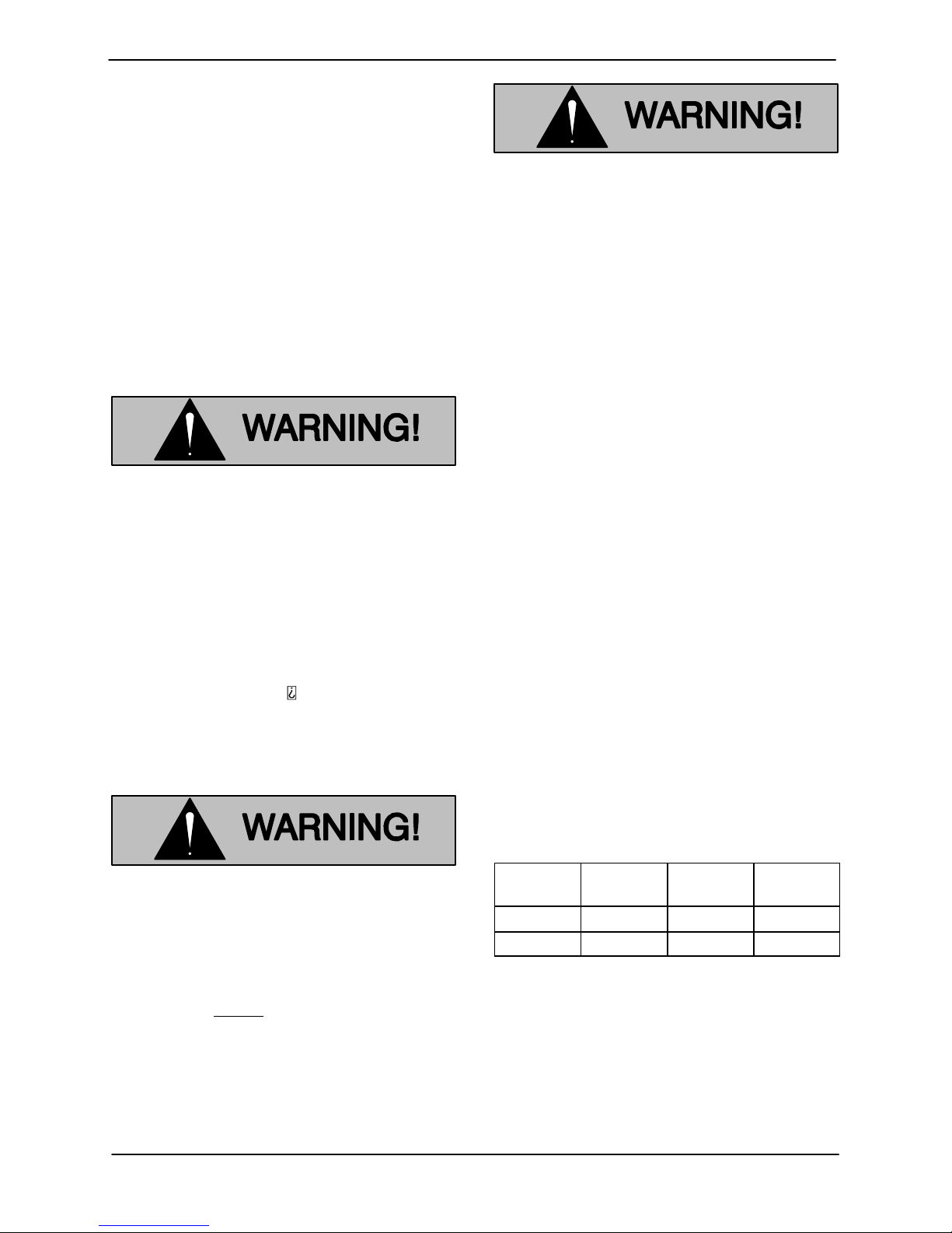
c. Buried electrode: If rock or stone prevents
embedding the full 8 foot (2,4 m) length of the
ground rod, bury it horizontally in a trench.
OM-06520SM SERIES
Space the ground rod or plates at least 6 feet
(1,8 m) from any other electrode or ground
rod, such as those used for signal circuits, ra
dio grounds, lightning rods, etc.
The earth surrounding the ground rod or plate
must contain enough moisture to make a
good electrical connection. In dry or sandy ar
eas, pour water around the rod, or consult
qualified personnel to devise a method of im
proving the connection.
The electrical power used to operate
this pump is high enough to cause inju
ry or death. Make certain that the control
box is properly grounded after installa
tion.
Field Wiring Connections (Incoming Power)
The trailing cable from the power source to the
control box must be furnished by the customer.
The cable must be flame resistant, protected by
an instantaneous circuit breaker, and meet the
specifications indicated in Table B-2 in this sec
tion.
Do not open the control box in an explo
sive atmosphere. When sealed, the con
trol box is explosion proof to prevent the
ignition of combustible gases. Opening
the box in an explosive atmosphere
could result in fire or explosion.
The pump control is designed to regulate a 460 or
575 volt, 3 phase, 60 hertz power supply (see Table
4 for control box specifications). The field wiring
must be properly sized to ensure an adequate volt
age supply. The voltage available at the motor
must be within the range indicated in Table B-5.
To calculate the voltage available at the motor, pro
ceed as follows:
a. Measure the incoming voltage across lines 1
& 2, 2 & 3, and 1 & 3 while the pump is oper
ating at full capacity. See the wiring dia
grams in this section for power supply con
nections.
b. Next, subtract the motor cable voltage drop
(see Table 6, Pump Power Cable Specifica
tions).
c. Do not continue to operate the pump if this
voltage is not within the recommended limits.
Obtain the services of a qualified electrician to
determine the correct field wiring size and
other details to insure an adequate voltage
supply to the pump.
The electrical power used to operate
this pump is high enough to cause inju
ry or death. Obtain the services of a qu
alified electrician to make all electrical
connections. Make certain that the
pump and enclosure are properly
grounded; never use gas pipe as an
electrical ground. Be sure that the in
coming power matches the voltage and
phase of the pump and control before
connecting the power source. Do not
run the pump if the voltage is not within
the limits.
Table B-5. Pump Motor Voltage Limits
Nominal
Voltage Phase
460 3 420 500
575 3 520 630
Use the packing gland nuts to secure and seal the
incoming field wiring to the control box. make cer
tain all connections are tight and that cable entry
points are rainproof. Support the cable weight, if
required, to prevent excessive strain on cable
clamps and cable.
Minimum
Voltage
Maximum
Voltage
NOTE
After the power cables have been connected to the
PAGE B - 11INSTALLATION
Page 19
OM-06520 SM SERIES
control box, the packing gland nuts must be wired
and sealed before operation. See Terminal Hous
ing And Power Cable Reassembly in Section E for
instructions.
Pump Power Cable Connections
The electrical power used to operate
this pump is high enough to cause inju
ry or death. Obtain the services of a qu
alified electrician to make all electrical
connections. Make certain that incom
ing power to the control box is in the off
position and locked out, or that the pow
er supply to the control box has been
otherwise cut off and locked out, before
connecting power or accessory cables.
The standard pump is provided with a 50 foot (15,2
meters) power cable (see table 6 for power cable
specifications). If a longer cable is required, an op
tional cable assembly must be ordered from the
factory. Splicing of the power cable is not recom
mended by the Gorman‐Rupp Company due to
safety and warranty considerations.
Never attempt to alter the length or re
pair any power cable with a splice. The
pump motor and cable must be com
pletely waterproof. Injury or death may
result from alterations.
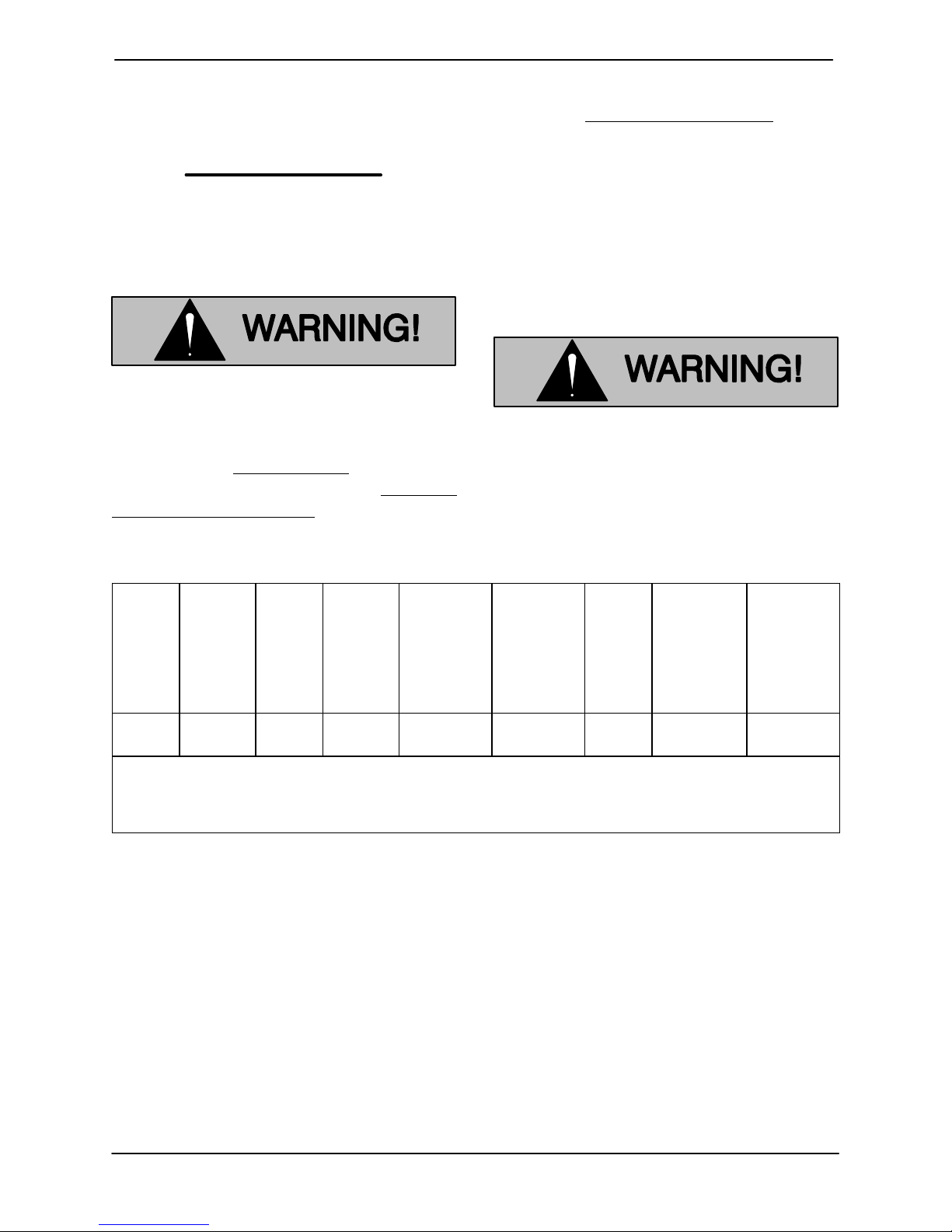
Table B-6. Pump Power Cable Specifications Model SM3C65
DC
Resistance
(ohms) at
Cable
AWG
Pump
Model
SM3C 460/3
NOTE: *Amp Rating at 30_C (86_F). Applies only to type SPC cable. Refer to manufacturer's
When necessary to change or connect the pump
power cable to the control box, make certain the in
coming power is OFF and LOCKED OUT. Make
certain the control box is PROPERLY GROUNDED
and that the electrical data on the control matches
the motor name plate data.
Voltage/
Phase
575/3
specifications for other cable.
**Amp Rating at 40_C (104_F). Applies only to type SPC cable. Refer to manufacturer's
specifications for other cable.
Cable
Size
12 0.89
O.D.
Inches
(mm)
(22,6)
Conductor
Dia.
Inches
(mm)
.10
(2,5)
Amp
Rating
(See Note
below)
30 SPC 1.72 3.72
Connect the pump power cable to the control box
as shown Figure B-6. Use conduit or cable
clamps to secure the power and accessory cables
to the control box. Make certain that all connec
tions are tight and that cable entry points are
rainproof.
Cable
Type
25_C
(77_F) per
1000 ft.
(305 m)
Voltage
Drop per
100 ft.
(30,5m) at
Max. Load
2.96
PAGE B - 12 INSTALLATION
Page 20
OM-06520SM SERIES
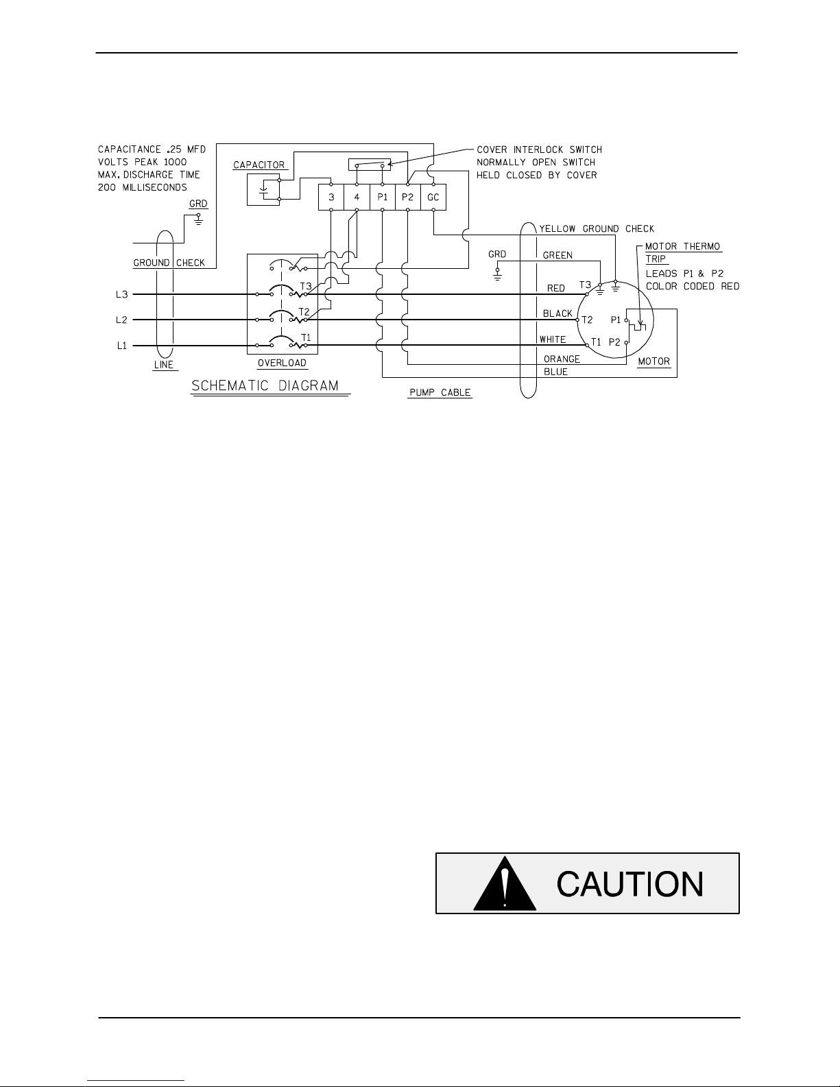
Figure B-6. Pump Power Cable Connection Diagram (All Models)
PUMP POWER CABLE CONNECTION INSTRUCTIONS
1. Run the pump cable through the packing
gland nuts and washers (the concave side of
the washer should toward the packing) at the
bottom of the control.
2. Connect the white, black, and red power
leads to terminals “T1”, “T2”, and “T3”, re
spectively.
3. Connect the green ground lead to terminal
“GRD”.
4. Connect the yellow ground check lead to ter
minal “GC”.
5. Connect the blue control lead to terminal
“P1”.
6. Connect the orange control lead to terminal
“P2”.
gland nut to the enclosure. Use the hole in the
hex nut and the hole at the top left of the enclo
sure to prevent loosening of the nut.
LIQUID LEVEL CONTROL
The standard pump is not furnished with a means
to automatically regulate liquid level. However, the
pump may be controlled to perform dewatering
functions by using an optional control box avail
able from the factory. The control utilizes a
bulb‐type sensing device, where a bulb raises or
lowers (floats) with the liquid level, thus activating
an enclosed miniature switch.
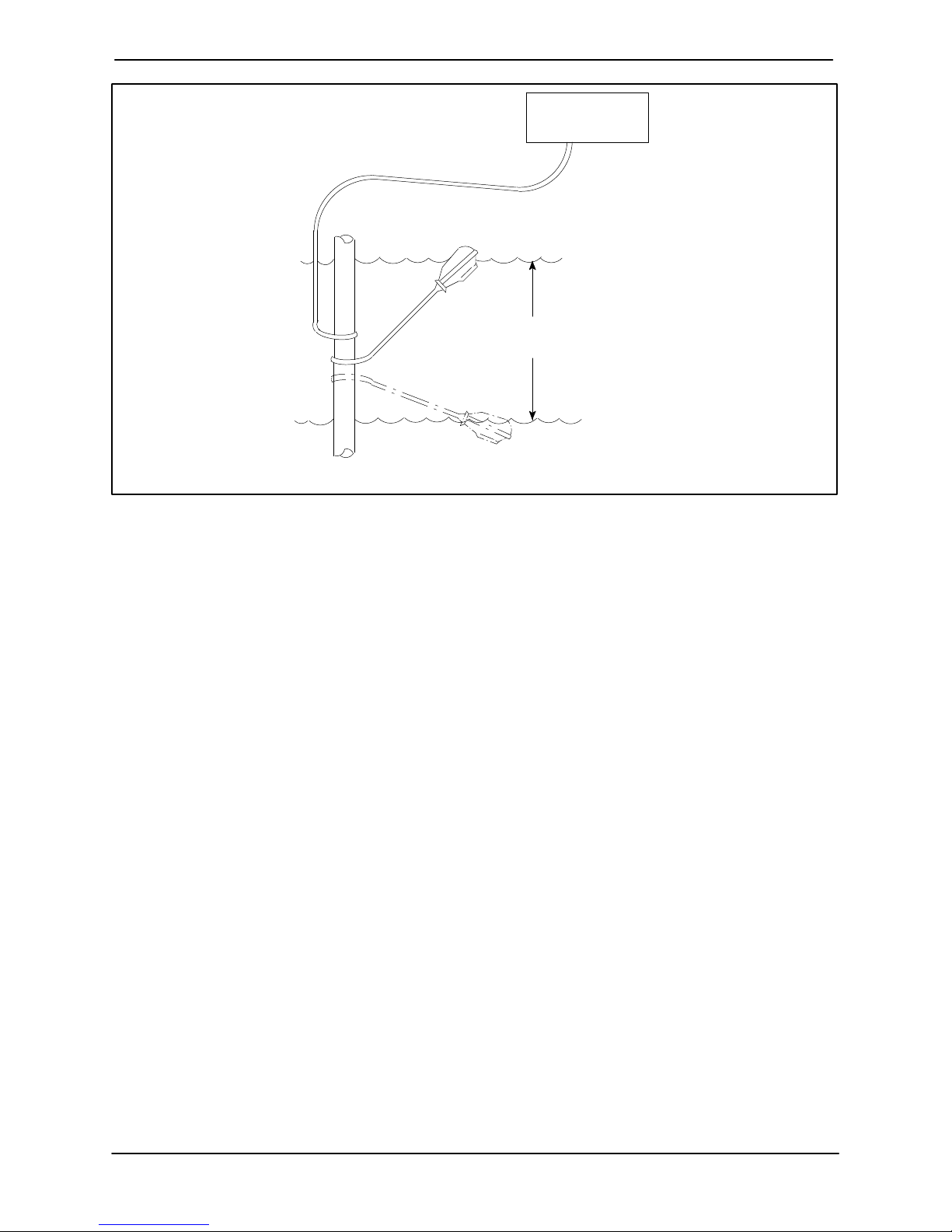
Refer to Figure B-7 for a typical bulb‐type float in
stallation.
7. Install the packing in the gland with the wash
ers on each side, and tighten the packing
gland nut. With the nuts tight and the packing
fully compressed, there must be a minimum
space of 1/8 inch between the bottom of the
nut and the enclosure.
8. Use the seal wire (P/N 31311-004) and lead
seal (P/N 21188-002) to secure the packing
The float must be positioned to allow 10
minutes between starts. If the pump motor
cycles more than 6 starts per hour, it will
over‐heat, resulting in damage to the mo
tor windings or control box components.
PAGE B - 13INSTALLATION
Page 21
OM-06520 SM SERIES
PUMP
CONTROL BOX
TO LEVEL CONTROL CIRCUIT
IN MAIN CONTROL BOX
LIQUID LEVEL
RANGE
OFF
DEWATERING
ON (FILLING)
BULB (FLOAT TYPE)
Figure B-7. Liquid Level Devices
PAGE B - 14 INSTALLATION
Page 22
SM SERIES
OM-06520
OPERATION - SECTION C
Review all SAFETY information in Section A.
Follow the instructions on all tags, labels and
decals attached to the pump and control box.
CONTROL BOX FUNCTION
A control box is provided to facilitate operation of
the pump. It contains controls for starting and stop
ping the pump, and provides overload protection
for the pump motor.
The pump is designed to be operated
through the control box furnished with
the pump. The control box provides
overload protection and power control.
Do not connect the pump motor directly
to the incoming power lines.
Since operation of the pump motor is de
pendent upon the quality and performance
of the electrical controls, the pump warran
ty is valid only when controls have been
specified or provided by the Gor
man‐Rupp Company.
permit pump operation. The circuit breakers
will open or “trip” automatically in the event
of a short circuit overload current, or thermal
excess within the pump motor or electrical
system. When tripped, move the control
handle to OFF and back to ON to reset the
circuit breakers.
D The control box contains an integral safety
switch which automatically “trips” the circuit
breakers when the cover is removed. Never
remove the cover in an explosive atmos
phere. Make certain incoming power is OFF
and LOCKED OUT.
D The motor is thermally protected by a ther
mostat within the stator. In the event of motor
overheating, the thermostat will open and
automatically “trip” the control box circuit
breakers. The motor will not restart until the
circuit breakers are reset.
NOTE
If the circuit breaker trips, do not reset it immedi
ately. Wait at least ten minutes before resetting the
control handle back to the ON position. If the over
load unit continues to trip, operational problems ex
ist. See TROUBLESHOOTING .
PUMP OPERATION
Component Function
The control box contains the following hand oper
ated switches and controls:
D The control handle operates the control
box circuit breakers. In the OFF position, the
control handle opens the circuit breakers to
interrupt incoming power through the con
trol box and prevent pump operation. In the
ON position, it closes the circuit breakers to
OPERATION PAGE C - 1
This pump is designed to handle most
non volatile, non flammable liquids
encountered in mine dewatering. Do not
attempt to pump volatile, explosive, or
flammable materials, or any liquids
which may damage the pump or endan
ger personnel as a result of pump fail
ure.
Page 23
OM-06520
SM SERIES
Liquid Temperature And Overheating
The maximum liquid temperature for this pump is
120_F (102.2_C). Do not apply the pump at higher
operating temperatures.
Approach the pump cautiously after it
has been running. Although the motor is
cooled by the liquid being pumped, nor
mal operating temperatures can be high
enough to cause burns. The tempera
ture will be especially high if operated
against a closed discharge valve. Never
operate against a closed discharge
valve for long periods of time.
If overheating does occur, stop the pump immedi
ately and allow it to cool before servicing it. Ap
proach any overheated pump cautiously.
Checking Pump Rotation
Do not open the control box in an explo
sive atmosphere. When sealed, the con
trol box is explosion proof to prevent the
ignition of combustible gases. Opening
the box in an explosive atmosphere
could result in fire or explosion.
Check the direction of pump rotation before opera
tion to ensure that the impeller is rotating in the cor
rect direction.
Suspend the pump from the lifting device fitted on
the pump. Turn the pump on momentarily and note
the direction of twist. For correct rotation and op
eration, the twist must be in a counterclockwise
direction when viewed from the top (see Figure
C-1).
Overheated pumps can cause severe
burns and injuries. If overheating of the
pump occurs:
1. Stop the pump immediately.
2. Ventilate the area.
3. Allow the pump to cool.
4. Check the temperature before
servicing.
5. Vent the pump slowly and cau
tiously.
6. Refer to instructions in this manual
before restarting the pump.
Secure the pump during rotation to pre
vent coiling of the power cable.
If the pump twists clockwise on start, interchange
any two motor leads at the control box.
The electrical power used to operate
this pump is high enough to cause inju
ry or death. Make certain that incoming
power is off and locked out before inter
changing motor leads.
OPERATIONPAGE C - 2
Page 24
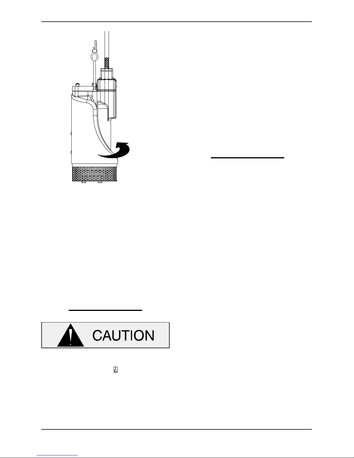
SM SERIES
DIRECTION OF
KICKBACK
AT STARTUP
OM-06520
STOPPING
To stop the pump, turn the control handle OFF,
thereby opening the circuit breaker.
This does not terminate incoming power through
the field wiring connected to the control box.
After stopping the pump, be sure to perform all re
quired maintenance and preservation procedures.
NOTE
It is recommended that a check valve or throttling
valve be installed in the discharge line if there is any
possibility of siphoning or back flow when the
pump is shut off.
OPERATIONAL CHECKS
Figure C-1. Checking Pump Rotation
STARTING
After the pump and control box have been in
stalled, start the pump as follows.
NOTE
Before actual operation, check the direction of im
peller rotation to ensure that the pump is properly
wired. See Checking Pump Rotation in this sec
tion.
Never start the pump more than 6 times per
hour. If the pump motor does not cool be
tween starts, it will over heat, resulting in
damage to the motor windings or control
box components.
Move the control handle to the ON position. The
pump motor will start running, and pumping
should begin. Since the pump is submerged, prim
ing is not required.
Check the pump for proper operation when it is first
started and periodically thereafter to identify minor
problems.
Check the pump for unusual noises or excessive
vibration while it is operating. If noise or vibration is
excessive, stop the pump and refer to the
troubleshooting chart for possible causes.
Check the pump strainer screen for clogging
caused by stones, sticks, or other debris. Clean
the strainer screen when required. In some cases,
stopping the pump momentarily may back flush
the strainer screen, purging most of the debris
from it. If this fails to clean the screen, remove the
pump from the sump and remove the debris manu
ally (see PUMP END DISASSEMBLY in Section
E).
Never introduce air or steam pressure into the
pump casing or piping to remove a blockage. This
could result in personal injury or damage to the
equipment. If backflushing is absolutely neces
sary, liquid pressure must be limited to 50% of the
maximum permissible operating pressure shown
on the pump performance curve (see MAINTE
NANCE AND REPAIR, Section E).
Check the pump for overheating. The pump could
overheat if operated against a closed discharge
valve, or if subjected to repeated start cycles.
OPERATION PAGE C - 3
Page 25
OM-06520
SM SERIES
COLD WEATHER PRESERVATION
In freezing temperatures, the pump will not freeze
as long as it is submerged in liquid. If the pump
casing is not submerged, or if the liquid begins to
freeze, remove the pump from the sump or wet well
and allow it to dry thoroughly. Run the pump for two
or three minutes to dry the inner walls.
If the pump freezes, move it into a warm area until
completely thawed, or submerge it into the liquid. If
the liquid is near freezing, the pump must be sub
merged for an extended period of time. Start the
pump and check for shaft rotation. if still frozen, al
low additional thawing time before attempting to
restart.
Do not attempt to thaw the pump by us
ing a torch or other source of flame. This
could damage gaskets or heat the oil
within the pump above the critical point
and cause the pump to rupture or ex
plode.
LUBRICATION
Do not remove plates, covers, gauges,
pipe plugs or fittings from an over
heated pump. Vapor pressure within the
pump can cause parts being disen
gaged to be ejected with great force. Al
low the pump to completely cool before
servicing.
On a new pump, check the oil level in the seal cav
ity before initial startup, after the first two weeks of
operation, and every month thereafter.
Before installing or removing the lubrication
plug(s), always clean the area around the plug(s)
to prevent contamination.
Draining Oil
Refer to the parts list in MAINTENANCE AND RE
PAIR, Section E for drain plug location.
Remove the drain plug slowly to release any pres
sure. Install a short pipe nipple in the hole. Place
a clean container under the plug and using a hoist,
tilt the pump at an angle of approximately 60_.
Condition of Oil
Check the condition of the oil drained from the
pump. Clear oil indicates that the pump seal(s) are
functioning properly. If the oil is milky or contains
a small amount of water, it must be changed.
If the oil contains a large amount of water, it must
be changed, and the seal(s) must be checked be
fore the pump is put back in operation (refer to
MAINTENANCE AND REPAIR, Section E).
Adding Oil
Refer to Table B-2 in INSTALLATION for the oil ca
pacity and position for filling the seal cavity in the
pump.
The grade of lubricant used is critical to the opera
tion of this pump. Use premium quality submers
ible pump oil as specified in the following table. Oil
must be stored in a clean, tightly closed container
in a reasonably dry environment.
When lubricating the seal cavity, remove the lubri
cation plug as indicated in Draining Oil, and posi
tion the pump as indicated in Table B-2 in
INSTALLATION. Add premium quality submers
ible pump oil (See Table C-1) through this plug
hole. If the pump is to be positioned vertically or at
an angle, fill the cavity to the bottom of the plug
hole. If the pump is to be positioned horizontally,
completely fill the cavity.
Install and tighten the lubrication plug.
OPERATIONPAGE C - 4
Page 26

SM SERIES
Table C-1. Pump Oil Specifications
Specifications:
Type Premium high viscosity index, anti‐wear hydraulic oil..............................
Viscosity (SSU @ 104_F [40_C]) 110 to 155.........................................
Viscosity (SSU @ 210
_
F [100_C]) 40 to 50...........................................
Dielectric 26,000 (volts‐min)........................................................
Recommended supplier:
Gulf Oil Company Gulf Harmony AW Hydraulic Fluid MG 32............................
Acceptable alternate suppliers:
Gulf Oil Company Gulf Harmony 32 AW..............................................
Texas Oil Company Rando HD 32 or HD AZ 32........................................
Sun Oil Company Sunvis 816 or 916.................................................
BP (Also Boron) Energol‐HLP 32.....................................................
Shell Oil Company Tellus 32, Tellus T‐23 or T32.......................................
ARCO Duro 32...................................................................
Exxon (Also Esso) Nuto H 32........................................................
Petro‐Canada Harmony HVI 22......................................................
OM-06520
OPERATION PAGE C - 5
Page 27
TROUBLESHOOTING - SECTION D
Review all SAFETY information in Section A.
The following precautions should be
taken before attempting to service the
pump; otherwise, injury or death could
result.
1. Familiarize yourself with this man
ual and with all other literature
shipped with the pump.
2. Lock out incoming power to the
pump or control box to ensure that
the pump will remain inoperative.
3. Allow the pump to completely cool
if overheated.
4. Check the temperature before
opening any covers, plates or
plugs.
5. Close the discharge valve (if
used).
OM-06520SM SERIES
The electrical power used to operate
this pump is high enough to cause inju
ry or death. Obtain the services of a qu
alified electrician to troubleshoot, test
and/or service the electrical compo
nents of this pump.
NOTE
Many of the probable remedies listed below re
quire use of electrical test instruments; for specific
procedures, see ELECTRICAL TESTING following
the chart.
Table B‐1 Troubleshooting Chart
TROUBLE CAUSE REMEDY
PUMP FAILS TO
START, CIRCUIT
BREAKER NOT
TRIPPED
CIRCUIT BREAKER
TRIPS
Power source incompatible
with control box.
No voltage at line side of cir
cuit breaker.
Open circuit in motor wind
ings or power cable.
Defective motor power cable.
Low or high voltage, or exces
sive voltage drop between
pump and control box.
Defective insulation in motor
windings.
Impeller jammed due to de
bris or insufficient clearance.
Bearing(s) frozen.
Correct power source.
Check power source for blown fuse, open
overload unit, broken lead, or loose connec
tion.
Check continuity.
Check for and replace defective unit.
Measure voltage at control box. Check that
wiring is correct type, size, and length. (See
Field Wiring Connections, Operations And
Maintenance Manual.
Check insulation resistance; check continuity.
Disassemble pump and check impeller.
Disassemble pump and check bearing(s).
TROUBLESHOOTING PAGE D - 1
Page 28
Table B‐1 Troubleshooting Chart (continued)
TROUBLE CAUSE REMEDY
SM SERIESOM-06520
MOTOR RUNS, BUT
PUMP FAILS TO DE
LIVER RATED DIS
CHARGE
Discharge head too high.
Low or incorrect voltage.
Discharge throttling valve par
tially closed; check that valve
is installed improperly.
Discharge line clogged or re
stricted; hose kinked.
Liquid being pumped too
thick.
Strainer screen or impeller
clogged.
Insufficient liquid in sump or
tank.
Worn impeller vanes; exces
sive impeller clearance.
Pump running backwards.
Reduce discharge head, or install staging
adaptor and additional pump.
Measure control box voltage, both when
pump is running and when shut off.
Open discharge valve fully; check piping in
stallation.
Check discharge lines; straighten hose.
Dilute liquid if possible.
Clear clog(s). Stop pump; back flow may
flush away debris.
Stop pump until liquid level rises.
Check impeller and clearance. See PUMP
END REASSEMBLY.
Check direction of rotation and correct by in
terchanging any two motor leads at control
box. (See Pump Rotation, Section C).
PUMP RUNS WITH
EXCESSIVE NOISE
OR VIBRATION
Pumping entrained air.
Damaged or unbalanced im
peller.
Discharge piping not properly
supported.
Impeller jammed or loose.
Pump cavitation.
Motor shaft or bearings defec
tive.
ELECTRICAL TESTING
If you suspect that pump malfunctions are caused
by defects in the motor, power cable or control box,
perform the following checks to help isolate the de
fective part.
Check liquid level in sump; check position of
pump and liquid level sensing device(s).
Replace impeller.
Check piping installation.
Check impeller.
Reduce discharge head, or restrict flow on
low head applications.
Disassemble pump and check motor and
bearings.
Obtain the services of a qualified elec
trician to troubleshoot, test and/or ser
vice the electrical components of this
pump.
TROUBLESHOOTINGPAGE D - 2
Page 29
Be certain to refer to the wiring diagram(s)
before reconnecting any electrical compo
nents which have been disconnected.
Test Equipment
A volt/amp/ohmmeter and megohmeter of ade
quate range and quality will be required to conduct
the following electrical tests. The suggested equip
ment indicated below is commercially available, or
an equivalent substitute may be used.
Equipment Use
Ammeter/
Voltmeter
Ohmmeter To measure resistance
To check AC Voltage
and current (amperage)
(ohms) to ground
OM-06520SM SERIES
be the same at each condition, as accurate
ly as the meter will read. Nominal amperage
values are listed in Table 1, but these apply
only when the actual voltage at the site is the
nominal voltage listed.
c. If the voltages are balanced with the pump
off, but are unbalanced when the pump is
running, a thorough check of the power
source, all interconnecting cables, and the
pump motor is required to isolate the defect.
Motor And Motor Power Cable Continuity
To check continuity, zero‐balance the ohmmeter
set at the RX1 scale, and test as follows:
a Disconnect the motor power cable leads
from the control box and connect the test
leads to any two of the three power cable
leads (not to the green ground lead or yellow
ground check lead). If there is a high resis
tance reading on the ohmmeter, there is an
open or broken circuit cause a break in the
power cable or motor windings, or by a bad
connection between the motor and the pow
er cable. Switch one test lead to the third
power lead, and test again.
Voltage Imbalance
Each phase of the incoming three‐phase power
must be balanced with the other two as accurately
as a commercial voltmeter will read. If the phases
are balanced, check out the motor as described
below. If the phases are out of balance, contact
your power company and request that they correct
the condition.
a. Use a voltmeter, amprobe, or equivalent me
ter to read the voltage across terminals 1 &
2, 2 & 3, and 1 & 3 in the control box. All three
measured voltages must be the same, as
accurately as the meter will read. If possible,
measure the voltage with the pump off, with
the pump running but out of the water, and
with the pump running in the water at full
load. All the measured voltages at each con
dition must be the same.
b. Use an amprobe or equivalent meter to
measure the current draw of each phase
while the pump is running at full load and at
no load. All three amperage readings must
b. If an open or broken circuit is indicated,
check the power cable for obvious damage,
and replace as necessary (see MAINTE
NANCE AND REPAIR). If there is no appar
ent damage to the motor cable, remove the
terminal housing (see MAINTENANCE
AND REPAIR) and check the continuity of
each power cable lead at the terminal posts.
c. If an open circuit still exists after each lead
(terminal) has been tested and tightened,
then the entire motor power cable must be
replaced. Splicing or other means of repair
are not recommended.
d. If no break is found in the power cable,
check the motor leads for continuity. If the
test reading indicates an open or broken cir
cuit, there is an open circuit in the motor.
NOTE
It is recommended that a pump with a defective mo
tor be returned to Gorman‐Rupp, or to one of the
Gorman‐Rupp authorized Submersible Repair en
ters.
TROUBLESHOOTING PAGE D - 3
Page 30

Insulation Resistance
To check insulation, zero‐balance the ohmmeter
set at the RX100K scale, and test as follows:
a. Disconnect the motor power cable leads
from the control box. Connect one test lead
to the power cable green ground lead, and
touch the other test lead to each of the three
power leads in turn.
b. The reading obtained will indicate resis
tance values in both the power cable and the
motor windings. If the resistance reading is
infinity (1), the insulation is in good condi
SM SERIESOM-06520
tion. If the reading is between infinity (1)
and 1 megohm, the insulation is acceptable
but should be rechecked periodically. If the
reading is less than 1 megohm, the insula
tion should be checked more closely; a
reading of zero indicates that the power
cable or the motor is grounded.
c. To determine whether the power cable or
the motor is grounded, remove the terminal
housing (see MAINTENANCE AND RE
PAIR), disconnect the motor leads from the
motor terminals, and test the power cable
leads and motor leads separately.
TROUBLESHOOTINGPAGE D - 4
Page 31
SM SERIES OM-06520
PUMP MAINTENANCE AND REPAIR - SECTION E
MAINTENANCE AND REPAIR OF THE WEARING PARTS OF THE PUMP WILL MAINTAIN PEAK
OPERATING PERFORMANCE.
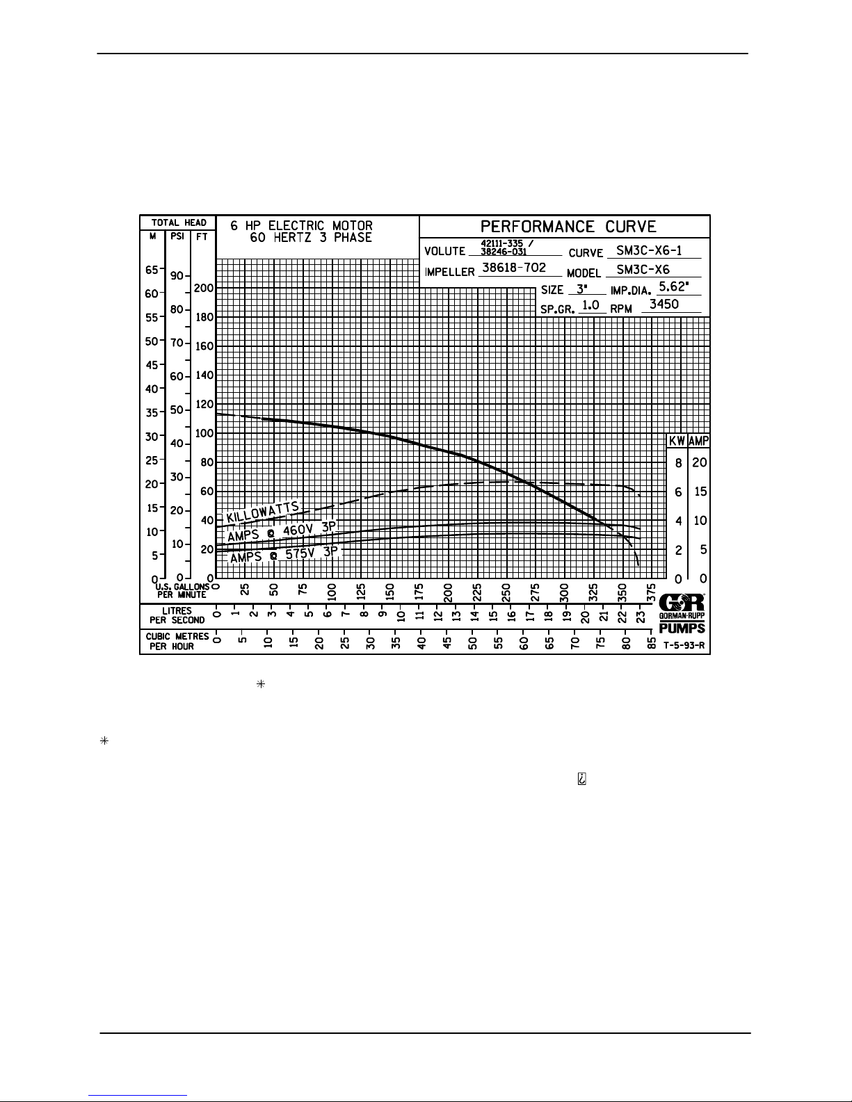
STANDARD PERFORMANCE FOR PUMP MODEL
SM3C65-X6 (All Voltages)
Based on 70_F (21_C) clear water at sea level.
Since pump installations are seldom identical, your
performance may be different due to such factors
as viscosity, specific gravity, elevation, tempera
ture, and impeller trim.
MAINTENANCE & REPAIR PAGE E - 1
If your pump serial number is followed by an “N”,
your pump is NOT a standard production model.
Contact the Gorman Rupp Company to verify
performance or part numbers.
Page 32
OM-06518 S SERIES
ILLUSTRATION
PARTS PAGE
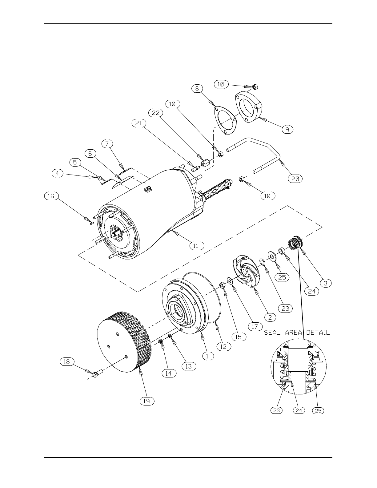
Figure E-1. Pump Model SM3C65-X6 (All Voltages)
MAINTENANCE & REPAIRPAGE E - 2
Page 33
SM SERIES OM-06520
PARTS LIST
Pump Model SM3C65-X6 (All Voltages)
(From S/N 1546391 Up)
ITEM
NO.
1 SUCTION HEAD 38246-031 1718H 1
2 IMPELLER 38618-702 1718H 1
3 SEAL ASSEMBLY 46512-071 --- 1
4 DRIVE SCREW BM#04-03 17090 16
5 CW OF PA APPROVAL PLATE 2613FL 17040 1
6 MSHA APPROVAL PLATE 2613ES 17040 2
7 NAMEPLATE 2613DD 17040 1
8 FLANGE GASKET 38687-045 19370 1
9 DISCHARGE FLANGE 38641-006 17070 1
10 HEX NUT D08 17090 5
11 SUBMERSIBLE MOTOR ASSEMBLY:
12 O‐RING 25154-270 --- 1
13 LOCK WASHER J06 17090 6
14 HEX NUT D06 17090 6
15 HEX NUT 22561-165 --- 1
16 KEY N0302-1/2 17090 1
17 FLAT WASHER KB08 17090 1
18 NYLOCK CAP SCREW BT0806 17090 3
19 STRAINER SCREEN ASSEMBLY 46611-010 24170 1
20 HOISTING BAIL 31926-009 17130 1
21 STUD C0806 17090 1
22 COUPLING NUT 31811-019 17130 1
23 IMP ADJ SHIM SET 2Y 17090 REF
24 SHAFT SLEEVE 13878 17090 1
25 SPRING RETAINER 8793 17090 1
NOT SHOWN:
OPTIONAL:
PART NAME
460V 47111-096 --- 1
575V 47111-097 --- 1
460V CONTROL BOX 47631-148 --- 1
575V CONTROL BOX 47631-149 --- 1
STAGING ADAPTOR KIT 48272-015 --- 1
460V FLOAT CONTROL BOX 47631-171 --- 1
575V FLOAT CONTROL BOX 47631-172 --- 1
PART
NUMBER
MAT'L
CODE
QTY
INDICATES PARTS RECOMMENDED FOR STOCK
MAINTENANCE & REPAIR PAGE E - 3
Page 34
OM-06518 S SERIES
ILLUSTRATION
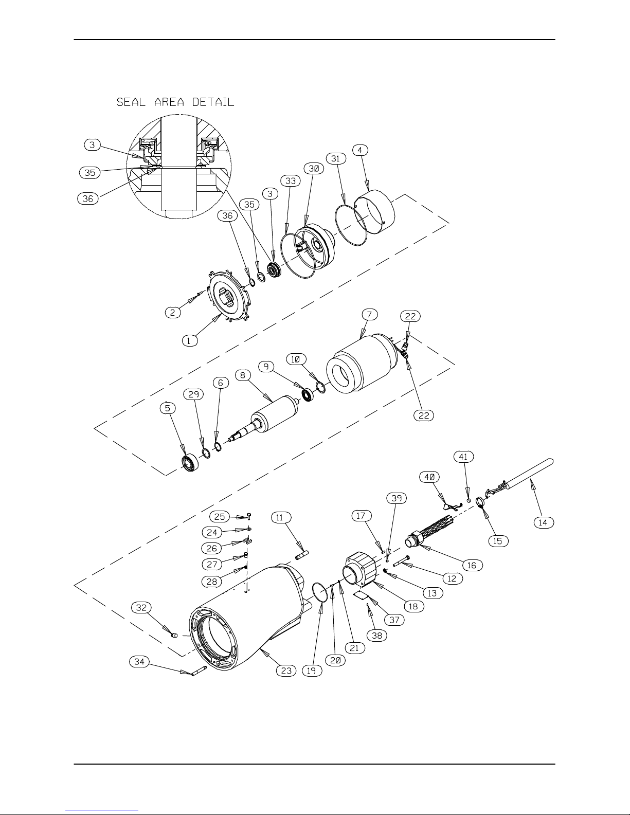
Figure E-2. Submersible Motor Assemblies
MAINTENANCE & REPAIRPAGE E - 4
Page 35
SM SERIES OM-06520
PARTS LIST
Submersible Motor Assemblies
ITEM
PART NAME PART
NO.
1 SEAL PLATE: 38272-350 1718H 1
2 FH MACH SCREW Y#10-03 17090 2
3 MECH SEAL 25276-031 --- 1
4 MOTOR BUSHING 31173-017 23010 1
5 BALL BEARING 23425-007 --- 1
6 SNAP RING S1831 --- 1
7 STATOR:
460V 47113-817 --- 1
575V 47113-818 --- 1
8 ROTOR & SHAFT ASSY 47112-811 --- 1
9 BALL BEARING 23257-009 --- 1
10 SPRING WASHER S1554 --- 1
11 STUD C0809 17090 3
12 HEX HEAD CAP SCREW B0511 17090 4
13 LOCK WASHER J05 17090 4
14 SUB PUMP CABLE 47351-011 --- 1
15 HOSE CLAMP 26518-766 --- 1
16 CABLE GRIP ASSY 27111-816 --- 1
17 SET SCREW GA0402 17090 1
18 TERMINAL HOUSING 38381-225 17040 1
19 O‐RING 25154-149 --- 1
20 MACHINE SCREW X#10-01-1/2 14990 2
21 LOCK WASHER AK#10 15991 2
NUMBER
INDICATES PARTS RECOMMENDED FOR STOCK
MAT'L
CODE
QTY ITEM
NO.
22 WIRE CONNECTOR S1718 --- 5
23 MOTOR HOUSING 38311-069 17040 1
24 FLAT WASHER KB04 17040 1
25 NYLOCK CAP SCREW BT0403 17040 1
26 LOCK CLIP 33645-008 17040 1
27 PIPE PLUG 38649-022 17090 1
28 ALLEN HD SET SCREW GA0501-1/4 15990 1
29 BEARING SPACER 21161-401 --- 1
30 INTERMEDIATE 38261-024 13040 1
31 O‐RING 25152-258 --- 1
32 PIPE PLUG P04 17090 1
33 O‐RING S2194 --- 1
34 STUD C0611 17090 6
35 ADJUSTING SHIM SET 2X 17090 1
36 RETAINING RING 24124-332 --- 1
37 CERTIFICATION PLATE 2613GX 17040 1
38 DRIVE SCREW BM#04-03 17090 4
39 SET SCREW GA0401 17090 1
40 14” LG SST WIRE 14964-103 --- 1
41 LEAD SEAL 21188-002 --- 1
NOT SHOWN:
PART NAME PART
NUMBER
DOW CORING SILICONE ADHESIVE (10.1 OZ.)
18771-106 --- 1
MAT'L
CODE
QTY
MAINTENANCE & REPAIR PAGE E - 5
Page 36
OM-06520SM SERIES
PUMP END DISASSEMBLY
Review all SAFETY information in Section A.
Follow the instructions on all tags, label and decals
attached to the pump.
All functions performed by the customer on the
pump or control must be done in accordance with
MSHA, schedule 2G regulations to ensure the ex
plosion‐proof integrity. No alterations of original
design may be made without the consent of the
Gorman‐Rupp Company and MSHA.
The electrical power used to operate
this pump is high enough to cause inju
ry or death. Make certain that the control
handle on the control box is in the off po
sition and locked out, or that the power
supply to the control box has been
otherwise cut off and locked out, before
attempting to open or service the pump
assembly. Tag electrical circuits to pre
vent accidental start‐up.
Do not open the control box in an explo
sive atmosphere. When sealed, the con
trol box is explosion proof to prevent the
ignition of combustible gases. Opening
the box in an explosive atmosphere
could result in fire or explosion.
Before attempting to service the pump or control,
terminate the power supply to the control box.
Close the discharge throttling valve, if so
equipped.
hoists, chains, slings or cables are in
good working condition and of suffi
cient capacity and that they are posi
tioned so that loads will be balanced
and the pump or components will not be
damaged when lifting. Do not attempt to
lift this pump by the motor or control
cables, or the piping. Attach proper lift
ing equipment to the lifting bail fitted on
the pump. Lift the pump or component
only as high as necessary and keep per
sonnel away from suspended objects.
Use the hoisting bail to remove the pump from the
wet well or sump, and move it to a location where
the discharge line can be removed. It is not neces
sary to disconnect a flexible discharge hose before
removing the pump. If rigid discharge piping is
used, disconnect the piping before attempting to
move the pump.
Select a suitable location, preferably indoors, to
perform the degree of maintenance required. If the
motor housing is to be opened, the work must be
done in a clean, well‐equipped shop. All mainte
nance functions must be done by qualified person
nel.
Check the chart in TROUBLESHOOTING, Section
D of this manual, to determine the nature of the
pump problem. If the problem is mechanical in na
ture, such as worn pump parts, seal replacement,
lubrication, etc., refer to PUMP END DISASSEM
BLY for instructions.
If the problem is electrical, complete disassembly
may not be required. Refer to Electrical Testing in
TROUBLESHOOTING, Section D, and have a
qualified electrician check the control box, cable
and terminal housing. If the problem is determined
to be in the motor, proceed with PUMP END DIS
ASSEMBLY, followed by MOTOR DISASSEMBLY.
Otherwise, see Terminal Housing And Power Ca
ble Disassembly.
Death or serious personal injury and
damage to the pump or components
can occur if proper lifting procedures
are not observed. Make certain that
PAGE E - 6 MAINTENANCE AND REPAIR
Carefully inspect any O‐rings or gaskets before re
moval and cleaning to determine if a proper seal
and compression existed prior to disassembly. If
sealing was faulty or questionable, the cause must
be determined and corrected before reassembly.
All gaskets and most O‐rings must be replaced if
disturbed. Repair gaskets and O‐rings are listed in
the Parts List manual.
Page 37
SM SERIESOM-06520
Strainer and Suction Head Removal
(Figure E-1)
To remove the strainer (19), raise the pump slightly,
or lay it on its side and disengage the hardware
(18).
With the strainer removed, disengage the hard
ware (13 and 14). Pry the suction head (1) out of
the motor assembly (11). Remove the suction
head O‐ring (12).
If the impeller (2) is clogged, the debris can usually
be removed without further disassembly.
Draining Oil From Seal Cavity
(Figure E-1)
If any further disassembly is to be performed on the
pump, the seal oil cavity must be drained.
and personnel to safely handle the pump until it is
secured. If inverting the pump is not practical, lay
the pump on its side and secure it to prevent roll
ing.
Impeller Removal
(Figure E-1)
Wedge a soft metal rod between the vanes of the
impeller (2) and the studs (34, Figure E-2) to pre
vent shaft rotation. Remove the impeller nut (15)
and washer (17). Remove the metal rod used to
prevent shaft rotation.
Install three 10-32 UNC-2B by 2‐inch long cap
screws (not supplied) in the holes in the impeller.
Use the capscrews and a suitable puller to pull the
impeller from the shaft. Use caution when remov
ing the impeller; tension on the seal spring will be
released. Retain the impeller key (16).
Remove the impeller adjusting shim set (23). For
ease of reassembly, tie and tag the shims or mea
sure and record their thickness.
Let the pump cool before removing the
seal cavity drain plug. Pressure built up
within a hot pump could cause the oil to
spray out when the plug is removed. Re
move the plug slowly and permit pressure
to vent to atmosphere.
With the pump in a vertical position, clean any dirt
from around the pipe plug (32, Figure E-2) and re
move the plug. Install a short 3/8 inch NPT nipple in
the hole. Tip the pump and drain the seal oil into a
clean container. Inspect the oil for water, dirt, or
cloudy condition which could indicate lower seal
failure or poor gasket seal.
Positioning Pump For Disassembly
(Figure E-1)
It is recommended that the pump be positioned
upside‐down during disassembly. To hold the
pump in the inverted position, screw a pipe into the
discharge flange (9) and clamp it in a large vise, or
remove the discharge flange and secure the flange
studs to a bench or work stand. Be careful not to
damage the terminal housing (18, Figure E-2)
while in this position. Use adequate equipment
Lower Seal Removal
(Figures E-1 and E-3)
Remove the spring retainer (25) and seal spring.
Carefully pull the sleeve (25) and rotating portion of
the lower seal assembly off the shaft as a unit.
Remove the spring retainer (26), and seal spring.
Carefully pull the sleeve (25) and rotating portion of
the lower seal assembly off the shaft as a unit.
Lubricate the sleeve adjacent to the seal, and work
oil up under the rubber bellows. Slide the rotating
portion of the seal off the sleeve.
See Figure 2 and remove the flat head machine
screws (2). Slide the seal plate (1) and the station
ary portion of the lower seal assembly off the shaft
as a unit. Remove the seal plate O‐ring (33).
Position the seal plate on a flat surface with the im
peller side down. Carefully press the stationary
portion of the seal out of the seal plate from the
back side.
The rotating and stationary seal elements are pre
cision finished and subject to wear. The complete
seal should be replaced with each overhaul to en
MAINTENANCE AND REPAIR PAGE E - 7
Page 38

OM-06520SM SERIES
sure trouble‐free operation. However, if the old seal
must be reused, wrap the seal faces individually in
clean tissue paper to prevent damage to the seal
ing surfaces.
If no further disassembly is required, proceed to
the appropriate areas in PUMP END REASSEMB
LY.
Upper Seal Removal
(Figures E-2 and E-3)
The intermediate (30) and upper seal assembly (3)
must be removed as a unit to determine if the upper
seal assembly is leaking, and to replace the seal if it
is leaking.
Carefully pull straight up on the impeller end of the
rotor shaft until the assembled intermediate, seal,
bearings (5 and 9), and shaft and rotor assembly
(8) are free from the motor housing (23).
Inspect the rotor, stator, and inside of the motor
housing for evidence of upper seal leakage. If no
leakage is observed, the seal can be reused. How
ever, if leakage is apparent, the intermediate and
seal assembly must be separated from the rotor
and shaft assembly. Cover the motor housing with
a clean cloth after inspection to prevent contami
nation.
during removal.
Remove the intermediate O‐ring (31).
If no further disassembly is required, proceed to
PUMP END REASSEMBLY.
NOTE
If the motor housing components are to be serv
iced, see MOTOR DISASSEMBLY in this section.
Do not reassemble the pump end components at
this time.
If no further disassembly is required, proceed to
PUMP END REASSEMBLY.
PUMP END REASSEMBLY
NOTE
Reuse of old O‐rings, gaskets, or shaft seal parts
will result in premature leakage or reduced pump
performance. It is strongly recommended that new
gaskets and shaft seal assemblies be used during
reassembly (see the parts lists for numbers).
Cleaning and Inspection of Pump Parts
If the seal assembly does not require replacement,
proceed to Cleaning And Inspection Of Pump
Parts, followed by Upper Seal Installation.
If seal replacement is required, place the interme
diate, seal, bearings, and shaft and rotor assembly
on a clean, dry work surface, and remove the re
taining ring (36) using snap ring pliers. Use caution
when removing the retaining ring; tension of the
seal spring will be released. Remove the adjusting
shims (35). Tie and tag the shims, or measure and
record their thickness for ease of reassembly.
Carefully slide the intermediate and seal assembly
off the shaft as a unit. Use a hammer and punch (or
other suitable tool) to tap the seal assembly out of
the intermediate from the back side.
NOTE
The seal assembly will be damaged or destroyed
PAGE E - 8 MAINTENANCE AND REPAIR
Carefully inspect any O‐rings or gaskets before re
moval and cleaning to determine if a proper seal
and compression existed prior to disassembly. If
sealing was faulty or questionable, the cause must
be determined and corrected before reassembly.
Replace any parts as required.
NOTE
The upper seal assembly will be damaged or de
stroyed if removed from the intermediate. If the seal
was not removed from the intermediate, clean and
inspect all pump end parts as follows, then reinstall
the seal assembly and intermediate as a unit.
Thoroughly clean all reusable parts with a soft cloth
soaked in cleaning solvent. Use a clean cloth
lightly dampened with solvent to clean the lower
end of the motor housing, intermediate, and seal
plate. Do not allow the solvent to enter the motor.
Page 39
Most cleaning solvents are toxic and
flammable. Use them only in a well ven
tilated area free from excessive heat,
sparks, and flame. Read and follow all
precautions printed on solvent contain
ers.
SM SERIESOM-06520
mediate O‐ring (31) and lightly lubricate it with oil.
Check to insure that the wavy washer (10) and mo
tor bushing (4) are properly positioned, and slide
the rotor and shaft assembly, bearings, intermedi
ate and seal assembly into the motor housing until
fully seated.
If a new seal is to be installed, do not unwrap it until
time of installation. Cleanliness of seal compo
nents is critical, especially the seal faces.
Remove all O‐rings and gaskets, and clean the
sealing surfaces of dirt or gasket material. Be care
ful not to scratch the surfaces.
Inspect the rotor shaft for damaged threads, scor
ing, or nicks. Remove nicks and burrs with a fine
file or emery cloth to restore original contours. If the
shaft is bent or severely damaged, the rotor and
shaft must be replaced as an assembly (see MO
TOR DISASSEMBLY).
Upper Seal Installation
(Figures E-2 and E-3)
If the upper seal assembly was not removed from
the intermediate at disassembly, replace the inter
Clean the rotor shaft and seal cavity area of the in
termediate (30). Be sure the area is dry and free of
lint and dirt. Do not permit cleaning solvent or de
bris to fall into the motor cavity.
Install a new O‐ring (31) in the groove in the inter
mediate and lightly lubricate it with oil. Carefully
slide the intermediate over the shaft until it is fully
seated over the lower bearing (5).
Check to insure that the wavy washer (10) and mo
tor bushing (4) are properly positioned, and care
fully lower the intermediate, bearings, and shaft
and rotor assembly into the motor housing. Press
the intermediate into the motor housing until fully
seated against the motor bushing.
Install the shaft seals as illustrated in Figure E-3.
MAINTENANCE AND REPAIR PAGE E - 9
Page 40
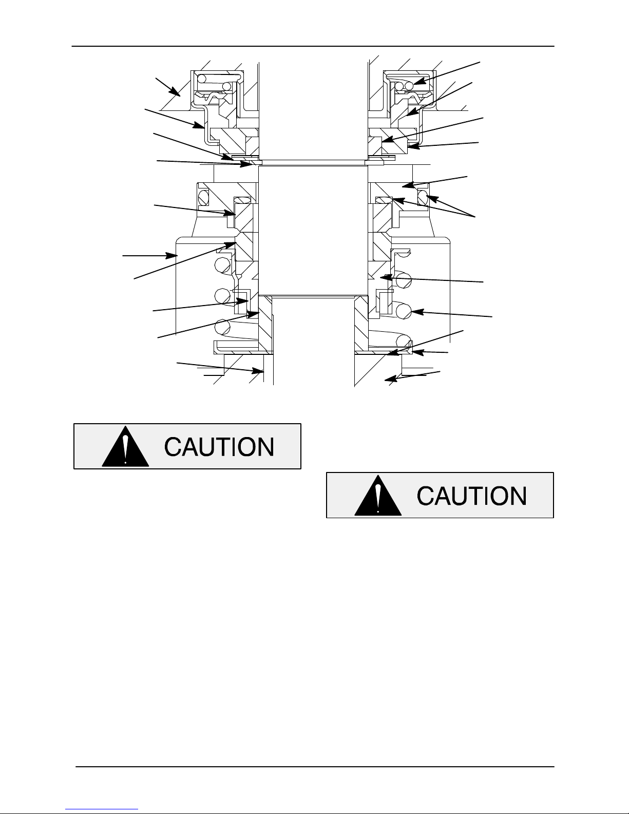
INTERMEDIATE
BELLOWS
RETAINER
ADJUSTING
SHIMS
RETAINING
RING
STATIONARY
ELEMENT
SEAL
PLATE
ROTATING
ELEMENT
ROTOR
AND
SHAFT
ASSY
OM-06520SM SERIES
SPRING
STATIONARY
ELEMENT
BELLOWS
ROTATING
ELEMENT
STATIONARY
SEAT
STATIONARY
SEAT O‐RINGS
BELLOWS
BELLOWS
RETAINER
SHAFT
SLEEVE
IMPELLER
KEY
Figure E‐3. Upper And Lower Seal Assemblies
The seals are not designed for operation at
temperatures above 160_F (71_C). Do not
use at higher operating temperatures.
If all of the original motor parts are being reused,
the same thickness of shims (35) as previously re
moved may be installed. However, if new motor
parts are being installed that will affect parts
“stackup”, or if the thickness of shims removed at
disassembly is unknown, it will be necessary to
measure the seal bore in the intermediate to deter
mine the required shim thickness. This distance is
measured from the bottom of the bore in the inter
mediate to the motor side of the retaining ring (36).
Select the required combination of shims to obtain
a seal working height of 0.720 to 0.780.
Lubricate the shaft and the outer edge of the seal
assembly with a light coating of oil, and press the
seal assembly into the intermediate bore until fully
seated. Use a suitably sized sleeve which contacts
SPRING
ADJUSTING
SHIMS
SPRING RETAINER
IMPELLER
only the outer metal edge to press the seal into
place. Exert even pressure around the metal edge
to prevent cocking or damage.
Press only on the outer edge of the seal as
sembly to prevent damage to the polished
surfaces of the rotating and stationary seal
faces.
Install the required thickness of shims (35) and se
cure with the retaining ring (36).
Seal Plate Installation
(Figure E-2)
Thoroughly clean the seal plate with cleaning sol
vent. The seal seat bore must be free of burrs and
nicks which could damage the seal seat O‐rings.
Coat the O‐ring (33) with light oil and install it on the
seal plate shoulder. Press the seal plate into the
PAGE E - 10 MAINTENANCE AND REPAIR
Page 41

SM SERIESOM-06520
motor housing until fully seated. Be careful not to
damage the O‐ring. Secure the seal plate to the in
termediate with the flat head machine screws (2).
Lower Seal Installation
(Figures E-1 and E-3)
Thoroughly clean the sealing surfaces and seal
bore of the the seal plate (1, Figure E-2). The seal
bore must be free of burrs and nicks which could
damage the seal.
NOTE
When installing seal components, use hand pres
sure only. A push tube cut from a length of plastic
pipe will aid in installing seal components.
Do not unwrap the seal until time of installation.
Cleanliness of seal components is critical, espe
cially the seal faces.
Be sure the bore in the seal plate (where the sta
tionary seat fits) and rotor shaft are clean, dry, and
free of dirt or lint. Inspect the bore for burrs or nicks
that might cut the seal O‐ring or prevent a good
seal. Apply a light coating of oil to the shaft and
seal plate bore.
The lower seal is not normally reused because
wear patterns on the finished faces cannot be re
aligned during reassembly. This could result in pre
mature failure. If necessary to reuse an old seal in
an emergency, carefully wash all metallic parts in
fresh cleaning solvent and allow to dry thoroughly.
Handle the seal parts with extreme care to prevent
damage. Be careful not to contaminate precision
finished faces; even fingerprints on the faces can
shorten seal life. If necessary, clean the faces with a
non oil based solvent and a clean, lint‐free tissue.
Wipe lightly in a concentric pattern to avoid
scratching the faces.
faces to ensure that they are free of any foreign
matter.
To ease installation of the seal, lubricate the bel
lows and O‐rings with water or a very small
amount of light lubricating oil, and apply a drop of
light lubricating oil on the finished faces. Assemble
the seal as shown in Figure E-3.
NOTE
When pressing seal components onto the impeller
shaft, use hand pressure only. A push tube cut from
a length of plastic pipe will aid in installing seal
components. The I.D. of the push tube should be
approximately the same size as the I.D. of the seal
spring.
Unpack the stationary seal seat and element. Sub
assemble the element into the seat, and place a
clean tissue over the seal face. Apply a light coat of
oil to the seat O‐ring, and use your fingers to press
the seat and element into the bore. Apply equal
pressure on opposite sides of the seat until the as
sembly bottoms against the bore shoulder. Re
move the tissue and inspect the seal face to ensure
that it is clean and dry. If cleaning is necessary, use
a clean tissue to wipe lightly in a concentric pattern.
Position the seat in the bore with the sealing face
up and cover it with a clean tissue. Use your
thumbs to press the seat into the bore. Apply equal
pressure on opposite sides of the seat until it con
tacts the bore shoulder. Remove the tissue and
check the sealing face to ensure that it is clean and
dry. If cleaning is necessary, use clean tissue to
wipe lightly in a concentric pattern.
Unpack the rotating portion of the seal. Be certain
the sealing face of the rotating element is free of grit
or surface damage. Place a small amount of
grease at equal spaces on the back of the element,
and assemble the drive grooves of the rotating ele
ment into the drive lugs of the bellows retainer. The
grease should hold the element in position until the
seal is installed.
Inspect the seal components for wear, scoring,
grooves, and other damage that might cause leak
age. If any components are worn, replace the com
plete seal; never mix old and new seal parts.
If a replacement seal is being used, remove it from
the container and inspect the precision finished
MAINTENANCE AND REPAIR PAGE E - 11
Apply a light coating of oil to the seal seating sur
face on the shaft sleeve and I.D. of the bellows. Po
sition the rotating seal portion on the sleeve with
the seal face toward the chamfered end of the
sleeve. Apply firm, steady pressure, with clean
hands, on the seal retainer until it slides down the
sleeve.
Page 42
OM-06520SM SERIES
Slide the sleeve and rotating portion of the seal
over the shaft until the sleeve seats squarely
against the shaft shoulder. Continue to press on
the seal retainer until the seal slides over the shaft
and the seal faces contact.
Slide the seal spring over the shaft and bellows re
tainer and install the spring retainer (25).
After the impeller is installed, lubricate the seal cav
ity as described in Lubrication at the end of this
section.
Impeller Installation
(Figure E-1)
Inspect the impeller (2) for cracks, broken vanes,
or wear from erosion, and replace it if damaged.
Install the same thickness of impeller adjusting
shims (23) as previously removed onto the rotor
shaft. Install the impeller key (16) in the rotor shaft
keyway, align the impeller keyway and press the
impeller onto the shaft until it seats firmly against
the adjusting shims.
For maximum pump efficiency, there should be a
clearance of .008 to .015 inch (.20 to .38 mm) be
tween the impeller and the suction head (1). Install
the suction head with a new O‐ring (12). Apply
`Never‐Seez' or equivalent compound to the suc
tion head studs and secure the suction head by
torquing the hardware (13 and 14) in an alternating
pattern to 20 ft. lbs. (240 in. lbs. or 2.8 m. kg.). Use
a feeler gauge to measure the clearance, then add
or remove impeller adjusting shims as required.
NOTE
The impeller and suction head must be fully seated
to obtain an accurate face clearance measurement.
Strainer Installation
(Figure E-1)
Inspect the strainer screen for cracks or broken
welds. Straighten or reweld as required. Inspect
the studs in the motor housing for stripped threads
and other damage. Replace and retighten before
reassembly.
Install the strainer screen (19) and secure it with the
capscrews (18). Tighten the capscrews just
enough to draw the strainer screen down tightly,
but not tight enough to distort it.
See LUBRICATION and FINAL ASSEMBLY be
fore putting the pump back into service.
MOTOR DISASSEMBLY
Disassembly of the motor is rarely required except
to replace the motor rotor, stator, bearings, or inter
mediate. Do not disassemble the motor unless it is
necessary and a clean, well‐equipped shop is
available.
NOTE
It is recommended that a pump with a defective mo
tor be returned to Gorman‐Rupp, or to one of the
Gorman‐Rupp authorized Submersible Repair
Centers
Motor repairs must be performed in accor
dance with MSHA specifications regarding
the permissibility of this equipment. Refer
to Installation, Page B-1.
After the impeller clearance has been set, coat the
threads of the rotor shaft with `Loctite Threadlocker
No. 242' or equivalent compound. Install the impel
ler flat washer (17) and nut (25). Immobilize the im
peller as described in Impeller Removal and
torque the impeller nut to 60 ft. lbs. (720 in. lbs. or
8,3 m. kg.).
PAGE E - 12 MAINTENANCE AND REPAIR
The electrical power used to operate
this pump is high enough to cause inju
ry or death. Make certain that the control
handle on the control box is in the off po
sition and locked out, or that the power
supply to the control box has been
otherwise cut off and locked out, before
Page 43
SM SERIESOM-06520
attempting to open or service the pump
assembly. Tag electrical circuits to pre
vent accidental start up.
Do not remove the control box cover in
an explosive atmosphere. When sealed,
the control box is explosion proof to pre
vent the ignition of combustible gases.
Opening the box in an explosive atmo
sphere could cause fire or explosion.
Carefully inspect any O‐rings or gaskets before re
moval and cleaning to determine if a proper seal
and compression existed prior to disassembly. If
sealing was faulty or questionable, the cause must
be determined and corrected before reassembly.
Replace any parts as required.
Terminal Housing And Power Cable
Removal And Disassembly
(Figure E-2)
Total disassembly of the terminal housing and
power cable is not always required. Disassemble
and replace only the parts proven defective by in
spection or testing. See Electrical Testing in
TROUBLESHOOTING.
The terminal housing and power cable may be
serviced without disassembling the motor housing
or pump end.
connectors (22) are accessible. Cut or unwrap the
tape from around the connectors, then remove the
connectors to disconnect the pump power cable
leads from the motor leads.
Remove the O‐ring (19) from the terminal housing.
No further disassembly is required to test the stator
or power cable.
To remove the power cable (14) and grip (16), dis
engage the hardware (20 and 21) and disconnect
the green ground lead and the yellow ground
check lead from the terminal housing. Cut the ad
hesive from around the power cable leads in the
bottom of the grip body. Remove the setscrew (17)
which locks the cable grip body in place in the ter
minal housing. Cut and remove the seal wire (40)
which retains the cable grip to the terminal hous
ing. Unscrew the cable and grip as an assembly
from the terminal housing.
To remove the cable grip assembly from the power
cable, remove the hose clamp (15) and unscrew
the grip nut from the cable grip body. Pull the cable,
cable grip mesh, and rubber grommet from the
grip body.
Apply oil to the cable O.D. and work it up under the
grommet. Slide the grommet off the cable. Com
press the wire mesh of the cable grip and slide the
mesh and grip nut off the cable.
Shaft And Rotor Removal
(Figure E-2)
See PUMP END DISASSEMBLY, and remove all
pump end and seal components (including the in
termediate, rotor and shaft assembly).
Do not remove the terminal housing in
an explosive atmosphere. The terminal
housing and its O‐Ring must remain in
tact to retain the permissibility of this
equipment. Removing the housing in an
explosive atmosphere could cause fire
or explosion.
To remove the terminal housing, disengage the
hardware (12 and 13) securing the terminal hous
ing (18) to the motor housing (23). Carefully pull the
terminal housing from the motor housing until the
MAINTENANCE AND REPAIR PAGE E - 13
With the pump end disassembled and the terminal
housing removed, secure the pump in an inverted
position. To facilitate disassembly, disengage the
hardware (10 and 22 Figure E-1) and remove the
hoist bail (20) from the motor housing.
After removing the shaft and bearings, clean and
inspect the bearings in place as follows.
To prevent damage during removal from
Page 44
OM-06520SM SERIES
the shaft, it is recommended that bearings
be cleaned and inspected in place. It is
strongly recommended that the bearings
be replaced any time the shaft and rotor
assembly is removed.
Clean the bearings thoroughly in fresh cleaning
solvent. Dry the bearings with filtered compressed
air and coat with light oil.
Most cleaning solvents are toxic and
flammable. Use them only in a well‐vent
ilated area free from excessive heat,
sparks, and flame. Read and follow all
precautions printed on solvent contain
ers.
Rotate the bearings by hand to check for rough
ness or binding. If rotation is rough, replace the
bearings.
Stator Removal
(Figure E-2)
Do not remove the stator (7) unless it is defective
(open windings, insulation resistance low, or stator
core damaged). If the stator must be removed, re
move the terminal housing as indicated in Termi
nal Housing And Power Cable Removal and
Disassembly. Disengage the hardware (24 and
25) and remove the lock clip (26). Remove the pipe
plug (27) and setscrew (28).
Position an expandable tool, such as a split disc,
approximately 2 inches (51 mm) down inside the
stator and expand it tightly and squarely on the I.D.
Attach a lifting device to the lifting eye of the tool,
and raise the assembly approximately one inch off
the work surface. Take care not to damage the sta
tor end turns. Use a soft‐faced mallet to rap alter
nate edges of the motor housing and “walk” the
stator out. Continue this process until the stator
clears the motor housing.
NOTE
It may be necessary to heat the motor housing to
permit stator removal.
These bearings are permanently sealed
and require no additional lubrication ex
cept a coating of light oil on external sur
faces to ease reassembly. External sur
faces must be kept free of all dirt and for
eign material. Failure to do so could dam
age the bearings or their mating surfaces.
The bearing tolerances provide a tight press fit
onto the shaft and a snug slip fit into the motor
housing and intermediate. Replace the shaft and
rotor (as an assembly), the intermediate, or the
motor housing if the proper bearing fit is not
achieved.
If the bearings require replacement, use a suitable
puller to remove them from the shaft. Remove the
snap ring (6).
Remove the wavy spring washer (10) and motor
bushing (4).
After the stator has been removed, wrap it in clean,
dry rags or other suitable material. The stator must
be kept clean and dry. When handling the stator,
do not set it on the end windings; lay it on its side.
Do not attempt to rewind the stator. Wind
ing tolerances and materials are closely
controlled by the manufacturer, and any
deviation can cause damage or operating
problems. Replace the stator, or return it to
one of the Gorman‐Rupp authorized sub
mersible repair centers or the Gor
man‐Rupp factory, if defective.
MOTOR REASSEMBLY
NOTE
Reuse of old O‐rings, gaskets, shaft seal parts may
result in premature leakage or reduce pump per
formance. It is strongly recommended that new
PAGE E - 14 MAINTENANCE AND REPAIR
Page 45
SM SERIESOM-06520
gaskets and shaft seal assemblies be used during
reassembly (see the parts lists for numbers).
Stator Installation
(Figure E-2)
Clean all gasket and O‐ring surfaces, completely
removing any old gasket and cement material. In
spect the sealing surfaces for burrs, nicks and pits
which could cause a poor seal, and replace defec
tive parts as required.
Thoroughly clean the inside of the motor housing
(23) with fresh solvent. The interior must be dry
and free of dirt or lint.
Most cleaning solvents are toxic and
flammable. Use them only in a well‐vent
ilated area free from excessive heat,
sparks, and flame. Read and follow all
precautions printed on solvent contain
ers.
Do not unpack the stator until the motor housing
has been prepared for stator installation. The sta
tor must be kept clean and dry. When handling the
stator, do not set it on the end windings. Lay it on its
side and block it from rolling.
Test the new stator as indicated in Electrical Test
ing in TROUBLESHOOTING, Section D, to ensure
that no damage has occurred during transit or han
dling.
“cocks” in the motor housing, remove it and try
again. If necessary, heat the motor housing with a
torch to expand it enough for the stator to be in
stalled; when heating the motor housing, make
certain that the stator is clear to avoid damage to
the windings. Apply heat evenly to the inside of the
motor housing; excessive heat is not required. Be
careful not to damage the stator lead insulation
during reassembly.
After the stator is fully and squarely seated on the
motor housing shoulder, remove the expandable
disc tool and untape or remove the protective
sleeve from the stator leads. Install and tighten the
setscrew (28) securing the stator in place. Torque
the setscrew to 7.5 ft. lbs. (90 in. lbs. or 1 m. kg.).
Apply `Loctite Pipe Sealant With Teflon No. 592' on
the threads of the pipe plug (27) and install it over
the setscrew. Secure the pipe plug with the lock
clip (26) and hardware (24 and 25).
Cover the motor housing with a clean, lint‐free
cloth while the rotor is being assembled.
Shaft And Rotor Installation
(Figure E-2)
Inspect the rotor shaft for damaged threads, scor
ing in the seal area, and a nicked or damaged
keyway. If the bearings were removed, inspect the
bearing areas for scoring or galling. Remove nicks
and burrs with a fine file or emery cloth. Inspect the
rotor area for separated laminations. If the shaft is
bent or damaged, or if the laminations are sepa
rated, replace the shaft and rotor (a single assem
bly).
Install the snap ring (6) in the groove on the shaft.
Position an expandable tool, such as a split disc,
approximately 2 inches (51 mm) down inside the
stator, and expand it tightly and squarely on the I.D.
Attach a lifting device to the lifting eye of the tool,
and carefully lift the assembly. Take care not to
damage the stator end turns. Slip a sleeve over the
stator leads, or tape them together to protect them
during installation.
With the motor housing in an inverted position, po
sition the stator so that the leads are in line with the
terminal opening, and carefully lower the stator
into the motor housing until it bottoms. If the stator
MAINTENANCE AND REPAIR PAGE E - 15
To prevent damage during removal from
the shaft, it is recommended that bearings
be cleaned and inspected in place. It is
strongly recommended that the bearings
be replaced any time the shaft and rotor
assembly is removed.
The bearings may be heated to ease installation.
An induction heater, hot oil bath, electric oven, or
hot plate may be used to heat the bearings. Bear
Page 46
OM-06520SM SERIES
ings should never be heated with a direct flame or
directly on a hot plate.
NOTE
If a hot oil bath is used to heat the bearings, both the
oil and the container must be absolutely clean. If
the oil has been previously used, it must be thor
oughly filtered.
Heat the bearings to a uniform temperature no
higher than 250_F (120_C) and slide the bearings
onto the shaft, one at a time, until they are fully
seated. This should be done quickly, in one con
tinuous motion, to prevent the bearings from cool
ing and sticking on the shaft.
Use caution when handling hot bear
ings to prevent burns.
After the bearings have been installed and allowed
to cool, check to ensure that they have not moved
away from the shaft shoulders in shrinking. If
movement has occurred, use a suitable sized
sleeve and a press to reposition the bearings
against the shaft shoulders.
If heating the bearings is not practical, use a suit
able sized sleeve, and an arbor (or hydraulic) press
to install the bearings on the shaft.
Terminal Housing And Power Cable
Reassembly And Installation
(Figure E-2)
The electrical power used to operate
this pump is high enough to cause inju
ry or death. Make certain that the control
handle on the control box is in the off po
sition and locked out, or that the power
supply to the control box has been
otherwise cut off and locked out, before
attempting to open or service the pump
assembly. Tag electrical circuits to pre
vent accidental startup. Obtain the ser
vices of a qualified electrician, and refer
to the wiring diagram(s) in Installation,
Section B, to make electrical connec
tions.
Clean the exterior of the power cable with warm
water and mild detergent, and check for obvious
physical damage. Check the cable for continuity
and insulation resistance (see Electrical Testing in
TROUBLESHOOTING). Do not attempt repairs
except to cut off either end of the cable; splicing is
not recommended. Reinstall any wire tags or ter
minals which may have been removed.
When installing the bearings onto the
shaft, never press or hit against the outer
race, balls, or ball cage. press only on the
inner race.
Install the wavy spring washer (10) in the bottom of
the motor housing bearing bore. Carefully lower
the rotor and shaft and assembled bearings into
the motor housing until the upper bearing (9) seats
squarely against the wavy washer.
Refer to Upper Seal Installation in PUMP END
REASSEMBLY for installation of the intermediate
and upper seal assembly.
PAGE E - 16 MAINTENANCE AND REPAIR
Never attempt to alter the length or re
pair any power cable with a splice. The
pump motor and cable must be com
pletely waterproof. Injury or death may
result from alterations.
Use oil to lightly lubricate the outside of the pump
power cable (14) and the I.D. of the rubber cable
grip bushing for ease of assembly. Slide the cable
grip nut onto the cable. Compress the wire mesh
on the cable grip, and slide it onto the cable, allow
ing approximately 1 ft. of cable to extend beyond
the mesh. Slide the rubber cable grip bushing and
cable grip body onto the cable. Apply `Loctite Pipe
Sealant With Teflon No. 592' or equivalent com
Page 47
SM SERIESOM-06520
pound on the tapered pipe threads of the cable
grip body.
Feed the pump power cable leads into the terminal
housing (18) and screw the cable grip body into
the threaded housing bore until tight. Slide the ca
ble grip bushing down the power cable into the ta
pered top of the grip body. Be sure there is suffi
cient cable lead length to permit wire connection,
and that the trimmed end of the outer cable insula
tion is recessed approximately 1/8 inch (3.2 mm) in
the bottom of the grip body. This creates a reservoir
in the bottom of the cable grip into which the power
cable sealant can be applied.
Compress the wire mesh of the cable grip as
sembly and slide it down the cable until it seats on
top of the rubber bushing. Tighten the cable grip
nut on the cable body.
Connect the green ground lead and the yellow
ground check lead to the terminal housing and se
cure them with the hardware (20 and 21). These
two wires must be connected to separate points in
the terminal housing. Make sure each terminal
makes good contact with the housing.
material a minimum of 1 hour to dry (or until a skin
forms on the adhesive). This must be done before
testing or final assembly.
Install a new O‐ring (19) on the terminal housing.
Refer to the wiring diagram in INSTALLATION,
Section B, then connect the correct power cable
leads to the stator leads with the connectors (22).
Be sure the orange and blue cable leads are con
nected to the red coded (thermal overload) stator
leads. After installing the connectors, wrap each
connection with underwater tape (G‐R part num
ber 18666-068) to seal it and prevent the connec
tor from working loose. Start the tape between the
connectors and double back, then stretch the tape
and wrap it around all of the leads and connectors.
Install the terminal housing in the motor housing
and secure with the hardware (12 and 13). Be care
ful not to cut or damage the O‐ring (19). Tighten the
capscrews evenly and alternately around the ter
minal housing, and torque them to 11 ft. lbs. (132
in. lbs. or 1.5 m. kg.).
The cable leads must be sealed in the cable grip
body to prevent moisture from entering the motor.
When shipped from the factory, the power cable
leads were sealed in the cable grip body and termi
nal housing with adhesive. If a replacement cable
is being installed, the power cable must be
resealed in the terminal housing.
Do not attempt to operate this pump un
less the power cable leads are properly
sealed in the terminal housing. Mois
ture entering the terminal housing
could cause a short circuit, resulting in
pump damage and possible serious in
jury or death to personnel.
To seal the power cable leads, secure the terminal
housing upside‐down, and use `Dow Corning Silic
on Adhesive No. 737' to seal around all leads
where they enter the terminal housing. Do not al
low any air pockets, voids or gaps. Do not apply
more than a 1/4“ (6,3 mm) thick layer and allow the
The cable grip must be retained to the
terminal housing as follows to retain
permissibility for this equipment. Fail
ure to seal the parts as specified may re
sult in explosion.
Make sure the cable grip body is tight in the termi
nal housing and secure it to the terminal housing
as follows (see Figure E-4).
a. There are two tapped holes in the terminal
housing located 90_ apart. One hole will be
used for installing the long locking setscrew
(17); the other will be plugged with the short
setscrew (39). Apply `Loctite Pipe Sealant
With Teflon No. 592' to both setscrews before
installation.
Make sure the cable grip body is tight in the
terminal housing. Note the location of the
tapped hole which is blocked by the hex body.
Unscrew the hex body until the hole is clear,
and install the small setscrew (39).
Retighten the cable grip body, and install the
longer setscrew (17) which locks the body in
place.
MAINTENANCE AND REPAIR PAGE E - 17
Page 48
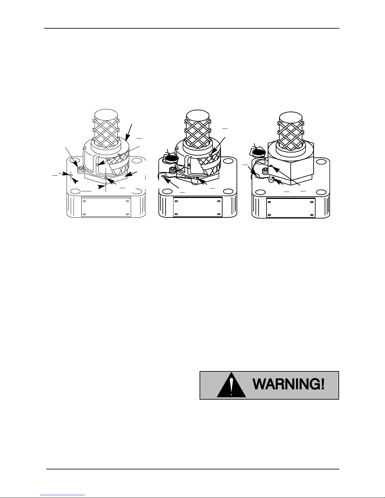
OM-06520SM SERIES
b. Drill a 1/16 inch (1,6 mm) diameter hole (B) in
the cable grip body approximately 45_ coun
terclockwise from hole A in the terminal hous
ing. If the old cable grip is being reused, the
existing hole may be reused if it is in the cor
rect location.
KNURLED AND RIBBED TYPE CABLE GRIP INSTALLATION HEX TYPE
NUT
LOCKING
SETSCREW
A
45_
C
RIBBED NUT
HEX
BODY
1 ”
16
DIA
.
B
FOR
TYP.
A
c. Insert the seal wire (40) through hole B and
equalize the wire length. Twist the wire ends
approximately 10 turns and insert one end of
the wire through hole A. Draw tight and twist
the wire ends approximately 10 turns.
CABLE GRIP INSTALLATION
C
FOR
KNURLED NUT
A
B
B
C
Figure E-4. Safety Seal Installation
d. Make sure the cable grip nut is tight. Drill a
1/16 inch (1,6 mm) diameter hole (C) through
the flange on the cable grip adjacent to hole B
in the hex body.
e. Insert one end of the twisted wire through hole
C and draw tight. Twist the ends two turns and
push them through the lead seal (41).
f. Wrap the ends of the wires once around the.
twisted length from A to C from opposite di
rections, and push the wire ends through the
lead seal again. Clamp the seal to secure the
wire ends.
FINAL ASSEMBLY
(Figure E-1)
If the hoist bail (20) was removed, secure it to the
motor housing with the hardware (10 and 22).
If the discharge flange (9) was removed from the
motor housing, replace the discharge flange gas
ket (8). Apply `Never‐Seez' or equivalent com
pound on the flange studs, and torque the nuts
(10) to 11 ft. lbs. (132 in. lbs. or 1.5 m. kg.).
Connect the discharge hose, and reposition the
pump. If rigid piping or long hose is used, reposi
tion the pump and then connect the piping.
LUBRICATION
Seal Cavity
Check the oil level in the seal cavity before initial
startup, after the first two weeks of operation, and
every month thereafter.
Check the oil level only when the pump
is cool. If the oil level plug is removed
when the pump is hot, pressure in the
seal cavity can cause hot oil to be
ejected as the plug is removed.
To check the seal cavity oil, lay the pump on its side
with the level plug up. Remove the plug, and screw
PAGE E - 18 MAINTENANCE AND REPAIR
Page 49

SM SERIESOM-06520
a short 1/4 inch NPT nipple into the hole. Plug the
the level plug.
open end of the nipple with your finger. Tip the
pump upright, drain off a small amount of oil into a
transparent cup, and lay the pump on its side
again. If the oil level is abnormally low, or the color
When lubricating a dry (overhauled) pump, add
approximately 1 US pint (0,47 liter) of lubricant (see
Table 1 for lubricant specifications).
milky or dark, refer to Draining Oil From Seal
Cavity in this section for instructions and
troubleshooting tips. If the oil is clear, remove the
nipple, top off the seal cavity with oil, and reinstall
The grade of lubricant used is critical to the opera
tion of this pump. Use uninhibited transformer oil
as specified in the following table.
Table E-1. Pump Oil Specifications
Specifications:
Type Premium high viscosity index, anti‐wear hydraulic oil..............................
Viscosity (SSU @ 104_F [40_C]) 110 to 155.........................................
Viscosity (SSU @ 210_F [100_C]) 40 to 50...........................................
Dielectric 26,000 (volts‐min)........................................................
Recommended supplier:
Gulf Oil Company Gulf Harmony AW Hydraulic Fluid MG 32............................
Acceptable alternate suppliers:
Gulf Oil Company Gulf Harmony 32 AW..............................................
Texas Oil Company Rando HD 32 or HD AZ 32........................................
Sun Oil Company Sunvis 816 or 916.................................................
BP (Also Boron) Energol‐HLP 32.....................................................
Shell Oil Company Tellus 32, Tellus T‐23 or T32.......................................
ARCO Duro 32...................................................................
Exxon (Also Esso) Nuto H 32........................................................
Petro‐Canada Harmony HVI 22......................................................
Motor Bearings
The motor bearings are permanently sealed, and
no additional lubrication is required.
MAINTENANCE AND REPAIR PAGE E - 19
Page 50

For U.S. and International Warranty Information,
Please Visit www.grpumps.com/warranty
or call:
U.S.: 419-755-1280
International: +1-419-755-1352
For Canadian Warranty Information,
Please Visit www.grcanada.com/warranty
or call:
519-631-2870
THE GORMAN‐RUPP COMPANY D MANSFIELD, OHIO
GORMAN‐RUPP OF CANADA LIMITED D ST. THOMAS, ONTARIO, CANADA
 Loading...