

Page 1
AC
OM-04136
January 21, 1998
Rev. C 09-03-03
INSTALLATION AND
OPERATION MANUAL
WITH P ARTS LISTS
CONTROL BOXES
MODELS
27515--503 27515--504 27515--505 27515--506
27515--507 27515--513 27515--514 27515--515
27515--516 27515--517 27515--524 27515--525
27515--534 27515--535 27515--543 27515--544
27515--545 27515--546 27515--554 27515--571
27515--572
THE GORMAN-RUPP COMPANY F MANSFIELD, OHIO
GORMAN-RUPP OF CANADA LIMITED D ST. THOMAS, ONTARIO, CANADA Printed in U.S.A.
ECopyright by the Gorman-Rupp Company
Page 2

TABLE OF CONTENTS
INTRODUCTION PAGE I --- 1.................................................
SA FE T Y --- SE C TIO N A PA G E A --- 1...........................................
IN STA L LAT ION --- SEC T IO N B PA G E B --- 1....................................
GENERAL INFORMATION PAGE B --- 1..................................................
PREINSTALLATION INSPECTION PAGE B --- 1............................................
CONTROL BOX INSTALLATION P AGE B --- 1.............................................
Enclosure PA GE B --- 1.............................................................
CONTROL BOX DIMENSIONS PAGE B --- 1..............................................
ELECTRICAL CONNECTIONS PAGE B --- 6...............................................
Grounding Methods PAGE B --- 6....................................................
Field Wiring Connections (Incoming Power) P AGE B --- 7...............................
Pump Motor Voltage Limits PAGE B --- 7..............................................
Power Cable Connections PA GE B --- 7...............................................
Control Box Adjustments PAGE B --- 7................................................
WIRING DIAGRAMS PAGE B --- 8.......................................................
Parts Lists:
Control Boxes 27515---503, 27515---513 And 27515---543 PAGE B --- 8...................
Control Boxes 27515---504, 27515---514 27515---544 And 27515---554 PAGE B --- 11........
Control Boxes 27515---505, 27515---515 And 27515---545 PAGE B --- 13...................
Control Boxes 27515---506, 27515---516 And 27515---546 PAGE B --- 15...................
Control Boxes 27515---507 And 27515---517 PAGE B --- 17...............................
Control Boxes 27515---524 And 27515---534 PAGE B --- 19...............................
Control Boxes 27515---525 And 27515---535 PAGE B --- 21...............................
Control Boxes 27515---571 And 27515---572 PAGE B --- 23...............................
Control Box Da ta Chart PAGE B --- 25.................................................
27515---571 And 27515---572 Control Box Data PAGE B --- 26............................
Control Box Torque Values PAGE B --- 26..............................................
OPER AT IO N --- SE C T IO N C PA G E C --- 1......................................
CONTROL BOX FUNCTION PAGE C --- 1.................................................
Component Function P AGE C --- 1...................................................
TR OUB LES HOO TI NG --- SE CTI ON D PA G E D --- 1..............................
ELECTRICAL TESTING PAGE D --- 2.....................................................
Test Equipment PA GE D --- 2........................................................
Voltage Imbalance PAGE D --- 2.....................................................
i
Page 3

OM--04136 CONTROL BOXES
INTRODUCTION
Read this manual carefully to learn how to safely
install and operate your control box. Failure to do
so couldresult in personal injury or damage to the
control box or the pump.
This manual does not include maintenance instructions. Have a qualified electrician perform all
maintenance. Be sure to follow all safety precautionsas outlinedby the NationalElectric Codeand
all local codes.
Thecontrolboxis arainproof enclosure with apadlockable front cover. The enclosure is not de-
signed to be watertight, and should not be submerged. They are designed for use with 200, 230,
460, 575 or 380 volts, depending on your pump.
The integral electric motor of the submersible
pump must be operated through the control box.
The control box is not explosion-proof and should
not be operated in a hazardous atmosphere.
Because pump installations are seldom identical,
this manual cannot possibly provide detailed instructions and precautions for every aspect of
each specific application. Therefore, it is the responsibility of the owner/installer of the pump to
ensure that applications not addressed in this
manual are performed only after establishing that
neither operator safety norpump integrity are compromised by the installation. Pumps and related
equipment must be installed and operated ac-
cording to all national, local and industry standards.
Ifthereareanyquestionsregardingthecontrolbox
which are not covered in this manual or in other literature accompanying the unit, please contact
your Gorman-Rupp distributor or the GormanRupp Company:
RECORD CONTROL BOX NUMBER
Please record the control box number, voltage,
andphasein thespaces providedbelow.YourGorman-Ruppdistributor needs this informationwhen
you require parts or service.
Control Box:
Voltage:
Phase:
WARRANTY INFORMATION
The warrantyprovided with your control box ispart
ofGorman-Rupp’ssupportprogram for customers
who operate and maintain their equipment as described in this and the other accompanying literature. Please note that should the equipment be
abused or modified to change its performance beyond the original factory specifications, the warranty will become void and any claim will be denied.
The following are used to alert personnelto procedures which require special attention, to those
which could damage equipment, and to those
which could be dangerous to personnel:
Immediate hazards whichWILLresultin
severe personal injury or death. These
instructions describe the procedure required and the injury which will result
from failure to follow the procedure.
The Gorman-Rupp Company
P.O. Box 1217
Mansfield, Ohio 44901--1217
or:
Gorman-Rupp of Canada Limited
70 Burwell Road
St. Thomas, Ontario N5P 3R7
INTRODUCTION
Hazards or unsafe practices which
COULDresult in severe personal injury
or death. These instructions describe
the procedure required and the injury
which could result fromfailure to follow
the procedure.
PAGE I -- 1
Page 4

OM--04136CONTROL BOXES
damage which could result from failure to
follow the procedure.
HazardsorunsafepracticeswhichCOULD
resultinminor personalinjuryorproductor
property damage. These instructions describe the requirements and the possible
NOTE
Instructions to aid in installation, operation, and
maintenance or which clarify a procedure.
PAGE I -- 2
INTRODUCTION
Page 5
SAFETY --- SECTION A
The following information applies
throughout this manual to GormanRupp Control Boxes.
CONTROL BOXESOM--04136
Because pump installationsare seldom
identical, this manual cannot possibly
provide detai led instructions and precautions for each specific application.
Therefore, it is the owner/installer’s responsibility to ensure that applications
not addressed in this manual are performed only after establishing that neither operator safety nor pump integrity
are compromised by the installation.
Before attempting to install, operate, or
wire this control box, familiarize yourself with this manual, and with all other
literature shipped with the control box.
Unfamiliarity with all aspects of control
operation covered in this manual could
lead to destructionof equipment,inj ury,
or death to personnel.
Beforeconnectingany cable to thecontrol box, be sure to ground the control
box. See Section B for suggested
grounding methods.
The electrical power used to operate
thiscontrolbox is highenough tocause
injury or death. Obtain the services of a
qualified electrician to make all electrical connections. Make certain that the
enclosure is properly grounded; never
use gas pipe as an electrical ground.Be
sure that the incoming power matches
the voltage and phase of the control before connecting the power source. Do
not make ele ctrical connections if the
voltage is not within the limits. If the
overload unit is tripped during operation, correct the problem before restarting.
The electrical power used to operate
thiscontrolbox is highenough tocause
injury or death. Make certain that the
control handle on the control box is in
the OFF position and locked out, or that
the power supply to the control box has
been otherwise cut off and locked out,
beforeattempting toopen or service the
control box. Tag electrical circuits to
prevent accidental start-up.
The control box provides overload protection and power control. Do not connect the pump motor directly to the incoming power lines. If the power circuit
breakeror overloadrelayis trippedduring operation, correct the problem before resetting or replacing.
SAFETY
Do not install and operate a non-explosion proof control box in an explosive
atmosphere. Install, connect, and operate the control box in accordance with
MSHA Schedule 2G. If there is a conflict
between the instructions in the manual
accompanying the unit and MSHA,
MSHA shall take precedence. All elec-
PAGE A -- 1
Page 6

OM--04136CONTROL BOXES
tricalequipment supplied with this controlboxconformedtoapplicablefederal
regulations and national codes in effect
on the date of manufacture.
Obtain the services of a qualified electrician to troubleshoot, test and/or ser-
vice the electrical components of this
control box.
Do not attempt to repair individual components of the control box. Any component which fails should be replaced.
PAGE A -- 2
SAFETY
Page 7
INSTALLATION --- SECTION B
GENERAL INFORMATION
Review all SAFETY information in Section A.
CONTROL BOXESOM--04136
Thissection is intended only to summarizerecommendedinstallationpracticesfor the controlbox.If
there are any questions concerning your specific
application,contact your Gorman-Ruppdistributor
or the Gorman-Rupp Company.
PREINSTALLATION INSPECTION
The control box was inspected before shipment
from the factory. Before installation, inspect the
controlfor damage which may have occurred during shipment. Check as follows:
a. Inspect thecontrolbox for cracks, dents, and
other obvious damage.
b. Checkthat allcontrolboxcomponentsarese-
curely attached to their mounting surfaces,
and that the electrical connections are tight
and free of corrosion.
c. Compare the amperes, phase, voltage and
hertzindicatedonthepump motornameplate
to the ratings indicated for the control box.
The control box furnished with the
pump is designed to operate the pump.
The control box provides overload protection and power control. Do not connect the pump motor directly to the incoming power lines.
Enclosure
Thecontrolboxis a NEMA Type3Rrainproofenclosurewithapadlockablefrontcover.Theenclosure
is not designed to be watertight, and should not
be submerged.
No mounting hardware is furnished with the controlbox. Securethe controlbox verticallyon alevel
surface, above flood level. The control should be
mounted on a flat surface. If the mounting surface
is not perfecting flat, it may be necessary to use
shims (not supplied) w ith the enclosure.The box
shouldbeeasilyaccessibleto theoperator, and located close enough to the pump to avoid excessive voltage drop due to cable length.
d. Carefully read all tags, decals, and markings
on the control box.
If anything appears to be abnormal, contact your
Gorman-Rupp distributor or the factory to determinethe repair policy. Do not put the controlbox
into service until appropriate action has been
taken.
CONTROL BOX INSTALLATION
The control box provides protection for the pump
motor against excessive heat due to motor overloads and failure to start, as well as short circuit
protection for incoming power lines.
INSTALLATION
Failure to mount the control box vertically
on a level surface may affect operation of
the pump controls.
Afterthe box issecurely installed, make certain t he
front cover latches properly before installing any
electrical lines.
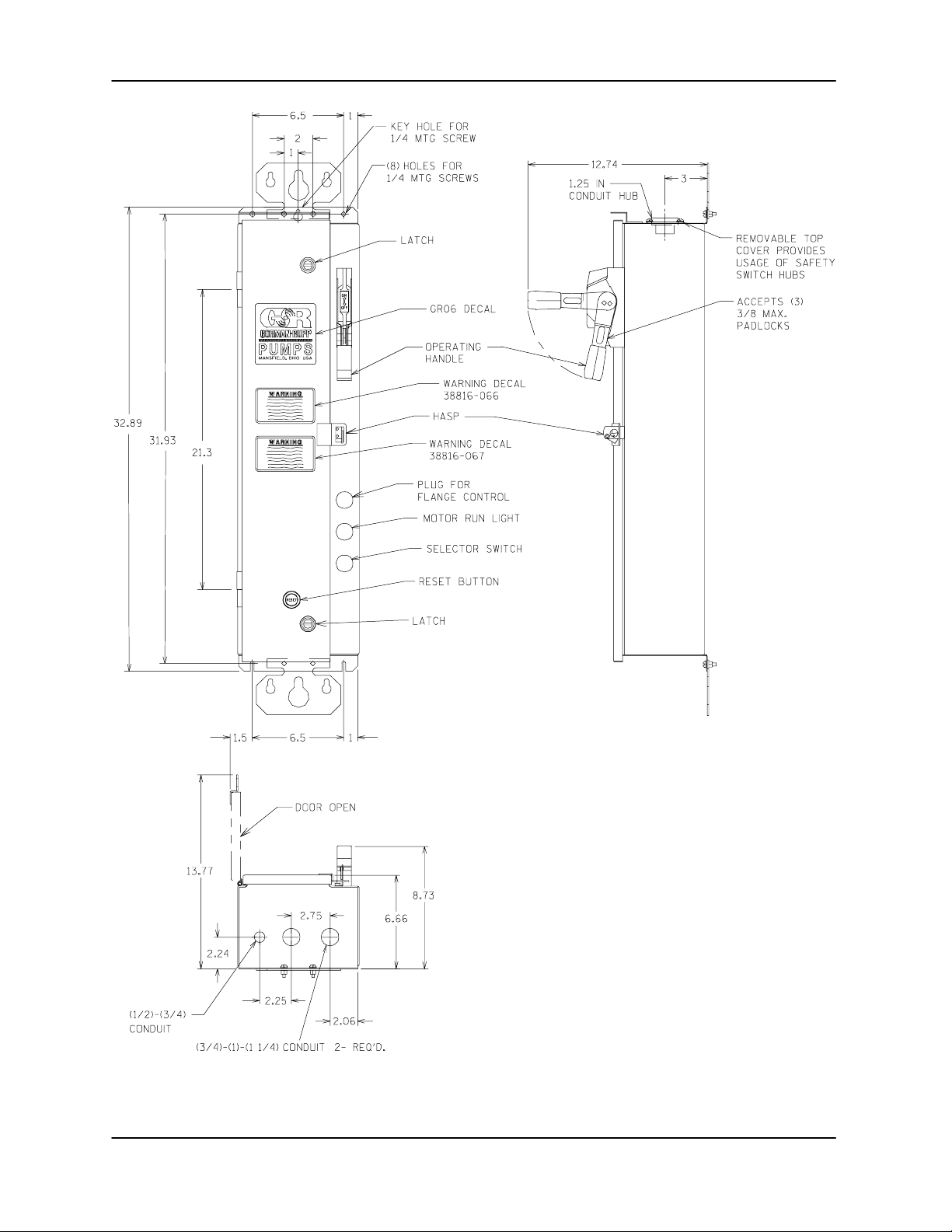
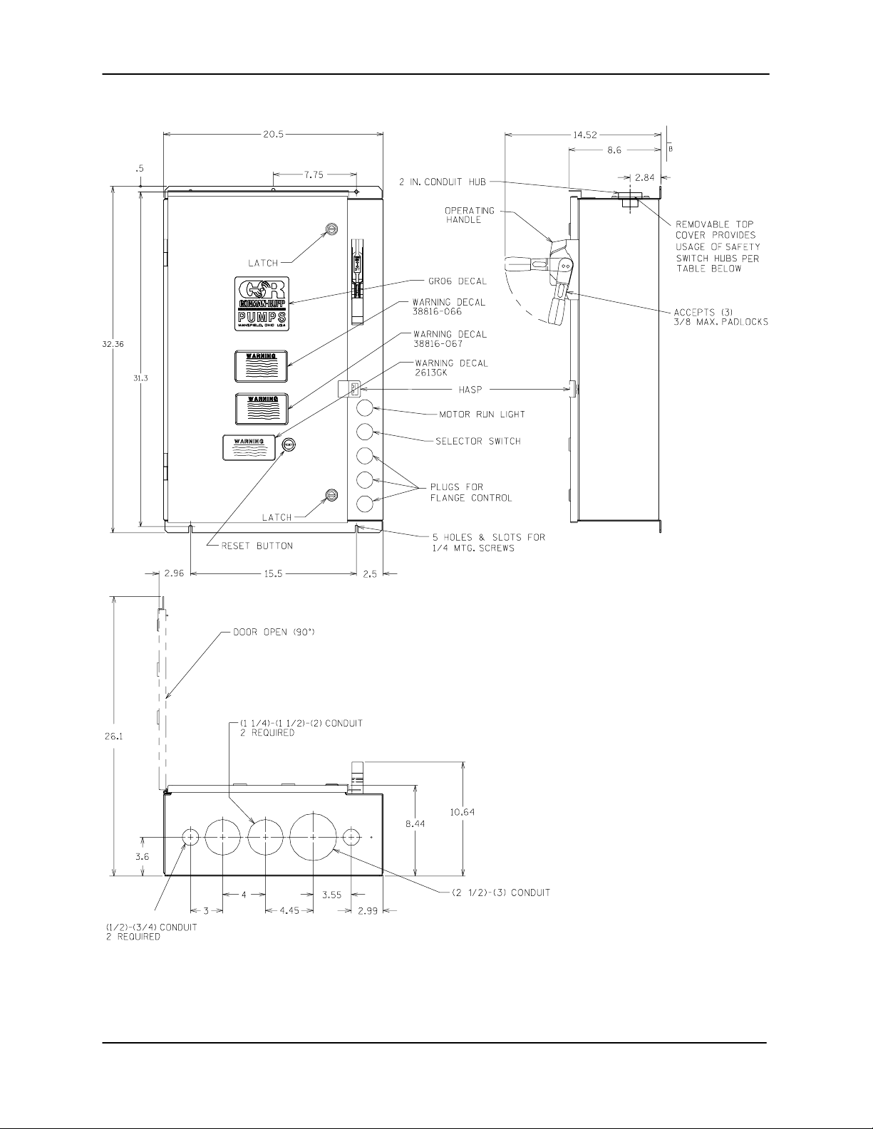
CONTROL BOX DIMENSIONS
For the approximate physical dimensions of your
control box, refer to Figures B --- 1 t hru B --- 4.
PAGE B -- 1
Page 8
OM--04136CONTROL BOXES
Figure B--1. 27515--503, 27515--504, 27515--513, 27515--514, 27515--524, 27515--534,
27515--543, 27515--544 And 27515--554 Control Box Dimensions
PAGE B -- 2
INSTALLATION
Page 9
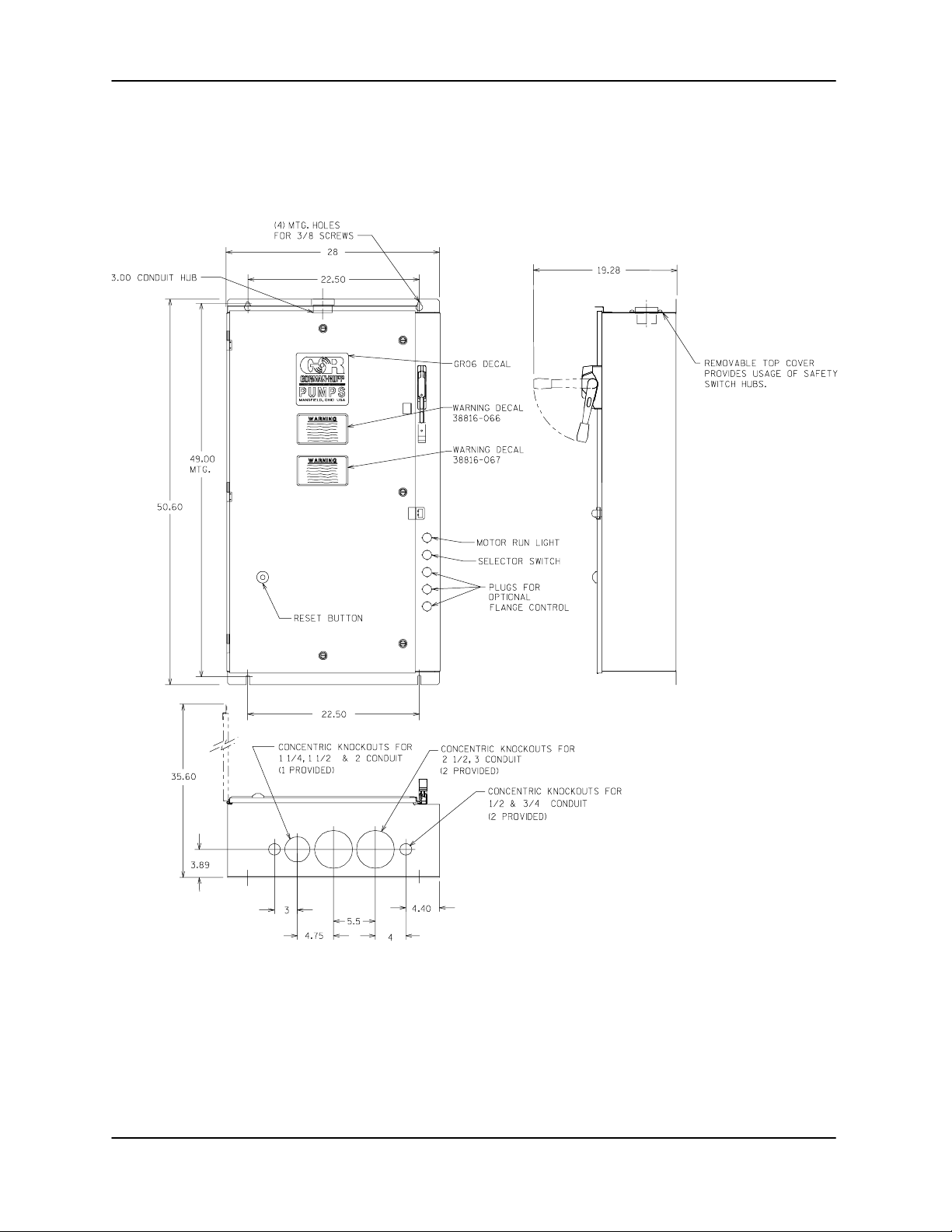
CONTROL BOXESOM--04136
Figure B--2. 27515--505, 27515--506, 27515--515, 27515--516, 27515--525, 27515--535,
27515--545 And 27515--546 Control Box Dimensions
INSTALLATION
PAGE B -- 3
Page 10
OM--04136CONTROL BOXES
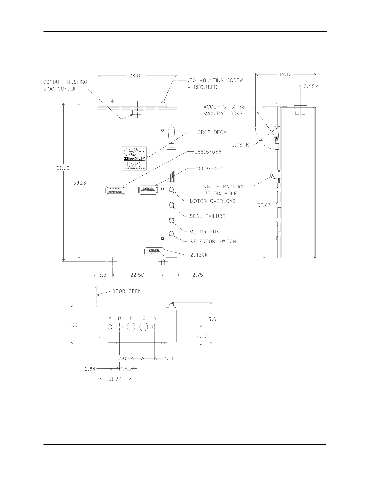
PAGE B -- 4
Figure B--3. 27515--507 And 27515--517 Control Box Dimensions
INSTALLATION
Page 11
CONTROL BOXESOM--04136
INSTALLATION
Figure B--4. 27515--571 And 27515--572 Control Box Dimensions
PAGE B -- 5
Page 12

OM--04136CONTROL BOXES
ELECTRICAL CONNECTIONS
Obtain the services of a qualified electrician to make all electrical connections and to service the control box.
Theelectricalpowerused in thiscontrol
box is high enough to c ause injury or
death. Make certain that the controlbox
is properly grounded after installation.
Make certain that the power source
phase and voltage matches the data on
the control box. Complete all electrical
connections before connecting the
power supply to the control box. Make
certain to ground the appropriate lead
a) PLATE ELECTRODE b) DRIVEN ELECTRODE c) BURIED ELECTRODE
of the power source before connecting
power to the control. Make certain that
the control box is properly grounded after installation.
Grounding Methods
Electricallygroundthe installationbefore connecting the field w iring to the control box. I nstall a
groundingterminaltothe enclosureand connect it
to a properly embedded electrode.
Thematerialusedfortheelectrodemustbe anexcellent conductor of electricity, such as copper. If
ironorsteelis used, it must be galvanizedorotherwise metal plated to resist corrosion. Do not coat
the electrode with any material of poor conductivity, such as paint or plastic.
The electrode must conform to the recommendationsof N.E.C. ARTICLE 250. Followall installation
requirements of the N.E.C., and all applicable
codes. See Figure B---5 for some suggested
grounding methods.
SOIL
1/4 INCH (6,4 MM)
STEEL PLATE 2 SQ.
FEET (1858,1 SQ. CM)
SURFACE AREA
(MINIMUM)
Figure B--5. Suggested Grounding Methods
a. Plate Electrode: An iron or steel plate, 1/ 4
inch (6,4 mm) thick, completely impeded in
the ground. The plate must present a surface
area of at least 2 square feet (1858,1 sq. cm).
b. Driven Electrode: A rod or pipe, 3/4 inch
(19,1mm)indiameterminimum,8feet (2,4m)
long, completely driven into the ground.
c. Buried electrode: If rock or stone prevents
embeddingthe full8 foot (2,4m) length ofthe
ground rod, bury it horizontally in a trench.
PAGE B -- 6
SOIL
3/4 INCH (19,1
MM) NOMINAL
DIAMETER
(MINIMUM)
8 FEET
(2,4 M)
SOIL
ROCK
3/4 INCH ( 19,1 MM)
NOMINAL DIAMETER
(MINIMUM) 8 FEET
(2,4 M) LONG
Space the ground rod or plates at least 6 feet
(1,8 m) from any other electrode or ground
rod, such as those usedfor signal circuits,radio grounds, lightning rods, etc.
Theearthsurroundingthegroundrod or plate
must contain enough moisture to make a
goodelectricalconnection.Indryorsandyareas, pour water around the rod, or consult
qualified personnel to devise a method of improving the connection.
INSTALLATION
Page 13

CONTROL BOXESOM--04136
Field Wiring Connections (Incoming Power)
The electrical power used to operate
this pump is high enough to causeinjury or death. Obtain the services of a qualified electrician to make all electrical
connections. Make certain that the
pump and enclosure are properly
grounded; never use gas pipe as an
electrical ground. Be sure that the incoming power matches the voltage and
phase of the pump and control before
connecting the power source. Do not
run the pump if the voltage is not within
the limits.
The control isdesigned to regulate the power supply. The field wiring must be properly sized to ensure an adequate voltage supply. The voltage
availableatthepumpmotormustbe withinthe indicated range.
Table 1. Pump Motor Voltage Limits
Nominal
Voltage
200 3 180 220
230 3 210 250
380 (50 Hz) 3 350 420
460 3 420 500
575 3 520 630
Phase
Minimum
Voltage
Maximum
Voltage
Power Cable Connections
Theelectricalpowerusedtooperatethe
control box is high enough to cause injury or death. Obtain the services of a
qualified electrician to make all electrical connections. Make certain
comingpowertothecontrolboxisin
that in-
the
off position and locked out, or that the
power supply to the control box has
been otherwise cut off and locked out
before connecting power or accessory
cables.
When necessary to change or connect power
cables to the control box, make certain the incomingpower is OFF and LOCKED OUT.Makecertain
the control box is properly grounded and that the
electrical data on the control matches the pump
motor name plate data.
Connect the power cable to the control box as
shown in the wiring diagrams in this section or inside the control box door. Use conduit or cable
clampsto secure the power and accessorycables
to the control box. Make certain that all connections are tight a nd that cable entry points are
rainproof.
Control Box Adjustments
For control adjustments and settings, refer to the
information inside the control box door.
,
Ifthe voltage isnot withinthe recommendedlimits,
obtain the services of a qualified electrician to determine the correct field wiring size and other details to ensure an adequate voltage supply.
Make certain all connections are tight and that cable entry points are rainproof. Support the cable
weight, if required, to prevent excessive strain on
cable clamps and cable.
NOTE
After the power cables havebeen connected to the
control box, make certain the connection is waterproof.
INSTALLATION
To maintain overcurrent, short circuit
and ground fault protection, the manufacturer’s instructions for selection of
the heater pack and setting of the instantaneous trip circuitbreaker (current
interrupter) or control interface module
mustbefollowed.Failureto followthese
instructionscan resultin damage tothe
pump and/or serious injury to personnel.
PAGE B -- 7
Page 14

CONTROL BOXES OM--04136
Figure B--8. Control Boxes 27515--285 And 27515--286 Pictorial Diagram
For specific control box data information, refer to
the chart at the end of this section.
PAGE B -- 8
INSTALLATION
Page 15

OM--04136 CONTROL BOXES
Figure B--9. Control Boxes 27515--503, 27515--513 And 27515--543 Elementary Wiring Diagram
REPAIR PARTS LIST
ITEM
NO.
10 “MOTOR RUN” LEGEND PLATE10250TM81 1
PART NAME C H PART
NUMBER
1 CIRCUIT BREAKER 30 AMPS HMCP030H1C 1
2 MOTOR STARTER AN16DNOAB 1
3 CONTACTOR --- 3 POLE CN15DN3AB 1
4 RENEWAL CONTACT SET 6---65---2 1
5 COIL 9---2703---1 1
6 OVERLOAD RELAY C306GN3B 1
7 HEATER PACK SEE CHART AT END OF THIS SECTION
8 CONTROL TRANSFORMER C0100G6UFB 1
9 “MOTOR RUN” PILOT LIGHT 10250T34G 1
QTY ITEM
INSTALLATION
PART NAME C H PART
NO.
11 TERMINAL BLOCK 80---5817 2
12 H---O---A SELECTOR SWITCH 10250T21KB 1
13 “HAND-OFF-AUTO” LGND PLT 10250TM51 1
14 OPT LIQ LVL CONTROL RELAY A999AY574 1
15 S ECO N DA RY FUSE 44 --- 79 6 --- 5 1
16 PRIMARY FUSE --- 380V 44-- -2144---17 2
17 PRIMARY FUSE --- 460V 44-- -2144---13 2
18 PRIMARY FUSE --- 575V 44-- -2144---12 2
19 RESET BOOT 35---524 2
20 PUB SHEET 25762 2
NUMBER
PAGE B -- 9
QTY
Page 16

CONTROL BOXES OM--04136
Figure B--10. Control Boxes 27515--503, 27515--513 And 27515--543 Pictorial Diagram
For specific control box data information, refer to
the chart at the end of this section.
PAGE B -- 10
INSTALLATION
Page 17

OM--04136 CONTROL BOXES
Figure B--11. Control Boxes 27515--504, 27515--514, 27515--544 And 27515--554
Elementary Wiring Diagram
REPAIR PARTS LIST
ITEM
NO.
10 “MTR RUN” LEGEND PLATE 10250TM81 1
11 TERMINAL BLOCK 80-- -5817 2
PART NAME C H PART
NUMBER
1 CIRCUIT BREAKER 50 AMPS HMCP050K2C 1
2 MOTOR STARTER AN16GNOAB 1
3 CONTACTOR --- 3 POLE CN15DN3AB 1
4 RENEWAL CONTACT SET 6---65---8 1
5 COIL 9---2703---1 1
6 OVERLOAD RELAY C306GN3B 1
7 HEATER PACK (SEE CHART AT END OF THIS SECTION)
8 CONTROL TRANSFORMER C0100G6UFB 1
9 “MTR RUN” PILOTLIGHT 10250T34G 1
INSTALLATION
QTY ITEM
NO.
12 H---O---A SELECTR SWITCH 10250T21KB 1
13 “H-O-A” LEGEND PLATE 10250TM51 1
14 OPTL FLOAT CNTRL RELAY A999AY574 1
15 SE CONDAR Y F USE 44 --- 79 6 --- 5 1
16 PRIMARY FUSE 575V 44---2144---12 2
17 PRIMARY FUSE 460V 44---2144---13 2
18 PRIMARY FUSE 380V 44---2144---17 2
19 PRIMARY FUSE 230V 44---2144---20 2
20 PRIMARY FUSE 200V 44---2144---22 2
21 RESET BOOT 35---524 1
22 PUB SHEET 25762 1
PART NAME C H PART
NUMBER
QTY
PAGE B -- 11
Page 18

CONTROL BOXES OM--04136
FigureB--12. ControlBoxes27515--504,27515--514, 27515--544 And27515--554 PictorialD iagram
For specific control box data information, refer to
the chart at the end of this section.
PAGE B -- 12
INSTALLATION
Page 19

OM--04136 CONTROL BOXES
Figure B--13. Control Boxes 27515--505, 27515-- 515 And 27515--545 Elementary Wiring Diagram
REPAIR PARTS LIST
ITEM
NO.
10 “MOTOR RUN” LEGEND PLATE10250TM81 1
11 TERMINAL BLOCK 80---5817 3
PART NAME C H PART
NUMBER
1 CIRCUIT BREAKER 100 AMPS HMCP100R3 1
2 MOTOR STARTER AN16KNOA 1
3 CONTACTOR --- 3 POLE CN15KN3A 1
4 RENEWAL CONTACT SET 6---43---2 1
5 COIL (ON COIL) 1
6 OVERLOAD RELAY C306KN3 1
7 HEATER PACK (SEE CHART AT END OF THIS SECTION) 1
8 CONTROL TRANSFORMER C0250G6UFB 1
9 MOTOR RUN” PILOT LIGHT 10250T34G 1
INSTALLATION
QTY ITEM
NO.
12 H---O---A SELECTOR SWITCH 10250T21KB 1
13 “H-O-A” LEGEND PLATE 10250TM5 1
14 230V PRIMARY FUSE 44---2144---29 2
15 380V PRIMARY FUSE 44---2144---26 2
16 460V PRIMARY FUSE 44---2144---23 2
17 575V PRIMARY FUSE 44---2144---21 2
18 S ECO N DA RY FUSE 44 --- 44 --- 796 --- 1 0 1
19 RESET BOOT 32---524 1
20 OPTL FLOAT CONTROL RELAY A999AY574 1
21 PUB SHEET 25773 1
PART NAME C H PART
NUMBER
PAGE B -- 13
QTY
Page 20

CONTROL BOXES OM--04136
Figure B--14. Control Boxes 27515--505, 27515--515 And 27515--545 Pictorial Diagram
For specific control box data information, refer to
the chart at the end of this section.
PAGE B -- 14
INSTALLATION
Page 21

OM--04136 CONTROL BOXES
Figure B--15. Control Boxes 27515--506, 27515-- 516 And 27515--546
Elementary Wiring Diagram
REPAIR PARTS LIST
ITEM
NO.
10 “MOTOR RUN” LEGEND PLATE10250TM81 1
11 TERMINAL BLOCK 80---5817 2
PART NAME C H PART
NUMBER
1 CIRCUIT BREAKER, 150 AMPS HMCP150T4C 1
2 MOTOR STARTER AN16NNOA 1
3 CONTACTOR --- 3 POLE CN15NN3A 1
4 RENEWAL CONTACT SET 6---44---2 1
5 COIL (ON COIL) 1
6 OVERLOAD RELAY C306NN3 1
7 HEATER PACK SEE CHART AT END OF THIS SECTION
8 CNTRL TRANSFORMER C0250G6UFB 1
9 “MOTOR RUN” PILOT LIGHT 10250T34G 1
INSTALLATION
QTY ITEM
NO.
12 H---O---A SELECTOR SWITCH 10250T21KB 1
13 “H-O-A” LEGEND PLATE 10250TM51 1
14 RESET BOOT 32---524 1
15 OPT’L FLOAT CNTROL RELAY A999AY524 1
16 PRIMARY FUSE, 200V 44---2144---31 2
17 PRIMARY FUSE, 230V 44---2144---29 2
18 PRIMARY FUSE, 380V 44---2144---26 2
19 PRIMARY FUSE, 460V 44---2144---23 2
20 PRIMARY FUSE, 575V 44---2144---21 2
21 SECONDARY FUSE 44---796---10 1
22 PUB SHEET 25775 1
PART NAME C H PART
NUMBER
QTY
PAGE B -- 15
Page 22

CONTROL BOXES OM--04136
Figure B--16. Control Boxes 27515--506, 27515--516 And 27515--546 Pictorial Diagram
For specific control box data information, refer to
the chart at the end of this section.
PAGE B -- 16
INSTALLATION
Page 23

CONTROL BOXESOM--04136
Figure B--17. Control Boxes 27515--507 And 27515--517 Elementary Wiring Diagram
REPAIR PARTS LIST
ITEM
NO.
10 “MOTOR RUN” LEGEND PLATE10250TM81 1
11 TERMINAL BLOCK 80---5817 2
PART NAME C H PART
NUMBER
1 CIRCUIT BREAKER, 250 AMPS HMCP250W5C 1
2 MOTOR STARTER AN16SNOAB 1
3 CONTACTOR --- 3 POLE CN15SN3AB 1
4 RENEWAL CONTACT SET 6---45---2 1
5 COIL (ON COIL) 1
6 OVERLOAD RELAY C306DN3 1
7 HEATER PACK SEE CHART AT END OF THIS SECTION
8 CONTROL TRANSFORMER C0250G6UFB 1
9 “MOTOR RUN” PILOT LIGHT 10250T34G 1
INSTALLATION
QTY ITEM
NO.
12 H---O---A SELECTOR SWITCH 10250T21KB 1
13 “H-O-A” LEGEND PLATE 10250TM51 1
14 CURRENT TRANSFORMER 42---3564---2 1
15 RESET BOOT 32---524 1
16 OPT’L FLOAT CNTROL RELAY A999AY574 1
17 PRIMARY FUSE, 460V 44---2144---23 2
18 PRIMARY FUSE, 575V 44---2144---21 2
19 SECONDARY FUSE 44---796---10 2
20 PUB SHEET 25775 2
21 OVERLOAD RELAY ADAPTER 10---6380---2 1
PART NAME C H PART
NUMBER
QTY
PAGE B -- 17
Page 24

OM--04136CONTROL BOXES
Figure B--18. Control Boxes 27515--507 And 27515--517 Pictorial Diagram
For specific control box data information, refer to
the chart at the end of this section.
PAGE B -- 18
INSTALLATION
Page 25

CONTROL BOXESOM--04136
Figure B--19. Control Boxes 27515--524 And 27515--534 Elementary Wiring Diagram
REPAIR PARTS LIST
ITEM
NO.
10 “MOTOR RUN” LEGEND PLATE10250TM81 1
PART NAME C H PART
NUMBER
1 CIRCUIT BREAKER --- 50 AMPS HMCP050K2C 1
2 MOTOR STARTER AN16DNOAB 1
3 CONTACTOR --- 3 POLE CN15GN3AB 1
4 RENEWAL CONTACT SET 6---65---8 1
5 COIL 9---2703---1 1
6 OVERLOAD RELAY C306GN3B 1
7 HEATER PACK SEE CHART AT END OF THIS SECTION
8 CONTROL TRANSFORMER C0100G6UFB 1
9 “MOTOR RUN” PILOT LIGHT 10250T34G 1
INSTALLATION
QTY ITEM
NO.
11 TERMINAL BLOCK 80---5817 2
12 H---O---A SELECTOR SWITCH 10250T21KB 1
13 “H-O-A” LEGEND PLATE 10250TM51 1
14 OPT’L FLOAT CNTROL RELAY A999AY574 1
15 S ECO N DA RY FUSE 44 --- 79 6 --- 5 1
16 PRIMARY FUSE, 460V 44---2144---13 2
17 PRIMARY FUSE, 575V 44---2144---12 2
18 RESET BOOT 35---524 1
19 PUB SHEET 25763 1
PART NAME C H PART
NUMBER
QTY
PAGE B -- 19
Page 26

OM--04136CONTROL BOXES
Figure B--20. Control Boxes 27515--524 And 27515--534 Pictorial Diagram
For specific control box data information, refer to
the chart at the end of this section.
PAGE B -- 20
INSTALLATION
Page 27

CONTROL BOXESOM--04136
Figure B--21. Control Boxes 27515--525 And 27515--535 Elementary Wiring Diagram
REPAIR PARTS LIST
ITEM
NO.
10 “MOTOR RUN” LEGEND PLATE10250TM81 1
PART NAME C H PART
NUMBER
1 CIRCUIT BREAKER, 100 AMPS HMCP100R3C 1
2 MOTOR STARTER AN16DNOA 1
3 CONTACTOR --- 3 POLE CN15GN3A 1
4 RENEWAL CONTACT SET 6---43---2 1
5 COIL (ON COIL) 1
6 OVERLOAD RELAY C306KN3 1
7 HEATER PACK SEE CHART AT END OF THIS SECTION
8 CONTROL TRANSFORMER C0250G6UFB 1
9 “MOTOR RUN” PILOT LIGHT 10250T34G 1
INSTALLATION
QTY ITEM
NO.
11 TERMINAL BLOCK 80---5817 2
12 H---O---A SELECTOR SWITCH 10250T21KB 1
13 “H-O-A” LEGEND PLATE 10250TM51 1
14 OPT’L FLOAT CNTROL RELAY A999AY574 1
15 S ECO N DA RY FUSE 44 --- 79 6 --- 5 1
16 PRIMARY FUSE, 460V 44---2144---13 2
17 PRIMARY FUSE, 575V 44---2144---12 2
18 RESET BOOT 35---524 1
19 PUB SHEET 25774 1
PART NAME C H PART
NUMBER
QTY
PAGE B -- 21
Page 28

OM--04136CONTROL BOXES
Figure B--22. Control Boxes 27515--525 And 27515--535 Pictorial Diagram
For specific control box data information, refer to
the chart at the end of this section.
PAGE B -- 22
INSTALLATION
Page 29

CONTROL BOXESOM--04136
Figure B--23. Control Boxes 27515--571 And 27515--572 Elementary Wiring Diagram
REPAIR PARTS LIST
ITEM
NO.
1 CIRCUIT BREAKER (460V) HMCP600L6W 1
2 IT STARTER S801V65P3S 1
3 HEATER ELEMENT 0T---815---120 2
4 SELECTOR SWITCH 10250T21KB 1
5 PILOT LIGHT 10250T181 3
PART NAME C H PART
NUMBER
CIRCUIT BREAKER (575V) HMCP400X5C 1
POWER SUPPLY PSS55A 1
COVER BOOT 32---524 2
CONTACT BLOCK 10250T2 1
QTY ITEM
INSTALLATION
PART NAME C H PART
NO.
RED LENS 10250TC1N 1
GREEN LENS 10250TC2N 1
AMBER LENS 10250TC19N 1
6 CONT TRANSFORMER C0350G6UFB 1
7 WARRICK CONTROL 1D1ED W/5182 RECTIFIER 1
8 TRANS CONT CIRCUIT 44---2144---24 (3A BUSMAN) 2
SE C. FUSES 44 --- 79 6 --- 1 1 (5A BU SMAN) 1
9 CONTROL RELAY D15CR22AB 1
NUMBER
QTY
PAGE B -- 23
Page 30

OM--04136CONTROL BOXES
Figure B--24. Control Boxes 27515--571 And 27515--572 Pictorial Diagram
For specific control box data information, refer to
the chart at the end of this section.
PAGE B -- 24
INSTALLATION
Page 31

Table 2. Control Box Data Chart
CONTROL BOXESOM--04136
PUMP DATA**
V HP Hz FLA
200 10 60 39 554 A999AY523--15 2 45AMPS 208 H2115B-3 C+1/2 28.3/41.3 C0100G6UFB 27521-321
10 60 34 504 A999AY523--9 2 45 AMPS 207 H2114B-3 C 23.5/34.8 C0100G6UFB 27521-321
25 60 60 505 A999AY524--2 3 90 AMPS 210 H2021--3 C 45.7/62.1 C0250G6UFB 27521-321
230
35 60 80 505 A999AY524--2 3 90 AMPS 211 H2022-3 C 62.2/84.6 C0250G6UFB 27521-321
50 60 124 506 A999AY525--2 4 135 AMPS 213 H2024-3 B 106.0/144.0 C0250G6UFB 27521-321
60 60 130 506 A999AY525--2 4 135 AMPS 213 H2024-3 B 106.0/144.0 C0250G6UFB 27521-321
6.7kw 50 11.5 543 A999AY523-- 8 1 27 AMPS 204 H2111B-3 B 9.60/14.4 C0100G6UFB 27521-321
12kw 50 21 544 A999AY523--11 2 45AMPS 205 H2112B-3 C 14.4/23.8 C0100G6UFB 27521-321
15kw 50 28 544 A999AY523--11 2 45AMPS 207 H2114B-3 B 23.5/34.8 C0100G6UFB 27521-321
25kw 50 46 545 A999AY524-- 4 3 90 AMPS 210 H2021-3 A 45.7/62.1 C0250G 6UFB 27521-321
26kw 50 47 545 A999AY524-- 4 3 90 AMPS 210 H2021-3 A 45.7/62.1 C0250G 6UFB 27521-321
380
41kw 50 76 545 A999AY524-- 4 3 90 AMPS 211 H2022-3 B 62.2/84.6 C0250G 6UFB 27521-321
44kw 50 82 545 A999AY524-- 4 3 90 AMPS 211 H2022-3 C 62.2/84.6 C0250G6UFB 27521-321
51kw 50 96 546 A999AY525-- 4 4 135 AMPS 212 H2023-3 B 84.7/115.0 C0250G6UFB 27521-321
65kw 50 115 546 A999AY525--4 4 135 AMPS 213 H2024-3 A 106.0/144.0 C0250G6UFB 27521-321
10 60 17 503 A999AY523-6 1 27 AMPS 205 H2112B-3 B 14.4/23.8 C0100G6UFB 27521-321
15 60 17 524 A999AY523-12 2 45 AMPS 205 H2112B-3 B 14.4/23.8 C0100G6UFB 27521-321
20 60 26 524 A999AY523-12 2 45 AMPS 206 H2113B-3 B 18.7/28.1 C0100G6UFB 27521-321
25 60 30 504 A999AY523--9 2 45 AMPS 206 H2113B-3 C 18.7/28.1 C0100G6UFB 27521-321
30 60 38.5 524 A999AY523-2 2 45 AMPS 208 H2115B-3 B 28.3/41.3 C0100G6UFB 27521-321
35 60 40 504 A999AY523--9 2 45 AMPS 208 H2115B-3 B 28.3/41.3 C0100G6UFB 27521-321
460
50 60 62 505 A999AY524--2 3 90 AMPS 210 H2021-3 C 45.7/62.1 C0250G6UFB 27521-321
60 60 65 505 A999AY524--2 3 90 AMPS 211 H2022-3 A 62.2/84.6 C0250G6UFB 27521-321
60 60 66 525 A999AY524-6 3 90 AMPS 211 H2022-3 A 62.2/84.6 C0250G6UFB 27521-321
95 60 105 506 A999AY525--2 4 135 AMPS 212 H2023-3 C 84.7/115.0 C0250G6UFB 27521-321
100 60 125 506 A999AY525--2 4 135 AMPS 213 H2024-3 B 106.0/144.0 C0250G6UFB 27521-321
140 60 165 507 A999AY567--5 5 270 AMPS 220 H2107B-3 A 2.30/3.77* C0250G6UFB 27521-321
G-RP/N
27515-
CONTROL BOX DATA
CONTROL P/N HEATERPACK NO.
C.H.P/N
A999AY523
NEMA
SIZE
CONT.
CURRENT
RATING
HEATERPACK REFERENCE DATA
G-RP/N
27521-
C-H.
P/N
HEATER
SETTING
RANGE
(AMPS)
CONTROL
TRANS-
FORMER
C-H.
PARTNO.
OPTIONAL
LIQ. LEVEL
CONTROL
RELAY
10 60 13.6 513 A999AY523--7 1 27AMPS 204 H2111B-3 C 9.60/14.4 C0100G6UFB 27521-321
15 60 14.4 534 A999AY523--13 2 45AMPS 204 H2111B-3 C 9.60/14.4 C0100G6UFB 27521--321
20 60 20.8 534 A999AY523--13 2 45AMPS 205 H2112B-3 B 14.4/23.8 C0100G6UFB 27521-321
25 60 24 514 A999AY523--10 2 45AMPS 206 H2113B-3 B 18.7/28.1 C0100G6UFB 27521-321
30 60 30.8 534 A999AY523--13 2 45AMPS 207 H2114B-3 C/B 23.5/34.8 C0100G6UFB 27521-321
35 60 32 514 A999AY523--10 2 45AMPS 207 H2114B-3 B 23.5/34.8 C0100G6UFB 27521-321
575
50 60 50 515 A999AY524--3 3 90 AMPS 210 H2021-3 A 45.7/62.1 C0250G6UFB 27521-321
60 60 52 515 A999AY524--3 3 90 AMPS 210 H2021-3 B 45.7/62.1 C0250G6UFB 27521-321
60 60 52.8 535 A999AY524--7 3 90 AMPS 210 H2021-3 B 45.7/62.1 C0250G6UFB 27521-321
95 60 84 516 A999AY525--3 4 135 AMPS 211 H2022-3 C 62.2/84.6 C0250G6UFB 27521-321
100 60 100 516 A999AY525--3 4 135 AMPS 212 H2023-3 B 84.7/115.0 C0250G6UFB 27521-321
140 60 132 517 A999AY567--6 5 270 AMPS 219 H2106B-3 A 1.92/3.15* C0250G6UFB 27521-321
* CURRENT TRANSFORMER 300:5
** CONSULT INDIVIDUAL PUMP NAME PLATEFOR SPECIFICATIONS.
SEETABLE2FOR 27515--571 AND 27515--572 CONTROL BOX DATA.
INSTALLATION
PAGE B -- 25
Page 32

Table 3. 27515--571 And 27515--572 Control Bo x Data
OM--04136CONTROL BOXES
PUMP DATA**
V HP Hz FLA
275 60 320 571 84--29709--3 5 600 EMA72 A+7/8 C+1/2 3200 STANDARD
460
575
275 60 256 572 84--29709--4 5 400 EMA72 A+1/3 C+1/2 2625 STANDARD
** CONSULT INDIVIDUAL PUMP NAME PLATEFOR SPECIFICATIONS.
G-RP/N
27515-
CONTROL BOX DATA
CONTROL P/N
C.H.P/N
A999AY523
NEMA
SIZE
CONT.
CURRENT
RATING
CONTROL
INTERFACE
MODULE
C.H.
PARTNO.
SETTING
LOCKING PIN
BREAKER
SETTING
CIRCUIT
DIAL & T RIP
SETTING
Table 4. Control Box Torque Values
POWER TERMINATIONS
NEMA
SIZE
1&2
HEATER PACK
MOUNTING SCREW
RECOMMENDED TORQUE
In.lbs.(m.kg.)
9 (0,10)
LINE SIDE LOAD SIDE
Terminal
Wire Size
(AWG)
Torque
In. lbs. (m. kg.)
Wire Size
(AWG)
Use 60/75_CAlor
Cu Conductors
14 --- 10
8
35 (0,40)
40 (0,46)
14 --- 10
Terminal
Torque
In.lbs.(m.kg.)
Use 60/75_CAlor
Cu Conductors
35 (0,40)
8
40 (0,46)
6 --- 4 45 (0,52) 6 --- 4 45 (0,52)
3 --- 2 50 (0,58)
LIQ. LEVEL
CONTROL
RELAY
3
24 --- 30 (0,28 --- 0,35)
4 24 --- 30 (0,28 --- 0,35)
5 9 (0,10)
Use 75_CAlor
Cu Conductors
14 --- 10
8
35 (0,40)
40 (0,46)
6 --- 4 45 (0,52)
3 --- 1/0 50 (0,58)
Use 75_CCu
Conductors Only
14 --- 10
8
35 (0,40)
40 (0,46)
6 --- 4 45 (0,52)
3 --- 1/0 50 (0,58)
Use75_CCopperorAlumi-
num Conductors only.
Torque terminals to values
given on HMCP nameplate.
Use 75_CAlor
Cu Conductors
14 --- 10
8
35 (0,40)
40 (0,46)
6 --- 4 45 (0,52)
3 --- 1/0 50 (0,58)
Use 75_CCu
Conductors Only
Socket Size
In. (mm)
3/16 (4,76)
1/4 (6,35)
5/16 (7,94)
3/8 (9,53)
120 (1,38)
200 (2,30)
250 (2,88)
550 (6,34)
Use75_CCopperorAluminum Conductors only.
550 (6,34)
PAGE B -- 26
INSTALLATION
Page 33

OM--04136
OPERATION --- SECTION C
Review all SAFETY information in Section A.
Follow the instructions on all tags, labels and
decals attached to the control box.
The electrical power used to operate
thiscontrolbox is highenough tocause
injury or death. Make certain that the
control handle on the control box is in
the OFF position and locked out, or that
the power supply to the control box has
been otherwise cut off and locked out,
beforeattempting toopen or service the
control box. Tag electrical circuits to
prevent accidental start-up.
CONTROL BOXES
The control box provides overload protection and power control. Do not connect the pump motor directly to the incoming power lines.
Since operation of the pump motor is dependentuponthequalityandperformance
oftheelectrical controls,thepumpwarranty is valid only when controls have been
specified or provided by The GormanRupp Company .
Component Function
Obtain the services of a qualified electrician to make all electrical connections, and to troubleshoot, test and/or
servicetheelectricalcomponentsofthe
control box.
CONTROL BOX FUNCTION
Thecontrol box isnotdesignedtobeexplosion-proof. Do not operate in an explosive atmosphere.
Thecontrolbox isprovided tofacilitate operationof
thepump.Itcontainscontrolsforstartingandstopping the pump, and provides overload protection
for the pump motor. The pump control may be
equipped with an optional automatic liquid level
sensing device, in which case the low voltage circuits are also contained within the control box.
The control box contains the following hand-operated switches and controls:
D The control handle operates the control
boxcircuit breakers. In theOFF position, the
controlhandle opens the circuit breakers to
interrupt incoming power through the control box and prevent pump operation. In the
ON position, it closes the circuit breakers to
permit pump operation.The circuit breakers
will open or “trip” automatically in the event
of a short circuit overload current. When
tripped,movethecontrolhandletoOFFand
back to ON to reset the circuit breakers.
D The selector switch controls the mode of
operation.Inthe OFFposition,it preventsall
operationofthepump.IntheHANDposition, it a llows the pump to run continuously.
In the AUTO position, it allows the pump to
be controlled automatically by the optional
liquid level control system, if used.
D The reset pushbuttonresets the motorover-
load after it has been TRIPPED by an overload. Theoverloadrelay willtripautomaticallyif the current drawn by the motor exceeds
design specifications. Allow 10 seconds for
OPERATION PAGE C -- 1
Page 34

CONTROL BOXES
OM--04136
the relay to cool after tripping before pressing the reset.
If replacing the heater pack press the reset
button to set relay.
NOTE
If the circuit breaker trips, do not reset it immediately. Wait at least ten minutes before resetting the
control handle back to the ON position. If the overloadunitcontinues totrip, operational problems exist.
The pump motor will restart as soon as
the RESET pushbutton is pressed, unlessthe selectorswitch isintheOFF position. T urn the selector switch to OFF
and move the control handle to OFF before approaching the pump.
D The liquid level devices (optional equip-
ment) operate in conjunction with the 3-position switch (HAND-OFF-AUTO) supplied
as part of that option. After the level sensors
and circuitry have been installed, pump operation may be automatically controlled for
filling or dewatering functions (see LIQUID
LEVEL DEVICES,SectionB).
D The operational warning lights operate in
conjunction with the 3-position switch
(HAND-OFF-AUTO) supplied as a part of
that option. After the level sensors and circuitry have been installed, pump operations
may be automatically controlled for filling or
dewatering functions.
The green run light is standard equipment
onallthe controlsand indicatesthe pumpis
running. The light will be energized when
the3-positionswitchisintheHANDposition
orwhen the pump is running with the switch
in the AUTO position.
The red motor overheat light (standard
equipment only on some controls) works in
conjunction with a thermostat embedded in
the motor windings. In event of a high temperature condition, the motor is shut-down.
Afterthemotorcools,thedeviceisautomatically reset.
Theamberseal failurelight(standardequipment only on some controls) works in conjunction with a sensor probe located in the
sealoilcavityofthepump anddetects aninflux of moisture into the cavity. Should this
condition occur,the pump motor should remain inoperative until the problem is corrected.
Always terminate incoming power to the control
boxbefore investigatingcontrolbox circuitryproblems.
Always terminate power to the control
box before performing service functions.
Power through the control box may be terminated
by moving the control handle to the OFF position,
thereby opening the circuit breakers. This stops
thepump, butdoes notterminate incomingpower
through the field wiring connected to the control
box.
OPERATIONPAGE C -- 2
Page 35

OM--04136
CONTROL BOXES
TROUBLESHOOTING --- SECTION D
Review all SAFETY information in Section A.
The electrical power used to operate
thiscontrol box is high enoughto cause
injury or death. Obtain the services of a
qualified electrician to troubleshoot,
testand/orservice the electricalcomponents.
Manyofthe probableremedieslistedin thetroubleshootingchart below requireuse ofelectrical test instruments; for specific procedures, see Electrical T esting at the end of the troubleshooting chart.
When troubleshooting, also refer tothe technicalinformationaccompanyingthe pumpand optionalequipment.
TROUBLE POSSIBLE CAUSE PROBABLE REMEDY
PUMP FAILS TO
START, OVERLOAD
UNIT NOT TRIPPED
(MANUAL MODE)
OVERLOAD UNIT
TRIPS
Power source incompatible with control Correct power source.
box.
No voltage at line side of circuit beaker. Check power source for blown fuse,
open overload unit, broken lead, or
loose connection.
No voltage at line terminals on bottom Check power source for blown fuse,
of overload unit in control box. open disconnect, broken wire, or
loose connection.
Low or high voltage, or excessive volt- Measure voltage at control box.
age drop between pump and control Check that wiringiscorrect type, size,
box. and length. (See Field Wiring
Connections,SectionB).
Power input phases not If imbalance exceeds 1 percent,
balanced. notify power company
Control box not compatible with pump. Electrical data on control box and
pump name plate must agree. Replace control box if not in agreement.
Foreign object locking impeller or Remove foreign material or replace
bearing frozen. damaged bearing. If bearing is
damaged, check for water in motor
housing.
Motor windings short-circuited. Check motor windings with
ohmmeter.
TROUBLESHOOTING PAGE D -- 1
Page 36

CONTROL BOXES
OM--04136
ELECTRICAL TESTING
Be certain to refer to the wiringdiagram(s)
intheInstallationSectionofthismanualbefore reconnecting any electrical components which have been disconnected.
Test Equipment
A volt/amp/ohmmeter and megohmeter of adequaterange and qualitywillberequiredtoconduct
theelectricaltests. The suggestedequipment indicatedbelowis commerciallyavailable,oranequivalent substitute may be used.
Equipment Use
Ammeter/
Voltmeter
Ohmmeter To measure resistance
Voltage Imbalance
Each phase of the incoming three-phase power
must be balanced withthe other two as accurately
as a commercial voltmeter will read. If the phases
are out of balance, contact your power company
and request that they correct the condition.
To check AC Voltage
and current (amperage)
(ohms) to ground
TROUBLESHOOTINGPAGE D -- 2
Page 37

For U.S. and International Warranty Information,
Please Visit www.grpumps.com/warranty
or call:
U.S.: 419−755−1280
International: +1−419−755−1352
For Canadian Warranty Information,
Please Visit www.grcanada.com/warranty
or call:
519−631−2870
THE GORMAN-RUPP COMPANY D MANSFIELD, OHIO
GORMAN-RUPP OF CANADA LIMITED D ST. THOMAS, ONTARIO, CANADA
 Loading...