

Page 1
ACDEU
OM-06531-01
February 6, 2012
INSTALLATION, OPERATION,
AND MAINTENANCE MANUAL
WITH PARTS LIST
PA SERIES PUMPS
MODELS
PA6C60C‐B‐E50 460/575/3
PA6C60C-B-(E50)
THE GORMAN‐RUPP COMPANY MANSFIELD, OHIO
www.grpumps.com
GORMAN‐RUPP OF CANADA LIMITED ST. THOMAS, ONTARIO, CANADA Printed in U.S.A.
2012 The Gorman‐Rupp Company
Page 2

Register your new
Gorman‐Rupp pump online at
www.grpumps.com
Valid serial number and e‐mail address required.
RECORD YOUR PUMP MODEL AND SERIAL NUMBER
Please record your pump model and serial number in the
spaces provided below. Your Gorman‐Rupp distributor
needs this information when you require parts or service.
Pump Model:
Serial Number:
Page 3

TABLE OF CONTENTS
INTRODUCTION PAGE I - 1.................................................
SAFETY ‐ SECTION A PAGE A - 1............................................
INSTALLATION - SECTION B PAGE B - 1....................................
Pump Dimensions PAGE B - 1.....................................................
PREINSTALLATION INSPECTION PAGE B - 2............................................
POSITIONING PUMP PAGE B - 2.......................................................
Lifting PAGE B - 2.................................................................
Mounting PAGE B - 2.............................................................
SUCTION AND DISCHARGE PIPING PAGE B - 3.........................................
Materials PAGE B - 3..............................................................
Line Configuration PAGE B - 3......................................................
Connections to Pump PAGE B - 3..................................................
Gauges PAGE B - 3...............................................................
SUCTION LINES PAGE B - 3...........................................................
Fittings PAGE B - 3...............................................................
Strainers PAGE B - 3..............................................................
Sealing PAGE B - 4...............................................................
Suction Lines In Sumps PAGE B - 4.................................................
Suction Line Positioning PAGE B - 4................................................
DISCHARGE LINES PAGE B - 5........................................................
Siphoning PAGE B - 5.............................................................
Valves PAGE B - 5................................................................
ELECTRICAL CONNECTIONS PAGE B - 5...............................................
Grouding Methods PAGE B - 6.....................................................
Field Wiring Connections (Incoming Power) PAGE B - 6...............................
Voltage Imbalance PAGE B - 7.....................................................
Power Cable Connections PAGE B - 7...............................................
Control Box Adjustment PAGE B - 7.................................................
ALIGNMENT PAGE B - 7..............................................................
AUTO‐START PAGE B - 8.............................................................
Float Switch Installation PAGE B - 8.................................................
Submersible Transducer Installation PAGE B - 9......................................
OPERATION - SECTION C PAGE C - 1......................................
STARTING AND OPERATION PAGE C - 1...............................................
Control Box Function PAGE C - 1...................................................
Component Function PAGE C - 1...................................................
Rotation PAGE C - 2..............................................................
Priming PAGE C - 2...............................................................
Leakage PAGE C - 2..............................................................
Pump Vacuum Check PAGE C - 3..................................................
Priming Chamber Discharge Line PAGE C - 3........................................
Liquid Temperature And Overheating PAGE C - 3.....................................
Strainer Check PAGE C - 3.........................................................
STOPPING PAGE C - 3................................................................
Manual Stopping PAGE C - 3.......................................................
i
Page 4

TABLE OF CONTENTS
(continued)
Automatic Stopping PAGE C - 3....................................................
PERIODIC CHECKS PAGE C - 3.......................................................
Seal Cavity and Bearing Lubrication PAGE C - 3......................................
Bearing Temperature Check PAGE C - 3.............................................
Air Compressor Drive Belt PAGE C - 4...............................................
COLD WEATHER PRESERVATION PAGE C - 4...........................................
TROUBLESHOOTING - SECTION D PAGE D - 1..............................
PREVENTIVE MAINTENANCE PAGE D - 3...............................................
PUMP MAINTENANCE AND REPAIR ‐ SECTION E PAGE E - 1.................
STANDARD PERFORMANCE CURVE PAGE E - 1........................................
PARTS LISTS:
Pump Model PAGE E - 3..........................................................
Pump End Assembly PAGE E - 5...................................................
Repair Rotating Assembly PAGE E - 9...............................................
Priming Chamber Kit PAGE E - 10...................................................
Priming Chamber Assembly PAGE E - 11.............................................
Air Compressor Assembly PAGE E - 12...............................................
PUMP AND SEAL DISASSEMBLY AND REASSEMBLY PAGE E - 13.........................
Priming Chamber Removal And Disassembly PAGE C - 14..............................
Discharge Check Valve Removal and Disassembly PAGE C - 14.........................
Back Cover Plate and Wear Plate Removal PAGE C - 14................................
Separating Pump And Drive Assembly From Engine PAGE C - 14........................
Draining Oil From Seal Cavity PAGE C - 15............................................
Loosening Impeller PAGE C - 15.....................................................
Pump Casing Removal PAGE C - 15.................................................
Impeller Removal PAGE C - 16......................................................
Seal Removal PAGE C - 16..........................................................
Shaft and Bearing Removal and Disassembly PAGE C - 16.............................
Shaft and Bearing Reassembly and Installation PAGE C - 17............................
Seal Reassembly and Installation PAGE C - 18........................................
Impeller Installation And Adjustment PAGE C - 20......................................
Pump Casing Installation PAGE C - 20................................................
Securing Pump End To Power Source PAGE C - 20....................................
Wear Plate and Back Cover Installation And Adjustment PAGE C - 20....................
Discharge Check Valve Reassembly And Installation PAGE C - 21.......................
Priming Chamber Assembly And Installation PAGE C - 22...............................
LUBRICATION PAGE C - 22.............................................................
Seal Assembly PAGE C - 22.........................................................
Bearings PAGE C - 22..............................................................
ii
Page 5
INTRODUCTION
OM-06531PA SERIES
Thank You for purchasing a Gorman‐Rupp pump.
Read this manual carefully to learn how to safely
install and operate your pump. Failure to do so
could result in personal injury or damage to the
pump.
This pump is a PA Series, priming‐assisted centrif
ugal model. The unit is designed for handling non‐
volatile, non‐flammable liquids containing speci
fied entrained solids. The basic material of con
struction is ductile iron, with stainless steel shaft
and ductile iron wearing parts.
Because pump installations are seldom identical,
this manual cannot possibly provide detailed in
structions and precautions for every aspect of
each specific application. Therefore, it is the re
sponsibility of the owner/installer of the pump to
ensure that applications not addressed in this
manual are performed only after establishing that
neither operator safety nor pump integrity are com
promised by the installation. Pumps and related
equipment must be installed and operated ac
cording to all national, local and industry stan
dards.
If there are any questions regarding the pump
which are not covered in this manual or in other lit
erature accompanying the unit, please contact
your Gorman‐Rupp distributor or The Gorman‐
Rupp Company:
The following are used to alert personnel to proce
dures which require special attention, to those
which could damage equipment, and to those
which could be dangerous to personnel:
Immediate hazards which WILL result in
severe personal injury or death. These
instructions describe the procedure re
quired and the injury which will result
from failure to follow the procedure.
Hazards or unsafe practices which
COULD result in severe personal injury
or death. These instructions describe
the procedure required and the injury
which could result from failure to follow
the procedure.
The Gorman‐Rupp Company
P.O. Box 1217
Mansfield, Ohio 44901-1217
Phone: (419) 755-1011
or:
Gorman‐Rupp of Canada Limited
70 Burwell Road
St. Thomas, Ontario N5P 3R7
Phone: (519) 631-2870
For information or technical assistance on the en
gine, contact the local power source representa
tive.
Hazards or unsafe practices which COULD
result in minor personal injury or product or
property damage. These instructions de
scribe the requirements and the possible
damage which could result from failure to
follow the procedure.
NOTE
Instructions to aid in installation, operation, and
maintenance or which clarify a procedure.
PAGE I - 1INTRODUCTION
Page 6
PA SERIES
OM-06531
SAFETY ‐ SECTION A
This information applies to Prime Air
Series pumps. Refer to the manual ac
companying the power source before
attempting to begin operation.
This manual will alert personnel to
known procedures which require spe
cial attention, to those which could
damage equipment, and to those which
could be dangerous to personnel.
How
ever, this manual cannot possibly antici
pate and provide detailed instructions
and precautions for every situation that
might occur during maintenance of the
unit. Therefore, it is the responsibility of
the owner/maintenance personnel to
ensure that only safe, established main
tenance procedures are used, and that
any procedures not addressed in this
manual are performed only after estab
lishing that neither personal safety nor
pump integrity are compromised by
such practices.
Before attempting to install, operate, or
wire the pump control box, familiarize
yourself with this manual, and with all
other literature shipped with the control
box. Unfamiliarity with all aspects of
control operation covered in this manu
al could lead to destruction of equip
ment, injury, or death to personnel.
Before connecting any cable to the con
trol box, be sure to ground the control
box. See Section B for suggested
grounding methods.
r
The control box provides overload pro
tection and power control. Do not con
nect the pump motor directly to the in
coming power lines. If the power circuit
breaker or overload relay is tripped dur
ing operation, correct the problem be
fore resetting or replacing.
The electrical power used to operate the
pump control box is high enough to
cause injury or death. Obtain the ser
vices of a qualified electrician to make
all electrical connections. Make certain
that the enclosure is properly
grounded; never use gas pipe as an
electrical ground. Be sure that the in
coming power matches the voltage and
phase of the control before connecting
the power source. Do not make electri
cal connections if the voltage is not
within the limits. If the overload unit is
tripped during operation, correct the
problem before restarting.
The electrical power used to operate the
pump control box is high enough to
cause injury or death. Make certain that
the control handle on the control box is
in the OFF position and locked out be
fore attempting to service the pump. Be
fore attempting to open or service the
control box, disconnect and/or lock out
the power supply to the control box. Tag
electrical circuits to prevent accidental
start‐up.
PAGE A - 1SAFETY
Page 7
Obtain the services of a qualified elec
trician to troubleshoot, test and/or ser
vice the electrical components of the
control box.
Before attempting to open or service the
pump:
1. Familiarize yourself with this man
ual.
2. Turn the control box selector
switch to `OFF' and lock it out to en
sure that the pump will remain in
operative.
3. Allow the pump to completely cool
if overheated.
4. Check the temperature before
opening any covers, plates, or
plugs.
5. Close the suction and discharge
valves.
6. Vent the pump slowly and cau
tiously.
7. Drain the pump.
PA SERIESOM-06531
these parts with great force when they
are disengaged. Allow the pump to
completely cool before servicing it.
This pump is designed to handle most
non‐volatile, non‐flammable liquids
containing specified entrained solids.
Do not attempt to pump volatile, corro
sive, or flammable liquids which may
damage the pump or endanger person
nel as a result of pump failure.
Use lifting and moving equipment in
good repair and with adequate capacity
to prevent injuries to personnel or dam
age to equipment. Attach lifting equip
ment to the lifting device fitted to the
pump. If chains or cable are wrapped
around the pump to lift it, make certain
that they are positioned so as not to
damage the pump, and so that the load
will be balanced. The bail is intended for
use in lifting the pump assembly only.
Suction and discharge hoses and pip
ing must be removed from the pump be
fore lifting.
This pump may be equipped with an op
tional automatic starting system, and
therefore subject to automatic restart.
Keep hands and clothing away from the
unit to prevent injury during automatic
After the pump has been installed, make
certain that the pump and all piping or
hose connections are tight, properly
supported and secure before operation.
operation. Lock out the power from the
control box to ensure that the pump will
remain inoperative. Failure to do so
may result in serious personal injury.
Do not operate the pump against a
closed discharge valve. If operated
against a closed discharge valve, pump
components will deteriorate, and the
Do not attempt to disengage any part of
an overheated pump unit. Vapor pres
sure within the pump casing can eject
PAGE A - 2 SAFETY
liquid could come to a boil, build pres
sure, and cause the pump casing to rup
ture or explode. Momentary closure of a
Page 8
PA SERIES
OM-06531
discharge valve is acceptable only
when required for startup or shutdown
procedures.
Do not remove plates, covers, gauges,
pipe plugs, or fittings from an over
heated pump. Vapor pressure within the
pump can cause parts being disen
gaged to be ejected with great force. Al
low the pump to cool completely before
servicing.
Do not operate the pump without guards
in place over the rotating parts. Ex
posed rotating parts can catch clothing,
fingers or tools, causing severe injury to
personnel.
Pumps and related equipment must be in
stalled and operated according to all na
tional, local and industry standards.
Make sure the pump is level. Lower jack
stands and chock the wheels, if so
equipped.
PAGE A - 3SAFETY
Page 9
PA SERIES OM-06531
INSTALLATION - SECTION B
Review all SAFETY information in Section A.
Since pump installations are seldom identical, this
section offers only general recommendations and
practices required to inspect, position, and ar
range the pump and piping.
Most of the information pertains to a standard
static lift application where the pump is positioned
above the free level of liquid to be pumped.
If installed in a flooded suction application where
the liquid is supplied to the pump under pressure,
some of the information such as mounting, line
OUTLINE DRAWING
configuration, and priming must be tailored to the
specific application. Since the pressure supplied
to the pump is critical to performance and safety,
be sure to limit the incoming pressure to 50% of the
maximum permissible operating pressure as
shown on the pump performance curve.
For further assistance, contact your Gorman‐Rupp
distributor or the Gorman‐Rupp Company.
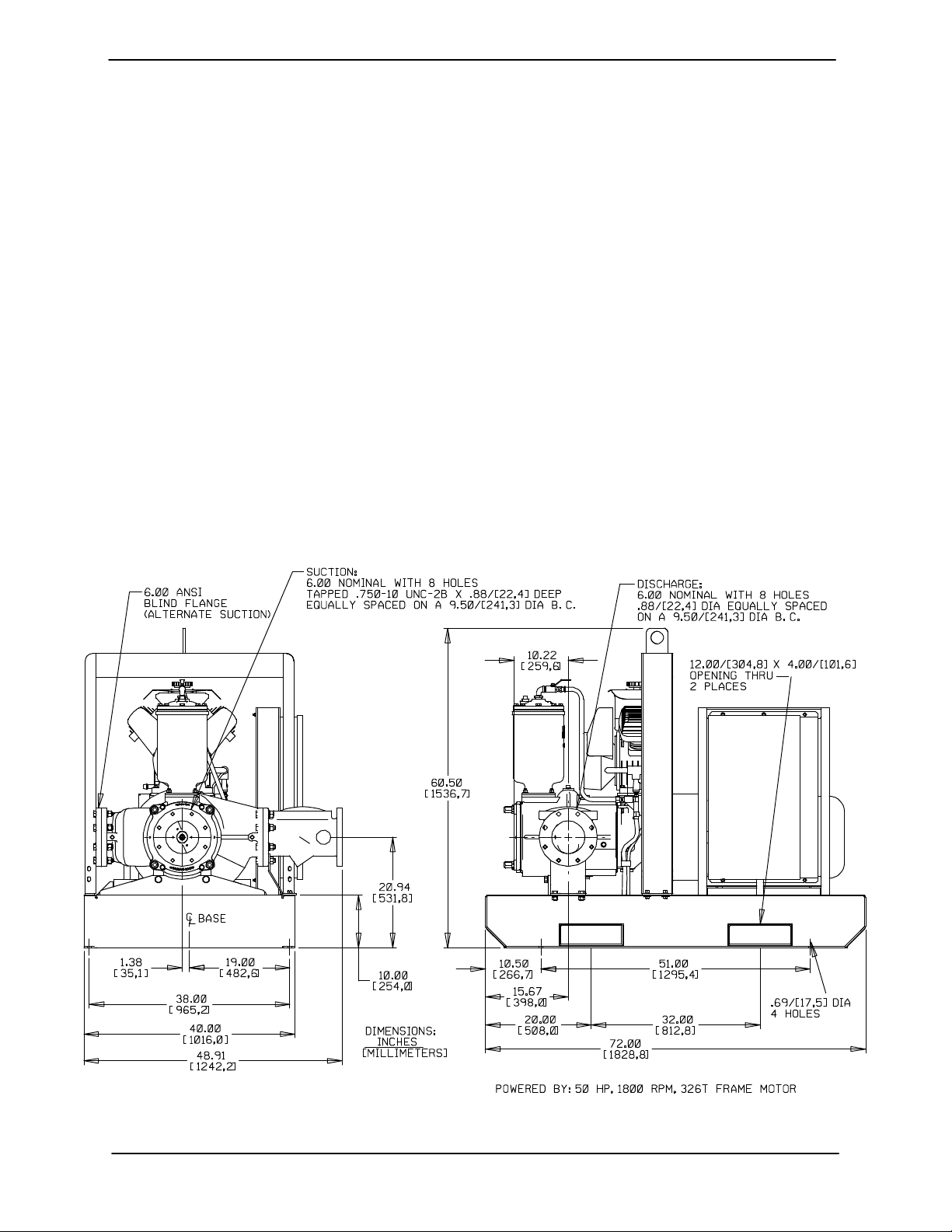
Pump Dimensions
See Figure 1 for the approximate physical dimen
sions of this pump.
Figure 1. Pump Model PA6C60C-B-E50 460/575/3
PAGE B - 1INSTALLATION
Page 10
OM-06531 PA SERIES
PREINSTALLATION INSPECTION
The pump assembly was inspected and tested be
fore shipment from the factory. Before installation,
inspect the pump for damage which may have oc
curred during shipment. Check as follows:
a. Inspect the pump for cracks, dents, damaged
threads, and other obvious damage.
b. Check for and tighten loose attaching hard
ware. Since gaskets tend to shrink after dry
ing, check for loose hardware at mating sur
faces.
c. Compare the amperes, phase, voltage and
hertz indicated on the pump motor nameplate
to the ratings indicated for the control box.
d. Carefully read all tags, decals, and markings
on the pump assembly, and perform all duties
indicated. Note that the pump shaft rotates in
the required direction.
POSITIONING PUMP
Use lifting and moving equipment in
good repair and with adequate capacity
to prevent injuries to personnel or dam
age to equipment. Attach lifting equip
ment to the lifting device fitted to the
pump. If chains or cable are wrapped
around the pump to lift it, make certain
that they are positioned so as not to
damage the pump, and so that the load
will be balanced. The bail is intended for
use in lifting the pump assembly only.
Suction and discharge hoses and pip
ing must be removed from the pump be
fore lifting.
Lifting
Only operate this pump in the direction in
dicated by the arrow on the pump body
and on the accompanying decal. Other
wise, the impeller could become loosened
from the shaft and seriously damage the
pump.
e. Check levels and lubricate as necessary. Re
fer to LUBRICATION in the Maintenance and
Repair Manual and perform duties as in
structed.
f. If the pump has been stored for more than 12
months, some of the components or lubri
cants may have exceeded their maximum
shelf life. These must be inspected or re
placed to ensure maximum pump service.
If the maximum shelf life has been exceeded, or if
anything appears to be abnormal, contact your
Gorman‐Rupp distributor or the factory to deter
mine the repair or updating policy. Do not put the
pump into service until appropriate action has
been taken.
Pump unit weights will vary depending on the
mounting and drive provided. Check the shipping
tag on the unit packaging for the actual weight, and
use lifting equipment with appropriate capacity.
Drain the pump and remove all customer‐installed
equipment such as suction and discharge hoses
or piping before attempting to lift existing, installed
units.
The pump assembly can be seriously
damaged if the chains or cables used to lift
and move the unit are improperly wrapped
around the pump.
Mounting
Locate the pump in an accessible place as close as
practical to the liquid being pumped. Level mount
ing is essential for proper operation.
The pump may have to be supported or shimmed
to provide for level operation or to eliminate vibra
tion.
PAGE B - 2 INSTALLATION
Page 11

PA SERIES OM-06531
to secure them when filled with liquid and under
pressure.
If the pump has been mounted on a
movable base, do not attempt to operate
the pump unless the unit is level. Be
sure the leveling stands are positioned
on a solid surface, and the wheels are
chocked.
SUCTION AND DISCHARGE PIPING
Pump performance is adversely effected by in
creased suction lift, discharge elevation, and fric
tion losses. See the performance curve and oper
ating range shown on Page E‐1 to be sure your
overall application allows pump to operate within
the safe operation range.
Materials
Either pipe or hose maybe used for suction and
discharge lines; however, the materials must be
compatible with the liquid being pumped. If hose is
used in suction lines, it must be the rigid‐wall, rein
forced type to prevent collapse under suction. Us
ing piping couplings in suction lines is not recom
mended.
Line Configuration
Keep suction and discharge lines as straight as
possible to minimize friction losses. Make mini
mum use of elbows and fittings, which substan
tially increase friction loss. If elbows are necessary,
use the long‐radius type to minimize friction loss.
Connections to Pump
Gauges
The pump is drilled and tapped for installing dis
charge pressure and vacuum suction gauges. It is
recommended that gauges be installed to monitor
pump performance. Seal the gauge threads with
pipe dope to ensure an airtight seal. Follow the
sealant manufacturer's recommendations when
selecting and applying the pipe dope. The pipe
dope should be compatible with the liquid being
pumped.
SUCTION LINES
To avoid air pockets which could affect pump prim
ing, the suction line must be as short and direct as
possible. When operation involves a suction lift, the
line must always slope upward to the pump from
the source of the liquid being pumped; if the line
slopes down to the pump at any point along the
suction run, air pockets will be created.
Fittings
Suction lines should be the same size as the pump
inlet. If reducers are used in suction lines, they
should be the eccentric type, and should be in
stalled with the flat part of the reducers uppermost
to avoid creating air pockets. Valves are not nor
mally used in suction lines, but if a valve is used,
install it with the stem horizontal to avoid air pock
ets.
Strainers
Be certain to use the strainer furnished with the
pump; any spherical solids which pass through the
strainer will also pass through the pump itself.
Before tightening a connecting flange, align it ex
actly with the pump port. Never pull a pipe line into
place by tightening the flange bolts and/or cou
plings.
Lines near the pump must be independently sup
ported to avoid strain on the pump which could
cause excessive vibration, decreased bearing life,
and increased shaft and seal wear. If hose‐type
lines are used, they should have adequate support
If a strainer not furnished with the pump is installed
by the pump user, make certain that the total area
of the openings in the strainer is at least three or
four times the cross section of the suction line, and
that the openings will not permit passage of solids
larger than the solids handling capability of the
pump.
This pump is designed to handle up to 3 inch (76,2
mm) diameter spherical solids.
PAGE B - 3INSTALLATION
Page 12

OM-06531 PA SERIES
Sealing
Since even a slight leak will affect priming, head,
and capacity, especially when operating with a
high suction lift, all connections in the suction line
should be sealed with pipe dope to ensure an air
tight seal. Follow the sealant manufacturer's rec
ommendations when selecting and applying the
pipe dope. The pipe dope should be compatible
with the liquid being pumped.
Suction Lines In Sumps
If a single suction line is installed in a sump, it
should be positioned away from the wall of the
sump at a distance equal to 1 1/2 times the diame
ter of the suction line.
If there is a liquid flow from an open pipe into the
sump, the flow should be kept away from the suc
tion inlet because the inflow will carry air down into
the sump, and air entering the suction line will re
duce pump efficiency.
If it is necessary to position inflow close to the suc
tion inlet, install a baffle between the inflow and the
suction inlet at a distance 1‐1/2 times the diameter
of the suction pipe. The baffle will allow entrained
air to escape from the liquid before it is drawn into
the suction inlet.
If two suction lines are installed in a single sump,
the flow paths may interact, reducing the efficiency
of one or both pumps. To avoid this, position the
suction inlets so that they are separated by a dis
tance equal to at least 3 times the diameter of the
suction pipe.
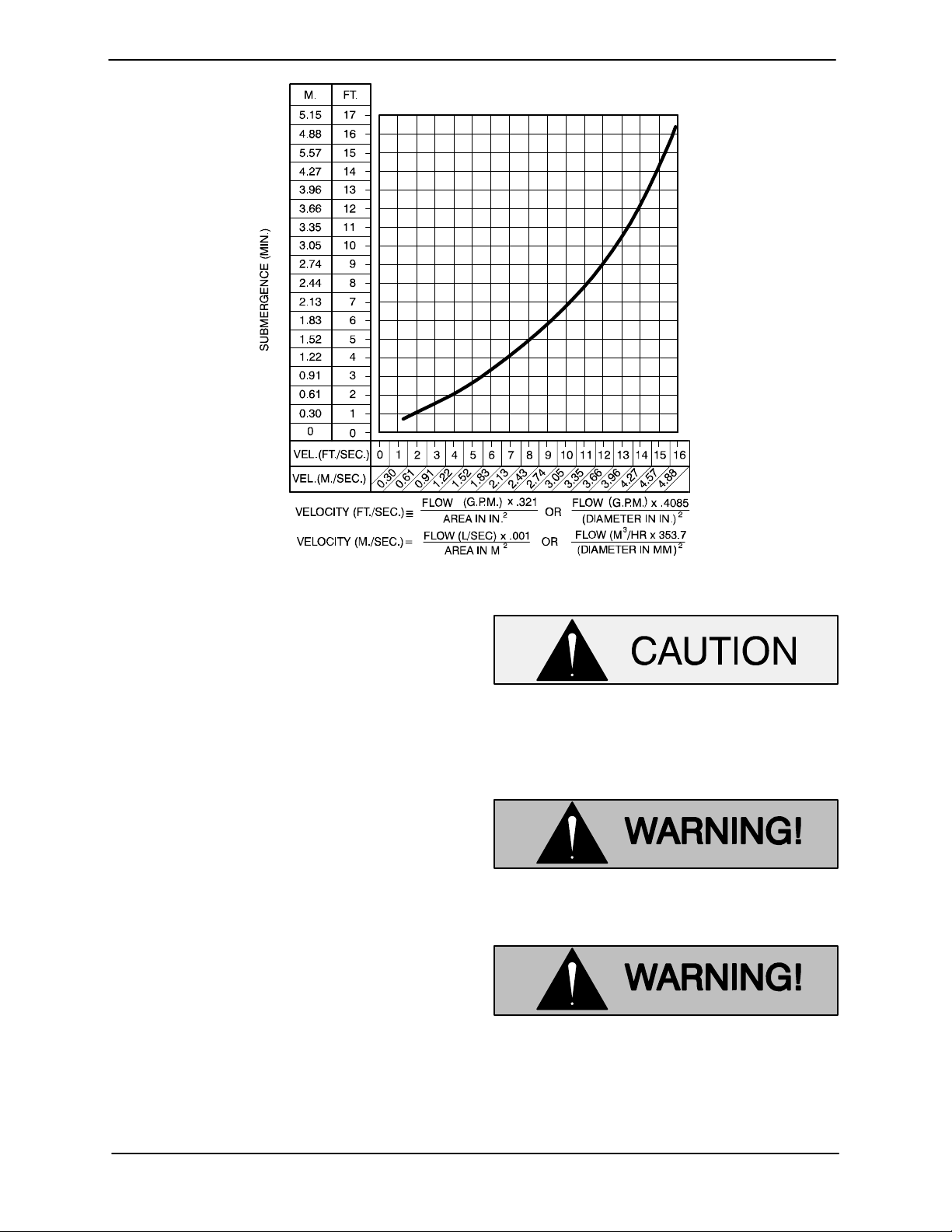
Suction Line Positioning
The depth of submergence of the suction line is
critical to efficient pump operation. Figure 2
shows recommended minimum submergence vs.
velocity.
Although not recommended, the vacuum assisted
priming feature allows the pump to be operated
temporarily in a “slurping” application with varying
water levels.
NOTE
The pipe submergence required may be reduced
by installing a standard pipe increaser fitting at the
end of the suction line. The larger opening size will
reduce the inlet velocity. Calculate the required
submergence using the following formula based
on the increased opening size (area or diameter).
PAGE B - 4 INSTALLATION
Page 13
PA SERIES OM-06531
Figure 2. Recommended Minimum Suction Line Submergence vs. Velocity
DISCHARGE LINES
Siphoning
Do not terminate the discharge line at a level lower
than that of the liquid being pumped unless a si
phon breaker is used in the line. Otherwise, a si
phoning action causing damage to the pump
could result.
Valves
This pump is designed with a check valve in the
discharge line.
If a throttling valve is desired in the discharge line,
use a valve as large as the largest pipe to minimize
friction losses. Never install a throttling valve in a
suction line.
With high discharge heads, it is recommended that
a throttling valve be installed in the discharge line
to protect the pump from excessive shock pres
sure and reverse rotation when it is stopped.
If the application involves a high discharge
head, gradually close the discharge
throttling valve before stopping the pump.
ELECTRICAL CONNECTIONS
Obtain the services of a qualified elec
trician to make all electrical connec
tions and to service the control box.
The electrical power used in this control
box is high enough to cause injury or
death. Make certain that the control box
is properly grounded after installation.
Make certain that the power source
phase and voltage matches the data on
PAGE B - 5INSTALLATION
Page 14
OM-06531 PA SERIES
the control box. Complete all electrical
connections before connecting the
power supply to the control box. Make
certain to ground the appropriate lead
of the power source before connecting
power to the control. Make certain that
the control box is properly grounded af
ter installation.
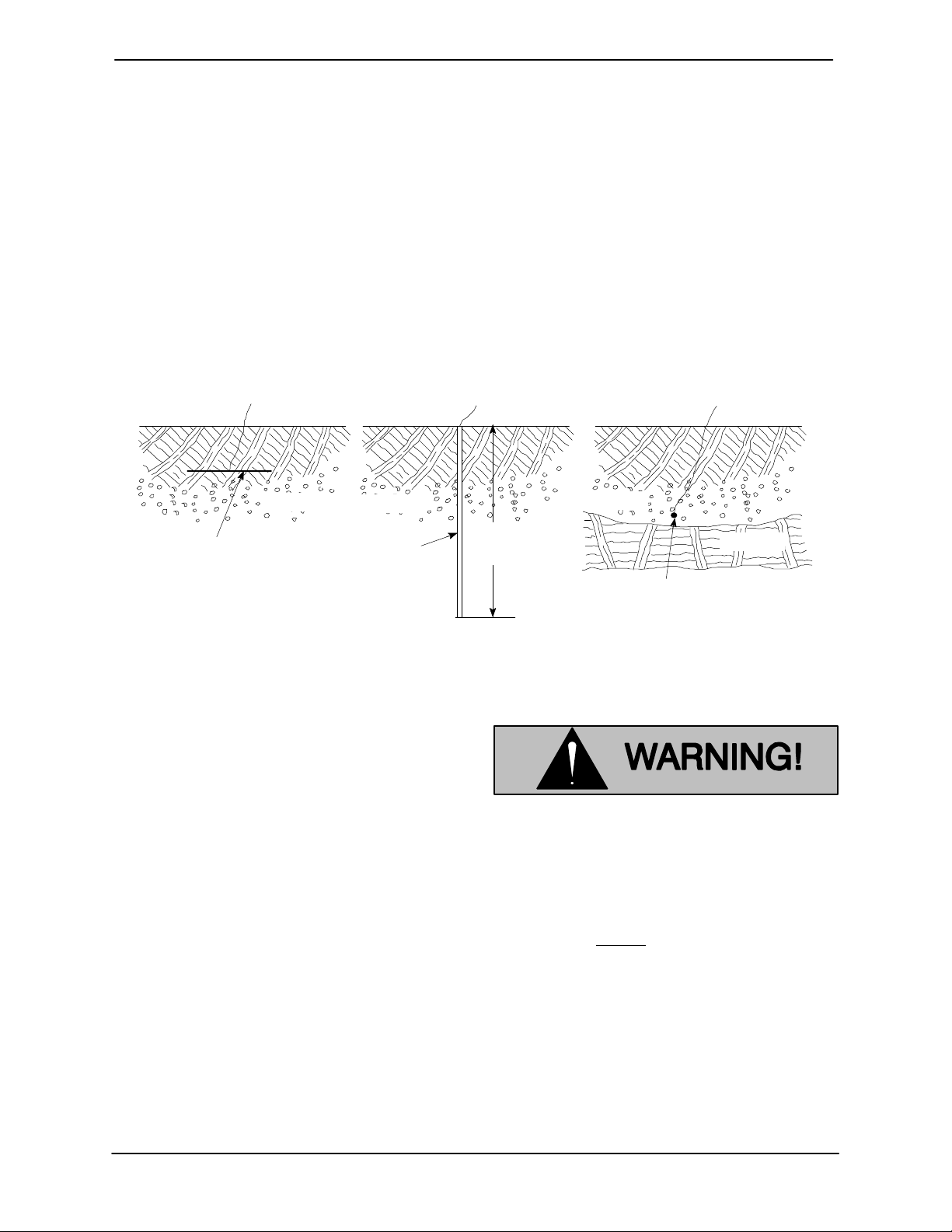
Grounding Methods
Electrically ground the installation before connect
ing the field wiring to the control box. Install a
a) PLATE ELECTRODE b) DRIVEN ELECTRODE c) BURIED ELECTRODE
SOIL
1/4 INCH STEEL
PLATE 2 SQ. FEET
(1858,1 SQ. CM)
SURFACE AREA
(MINIMUM)
SOIL
3/4 INCH (19,1
MM) NOMINAL
DIAMETER
(MINIMUM)
grounding terminal to the enclosure and connect it
to a properly embedded electrode.
The material used for the electrode must be an ex
cellent conductor of electricity, such as copper. If
iron or steel is used, it must be galvanized or other
wise metal plated to resist corrosion. Do not coat
the electrode with any material of poor conductiv
ity, such as paint or plastic.
The electrode must conform to the recommenda
tions of N.E.C. ARTICLE 250. Follow all installation
requirements of the N.E.C., and all applicable
codes. See Figure 3 for some suggested ground
ing methods.
SOIL
8 FEET
(2,4 M)
3/4 INCH (19,1 MM)
NOMINAL DIAMETER
(MINIMUM) 8 FEET
(2,4 M) LONG
ROCK
Figure 3. Suggested Grounding Methods
a. Plate Electrode: An iron or steel plate, 1/4
inch (6,4 mm) thick, completely impeded in
the ground. The plate must present a surface
area of at least 2 square feet (1858,1 sq. cm).
b. Driven Electrode: A rod or pipe, 3/4 inch
(19,1 mm) in diameter minimum, 8 feet (2,4 m)
long, completely driven into the ground.
c. Buried electrode: If rock or stone prevents
embedding the full 8 foot (2,4 m) length of the
ground rod, bury it horizontally in a trench.
Space the ground rod or plates at least 6 feet
(1,8 m) from any other electrode or ground
rod, such as those used for signal circuits, ra
dio grounds, lightning rods, etc.
The earth surrounding the ground rod or plate
must contain enough moisture to make a
good electrical connection. In dry or sandy ar
eas, pour water around the rod, or consult
qualified personnel to devise a method of im
proving the connection.
Field Wiring Connections (Incoming Power)
The electrical power used to operate
this pump is high enough to cause inju
ry or death. Obtain the services of a qu
alified electrician to make all electrical
connections. Make certain that the
pump and enclosure are properly
grounded; never use gas pipe as an
electrical ground. Be sure that the in
coming power matches the voltage and
phase of the pump and control before
connecting the power source. Do not
run the pump if the voltage is not within
the limits.
The control is designed to regulate the power sup
ply. The field wiring must be properly sized to en
sure an adequate voltage supply. The voltage
PAGE B - 6 INSTALLATION
Page 15
PA SERIES OM-06531
available at the pump motor must be within the in
dicated range.
Table 1. Pump Motor Voltage Limits
Nominal
Voltage
460 3 414 506
575 3 517 632
If the voltage is not within the recommended limits,
obtain the services of a qualified electrician to de
termine the correct field wiring size and other de
tails to ensure an adequate voltage supply.
Make certain all connections are tight and that ca
ble entry points are rainproof. Support the cable
weight, if required, to prevent excessive strain on
cable clamps and cable.
Phase
Minimum
Voltage
Maximum
Voltage
NOTE
After the power cables have been connected to the
control box, make certain the connection is water
proof.
Voltage Imbalance
Each phase of the incoming three‐phase power
must be balanced with the other two as accurately
as a commercial voltmeter will read. If the phases
are out of balance, contact your power company
and request that they correct the condition.
When necessary to change or connect power
cables to the control box, make certain the incom
ing power is OFF and LOCKED OUT. Make certain
the control box is properly grounded and that the
electrical data on the control matches the pump
motor name plate data.
Connect the power cable to the control box as
shown in the wiring diagrams in this section or in
side the control box door. Use conduit or cable
clamps to secure the power and accessory cables
to the control box. Make certain that all connec
tions are tight and that cable entry points are
rainproof.
Control Box Adjustments
For control adjustments and settings, refer to the
information inside the control box door.
To maintain overcurrent, short circuit
and ground fault protection, the man
ufacturer's instructions for selection of
the heater pack and setting of the in
stantaneous trip circuit breaker (current
interrupter) or control interface module
must be followed. Failure to follow these
instructions can result in damage to the
pump and/or serious injury to person
nel.
ALIGNMENT
Power Cable Connections
The electrical power used to operate the
control box is high enough to cause in
jury or death. Obtain the services of a
qualified electrician to make all electri
cal connections. Make certain that in
coming power to the control box is in the
off position and locked out, or that the
power supply to the control box has
been otherwise cut off and locked out,
before connecting power or accessory
cables.
The alignment of the pump and motor is critical for
trouble‐free mechanical operation. In a flexible
coupling system, the driver and pump must be
mounted so that their shafts are aligned with and
parallel to each other. It is imperative that alignment
be checked after the pump and piping are in
stalled, and before operation.
NOTE
Check Rotation, Section C, before final alignment
of the pump.
When mounted at the Gorman‐Rupp factory, driver
and pump are aligned before shipment. Misalign
ment will occur in transit and handling. Pumps
must be checked and realigned before operation.
PAGE B - 7INSTALLATION
Page 16
OM-06531 PA SERIES
Before checking alignment, tighten the foundation
bolts. The pump casing feet and/or pedestal feet,
and the driver mounting bolts should also be tightly
secured.
When checking alignment, disconnect
the power source to ensure that the
pump will remain inoperative.
Adjusting the alignment in one direction
may alter the alignment in another direc
tion. Check each procedure after altering
alignment.
AUTO‐START
The pump may be equipped with an optional auto‐
start control system which allows the pump to start
and stop as the liquid level in the wet well or sump
rises and falls.
Refer to the information which follows for installa
tion details for the optional liquid level sensing sys
tem.
equipped with a socket type connector that plugs
into a matching receptacle on the auto‐start control
box.
Standard floats are equipped with 50 feet (15,2 m)
of cable.
When installing the floats, note the following:
a. Be sure to provide sufficient room in the wet
well or sump so that floats do not get ob
structed or drawn into the suction line. If a flex
ible suction hose is used, it may be extended
to lay along the bottom of the wet well or sump
and the float can be attached to the hose
above the point where it bends along the bot
tom. Direct the suction line toward the flow,
and the float(s) away from the flow. If a stand
pipe is available, attach the float switch cable
to the standpipe in the sump at the approxi
mate desired liquid level.
b. In a single float system, the cable can be teth
ered to the suction line or standpipe approxi
mately 6 inches (152 mm) above the float.
This setting allows approximately 9 inches
(229 mm) of liquid rise between pump start/
stop. The start/stop interval may be increased
by extending the float end of the cable. The
liquid level in the sump will increase approxi
mately 8 inches (203 mm) between start/stop
intervals for every 6 inches (152 mm) of cable
increase.
Float Switch Installation
The Float Switch autostart system employs either a
single or double float switch, where a bulb raises or
lowers (floats) with the liquid level, thus activating
an enclosed miniature switch. The floats are
PAGE B - 8 INSTALLATION
c. If a double float switch system is used, posi
tion the “Start” float at the desired high water
level in the sump, and the “Stop” float at the
desired low water level in the pump.
d. Refer to Figure 4 for additional float switch
data.
Page 17

PA SERIES OM-06531
PUMP
CONTROL
BOX
ON
(Emptying)
OFF
(Filling)
OPERATING
CABLE
TETHER
RANGE
(See Table Below)
POINT
OFF
(Emptying)
1.25” Pipe
(Not Furnished)
ON
(Filling)
Figure 4. Float Switch Data
Submersible Transducer Installation
The Electronic Pressure Switch (EPS) autostart
system employs a submersible transducer level
sensor with 75 feet (22,9 m) of signal cable con
nected to the EPS.
The transducer sensor converts pressure to an
electrical signal proportional to liquid level. This
electrical signal is distributed to the digital display
on the EPS through a scaling circuit which con
verts the electrical signal to “feet of water”.
3.0
(0.9)
2.5
(.76)
2.0
(0.6)
1.5
(.46)
1.0
(0.3)
0.5
(.15)
1.0
(0.3)
APPROXIMATE FREE CORD LENGTH IN FT. (M)
2.0
(0.6)
3.0
(0.9)
c. Allow slack in the signal cable so that the sen
sor weight does not pull on the connection.
d. The wet well or sump must be vented to atmo
sphere.
e. The EPS is scaled in feet of water column. If
the measured medium is other than 1.0 spe
cific gravity, the reading on the EPS should be
divided by the specific gravity of the mea
sured medium to obtain the actual level.
4.0
(1.2)
When installing the transducer sensor, note the fol
lowing:
a. Handle the signal cable and transducer sen
sor with care during installation. Carefully
lower the sensor into the wet well or sump; do
not drop it to the bottom. To avoid clogging,
suspend the sensor off the bottom.
b. Be sure to provide sufficient room in the wet
well or sump so that the sensor does not get
drawn into the suction line. To prevent this, a
flexible suction hose may be extended to lay
along the bottom of the wet well or sump. The
sensor can then be attached to the hose
above the point where it bends along the bot
tom. See Figure 5 for a typical installation.
f. Thoroughly clean the sensor after each use
to prevent clogging.
Do not disassemble the transducer sensor
or loosen the compression nut at the signal
cable entry. This will void warranty. There
are no user‐serviceable parts inside. Do
not nick or cut the jacket of the signal
cable; this will cause leakage and void
warranty. Connect the signal cable only to
the EPS terminals for this purpose and to
no other power source.
PAGE B - 9INSTALLATION
Page 18

OM-06531 PA SERIES
SUCTION
DISCHARGE
LINE
LINE
SIGNAL CABLE
(ATTACH TO
SUCTION LINE)
SUBMERSIBLE
TRANSDUCER
(DOWNSTREAM
FROM SUCTION)
Figure 5. Typical Submersible Transducer AutoStart Pump Installation
SUCTION
STRAINER
FLOW
PAGE B - 10 INSTALLATION
Page 19

PA SERIES OM-06531
Transducer Connections
The submersible transducer sensor cable is facto
ry‐equipped with a female connector which mates
with a male connector on the back of the EPS con
trol. If removal or replacement of the female con
TRANSDUCER
SHD -V +VSIG
+ BATT
- BATT
SHIELD
-
MOTOR
RUN
+
+ TEMP
RELAY
A
RELAY
B
CAUTION-
nector is required, reconnect the cable to the con
nector as shown in Figure 6.
Once the connections are made, simply plug the
female connector into the male connector on the
back of the EPS, and refer to Section C for opera
tional procedures.
MALE
TRANSDUCER
CONNECTOR
SHIELD
BLACK
FEMALE
TRANSDUCER
CONNECTOR
RED
WHITE
TRANSDUCER
SENSOR
CABLE
HORN
RELAY
THIS COVER PLATE MUST
BE INSTALLED FOR PROPER
CONTROL OPERATION
Figure 6. Back Side of Transducer Showing Sensor Cable Connections
PAGE B - 11INSTALLATION
Page 20

PA SERIES
OM-06531
OPERATION - SECTION C
Review all SAFETY information in Section A.
Follow the instructions on all tags, labels and
decals attached to the pump.
The electrical power used to operate
this control box is high enough to cause
injury or death. Make certain that the
control handle on the control box is in
the OFF position and locked out, or that
the power supply to the control box has
been otherwise cut off and locked out,
before attempting to open or service the
control box. Tag electrical circuits to
prevent accidental start‐up.
Obtain the services of a qualified elec
trician to make all electrical connec
tions, and to troubleshoot, test and/or
service the electrical components of the
control box.
This pump is designed to handle most
non‐volatile, non‐flammable liquids
containing specified entrained solids
and corrosives. Do not attempt to pump
volatile, corrosive, or flammable liquids
which may damage the pump or endan
ger personnel as a result of pump fail
ure.
Pump operating condition points must be
within the continuous performance range
shown on the Performance Curve in Sec
tion E.
STARTING AND OPERATION
Control Box Function
The control box provides overload pro
tection and power control. Do not con
nect the pump motor directly to the in
coming power lines.
The control box is provided to facilitate operation of
the pump. It contains controls for starting and stop
ping the pump, and provides overload protection
for the pump motor. The pump control also con
tains low voltage circuits for the optional automatic
liquid level sensing device.
Component Function
The control box contains the following hand‐oper
ated switches and controls:
The control handle operates the control
box circuit breakers. In the OFF position, the
control handle opens the circuit breakers to
interrupt incoming power through the con
trol box and prevent pump operation. In the
ON position, it closes the circuit breakers to
permit pump operation. The circuit breakers
will open or “trip” automatically in the event
of a short circuit overload current. When
tripped, move the control handle to OFF and
back to ON to reset the circuit breakers.
The selector switch controls the mode of
operation. In the OFF position, it prevents all
operation of the pump. In the HAND posi
tion, it allows the pump to run continuously.
When used in conjunction with the optional
liquid level controls, the AUTO position al
lows the pump to be controlled automatical
ly by the liquid level control system.
The reset pushbutton resets the motor over
load after it has been TRIPPED by an over
load. The overload relay will trip automatical
ly if the current drawn by the motor exceeds
design specifications. Allow 10 seconds for
OPERATION PAGE C - 1
Page 21

OM-06531 PA SERIES
the relay to cool after tripping before press
ing the reset.
If replacing the heater pack, press the reset
button to set the relay.
NOTE
If the circuit breaker trips, do not reset it immedi
ately. Wait at least ten minutes before resetting the
control handle back to the ON position. If the over
load unit continues to trip, operational problems ex
ist.
The pump motor will restart as soon as
the RESET pushbutton is pressed, un
less the selector switch is in the OFF po
sition. Turn the selector switch to OFF
and move the control handle to OFF be
fore approaching the pump.
The optional liquid level system operates in
conjunction with the 3‐position switch
(HAND‐OFF‐AUTO) on the control box. After
the float(s) have been installed as described
in INSTALLATION, Section B, pump opera
tion may be automatically controlled for fill
ing or dewatering functions.
The green run light indicates the pump is
running. The light will be energized when
the 3‐position switch is in the HAND position
or when the pump is running with the switch
in the AUTO position.
Always terminate incoming power to the control
box before investigating control box circuitry prob
lems.
the pump, but does not terminate incoming power
through the field wiring connected to the control
box.
Rotation
The correct direction of pump rotation is indicated
by an arrow on the pump body or accompanying
decals. If the pump is operated in the wrong direc
tion, the impeller could become loosened from the
shaft and seriously damage the pump.
The pump must operate in the direction in
dicated by the arrow on the pump, or ac
companying decals. Reverse rotation
could damage the pump and adversely af
fect performance.
Disconnect the pump from the motor before
checking motor rotation. To check rotation, oper
ate the motor independently while observing the
direction of the motor shaft, or cooling fan.
If rotation is incorrect, have a qualified electrician
interchange any two of the three phase wires at the
line connection to change direction.
Priming
The pump will begin to prime upon startup. The air
in the suction line will be discharged from the prim
ing chamber discharge line. Complete priming is
indicated by a positive discharge pressure read
ing.
If full priming is not achieved, the discharge check
valve may be malfunctioning. If this occurs, shut
down the pump and consult the separate Mainte
nance and Repair manual for further details.
Always terminate power to the control
box before performing service func
tions.
Power through the control box may be terminated
by moving the control handle to the OFF position,
thereby opening the circuit breakers. This stops
Leakage
Once the pump is fully primed, no leakage should
be visible at pump mating surfaces, or at pump
connections or fittings. Keep all line connections
and fittings tight to maintain maximum pump effi
ciency.
OPERATIONPAGE C - 2
Page 22

PA SERIES
OM-06531
Pump Vacuum Check
Read the vacuum gauge with the pump primed
and at operation speed. Shut off the pump. The
vacuum gauge reading will immediately drop pro
portionate to static suction lift, and should then sta
bilize. If the vacuum reading falls off rapidly after
stabilization, an air leak exists. Before checking for
the source of the leak, check the point of installa
tion of the vacuum gauge.
Priming Chamber Discharge Line
Check the priming chamber discharge line for liq
uid bypass. If bypass occurs, shut down the pump.
Refer to the Maintenance and Repair Manual, dis
assemble and clean the float and valve assembly
inside the priming chamber.
Liquid Temperature And Overheating
Overheating can occur if operated with the valves
in the suction or discharge lines closed. Operating
against closed valves could bring the liquid to a
boil, build pressure, and cause the pump to rup
ture or explode. If overheating occurs, stop the
pump immediately and allow it to completely cool
before servicing it. Approach any over‐heated
pump cautiously.
Never introduce air or steam pressure into the
pump casing or piping to remove a blockage. This
could result in personal injury or damage to the
equipment. If backflushing is absolutely neces
sary, liquid pressure must be limited to 50% of the
maximum permissible operating pressure shown
on the pump performance curve.
STOPPING
Manual Stopping
Turn the selector switch on the control box to the
OFF position.
After stopping the pump, lock out and tag out the
control box to ensure that the pump will remain in
operative.
Automatic Stopping
In the automatic mode, the pump will stop when
the liquid in the wet well or sump lowers and acti
vates the “Off” float switch(s). The pump will restart
automatically when the liquid rises and activates
the “On” float switch(s).
PERIODIC CHECKS
Seal And Bearing Cavity Lubrication
Both the seal and bearing cavities were fully lubri
cated at the factory. Check the lubrication levels
before startup, and regularly thereafter as indi
cated in the Maintenance and Repair Manual.
Do not remove plates, covers, gauges,
pipe plugs, or fittings from an over
When lubrication is required, use only SAE No. 30
non‐detergent oil.
heated pump. Vapor pressure within the
pump can cause parts being disen
Bearing Temperature Check
gaged to be ejected with great force. Al
low the pump to completely cool before
servicing.
Strainer Check
Check the strainer regularly, and clean it as neces
sary. The strainer should also be checked if pump
flow rate begins to drop. Monitor and record the
vacuum suction gauge readings regularly to detect
strainer blockage.
OPERATION PAGE C - 3
Bearings normally run at higher than ambient tem
peratures because of heat generated by friction.
Temperatures up to 160F (71C) are considered
normal for bearings, and they can operate safely to
at least 180F (82C).
Checking bearing temperatures by hand is inaccu
rate. Bearing temperatures can be measured ac
curately by placing a contact‐type thermometer
against the housing. Record this temperature for
future reference.
Page 23

OM-06531 PA SERIES
A sudden increase in bearing temperatures is a
warning that the bearings are at the point of failing
to operate properly. Make certain that the bearing
lubricant is of the proper viscosity and at the cor
rect level (see LUBRICATION in the Maintenance
and Repair Manual). Bearing overheating can also
be caused by shaft misalignment and/or excessive
vibration.
When pumps are first started, the bearings may
seem to run at temperatures above normal. Con
tinued operation should bring the temperatures
down to normal levels.
COLD WEATHER PRESERVATION
In below freezing conditions, drain the pump to
prevent damage from freezing. Also, clean out any
solids by flushing with a hose. Operate the pump
for approximately one minute; this will remove any
remaining liquid that could freeze the pump rotat
ing parts. If the pump will be idle for more than a
few hours, or if it has been pumping liquids con
taining a large amount of solids, drain the pump,
and flush it thoroughly with clean water. To prevent
large solids from clogging the drain port and pre
venting the pump from completely draining, insert
a rod or stiff wire in the drain port, and agitate the
liquid during the draining process. Clean out any
remaining solids by flushing with a hose.
OPERATIONPAGE C - 4
Page 24

PA SERIES
OM-06531
TROUBLESHOOTING - SECTION D
Review all SAFETY information in Section A.
The following information is divided into two cate
gories; Pump Troubleshooting and Control Box
Troubleshooting. Additionally, there is a Pump Pre
ventive Maintenance Schedule at the end of this
section. Refer to the appropriate chart for possible
causes and remedies for your specific problem.
Before attempting to open or service the
pump:
1. Familiarize yourself with this man
ual.
2. Turn the control box selector
switch to `OFF' and lock it out to en
sure that the pump will remain in
operative.
3. Allow the pump to completely cool
if overheated.
4. Check the temperature before
opening any covers, plates, or
plugs.
5. Close the suction and discharge
valves.
6. Vent the pump slowly and cau
tiously.
7. Drain the pump.
This pump may be equipped with an op
tional automatic starting system, and
therefore subject to automatic restart.
Keep hands and clothing away from the
unit to prevent injury during automatic
operation. Disconnect the positive bat
tery cable before performing any main
tenance. Failure to do so may result in
serious personal injury.
Obtain the services of a qualified elec
trician to troubleshoot, test and/or ser
vice the electrical components of the
control box.
Pump Troubleshooting
TROUBLE POSSIBLE CAUSE PROBABLE REMEDY
PUMP FAILS TO
PRIME
PUMP STOPS OR
FAILS TO DELIVER
RATED FLOW OR
PRESSURE
Discharge check valve contami
nated, damaged, or unable to seat.
Air leak in suction line. Correct leak.
Lining of suction hose collapsed. Replace suction hose.
Leaking or worn seal or pump gasket. Check pump vacuum. Replace
Suction lift or discharge head too high. Check piping installation and install
Air compressor damaged/belts broken. Check and repair/replace.
Strainer clogged. Check strainer and clean if neces
Eductor clogged. Check and clean eductor.
Air leak in suction line. Correct leak.
Lining of suction hose collapsed. Replace suction hose.
Leaking or worn seal or pump gasket. Check pump vacuum. Replace
Clean or replace check valve.
leaking or worn seal or gasket.
bypass line if needed. See INSTAL
LATION.
sary.
leaking or worn seal or gasket.
TROUBLESHOOTING PAGE D - 1
Page 25

OM-06531
Pump Troubleshooting (Cont'd)
TROUBLE POSSIBLE CAUSE PROBABLE REMEDY
PA SERIES
PUMP STOPS OR
FAILS TO DELIVER
RATED FLOW OR
PRESSURE (cont.)
PUMP REQUIRES
TOO MUCH
POWER
Strainer clogged.
Discharge check valve clogged.
Suction intake not submerged at
proper level or sump too small.
Impeller or other wearing parts worn
or damaged.
Discharge head too high.
Suction lift too high.
Pump speed too slow. Check engine output; consult en
Belt or flexible coupling broken. Check and replace as necessary.
Pump speed too high. Check engine output.
Extreme ambient temperature. Reduce pump output.
Discharge head too low.
Fuel filter clogged. Check & replace often in extreme
Check strainer and clean if neces
sary.
Check and clean check valve.
Check installation and correct
submergence as needed.
Replace worn or damaged parts.
Check that impeller is properly
centered and rotates freely.
Free impeller of debris.Impeller clogged.
Install bypass line.
Measure lift w/vacuum gauge. Re
duce lift and/or friction losses in
suction line.
gine operation manual.
Adjust discharge valve.
operating conditions.
PUMP CLOGS
FREQUENTLY
EXCESSIVE NOISE
Dilute if possible.Liquid solution too thick.
Check and replace as required.Fuel contaminated.
Pump or jack shaft bearing(s) frozen. Disassemble, check and replace
bearing(s) as required..
Discharge flow too slow.
Suction check valve or foot valve
clogged or binding.
Liquid solution too thick.
Cavitation in pump. Reduce suction lift and/or friction
Pumping entrained air.
Impeller clogged or damaged.
Open discharge valve fully to in
crease flow rate, and run engine at
maximum governed speed.
Clean valve.
Dilute if possible.
losses in suction line. Record vac
uum and pressure gauge readings
and consult local representative or
factory.
Locate and eliminate source of air
bubble.
Secure mounting hardware.Pump or drive not securely mounted.
Clean out debris; replace damaged
parts.
TROUBLESHOOTINGPAGE D - 2
Page 26

PA SERIES
Pump Troubleshooting (Cont'd)
TROUBLE POSSIBLE CAUSE PROBABLE REMEDY
OM-06531
BEARINGS RUN
TOO HOT
Bearing temperature is high, but
within limits.
Low or incorrect lubricant.
Suction and discharge lines not prop
erly supported.
Excessive tension on drive belt.
Check bearing temperature regu
larly to monitor any increase.
Check for proper type and level of
lubricant.
Check piping installation for proper
support.
Align drive properly.Drive misaligned.
Check belt tension. Adjust as
required.
Control Box Troubleshooting
TROUBLE POSSIBLE CAUSE PROBABLE REMEDY
PUMP FAILS TO
START, OVERLOAD
UNIT NOT TRIPPED
(MANUAL MODE)
Power source incompatible with control Correct power source.
box.
No voltage at line side of circuit beaker. Check power source for blown fuse,
open overload unit, broken lead, or
loose connection.
OVERLOAD UNIT
TRIPS
No voltage at line terminals on bottom Check power source for blown fuse,
of overload unit in control box. open disconnect, broken wire, or
loose connection.
Low or high voltage, or excessive volt‐ Measure voltage at control box.
age drop between pump and control Check that wiring is correct type, size,
box. and length. (See Field Wiring
Connections,Section B).
Power input phases not If imbalance exceeds 1 percent,
balanced. notify power company
Control box not compatible with pump. Electrical data on control box and
pump name plate must agree. Re‐
place control box if not in agreement.
Foreign object locking impeller or Remove foreign material or replace
bearing frozen. damaged bearing. If bearing is
damaged, check for water in motor
housing.
Motor windings short‐circuited. Check motor windings with
ohmmeter.
TROUBLESHOOTING PAGE D - 3
Page 27

OM-06531
PA SERIES
PUMP PREVENTIVE MAINTENANCE
Since pump applications are seldom identical, and
pump wear is directly affected by such things as
the abrasive qualities, pressure and temperature
of the liquid being pumped, this section is intended
only to provide general recommendations and
practices for preventive maintenance. Regardless
of the application however, following a routine pre
ventive maintenance schedule will help assure
trouble‐free performance and long life from your
Gorman‐Rupp pump. For specific questions con
cerning your application, contact your Gorman‐
Rupp distributor or the Gorman‐Rupp Company.
Record keeping is an essential component of a
good preventive maintenance program. Changes
in suction and discharge gauge readings (if so
equipped) between regularly scheduled inspec
tions can indicate problems that can be corrected
before system damage or catastrophic failure oc
curs. The appearance of wearing parts should also
be documented at each inspection for comparison
as well. Also, if records indicate that a certain part
(such as the seal) fails at approximately the same
duty cycle, the part can be checked and replaced
before failure occurs, reducing unscheduled down
time.
For new applications, a first inspection of wearing
parts at 250 hours will give insight into the wear rate
for your particular application. Subsequent inspec
tions should be performed at the intervals shown
on the chart below. Critical applications should be
inspected more frequently.
Preventive Maintenance Schedule
Service Interval*
Item
General Condition (Temperature, Unusual
Noises or Vibrations, Cracks, Leaks,
Loose Hardware, Etc.) I
Pump Performance (Gauges, Speed, Flow) I
Bearing Lubrication I R
Seal Lubrication (And Packing Adjustment,
If So Equipped) I R
V‐Belts (If So Equipped) I
Air Release Valve Plunger Rod (If So Equipped) I C
Front Impeller Clearance (Wear Plate) I
Rear Impeller Clearance (Seal Plate) I
Check Valve I
Pressure Relief Valve (If So Equipped) C
Pump and Driver Alignment I
Shaft Deflection I
Bearings I
Bearing Housing I
Piping I
Driver Lubrication - See Mfgr's Literature
Daily Weekly Monthly Semi‐
Annually
Annually
Legend:
I = Inspect, Clean, Adjust, Repair or Replace as Necessary
C = Clean
R = Replace
* Service interval based on an intermittent duty cycle equal to approximately 4000 hours annually.
Adjust schedule as required for lower or higher duty cycles or extreme operating conditions.
TROUBLESHOOTINGPAGE D - 4
Page 28

PA SERIES
OM-06531
PUMP MAINTENANCE AND REPAIR - SECTION E
MAINTENANCE AND REPAIR OF THE WEARING PARTS OF THE PUMP WILL MAINTAIN PEAK
OPERATING PERFORMANCE.
STANDARD PERFORMANCE FOR PUMP MODEL PA6C60C-B-E50 460/575/3
Based on 70F (21C) clear water at sea level
with minimum suction lift. Since pump installations
are seldom identical, your performance may be dif
ferent due to such factors as viscosity, specific
gravity, elevation, temperature, and impeller trim.
Contact the Gorman‐Rupp Company to verify per
formance or part numbers.
Pump speed and operating condition
If your pump serial number is followed by an “N”,
your pump is NOT a standard production model.
MAINTENANCE & REPAIR PAGE E - 1
points must be within the continuous per
formance range shown on the curve.
Page 29

OM-06531 PA SERIES
PARTS PAGE
ILLUSTRATION
Figure 1. Pump Model PA6C60C-B-E50 460/575/3
MAINTENANCE & REPAIRPAGE E - 2
Page 30

PA SERIES
OM-06531
Pump Model PA6C60C-B-E50 460/575/3
Parts List
(From S/N 1528569 Up)
If your pump serial number is followed by an “N”, your pump is NOT a standard production model. Contact
the Gorman‐Rupp Company to verify part numbers.
ITEM
PART NAME PART
NO.
NUMBER
MAT'L
CODE
QTY ITEM
NO.
PART NAME PART
NUMBER
MAT'L
CODE
QTY
1 PUMP END ASSEMBLY PA6C60C-B-(E50) 1
2 HEX HEAD CAP SCREW B0606 15991 8
3 LOCK WASHER J06 15991 8
4 PARAFLEX COUPLING 24340-104 --- 1
5 THREADED INSERT 21769-163 --- 8
6 COUPLING GUARD ASSY 42342-258 24150 1
7 HEX NUT D10 15991 14
8 LOCK WASHER J10 15991 14
9 50 HP, 1800 RPM MOTOR ---
-460V 28226-442 --- 1
-575V 28226-481 --- 1
10 HOIST BAIL ASSEMBLY 44713-053 24150 1
11 HEX NUT D08 15991 10
12 LOCK WASHER J08 15991 12
13 MOTOR SUPPORT ASSY 41833-043 24150 1
14 HEX NUT D04 15991 5
15 LOCK WASHER J04 15991 5
16 MT BRACKET ASSY 41888-231 24150 1
17 FLAT WASHER K04 15991 5
18 HEX HEAD CAP SCREW B0404 15991 5
19 CONTROL BOX
-460V 27515-305 --- 1
-575V 47631-183 --- 1
20 HEX HEAD CAP SCREW B1010 15991 4
21 FLAT WASHER K10 15991 10
22 HEX HEAD CAP SCREW B0805 15991 12
INDICATES PARTS RECOMMENDED FOR STOCK
23 CONT BOX/MTR CABLE 47325-015 --- 1
24 FLAT WASHER K08 15991 4
25 HEX HEAD CAP SCREW B1008 15991 4
26 FLEX SKID BASE ASSY 41565-601 24150 1
27 DISCHARGE SUPPORT 34335-168 15080 1
28 HEX HEAD CAP SCREW B1006 15991 6
29 LOCK WASHER J12 15991 2
30 HEX HEAD CAP SCREW B1206 15991 2
31 PUMP SUPPORT BRKT 34266-047 15080 1
32 CLAMP 27111-348 --- 2
33 PUMP SUPP BRKT ASSY 41888-252 24150 1
NOT SHOWN:
MOTOR VOLTAGE TAG
-460V 38816-460 --- 1
-575V 38816-128 --- 1
OIL FILL DECAL 38816-194 --- 1
G‐R DECAL GR-06 --- 2
PRIME AIRE DECAL 38812-078 --- 4
WARNING DECAL 38816-345 --- 2
INSTRUCTION TAG 38817-085 --- 1
INSTRUCTION DECAL 38816-331 --- 2
GUARD WARNING DECAL 38816-062 --- 1
460V CBL ASSY INST 47117-001 --- 1
-460V HEATER PACK 27521-210 --- 1
575V CBL ASSY INST 47117-008 --- 1
-575V HEATER PACK 27521-209 --- 1
MAINTENANCE & REPAIR PAGE E - 3
Page 31

OM-06531 PA SERIES
ILLUSTRATION
Figure 2. Pump End Assembly PA6C60C-B-(E50)
MAINTENANCE & REPAIRPAGE E - 4
Page 32

PA SERIES
ITEM
PART NAME PART
NO.
PA6C60C-B-(E50) Pump End Assembly
Parts List
NUMBER
MAT'L
CODE
QTY ITEM
NO.
PART NAME PART
NUMBER
OM-06531
MAT'L
CODE
QTY
1 PUMP END ASSEMBLY 66F60C-B-(E50) 1
2 PRIMING CHAMBER KIT 48275-005 --- 1
3 HOSE BARB FITTING 26523-047 --- 1
4 CONNECTOR S1598 --- 1
5 1/2” ID X 30” LG HOSE 18513-113 --- 1
6 AIR COMPRESSOR ASSY 46181-906 --- 1
7 BELT GUARD ASSY 42351-326 24150 1
8 HEX HEAD CAP SCREW B0610 15991 4
9 LOCK WASHER J06 15991 4
10 FLAT WASHER K06 15991 4
11 HEX HEAD CAP SCREW B0402 15991 2
12 FLAT WASHER K04 15991 2
13 LOCK WASHER J04 15991 2
14 SPACER 31141-033 15000 4
15 SYNCHRONOUS BELT 24186-008 --- 1
16 BUSHING 24131-495 --- 1
17 SPROCKET 24271-112 --- 1
18 HOSE BARB FITTING 26523-446 --- 2
19 HOSE CLAMP 26518-666 --- 1
20 1/2” ID X 20” LG HOSE 18513-113 --- 1
INDICATES PARTS RECOMMENDED FOR STOCK
21 HOSE BARB FTG 26523-387 --- 1
22 HOSE CLAMP 26518-642 --- 1
23 3/8” ID X 24 LG HOSE 18513-053 --- 1
24 CLAMP 27111-348 --- 1
25 1/2” CHECK VALVE 26641-091 --- 1
26 DISCH CHECK VALVE KIT 48274-015 --- 1
-6” CHECK VALVE 26642-126 --- 1
--FLAPPER 26688-001 --- 1
--COVER O‐RING 25152-377 --- 1
-FLANGE GASKET 25113-036 --- 1
NOT SHOWN:
STRAINER 7823A 24000 1
SUCTION STICKER 6588AG --- 1
DISCHARGE STICKER 6588BJ --- 1
WARNING DECAL 2613FE --- 1
G‐R DECAL GR-06 --- 1
LUBE DECAL 11421A --- 1
OIL LEVEL DECAL 38816-123 --- 1
ROTATION DECAL 2613M --- 1
MAINTENANCE & REPAIR PAGE E - 5
Page 33

OM-06531 PA SERIES
ILLUSTRATION
Figure 3. 66F60C-B-(E50) Pump End Assembly
MAINTENANCE & REPAIRPAGE E - 6
Page 34

PA SERIES
OM-06531
PARTS LIST
66F60C-B-(E50) Pump End Assembly
ITEM
NO.
1 PUMP CASING 38218-303 11010 1
2 REPAIR ROTATING ASSEMBLY 44163-530 --- 1
3 SIGHT GAUGE S1471 --- 1
4 GASKET 38687-053 19060 1
5 COVER PLATE 33541-045 15080 1
6 HEX HEAD CAP SCREW B0805 15991 4
7 LOCK WASHER J08 15991 12
8 PIPE PLUG P08 15079 4
8A CASING DRAIN PLUG P08 15079 1
8B SEAL CAVITY DRAIN PLUG P08 15079 1
9 VENTED PIPE PLUG 4823A 15079 1
10 BUSHING 24131-496 --- 1
11 SPROCKET 24271-112 --- 1
12 HEX HEAD CAP SCREW B0806 15991 4
13 O‐RING S1676 --- 2
14 O‐RING 25152-381 --- 1
15 SHIM 13131-3 17040 8
16 PIPE PLUG P12 15079 1
17 STREET ELBOW 25412-004 --- 1
18 STUD C1213 15991 4
19 O‐RING 25152-453 --- 1
20 WEAR PLATE 38691-864 11010 1
21 LOCK WASHER J06 17090 4
22 HEX HEAD CAP SCREW B0604-1/2 17000 4
23 LOCK COLLAR 38115-551 15001 4
24 ADJUSTING SCREW 31871-070 1500G 4
25 BACK COVER NUT 31871-073 15000 4
26 HEX HEAD CAP SCREW B0804-1/2 15991 4
27 BACK COVER PLATE 38243-468 11010 1
28 LOCK WASHER J12 15991 8
29 HEX NUT D12 15991 8
30 HEX HEAD CAP SCREW B1213 15991 8
31 BLIND FLANGE ASSEMBLY 42111-349 --- 1
32 GASKET 25113-036 --- 1
33 SHIPPING PLUG 11495B 15079 1
34 SYNCHRONOUS BELT 24186-008 --- REF
NOT SHOWN:
PART NAME
NAME PLATE 38818-127 13000 1
DRIVE SCREW BM#04-03 17000 4
SUCTION STICKER 6588AG --- 1
DISCHARGE STICKER 6588BJ --- 1
WARNING DECAL 2613FE --- 1
G‐R DECAL GR-06 --- 1
ROTATION DECAL 2613M --- 1
LUBE DECAL 11421A --- 1
OIL LEVEL DECAL 38816-123 --- 1
PART
NUMBER
MAT'L
CODE
QTY
INDICATES PARTS RECOMMENDED FOR STOCK
MAINTENANCE & REPAIR PAGE E - 7
Page 35

OM-06531 PA SERIES
ILLUSTRATION
Figure 4. 44163-530 Repair Rotating Assembly
MAINTENANCE & REPAIRPAGE E - 8
Page 36

PA SERIES
OM-06531
PARTS LIST
44163-530 Repair Rotating Assembly
ITEM
NO.
1 IMPELLER 38615-097 11010 1
2 SEAL ASSEMBLY 46512-149 --- 1
3 BALL BEARING 23422-019 --- 1
4 BEARING HOUSING 38251-513 10000 1
5 VENTED PIPE PLUG 4823A 15079 1
6 AIR VENT S1530 --- 1
7 REDUCER PIPE BUSHING AP0802 15079 1
8 BALL BEARING 23422-414 --- 1
9 MOUNTING FLANGE 38545-009 11010 1
10 IMPELLER SHAFT 38515-592 1706H 1
11 OIL SEAL S1907 --- 1
12 RETAINING RING S720 --- 1
13 THRUST WASHER 31134-115 15000 1
14 HEX HEAD CAP SCREW 21632-937 --- 6
15 LOCK WASHER J06 15991 6
16 GASKET 38683-474 18000 1
17 OIL SEAL 25227-771 --- 1
18 HEX HEAD CAP SCREW B0805-1/2 15991 4
19 LOCK WASHER J08 15991 4
20 SEAL PLATE 38272-256 10000 1
21 SOCKET HEAD CAP SCREW DM1004S 17090 1
22 IMPELLER WASHER 31514-015 17000 1
23 SIGHT GAUGE S1471 --- 1
24 PIPE PLUG P08 15079 1
24A BEARING CAVITY DRAIN PLUG P08 15079 1
24B SEAL CAVITY DRAIN PLUG P08 15079 1
25 INTERMEDIATE GUARD 42381-509 24152 2
26 PIPE PLUG P12 15079 1
27 O‐RING 25154-131 --- 1
28 ADJ SHIM SET 48261-057 --- 1
29 SHAFT SLEEVE 31163-019 1706H 1
30 AIR COMP DRIVE KEY 24113-603 --- 1
31 SHAFT KEY 24113-603 --- 1
32 SHIPPING PLUG 11495B 15079 2
33 ADJ SHIM 13131-3 17040 8
34 O‐RING S1676 --- 1
35 O‐RING 25152-381 --- 1
NOT SHOWN:
PART NAME
INSTRUCTION TAG 6588U --- 1
PART
NUMBER
MAT'L
CODE
QTY
INDICATES PARTS RECOMMENDED FOR STOCK
MAINTENANCE & REPAIR PAGE E - 9
Page 37

OM-06531 PA SERIES
ILLUSTRATION
Figure 5. 48275-005 Priming Chamber Kit
ITEM
NO.
1 PRIMING CHAMBER ASSY 46112-709 --- 1
2 PIPE BUSHING AP1608 11999 1
3 STREET ELBOW RS08 11999 1
4 BALL VALVE 26631-052 --- 1
5 STUD C0809 15991 4
6 HEX NUT D08 15991 4
7 LOCK WASHER J08 15991 4
8 GASKET 38687-053 19060 1
9 BAFFLE 31113-011 17000 1
INDICATES PARTS RECOMMENDED FOR STOCK
PART NAME
PART
NUMBER
MAT'L
CODE
MAINTENANCE & REPAIRPAGE E - 10
QTY
Page 38

PA SERIES
OM-06531
ILLUSTRATION
Figure 6. 46112-709 Priming Chamber Assembly
PARTS LIST
ITEM
NO.
1 PRIMING VALVE 26664-007 --- 1
2 HEX HD CAPSCREW B0806 15991 8
3 LOCKWASHER J08 15991 8
4 PRIMING VALVE GASKET 38683-657 19060 1
5 PRIMING CHAMBER 38343-020 10000 1
6 STRAINER ASSY 46641-222 17000 1
INDICATES PARTS RECOMMENDED FOR STOCK
MAINTENANCE & REPAIR PAGE E - 11
PART NAME
-ORIFICE BUTTON 26688-021 --- 1
PART
NUMBER
MAT'L
CODE
QTY
Page 39

OM-06531 PA SERIES
ILLUSTRATION
Figure 7. 46181-906 Air Compressor Assembly
ITEM
NO.
1 MACH SCREW X#10-02 15991 4
2 HEX NUT D#10 15991 4
3 LOCK WASHER J#10 15991 4
4 FLAT WASHER K#10 15991 4
5 AIR COMPRESSOR COVER 38354-043 15120 1
6 AIR COMPRESSOR 26813-111 --- 1
7 PIPE CAP V06 15079 1
8 PIPE NIPPLE T0616 15079 1
9 90° ADAPTER 3/8” 25412-003 --- 1
10 PULLEY ASSEMBLY 44112-003 --- 1
11 AIR COMPRESSOR KNOB 38429-501 19220 1
12 SERVICE TEE US08 11999 1
13 REDUCER PIPE BUSHING AP0806 15079 1
14 VENTURI 26817-002 --- 1
15 PIPE CPLG AE08 15079 1
16 PIPE ELBOW R08 11999 1
17 PRESSURE RELIEF VALVE 26662-028 --- 1
PART NAME
PART
NUMBER
MAT'L
CODE
MAINTENANCE & REPAIRPAGE E - 12
QTY
Page 40

PA SERIES
OM-06531
PUMP AND SEAL DISASSEMBLY AND REASSEMBLY
Review all SAFETY information in Section A.
Follow the instructions on all tags, label and de
cals attached to the pump.
This pump requires little service due to its rugged,
minimum‐maintenance design. However, if it be
comes necessary to inspect or replace the wearing
parts, follow these instructions which are keyed to
the illustrations (see Figures 1 through 7) and the
corresponding Parts Lists. Maintenance and repair
instructions for the air compressor are covered
separately in specific literature available from the
manufacturer.
Some pump service functions may be performed
without separating the pump end assembly from
the power source. However, the priming chamber
(2, Figure 2) and discharge check valve assembly
(26, Figure 2) must be removed to service most
pump components. The following instructions as
sume complete disassembly of the pump is re
quired.
Before attempting to service the pump, lock out
and tag out incoming power to the control box and
take precautions to ensure that it will remain inop
erative. Close all valves in the suction and dis
charge lines and drain the pump casing by remov
ing the casing drain plug (8A, Figure 3). Clean and
reinstall the drain plug.
This manual will alert personnel to
known procedures which require spe
cial attention, to those which could
damage equipment, and to those which
could be dangerous to personnel. How
ever, this manual cannot possibly antici
pate and provide detailed instructions
and precautions for every situation that
might occur during maintenance of the
unit. Therefore, it is the responsibility of
the owner/maintenance personnel to
ensure that only safe, established main
tenance procedures are used, and that
any procedures not addressed in this
manual are performed only after estab
lishing that neither personal safety nor
pump integrity are compromised by
such practices.
Before attempting to open or service the
pump:
1. Familiarize yourself with this man
ual.
2. Turn the control box selector
switch to `OFF' and lock it out to en
sure that the pump will remain in
operative.
3. Allow the pump to completely cool
if overheated.
4. Check the temperature and make
sure it is cool before opening any
covers, plates, gauges, or plugs.
5. Close the suction and discharge
valves.
6. Vent the pump slowly and cau
tiously.
7. Drain the pump.
This pump may be equipped with an op
tional automatic starting system, and
therefore subject to automatic restart.
Keep hands and clothing away from the
unit to prevent injury during automatic
operation. Lock out the power from the
control box to ensure that the pump will
remain inoperative. Failure to do so
may result in serious personal injury.
Obtain the services of a qualified elec
trician to troubleshoot, test and/or ser
vice the electrical components of the
control box.
MAINTENANCE & REPAIR PAGE E - 13
Page 41

Discharge Check Valve Removal and
Disassembly
(Figure 2)
PA SERIESOM-06531
Use only replacement parts provided or
approved by Gorman‐Rupp. Use of non‐
authorized parts may result in damage to
the equipment and/or injury to personnel
and will invalidate the warranty.
Priming Chamber Removal And Disassembly
(Figure 5)
Disconnect the air discharge tubing from the prim
ing chamber assembly (2, Figure 2). Support the
priming chamber assembly using a sling and a
suitable lifting device. Remove the hardware (6
and 7) and separate the priming chamber assem
bly (1), gasket (8) and baffle (9) from the pump cas
ing.
(Figure 6)
Remove the hardware (2 and 3) securing the prim
ing valve (1) to the priming chamber (5). Carefully
lift the valve components from the priming cham
ber. Remove the gasket (4) and clean the mating
surfaces.
If the priming valve float is stuck or the strainer (6) is
clogged, it can usually be cleaned without further
disassembly.
Support the discharge check valve assembly (26)
using a sling and a suitable lifting device. Remove
the hardware (not shown) securing the check valve
to the pump and separate the discharge check
valve assembly and gasket (not shown) from the
pump assembly (1).
The flapper and cover O‐ring are the only service
able parts of the check valve. If the flapper requires
replacement, remove the hardware securing the
cover. Separate the cover and O‐ring and remove
the flapper.
Back Cover Plate and Wear Plate Removal
(Figure 3)
The wear plate (20) is easily accessible and may be
serviced by removing the back cover plate assem
bly (27). Before attempting to service the pump, re
move the casing drain plug (8A) and drain the
pump casing. Clean and reinstall the drain plug.
Remove the back cover nuts (25) and pry the back
cover and assembled wear plate from the pump
casing (1).
NOTE
An alternate method of removing the back cover
from the pump casing is to remove the back cover
nuts (25) and two diagonally opposing locking col
lars (23). Use the adjusting screws (24) to press the
back cover out of the pump casing.
The only serviceable part of the priming valve is the
orifice button (not shown). If liquid continues to by
pass through the priming chamber after adjusting
the orifice button (see Priming Chamber Reas
sembly and Installation for adjustment), the but
ton may require replacement. To replace the orifice
button, remove one of the “e‐clips” from the pivot
pin closest to the orifice button and remove the piv
ot pin. This will allow the linkage to be raised high
enough to access the orifice button.
Remove the hex nut and lock washer securing the
orifice button to the linkage bar and unscrew the
orifice button from the linkage bar.
Remove and discard the O‐rings (13 and19).
Inspect the wear plate and, if replacement is re
quired, remove the hardware (21 and 22) securing
it to the back cover plate.
Draining Oil From Seal Cavity
(Figure 3)
If any further disassembly is to be performed on the
pump, the seal oil cavity must be drained to pre
vent the oil in the seal cavity from escaping as the
pump casing is removed.
Position a, clean container (2 gallon [7,8 liter] mini
mum) under the seal cavity drain plugs (8B, Figure
MAINTENANCE & REPAIRPAGE E - 14
Page 42

PA SERIES
OM-06531
3 and 24B, Figure 4). Remove the plugs and drain
the oil from the seal cavity into the container. For
shorter drain time, remove the vented plug (5, Fig
ure 4). Clean and reinstall the drain plugs and vent
plug. Inspect the oil for water, dirt or a cloudy condi
tion which could indicate seal failure.
Separating Pump End From Power Source
(Figure 1)
Further disassembly of the pump requires separat
ing the pump end from the power source. Discon
nect the discharge piping from the pump casing.
Disengage the hardware (2 and 3) and remove the
coupling guard (6).
See Figure 2 and disengage the hardware 11, 12
and 13 and remove the belt guard (7). Remove the
hardware (8, 9 and 10) securing the air compres
sor assembly (6) to the mounting flange (9, Figure
4). Use a pry bar to raise the air compressor high
enough to remove the spacers (14). Remove the
belt (15) from the air compressor drive pulley (not
shown).
Disconnect all hoses and fittings from the air com
pressor and use a suitable hoist and sling to re
move the air compressor assembly.
Remove the hardware (29 and 30) securing the
pump casing to the pump support bracket (31) and
use a sling and suitable lifting device to pull the
pump end straight away from the motor. Remove
the coupling half from the impeller shaft.
(Figure 2)
Remove the belt (15). Remove the setscrews from
the center of the bushing (16). Reinstall the
setscrews in the tapped holes in the bushing and
tighten them in an alternating pattern until the
bushing is “jacked” out of the sprocket (17). Slide
the bushing and sprocket off the shaft. Remove the
key (30, Figure 4).
Loosening Impeller
(Figure 4)
With the pump end separated from the power
source, wedge a block of wood between the vanes
of the impeller (1) and the pump casing (1, Figure
3) to prevent rotation.
Disconnect the hardware securing the halves of
the coupling (4) and separate the coupling halves.
Remove the half of the coupling and the drive key
(31, Figure 4) from the impeller shaft.
Use lifting and moving equipment in
good repair and with adequate capacity
to prevent injuries to personnel or dam
age to equipment. If slings or chains are
used to move the pump or components,
make sure that the load is balanced;
otherwise serious personal injury or
death could result. Suction and dis
charge hoses and piping must be re
moved from the pump before lifting.
Install the drive key (31) in the shaft keyway. Install
a lathe dog on the drive end of the shaft (10) with
the “V” notch positioned over the shaft key.
With the impeller rotation still blocked, see Figure 8
and use a long piece of heavy bar stock to pry
against the arm of the lathe dog in a counterclock
wise direction (when facing the drive end of the
shaft). Use caution not to damage the shaft or key
way. When the impeller breaks loose, remove the
lathe dog, key and wood block.
NOTE
Do not remove the impeller until the rotating assem
bly has been removed from the pump casing.
MAINTENANCE & REPAIR PAGE E - 15
Page 43

PA SERIESOM-06531
Turn
Counterclockwise
Lathe Dog Arm
“V” Notch
Heavy
Bar Stock
Figure 8. Loosening Impeller
Pump Casing Removal
(Figure 3)
Position the pump assembly on a flat work surface
with the rotating assembly (2) positioned up. Sup
port the pump casing (1) using wood blocks or oth
er suitable material. Make sure the pump assembly
is secure and stable before proceeding with pump
disassembly.
Shaft Key
Impeller Shaft
Lathe Dog
Setscrew
nect a sling and suitable lifting device to the “S”
hooks.
Remove the hardware (7 and 12) securing the
pump casing (1) to the rotating assembly (2). Use
the lifting device to pull the rotating assembly up
out of the pump casing and position it on the work
surface. Remove the shims (15) and clean the con
tacting surfaces. Tie and tag the shims or measure
and record their thickness for ease of reassembly.
Impeller Removal
(Figure 4)
With the rotating assembly removed from the
pump casing, unscrew the impeller (1) in a coun
terclockwise direction (when facing the impeller).
Use caution when unscrewing the impeller; ten
sion on the shaft seal spring will be released as the
impeller is removed. Inspect the impeller and re
place it if cracked or badly worn.
Remove the impeller adjusting shims (28); tie and
tag the shims, or measure and record their thick
ness for ease of reassembly.
Seal Removal
(Figures 4 and 10)
Remove the spring centering washer and seal
spring. Slide the shaft sleeve (29) and rotating por
tion of the seal (consisting of the bellows, retainer,
and rotating element) off the shaft as a unit.
Use lifting and moving equipment in
good repair and with adequate capacity
to prevent injuries to personnel or dam
age to equipment. If slings or chains are
used to move the pump or components,
make sure that the load is balanced;
otherwise serious personal injury or
death could result. Suction and dis
charge hoses and piping must be re
moved from the pump before lifting.
NOTE
Drain the oil from the seal cavity before removing
the pump casing. See Draining Oil From Seal Cav
ity.
See Figure 4 and install a pair of “S” hooks in two
opposing holes in the mounting flange (9). Con
Apply oil to the sleeve and work it up under the rub
ber bellows. Slide the rotating portion of the seal off
the sleeve.
Slide a pair of stiff wires with hooked ends along
the shaft and hook the stationary seat from the
back side. Pull the stationary seat and O‐ring from
the seal plate.
An alternate method of removing the stationary
seal components is to remove the hardware (18
and 19) and separate the seal plate from the bear
ing housing (4). Position the seal plate on a flat sur
face with the impeller side down. Use a wooden
dowel or other suitable tool to press on the back
side of the stationary seat until the seat and O‐ring
can be removed.
Remove the shaft sleeve O‐ring (27) and seal plate
O‐ring (34).
MAINTENANCE & REPAIRPAGE E - 16
Page 44

PA SERIES
OM-06531
If no further disassembly is required, refer to Seal
Installation.
Shaft and Bearing Removal and Disassembly
(Figure 4)
When the pump is properly operated and main
tained, the bearing housing should not require dis
assembly. Disassemble the shaft and bearings
only when there is evidence of wear or damage.
Shaft and bearing disassembly in the field
is not recommended. These operations
should be performed only in a properly
equipped shop by qualified personnel.
Remove the bearing housing drain plug (24A) and
drain the lubricant. Clean and reinstall the drain
plug.
Disengage the hardware (14 and 15) and remove
the mounting flange (9), gasket (16) and oil seal
(11). Use a suitably sized dowel to press the oil seal
from the mounting flange.
Place a block of wood against the impeller end of
the shaft (10) and tap the shaft and assembled
bearings (3 and 8) from the bearing housing. Press
the oil seal (17) from the bearing housing.
Remove the bearing housing O‐ring (34).
soaked in cleaning solvent. Inspect the parts for
wear or damage and replace as necessary.
Most cleaning solvents are toxic and
flammable. Use them only in a well ven
tilated area free from excessive heat,
sparks, and flame. Read and follow all
precautions printed on solvent contain
ers.
Clean the bearings thoroughly in fresh cleaning
solvent. Dry the bearings with filtered compressed
air and coat with light oil.
Bearings must be kept free of all dirt and
foreign material. Failure to do so will great
ly shorten bearing life. Do not spin dry
bearings. This may scratch the balls or
races and cause premature bearing fail
ure.
Rotate the bearings by hand to check for rough
ness or binding and inspect the bearing balls. If ro
tation is rough or the bearing balls are discolored,
replace the bearings.
The bearing tolerances provide a tight press fit
onto the shaft and a snug slip fit into the bearing
housing. Replace the bearings, shaft, or bearing
housing if the proper bearing fit is not achieved.
After removing the shaft and bearings, clean and
inspect the bearings in place as follows.
To prevent damage during removal from
If bearing replacement is required, remove the
snap ring and thrust washer (12 and 13) and use a
bearing puller to remove the inboard and outboard
bearings from the shaft.
Shaft and Bearing Reassembly and Installation
(Figure 4)
the shaft, it is recommended that bearings
be cleaned and inspected in place. It is
strongly recommended that the bearings
be replaced any time the shaft and bear
ings are removed.
Clean the bearing housing, shaft and all compo
nent parts (except the bearings) with a soft cloth
MAINTENANCE & REPAIR PAGE E - 17
Inspect the shaft (10) for distortion, nicks or
scratches, or for thread damage on the impeller
end. Dress small nicks and burrs with a fine file or
emery cloth. Replace the shaft if defective.
Clean and inspect the bearings as indicated in
Shaft And Bearing Removal And Disassembly.
Page 45

To prevent damage during removal from
the shaft, it is recommended that bearings
be cleaned and inspected in place. It is
strongly recommended that the bearings
be replaced any time the shaft and bear
ings are removed.
NOTE
The inboard bearing (3) comes from the manufac
turer with a retaining ring installed on the bearing
O.D. This retaining ring must be removed prior to
installation.
The bearings may be heated to ease installation.
An induction heater, hot oil bath, electric oven, or
hot plate may be used to heat the bearings. Bear
ings should never be heated with a direct flame or
directly on a hot plate.
NOTE
If a hot oil bath is used to heat the bearings, both the
oil and the container must be absolutely clean. If
the oil has been previously used, it must be thor
oughly filtered.
PA SERIESOM-06531
If heating the bearings is not practical, use a suit
ably sized sleeve and an arbor (or hydraulic) press
to install the bearings on the shaft.
When installing the bearings onto the
shaft, never press or hit against the outer
race, balls, or ball cage. Press only on the
inner race.
Install the thrust washer (13) and secure the out
board bearing (8) to the shaft with the snap ring
(12).
Apply a light coating of oil to the lip of the oil seal
(17) and press it into the bearing housing bore with
the lip positioned as shown in Figure 4. Press the
oil seal into the housing until the face is just flush
with the machined surface on the housing.
Slide the shaft and assembled bearings into the
bearing housing until the retaining ring on the out
board bearing seats against the bearing housing.
Use caution not to damage the lip of the oil seal
(17) on the shaft threads.
Heat the bearings to a uniform temperature no
higher than 250F (120C), and slide the bearings
onto the shaft, one at a time, until they are fully
seated. This should be done quickly, in one con
tinuous motion, to prevent the bearings from cool
ing and sticking on the shaft.
NOTE
Position the outboard bearing (8) on the shaft with
the integral O.D. retaining ring positioned toward
the drive end of the shaft.
After the bearings have been installed and allowed
to cool, check to ensure that they have not moved
away from the shaft shoulders in shrinking. If
movement has occurred, use a suitably sized
sleeve and a press to reposition the bearings
against the shaft shoulders.
When installing the shaft and bearings into
the bearing bore, push against the outer
race. Never hit the balls or ball cage.
Apply a light coating of oil to the lip of the oil seal
(11) and press it into the mounting flange (9) with
the lip positioned as shown in Figure 4. The face of
the oil seal should be just flush with theouter face of
the mounting flange.
Install the drive flange gasket (16). Apply “Loctite
Threadlocker No. 242” or equivalent compound on
the threads of the capscrews (14). Install the lock
washers (14) and secure the drive flange to the
bearing housing by torquing the capscrews to 40
ft. lbs. (480 in. lbs. or 5,5 m. kg.). Be careful not to
damage the lip of the oil seal (11) on the shaft key
way.
Lubricate a new bearing housing O‐ring (37) with
grease and install it in the groove in the bearing
housing.
MAINTENANCE & REPAIRPAGE E - 18
Page 46

PA SERIES
OM-06531
Lubricate the bearings as indicated in LUBRICA
TION at the end of this section.
Seal Reassembly and Installation
(Figures 4 and 10)
Most cleaning solvents are toxic and
flammable. Use them only in a well ven
tilated area free from excessive heat,
sparks, and flame. Read and follow all
precautions printed on solvent contain
ers.
Clean the seal cavity and shaft with a cloth soaked
in fresh cleaning solvent. Inspect the stationary
seat bore in the seal plate for dirt, nicks and burrs,
and remove any that exist. The stationary seat bore
must be completely clean before installing the
seal.
Reusing an old seal could result in prema
ture failure.
The seal is not normally reused because wear pat
terns on the finished faces cannot be realigned
during reassembly. This could result in premature
failure. If necessary to reuse an old seal in an emer
gency, carefully wash all metallic parts in fresh
cleaning solvent and allow to dry thoroughly.
Handle the seal parts with extreme care to prevent
damage. Be careful not to contaminate precision
finished faces; even fingerprints on the faces can
shorten seal life. If necessary, clean the faces with a
non‐oil based solvent and a clean, lint‐free tissue.
Wipe lightly in a concentric pattern to avoid
scratching the faces.
Inspect the seal components for wear, scoring,
grooves, and other damage that might cause leak
age. Clean and polish the shaft sleeve, or replace it
if there are nicks or cuts on either end. If any com
ponents are worn, replace the complete seal;
never mix old and new seal parts.
A new seal assembly should be installed
any time the old seal is removed from the
pump. Wear patterns on the finished faces
cannot be realigned during reassembly.
If a replacement seal is being used, remove it from
the container and inspect the precision finished
faces to ensure that they are free of any foreign
matter.
To ease installation of the seal, lubricate the shaft
sleeve O‐ring and the external stationary seat O‐
ring with a very small amount of light lubricating oil.
See Figure 10 for seal part identification.
MAINTENANCE & REPAIR PAGE E - 19
Page 47

PA SERIESOM-06531
SPRING
CENTERING
WASHER
IMPELLER
SHIMS
IMPELLER
SHAFT
IMPELLER
SPRING
RETAINER
O‐RING
STATIONARY
SEAT
SHAFT
SLEEVE
O‐RING
SHAFT
SLEEVE
ROTATING
ELEMENT
BELLOWS
Figure 10. Seal Assembly
This seal is not designed for operation at
temperatures above 160F (71C). Do not
use at higher operating temperatures.
Lubricate the stationary seat O‐ring with water or
light oil. Press the stationary seat into the seal plate
(20) until fully seated.
Position the seal plate over the shaft and secure it
to the bearing housing (4) with the hardware (18
and 19). Be careful not to damage the stationary
seat on the shaft threads.
Lubricate a new seal plate O‐ring (35) with grease
and install it in the groove in the seal plate.
To prevent damaging the shaft sleeve O‐ring (27)
on the shaft threads, stretch the O‐ring over a piece
of tubing. The I.D. of the tubing must be slightly
larger than the O.D. of the shaft. To ease installation
SEAL PLATE
the tubing wall should be as thin as possible. The
length should be long enough to cover the threads
on the end of the shaft. Slide the tube over the shaft
threads, then slide the O‐ring off the tube and onto
the shaft. Remove the tube, and continue to slide
the O‐ring down the shaft until it seats against the
shaft shoulder.
Lubricate the O.D. of the seal sleeve with a small
amount of light oil. Slide the rotating subassembly
(consisting of rotating element, bellows and re
tainer) onto the shaft sleeve (29) until the sealing
face is just flush with the undercut end of the
sleeve.
Slide the assembled shaft sleeve and rotating por
tion of the seal onto the shaft until the seal faces
contact. Continue to press the sleeve onto the
shaft until it is fully seated against the shaft shoul
der.
Install the seal spring and centering washer. Lubri
cate the seal as indicated in LUBRICATION after
the impeller is installed.
MAINTENANCE & REPAIRPAGE E - 20
Page 48

PA SERIES
OM-06531
Impeller Installation And Adjustment
(Figure 4)
Inspect the impeller (1) and replace it if cracked or
badly worn.
The shaft and impeller threads must be
completely clean before reinstalling the im
peller. Even the slightest amount of dirt on
the threads can cause the impeller to seize
to the shaft, making future removal difficult
or impossible without damage to the im
peller or shaft.
Install the same thickness of impeller adjusting
shims (2) as previously removed and screw the im
peller onto the shaft until tight.
NOTE
At the slightest sign of binding, immediately back
the impeller off, and check the threads for dirt. Do
not try to force the impeller onto the shaft.
A clearance of .025 to .040 inch (0,64 to 1,02 mm)
between the impeller and the seal plate is neces
sary for maximum pump efficiency. Measure this
clearance and add or remove impeller adjusting
shims as required.
and 12). Do not fully tighten the capscrews until the
impeller face clearance has been set.
A clearance of .010 to .020 inch (0,25 to 0,5 mm)
between the impeller and the wear plate is also rec
ommended for maximum pump efficiency. This
clearance can be obtained by adding or removing
an equal thickness of shims from each of the rotat
ing assembly shim sets (15) until the impeller
scrapes against the wear plate when the shaft is
turned. After the impeller scrapes, add approxi
mately .010 inch (0,25 mm) of shims to each shim
set.
After the face clearance has been set, tighten the
hardware securing the rotating assembly to the
pump casing.
Securing Pump End to Power Source
(Figure 2)
Install the key (30, Figure 4) in the shaft keyway,
making sure to leave room in the keyway for the
drive key (31, Figure 4). Install the bushing (16)
and sprocket (17) on the shaft to the dimension
shown in Figure 11.
NOTE
When properly installed to the dimension shown in
Figure 11, the key (30, Figure 4) will not extend fully
through the bushing. This is an acceptable fit for
this application.
Pump Casing Installation
(Figure 3)
Install a pair of “S” hooks in two opposing holes in
the mounting flange (9, Figure 4). Connect a sling
and suitable lifting device to the “S” hooks.
Lubricate the O‐rings (13 and 14) with light grease,
and install them in the grooves in the bearing hous
ing and seal plate. Use the lifting device to lower
the rotating assembly into the pump casing. Align
the holes in the bearing housing for the mounting
hardware (7 and 12) with those in the pump casing.
Install the same thickness of adjusting shims (15)
as previously removed, and secure the rotating as
sembly to the pump casing with the hardware (7
MAINTENANCE & REPAIR PAGE E - 21
Figure 11. Drive Sprocket Positioning
Secure the bushing and sheave to the shaft by
torqueing the bushing screws to 23.3 ft. lbs. (280
in. lbs. or 3,2 m. kg.). Install the belt (15) over the
Page 49

PA SERIESOM-06531
sprocket and up through the slot in the mounting
flange (18, Figure 5).
Use a suitable hoist and sling to position the air
compressor assembly (8) on the mounting flange
(9, Figure 4). Slide the belt (15) over the air com
pressor sprocket. Use a pry bar to raise the com
pressor high enough to install the spacers (14) be
tween the compressor and the mounting flange.
Secure the compressor to the mounting flange
with the hardware (8, 9 and 10). Reinstall the guard
(7) and secure it with the hardware (11, 12 and 13).
(Figure 1)
Install the coupling half on the impeller shaft. Using
a suitable lifting device, position the pump end as
sembly on the base. Align the coupling halves and
reinstall the attaching hardware. Align the coupling
as described in Installation, Section B. Install the
coupling guard (6) and secure the guard to the
drive flange with the previously removed hardware
(2 and 3).
Reinstall any leveling shims used under the pump
casing mounting feet. Secure the pump assembly
to the pump support assembly (31) with the pre
viously removed hardware (29 and 30).
Back Cover and Wear Plate Installation And
Adjustment
(Figures 3 and 12)
If the wear plate (20) was removed for replace
ment, carefully center it on the back cover (27) and
secure it with the hardware (21 and 22).
Lubricate the O‐rings (13 and 19) with light grease
and install them in the grooves in the wear plate
and back cover.
USE TWO REMAINING
ADJUSTING SCREWS AND
LOCKING COLLARS TO SET
FACE CLEARANCE
TURN INDEX COLLARS
3 DETENTS COUNTER‐
CLOCKWISE, THEN
TURN CLOCKWISE UN
TIL SCREW HOLES
ALIGN
USE TWO
OPPOSING
BACK COVER
NUTS TO PRESS
BACK COVER
INTO PUMP
CASING
Figure 12. Installing and Adjusting Back Cover
Screw the four adjusting screws (24) into the
tapped holes in the back cover plate until they are
just flush with the machined surface on the back
side of the cover plate.
Align the back cover plate over the studs (18) and
slide it into the pump casing. Use two back cover
nuts on diagonally opposing studs to press the
back cover into the pump casing until the wear
plate just touches the impeller when the shaft is
turned by hand. Tighten the hand nuts evenly to
avoid binding.
With the wear plate just touching the impeller, turn
the two free adjusting screws until they engage the
pump casing. Position the locking collars over the
adjusting screws so the holes in the collars for the
locking screws align approximately with the holes
in the cover plate.
Clearance between the impeller and wear plate is
adjusted using four back cover nuts (25) and lock
ing collars (23). There are 18 detents on the I.D. of
each locking collar. Indexing the collars one detent
on the adjusting screws represents approximately
.005 inch (0,13 mm) of wear plate clearance. The
recommended clearance between the wear plate
and the impeller is .010 to .020 inch (0,25 to 0,50
mm).
Loosen the back cover nuts used to press the back
cover into the pump casing one full turn.
Pull the collars off the adjusting screws, index them
three detents counterclockwise, and reinstall the
collars on the adjusting screws. Use the collars to
turn the adjusting screws clockwise until the holes
in the locking collars realign with the tapped screw
holes in the back cover plate. Secure the locking
collars to the back cover plate with the hardware (7
MAINTENANCE & REPAIRPAGE E - 22
Page 50

PA SERIES
OM-06531
and 26). Install the two remaining hand knobs
snugly against the adjusting screws.
Remove the first two back cover nuts from their
studs. Turn the adjusting screws clockwise until
they engage the pump casing. Install the locking
collars and hardware (7 and 26). Reinstall the back
cover nuts.
Be sure the wear plate does not scrape against the
impeller.
Over time it may be necessary to repeat the adjust
ment process to compensate for normal wear be
tween the impeller and wear plate. When all of the
adjustment has been used on the back cover side
of the pump, an additional 0.120 inch (3 mm) of ad
justment may be obtained by removing the rotat
ing assembly adjusting shims (15).
Allow an installed pump to completely cool before
draining liquid from the pump casing. Remove the
back cover. Remove the rotating assembly adjust
ing shims, then reinstall the hardware securing the
rotating assembly to the pump casing. Perform the
back cover adjustment procedure described
above to obtain the proper face clearance.
Priming Chamber Assembly And Installation
(Figure 6)
Clean and inspect the components of the priming
valve (1). Inspect the linkage and ensure the orifice
button (not shown) squarely engages the valve
seat. Replace the orifice button if required (see
Priming Chamber Removal and Disassembly
for orifice button removal).
If the orifice button was removed, screw the new
orifice button into the linkage bar until fully seated.
Align the hole in the linkage bar with the holes in the
bracket and reinstall the pivot pin. Secure the pivot
pin with the previously removed “e‐clip”.
Adjust the orifice button seating as necessary by
screwing the orifice button into or out of the linkage
bar. Proper adjustment is achieved when the ori
fice button fully seats against the orifice before the
linkage bar on the float bottoms against the
threads on the orifice button. When adjustment is
complete, install and tighten the lock washer and
hex nut securing the orifice button.
Install the strainer (6) and priming valve gasket (4).
Lower the float into the priming chamber (5) and
secure the priming valve with the previously re
moved hardware (2 and 3).
Discharge Check Valve Reassembly And
Installation
(Figure 2)
If the discharge check valve (26) was disas
sembled to replace the flapper or cover O‐ring,
position the flapper in the valve body and check to
ensure free movement.
Install the valve cover O‐ring and secure the cover
to the body with the previously removed hardware.
Apply a small amount of light grease to the dis
charge flange gasket to hold it in place and posi
tion it against the pump casing flange. Support the
discharge check valve assembly using a sling and
a suitable lifting device. Using the previously re
moved hardware, secure the discharge check
valve assembly and flange gasket to the pump as
sembly (1).
(Figure 5)
Install the baffle (9) and gasket (8) and use a sling
and suitable lifting device to position the priming
chamber assembly on the pump casing (1, Figure
3). Secure the priming chamber assembly with the
hardware (6 and 7).
Reconnect the air discharge tubing to the priming
chamber assembly. Reconnect the suction piping
to the suction spool.
LUBRICATION
(Figure 4)
Seal Assembly
Before starting the pump, remove the vented plug
(9) and fill the seal cavity with approximately 8
quarts (7,6 liters) of SAE No. 30 non‐detergent oil
or to the center of the sight gauge (3). Clean and
MAINTENANCE & REPAIR PAGE E - 23
Page 51

PA SERIESOM-06531
reinstall the vented plug. Maintain the oil level at the
middle of the sight gauge.
Bearings
(Figure 4)
The bearing housing was fully lubricated when
shipped from the factory. Check the oil level regu
larly through the sight gauge (23)
the midpoint of the gauge. When lubrication is re
quired, remove the air vent (6) and add SAE No. 30
non‐detergent oil through the opening. When lubri
cating a dry (overhauled) intermediate, fill the bear
ing cavity with approximately 40 ounces (1,2 liter).
Clean and reinstall the air vent. Do not over‐lubri
cate. Over‐lubrication can cause the bearings to
over‐heat, resulting in premature bearing failure.
and maintain it at
NOTE
The white reflector in the sight gauge must be posi
tioned horizontally to provide proper drainage.
Under normal conditions, drain the bearing hous
ing once each year and refill with clean oil. Change
the oil more frequently if the pump is operated con
tinuously or installed in an environment with rapid
temperature change.
Monitor the condition of the bearing lubri
cant regularly for evidence of rust or mois
ture condensation. This is especially im
portant in areas where variable hot and
cold temperatures are common.
For cold weather operation, consult the factory or a
lubricant supplier for the recommended grade of
oil.
MAINTENANCE & REPAIRPAGE E - 24
Page 52

For U.S. and International Warranty Information,
Please Visit www.grpumps.com/warranty
or call:
U.S.: 419-755-1280
International: +1-419-755-1352
For Canadian Warranty Information,
Please Visit www.grcanada.com/warranty
or call:
519-631-2870
THE GORMAN‐RUPP COMPANY MANSFIELD, OHIO
GORMAN‐RUPP OF CANADA LIMITED ST. THOMAS, ONTARIO, CANADA
 Loading...