

Page 1
F
OM−06244−OE01
March 11, 2009
Rev. A 03-07-11
INSTALLATION, OPERATION,
AND MAINTENANCE MANUAL
WITH PARTS LIST
PA SERIES PUMP
MODEL
PA4E71C−3TNV88−SE
THE GORMAN-RUPP COMPANY MANSFIELD, OHIO
GORMAN-RUPP OF CANADA LIMITED ST. THOMAS, ONTARIO, CANADA Printed in U.S.A
www.grpumps.com.
2009 The Gorman-Rupp Company
Page 2

Register your new
Gorman-Rupp pump online at
www.grpumps.com
Valid serial number and e-mail address required.
The engine exhaust from this
product contains chemicals
known to the State of California to
cause cancer, birth defects or
other reproductive harm.
RECORD YOUR PUMP MODEL AND SERIAL NUMBER
Please record your pump model and serial number in the
spaces provided below. Your Gorman-Rupp distributor
needs this information when you require parts or service.
Pump Model:
Serial Number:
Page 3

TABLE OF CONTENTS
INTRODUCTION PAGE I − 1. . . . . . . . . . . . . . . . . . . . . . . . . . . . . . . . . . . . . . . . . . . . . . . . .
SAFETY - SECTION A PAGE A − 1. . . . . . . . . . . . . . . . . . . . . . . . . . . . . . . . . . . . . . . . . . . .
INSTALLATION − SECTION B PAGE B − 1. . . . . . . . . . . . . . . . . . . . . . . . . . . . . . . . . . . .
Pump Dimensions PAGE B − 1. . . . . . . . . . . . . . . . . . . . . . . . . . . . . . . . . . . . . . . . . . . . . . . . . . . . .
PREINSTALLATION INSPECTION PAGE B − 1. . . . . . . . . . . . . . . . . . . . . . . . . . . . . . . . . . . . . . . . . . . .
Battery Installation PAGE B − 2. . . . . . . . . . . . . . . . . . . . . . . . . . . . . . . . . . . . . . . . . . . . . . . . . . . . .
POSITIONING PUMP PAGE B − 2. . . . . . . . . . . . . . . . . . . . . . . . . . . . . . . . . . . . . . . . . . . . . . . . . . . . . . .
Lifting PAGE B − 2. . . . . . . . . . . . . . . . . . . . . . . . . . . . . . . . . . . . . . . . . . . . . . . . . . . . . . . . . . . . . . . . .
Mounting PAGE B − 2. . . . . . . . . . . . . . . . . . . . . . . . . . . . . . . . . . . . . . . . . . . . . . . . . . . . . . . . . . . . .
SUCTION AND DISCHARGE PIPING PAGE B − 3. . . . . . . . . . . . . . . . . . . . . . . . . . . . . . . . . . . . . . . . .
Materials PAGE B − 3. . . . . . . . . . . . . . . . . . . . . . . . . . . . . . . . . . . . . . . . . . . . . . . . . . . . . . . . . . . . . .
Line Configuration PAGE B − 3. . . . . . . . . . . . . . . . . . . . . . . . . . . . . . . . . . . . . . . . . . . . . . . . . . . . . .
Connections to Pump PAGE B − 3. . . . . . . . . . . . . . . . . . . . . . . . . . . . . . . . . . . . . . . . . . . . . . . . . .
Gauges PAGE B − 3. . . . . . . . . . . . . . . . . . . . . . . . . . . . . . . . . . . . . . . . . . . . . . . . . . . . . . . . . . . . . . .
SUCTION LINES PAGE B − 3. . . . . . . . . . . . . . . . . . . . . . . . . . . . . . . . . . . . . . . . . . . . . . . . . . . . . . . . . . .
Fittings PAGE B − 3. . . . . . . . . . . . . . . . . . . . . . . . . . . . . . . . . . . . . . . . . . . . . . . . . . . . . . . . . . . . . . .
Strainers PAGE B − 3. . . . . . . . . . . . . . . . . . . . . . . . . . . . . . . . . . . . . . . . . . . . . . . . . . . . . . . . . . . . . .
Sealing PAGE B − 3. . . . . . . . . . . . . . . . . . . . . . . . . . . . . . . . . . . . . . . . . . . . . . . . . . . . . . . . . . . . . . .
Suction Lines In Sumps PAGE B − 3. . . . . . . . . . . . . . . . . . . . . . . . . . . . . . . . . . . . . . . . . . . . . . . . .
Suction Line Positioning PAGE B − 4. . . . . . . . . . . . . . . . . . . . . . . . . . . . . . . . . . . . . . . . . . . . . . . .
DISCHARGE LINES PAGE B − 5. . . . . . . . . . . . . . . . . . . . . . . . . . . . . . . . . . . . . . . . . . . . . . . . . . . . . . . .
Siphoning PAGE B − 5. . . . . . . . . . . . . . . . . . . . . . . . . . . . . . . . . . . . . . . . . . . . . . . . . . . . . . . . . . . . .
Valves PAGE B − 5. . . . . . . . . . . . . . . . . . . . . . . . . . . . . . . . . . . . . . . . . . . . . . . . . . . . . . . . . . . . . . . .
ALIGNMENT PAGE B − 5. . . . . . . . . . . . . . . . . . . . . . . . . . . . . . . . . . . . . . . . . . . . . . . . . . . . . . . . . . . . . .
AUTO-START PAGE B − 5. . . . . . . . . . . . . . . . . . . . . . . . . . . . . . . . . . . . . . . . . . . . . . . . . . . . . . . . . . . . .
Float Switch Installation PAGE B − 5. . . . . . . . . . . . . . . . . . . . . . . . . . . . . . . . . . . . . . . . . . . . . . . . .
OPERATION − SECTION C PAGE C − 1. . . . . . . . . . . . . . . . . . . . . . . . . . . . . . . . . . . . . .
OPERATION PAGE C − 1. . . . . . . . . . . . . . . . . . . . . . . . . . . . . . . . . . . . . . . . . . . . . . . . . . . . . . . . . . . . . .
PRIMING PAGE C − 1. . . . . . . . . . . . . . . . . . . . . . . . . . . . . . . . . . . . . . . . . . . . . . . . . . . . . . . . . . . . . . . . .
STARTING PAGE C − 1. . . . . . . . . . . . . . . . . . . . . . . . . . . . . . . . . . . . . . . . . . . . . . . . . . . . . . . . . . . . . . . .
Manual Starting PAGE C − 1. . . . . . . . . . . . . . . . . . . . . . . . . . . . . . . . . . . . . . . . . . . . . . . . . . . . . . . .
Automatic Starting PAGE C − 2. . . . . . . . . . . . . . . . . . . . . . . . . . . . . . . . . . . . . . . . . . . . . . . . . . . . .
Priming PAGE C − 2. . . . . . . . . . . . . . . . . . . . . . . . . . . . . . . . . . . . . . . . . . . . . . . . . . . . . . . . . . . . . . .
ROUTINE OPERATION PAGE C − 2. . . . . . . . . . . . . . . . . . . . . . . . . . . . . . . . . . . . . . . . . . . . . . . . . . . . .
OPERATION IN EXTREME HEAT PAGE C − 2. . . . . . . . . . . . . . . . . . . . . . . . . . . . . . . . . . . . . . . . . . . .
OPERATIONAL CHECKS PAGE C − 3. . . . . . . . . . . . . . . . . . . . . . . . . . . . . . . . . . . . . . . . . . . . . . . . . . .
Leakage PAGE C − 3. . . . . . . . . . . . . . . . . . . . . . . . . . . . . . . . . . . . . . . . . . . . . . . . . . . . . . . . . . . . . .
Pump Vacuum Check PAGE C − 3. . . . . . . . . . . . . . . . . . . . . . . . . . . . . . . . . . . . . . . . . . . . . . . . . .
Liquid Temperature And Overheating PAGE C − 3. . . . . . . . . . . . . . . . . . . . . . . . . . . . . . . . . . . . .
Strainer Check PAGE C − 3. . . . . . . . . . . . . . . . . . . . . . . . . . . . . . . . . . . . . . . . . . . . . . . . . . . . . . . . .
STOPPING PAGE C − 3. . . . . . . . . . . . . . . . . . . . . . . . . . . . . . . . . . . . . . . . . . . . . . . . . . . . . . . . . . . . . . . .
Manual Stopping PAGE C − 3. . . . . . . . . . . . . . . . . . . . . . . . . . . . . . . . . . . . . . . . . . . . . . . . . . . . . . .
Automatic Stopping PAGE C − 3. . . . . . . . . . . . . . . . . . . . . . . . . . . . . . . . . . . . . . . . . . . . . . . . . . . .
Safety Shutdown System PAGE C − 4. . . . . . . . . . . . . . . . . . . . . . . . . . . . . . . . . . . . . . . . . . . . . . .
PERIODIC CHECKS PAGE C − 4. . . . . . . . . . . . . . . . . . . . . . . . . . . . . . . . . . . . . . . . . . . . . . . . . . . . . . .
i
Page 4

TABLE OF CONTENTS
(continued)
Seal Cavity and Bearing Lubrication PAGE C − 4. . . . . . . . . . . . . . . . . . . . . . . . . . . . . . . . . . . . . .
Bearing Temperature Check PAGE C − 4. . . . . . . . . . . . . . . . . . . . . . . . . . . . . . . . . . . . . . . . . . . . .
Air Compressor PAGE C − 4. . . . . . . . . . . . . . . . . . . . . . . . . . . . . . . . . . . . . . . . . . . . . . . . . . . . . . . .
Additional checks PAGE C − 4. . . . . . . . . . . . . . . . . . . . . . . . . . . . . . . . . . . . . . . . . . . . . . . . . . . . . .
COLD WEATHER PRESERVATION PAGE C − 5. . . . . . . . . . . . . . . . . . . . . . . . . . . . . . . . . . . . . . . . . . .
TROUBLESHOOTING − SECTION D PAGE D − 1. . . . . . . . . . . . . . . . . . . . . . . . . . . . . .
PREVENTIVE MAINTENANCE PAGE D − 3. . . . . . . . . . . . . . . . . . . . . . . . . . . . . . . . . . . . . . . . . . . . . . .
PUMP MAINTENANCE AND REPAIR - SECTION E PAGE E − 1. . . . . . . . . . . . . . . . .
STANDARD PERFORMANCE CURVE PAGE E − 1. . . . . . . . . . . . . . . . . . . . . . . . . . . . . . . . . . . . . . . .
PARTS LISTS:
Pump Model PAGE E − 3. . . . . . . . . . . . . . . . . . . . . . . . . . . . . . . . . . . . . . . . . . . . . . . . . . . . . . . . . .
Pump Subassembly PAGE E − 6. . . . . . . . . . . . . . . . . . . . . . . . . . . . . . . . . . . . . . . . . . . . . . . . . . . .
Check Valve Parts PAGE E − 7. . . . . . . . . . . . . . . . . . . . . . . . . . . . . . . . . . . . . . . . . . . . . . . . . . . . . .
Priming Chamber Parts PAGE E − 9. . . . . . . . . . . . . . . . . . . . . . . . . . . . . . . . . . . . . . . . . . . . . . . . .
Pump End Parts PAGE E − 11. . . . . . . . . . . . . . . . . . . . . . . . . . . . . . . . . . . . . . . . . . . . . . . . . . . . . . .
Air Compressor Parts PAGE E − 13. . . . . . . . . . . . . . . . . . . . . . . . . . . . . . . . . . . . . . . . . . . . . . . . . . .
Repair Rotating Assembly PAGE E − 15. . . . . . . . . . . . . . . . . . . . . . . . . . . . . . . . . . . . . . . . . . . . . . .
46112−704 Priming Chamber PAGE E − 17. . . . . . . . . . . . . . . . . . . . . . . . . . . . . . . . . . . . . . . . . . .
44162−180 Drive Assembly PAGE E − 18. . . . . . . . . . . . . . . . . . . . . . . . . . . . . . . . . . . . . . . . . . . . .
PUMP AND SEAL DISASSEMBLY AND REASSEMBLY PAGE E − 19. . . . . . . . . . . . . . . . . . . . . . . . .
Priming Chamber Removal And Disassembly PAGE E − 20. . . . . . . . . . . . . . . . . . . . . . . . . . . . . .
Discharge Check Valve Removal and Disassembly PAGE E − 20. . . . . . . . . . . . . . . . . . . . . . . . .
Suction Adaptor and Wear Plate Removal PAGE E − 20. . . . . . . . . . . . . . . . . . . . . . . . . . . . . . . . .
Separating Pump and Drive Assembly From Engine PAGE E − 20. . . . . . . . . . . . . . . . . . . . . . . .
Loosening Impeller PAGE E − 21. . . . . . . . . . . . . . . . . . . . . . . . . . . . . . . . . . . . . . . . . . . . . . . . . . . . .
Impeller Removal PAGE E − 22. . . . . . . . . . . . . . . . . . . . . . . . . . . . . . . . . . . . . . . . . . . . . . . . . . . . . .
Seal Removal PAGE E − 22. . . . . . . . . . . . . . . . . . . . . . . . . . . . . . . . . . . . . . . . . . . . . . . . . . . . . . . . . .
Shaft and Bearing Removal and Disassembly PAGE E − 22. . . . . . . . . . . . . . . . . . . . . . . . . . . . .
Shaft and Bearing Reassembly and Installation PAGE E − 22. . . . . . . . . . . . . . . . . . . . . . . . . . . .
Securing Bearing Housing and Drive Assembly To Engine PAGE E − 24. . . . . . . . . . . . . . . . . .
Seal Reassembly and Installation PAGE E − 25. . . . . . . . . . . . . . . . . . . . . . . . . . . . . . . . . . . . . . . .
Impeller Installation And Adjustment PAGE E − 28. . . . . . . . . . . . . . . . . . . . . . . . . . . . . . . . . . . . . .
Pump Casing Installation PAGE E − 28. . . . . . . . . . . . . . . . . . . . . . . . . . . . . . . . . . . . . . . . . . . . . . . .
Wear Plate and Suction Adaptor Installation PAGE E − 28. . . . . . . . . . . . . . . . . . . . . . . . . . . . . . .
Discharge Check Valve Reassembly and Installation PAGE E − 29. . . . . . . . . . . . . . . . . . . . . . .
Priming Chamber Assembly And Installation PAGE E − 29. . . . . . . . . . . . . . . . . . . . . . . . . . . . . . .
Final Pump Assembly PAGE E − 30. . . . . . . . . . . . . . . . . . . . . . . . . . . . . . . . . . . . . . . . . . . . . . . . . .
LUBRICATION PAGE E − 30. . . . . . . . . . . . . . . . . . . . . . . . . . . . . . . . . . . . . . . . . . . . . . . . . . . . . . . . . . . . .
Seal Assembly PAGE E − 30. . . . . . . . . . . . . . . . . . . . . . . . . . . . . . . . . . . . . . . . . . . . . . . . . . . . . . . . .
Bearings PAGE E − 30. . . . . . . . . . . . . . . . . . . . . . . . . . . . . . . . . . . . . . . . . . . . . . . . . . . . . . . . . . . . . .
Engine PAGE E − 30. . . . . . . . . . . . . . . . . . . . . . . . . . . . . . . . . . . . . . . . . . . . . . . . . . . . . . . . . . . . . . . .
ii
Page 5
INTRODUCTION
OM−06244PA SERIES
Thank You for purchasing a Gorman-Rupp pump.
Read this manual carefully to learn how to safely
install and operate your pump. Failure to do so
could result in personal injury or damage to the
pump. This Installation, Operation, and Maintenance manual is designed to help you achieve the
best performance and longest life from your Gorman-Rupp pump.
This pump is a PA Series, priming-assisted centrifugal model. The unit is designed for handling dirty
water containing specified entrained solids and
slurries. The basic material of construction is gray
iron, with stainless steel shaft and G-R hard iron impeller and wearing parts.
Because pump installations are seldom identical,
this manual cannot possibly provide detailed instructions and precautions for every aspect of
each specific application. Therefore, it is the responsibility of the owner/installer of the pump to
ensure that applications not addressed in this
manual are performed only after establishing that
neither operator safety nor pump integrity are compromised by the installation. Pumps and related
equipment must be installed and operated according to all national, local and industry standards.
The following are used to alert personnel to procedures which require special attention, to those
which could damage equipment, and to those
which could be dangerous to personnel:
Immediate hazards which WILL result in
severe personal injury or death. These
instructions describe the procedure required and the injury which will result
from failure to follow the procedure.
Hazards or unsafe practices which
COULD result in severe personal injury
or death. These instructions describe
the procedure required and the injury
which could result from failure to follow
the procedure.
If there are any questions regarding the pump
which are not covered in this manual or in other literature accompanying the unit, please contact
your Gorman-Rupp distributor or the GormanRupp Company:
The Gorman-Rupp Company
P.O. Box 1217
Mansfield, Ohio 44901−1217
Phone: (419) 755−1011
or:
Gorman-Rupp of Canada Limited
70 Burwell Road
St. Thomas, Ontario N5P 3R7
Phone: (519) 631−2870
For information or technical assistance on the engine, contact the engine manufacturer’s local
dealer or representative.
Hazards or unsafe practices which COULD
result in minor personal injury or product or
property damage. These instructions describe the requirements and the possible
damage which could result from failure to
follow the procedure.
NOTE
Instructions to aid in installation, operation, and
maintenance or which clarify a procedure.
PAGE I − 1INTRODUCTION
Page 6
PA SERIES
SAFETY - SECTION A
This information applies to Prime Aire
Series pumps. Refer to the manual accompanying the engine before attempting to begin operation.
Because pump installations are seldom
identical, this manual cannot possibly
provide detailed instructions and precautions for each specific application.
Therefore, it is the owner/installer’s responsibility to ensure that applications
not addressed in this manual are performed only after establishing that neither operator safety nor pump integrity
are compromised by the installation.
r
forming any maintenance. Failure to do
so may result in serious personal injury.
Do not attempt to disengage any part of
an overheated pump unit. Vapor pressure within the pump casing can eject
these parts with great force when they
are disengaged. Allow the pump to
completely cool before servicing it.
OM−06244
Before attempting to open or service the
pump:
1. Familiarize yourself with this manual.
2. Shut down the engine and disconnect the positive battery cable to
ensure that the pump will remain
inoperative.
3. Allow the pump to completely cool
if overheated.
4. Check the temperature and make
sure the pump is cool before opening any covers, plates, or plugs.
5. Close the suction and discharge
valves.
6. Vent the pump slowly and cautiously.
7. Drain the pump.
This pump is equipped with an automatic starting system, and is subject to automatic restart. Keep hands and clothing away from the unit to prevent injury
during automatic operation. Disconnect
the positive battery cable before per-
This pump is designed to handle most
non-volatile, non-flammable liquids
containing specified entrained solids.
Do not attempt to pump volatile, corrosive, or flammable liquids which may
damage the pump or endanger personnel as a result of pump failure.
Use lifting and moving equipment in
good repair and with adequate capacity
to prevent injuries to personnel or damage to equipment. Attach lifting equipment to the lifting device fitted to the
pump. If chains or cable are wrapped
around the pump to lift it, make certain
that they are positioned so as not to
damage the pump, and so that the load
will be balanced. The bail is intended for
use in lifting the pump assembly only.
Suction and discharge hoses and piping must be removed from the pump before lifting.
After the pump has been installed, make
certain that the pump and all piping or
PAGE A − 1SAFETY
Page 7

PA SERIESOM−06244
hose connections are tight, properly
supported and secure before operation.
Do not operate the pump against a
closed discharge valve. If operated
against a closed discharge valve, pump
components will deteriorate, and the
liquid could come to a boil, build pressure, and cause the pump casing to rupture or explode. Momentary closure of a
discharge valve is acceptable only
when required for startup or shutdown
procedures.
Do not remove plates, covers, gauges,
pipe plugs, or fittings from an overheated pump. Vapor pressure within the
pump can cause parts being disengaged to be ejected with great force. Allow the pump to cool completely before
servicing.
This pump may be used to handle materials which could cause illness through
direct exposure or emitted fumes. Wear
adequate protective clothing when
working on the pump or piping.
fingers or tools, causing severe injury to
personnel.
Make sure the pump is level. Lower jack
stands and chock the wheels, if so
equipped. Use caution when positioning
the skid-mounted unit to prevent damage
to the fuel tank.
Do not operate an internal combustion
engine in an explosive atmosphere.
When operating an internal combustion
engine in an enclosed area, make sure
exhaust fumes are piped to the outside.
These fumes contain carbon monoxide,
a deadly gas that is colorless, tasteless
and odorless.
Fuel used by internal combustion engines presents an extreme explosion
and fire hazard. Make certain that all
fuel lines are securely connected and
free of leaks. Never refuel a hot or running engine. Avoid overfilling the fuel
tank. Always use the correct type of fuel.
Never tamper with the governor to gain
more power. The governor establishes
safe operating limits that should not be
Do not operate the pump without guards
in place over the rotating parts. Exposed rotating parts can catch clothing,
PAGE A − 2 SAFETY
exceeded. The maximum continuous
operating speed for this pump is 2200
RPM.
Page 8
PA SERIES OM−06244
INSTALLATION − SECTION B
Review all SAFETY information in Section A.
Since pump installations are seldom identical, this
section offers only general recommendations and
practices required to inspect, position, and arrange the pump and piping.
Most of the information pertains to a standard
static lift application where the pump is positioned
above the free level of liquid to be pumped.
If installed in a flooded suction application where
the liquid is supplied to the pump under pressure,
some of the information such as mounting, line
OUTLINE DRAWING
configuration, and priming must be tailored to the
specific application. Since the pressure supplied
to the pump is critical to performance and safety,
be sure to limit the incoming pressure to 50% of the
maximum permissible operating pressure as
shown on the pump performance curve.
For further assistance, contact your Gorman-Rupp
distributor or the Gorman-Rupp Company.
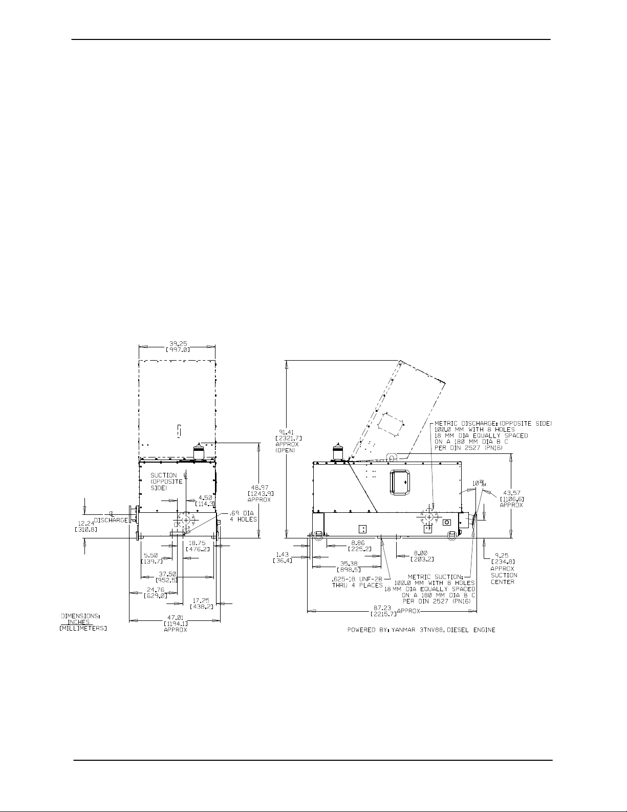
Pump Dimensions
See Figure 1 for the approximate physical dimen-
sions of this pump.
Figure 1. Pump Model PA4E71C−3TNV88−SE
PREINSTALLATION INSPECTION
The pump assembly was inspected and tested before shipment from the factory. Before installation,
inspect the pump for damage which may have occurred during shipment. Check as follows:
a. Inspect the pump for cracks, dents, damaged
threads, and other obvious damage.
b. Check for and tighten loose attaching hard-
ware. Since gaskets tend to shrink after drying, check for loose hardware at mating surfaces.
PAGE B − 1INSTALLATION
Page 9
OM−06244 PA SERIES
c. Carefully read all tags, decals, and markings
on the pump assembly, and perform all duties
indicated. Note that the pump shaft rotates in
the required direction.
Only operate this pump in the direction indicated by the arrow on the pump body
and on the accompanying decal. Otherwise, the impeller could become loosened
from the shaft and seriously damage the
pump.
d. Check levels and lubricate as necessary. Re-
fer to LUBRICATION in the Maintenance and
Repair Manual and perform duties as instructed.
e. If the pump has been stored for more than 12
months, some of the components or lubricants may have exceeded their maximum
shelf life. These must be inspected or re-
placed to ensure maximum pump service.
use in lifting the pump assembly only.
Suction and discharge hoses and pip-
ing must be removed from the pump be-
fore lifting.
Lifting
Pump unit weights will vary depending on the
mounting and drive provided. Check the shipping
tag on the unit packaging for the actual weight, and
use lifting equipment with appropriate capacity.
Drain the pump and remove all customer-installed
equipment such as suction and discharge hoses
or piping before attempting to lift existing, installed
units.
The pump assembly can be seriously
damaged if the chains or cables used to lift
and move the unit are improperly wrapped
around the pump.
Mounting
If the maximum shelf life has been exceeded, or if
anything appears to be abnormal, contact your
Gorman-Rupp distributor or the factory to determine the repair or updating policy. Do not put the
pump into service until appropriate action has
been taken.
POSITIONING PUMP
Use lifting and moving equipment in
good repair and with adequate capacity
to prevent injuries to personnel or damage to equipment. Attach lifting equipment to the lifting device fitted to the
pump. If chains or cable are wrapped
around the pump to lift it, make certain
that they are positioned so as not to
damage the pump, and so that the load
will be balanced. The bail is intended for
Locate the pump in an accessible place as close as
practical to the liquid being pumped. Level mount-
ing is essential for proper operation. The pump
may have to be supported or shimmed to provide
for level operation and eliminate vibration.
For engine driven units, the pump must be posi-
tioned as level as possible to ensure sufficient lubri-
cation and fuel supply to the engine.
If the pump has been mounted on a moveable
base, make certain the base is stationary by setting
the brake and blocking the wheels before attempt-
ing to operate the pump.
If the pump has been mounted on a mov-
able base, do not attempt to operate the
pump unless the unit is level. Be sure
the leveling stands are positioned on a
solid surface, and the wheels are
chocked.
PAGE B − 2 INSTALLATION
Page 10

PA SERIES OM−06244
SUCTION AND DISCHARGE PIPING
Pump performance is adversely effected by increased suction lift, discharge elevation, and friction losses. See the performance curve and operating range shown on Page E-1 to be sure your
overall application allows pump to operate within
the safe operation range.
Materials
Either pipe or hose maybe used for suction and
discharge lines; however, the materials must be
compatible with the liquid being pumped. If hose is
used in suction lines, it must be the rigid-wall, reinforced type to prevent collapse under suction. Using piping couplings in suction lines is not recommended.
Line Configuration
Keep suction and discharge lines as straight as
possible to minimize friction losses. Make minimum use of elbows and fittings, which substantially increase friction loss. If elbows are necessary,
use the long-radius type to minimize friction loss.
dope should be compatible with the liquid being
pumped.
SUCTION LINES
To avoid air pockets which could affect pump prim-
ing, the suction line must be as short and direct as
possible. When operation involves a suction lift, the
line must always slope upward to the pump from
the source of the liquid being pumped; if the line
slopes down to the pump at any point along the
suction run, air pockets will be created.
Fittings
Suction lines should be the same size as the pump
inlet. If reducers are used in suction lines, they
should be the eccentric type, and should be in-
stalled with the flat part of the reducers uppermost
to avoid creating air pockets. Valves are not nor-
mally used in suction lines, but if a valve is used,
install it with the stem horizontal to avoid air pock-
ets.
Strainers
Be certain to use the strainer furnished with the
pump; any spherical solids which pass through the
strainer will also pass through the pump itself.
Connections to Pump
Before tightening a connecting flange, align it exactly with the pump port. Never pull a pipe line into
place by tightening the flange bolts and/or couplings.
Lines near the pump must be independently supported to avoid strain on the pump which could
cause excessive vibration, decreased bearing life,
and increased shaft and seal wear. If hose-type
lines are used, they should have adequate support
to secure them when filled with liquid and under
pressure.
Gauges
The pump is drilled and tapped for installing discharge pressure and vacuum suction gauges. It is
recommended that gauges be installed to monitor
pump performance. Seal the gauge threads with
pipe dope to ensure an airtight seal. Follow the
sealant manufacturer’s recommendations when
selecting and applying the pipe dope. The pipe
If a strainer not furnished with the pump is installed
by the pump user, make certain that the total area
of the openings in the strainer is at least three or
four times the cross section of the suction line, and
that the openings will not permit passage of solids
larger than the solids handling capability of the
pump.
This pump is designed to handle up to 3 inch (76,2
mm) diameter spherical solids.
Sealing
Since even a slight leak will affect priming, head,
and capacity, especially when operating with a
high suction lift, all connections in the suction line
should be sealed with pipe dope to ensure an air-
tight seal. Follow the sealant manufacturer’s rec-
ommendations when selecting and applying the
pipe dope. The pipe dope should be compatible
with the liquid being pumped.
Suction Lines In Sumps
If a single suction line is installed in a sump, it
should be positioned away from the wall of the
PAGE B − 3INSTALLATION
Page 11
OM−06244 PA SERIES
sump at a distance equal to 1 1/2 times the diameter of the suction line.
If there is a liquid flow from an open pipe into the
sump, the flow should be kept away from the suction inlet because the inflow will carry air down into
the sump, and air entering the suction line will reduce pump efficiency.
If it is necessary to position inflow close to the suction inlet, install a baffle between the inflow and the
suction inlet at a distance 1-1/2 times the diameter
of the suction pipe. The baffle will allow entrained
air to escape from the liquid before it is drawn into
the suction inlet.
If two suction lines are installed in a single sump,
the flow paths may interact, reducing the efficiency
of one or both pumps. To avoid this, position the
suction inlets so that they are separated by a distance equal to at least 3 times the diameter of the
suction pipe.
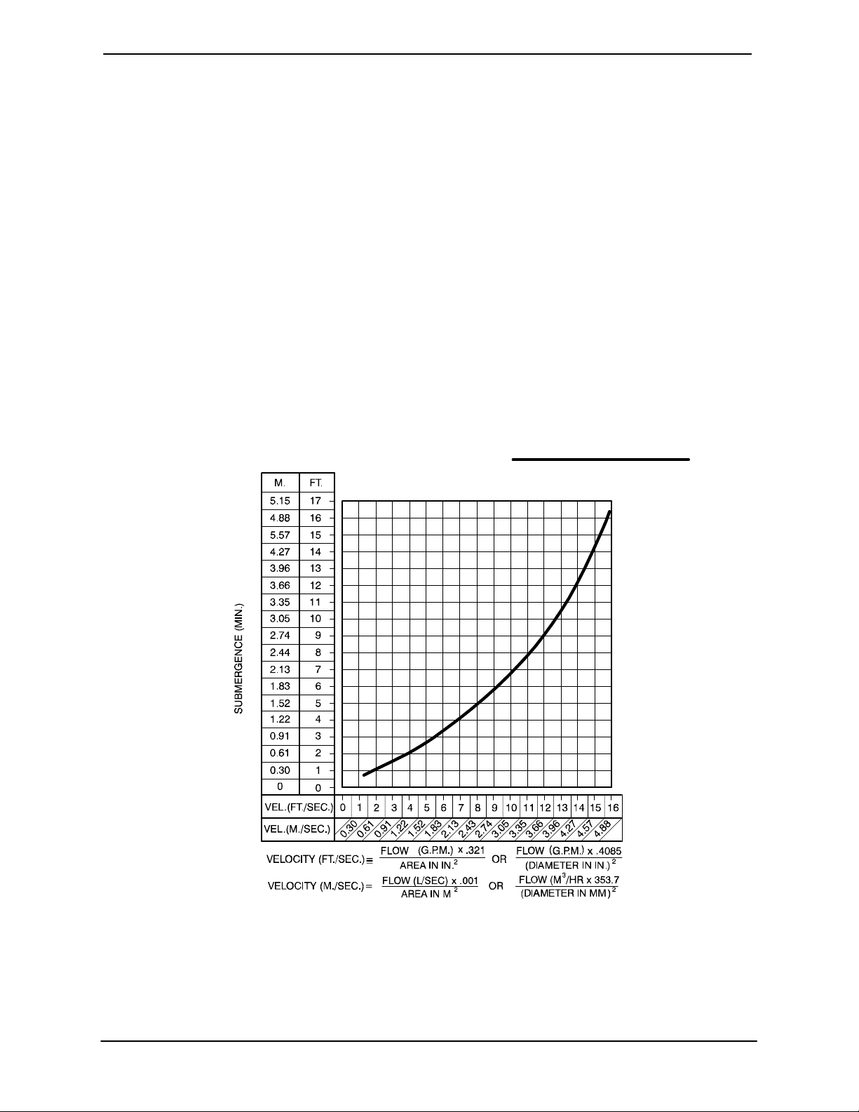
Suction Line Positioning
The depth of submergence of the suction line is
critical to efficient pump operation. Figure 2
shows recommended minimum submergence vs.
velocity.
Although not recommended, the vacuum assisted
priming feature allows the pump to be operated
temporarily in a slurping" application with varying
water levels.
NOTE
The pipe submergence required may be reduced
by installing a standard pipe increaser fitting at the
end of the suction line. The larger opening size will
reduce the inlet velocity. Calculate the required
submergence using the following formula based
on the increased opening size (area or diameter).
Figure 2. Recommended Minimum Suction Line Submergence vs. Velocity
PAGE B − 4 INSTALLATION
Page 12
PA SERIES OM−06244
DISCHARGE LINES
Siphoning
Do not terminate the discharge line at a level lower
than that of the liquid being pumped unless a siphon breaker is used in the line. Otherwise, a siphoning action causing damage to the pump
could result.
Valves
This pump is designed with a check valve in the
discharge line.
If a throttling valve is desired in the discharge line,
use a valve as large as the largest pipe to minimize
friction losses. Never install a throttling valve in a
suction line.
With high discharge heads, it is recommended that
a throttling valve be installed in the discharge line
to protect the pump from excessive shock pressure and reverse rotation when it is stopped.
If the application involves a high discharge
head, gradually close the discharge
throttling valve before stopping the pump.
ALIGNMENT
The alignment of the pump, air compressor and
engine is critical for trouble-free mechanical operation. See Section E, Securing Bearing Housing
And Drive Assembly To Engine in MAINTE-
NANCE AND REPAIR, for details.
Refer to the information which follows for installa-
tion details for the liquid level sensing system pro-
vided with your pump.
Float Switch Installation
The Float Switch autostart system employs either a
single or double float switch, where a bulb raises or
lowers (floats) with the liquid level, thus activating
an enclosed miniature switch. The floats are
equipped with a socket type connector that plugs
into a matching receptacle on the auto-start control
box.
Standard floats are equipped with 50 feet (15,2 m)
of cable.
When installing the floats, note the following:
a. Be sure to provide sufficient room in the wet
well or sump so that floats do not get obstructed or drawn into the suction line. If a flexible suction hose is used, it may be extended
to lay along the bottom of the wet well or sump
and the float can be attached to the hose
above the point where it bends along the bottom. Direct the suction line toward the flow,
and the float(s) away from the flow. If a standpipe is available, attach the float switch cable
to the standpipe in the sump at the approximate desired liquid level.
b. In a single float system, the cable can be teth-
ered to the suction line or standpipe approximately 6 inches (152 mm) above the float.
This setting allows approximately 9 inches
(229 mm) of liquid rise between pump start/
stop. The start/stop interval may be increased
by extending the float end of the cable. The
liquid level in the sump will increase approximately 8 inches (203 mm) between start/stop
intervals for every 6 inches (152 mm) of cable
increase.
AUTO-START
The standard pump is equipped with an auto-start
control system which allows the pump to start and
stop as the liquid level in the wet well or sump rises
and falls.
c. If a double float switch system is used, posi-
tion the Start" float at the desired high water
level in the sump, and the Stop" float at the
desired low water level in the pump.
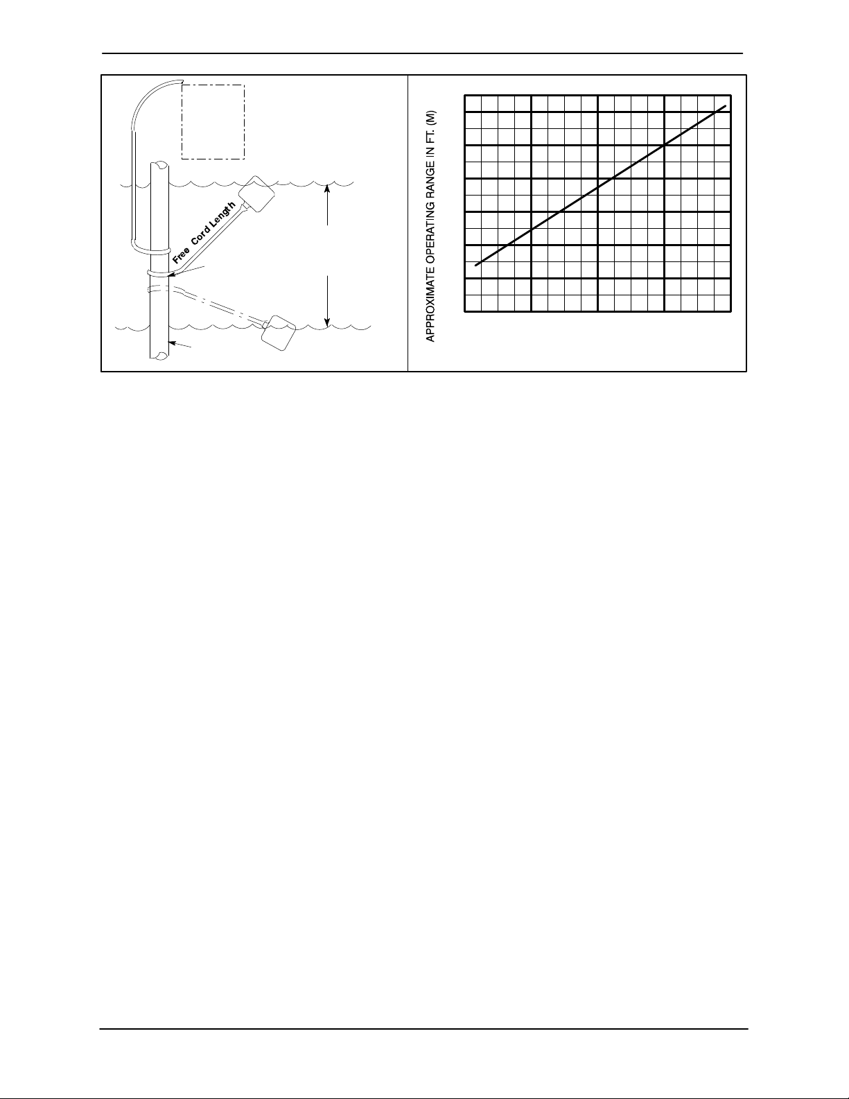
d. Refer to Figure 3 for additional float switch
data.
PAGE B − 5INSTALLATION
Page 13
OM−06244 PA SERIES
ENGINE
CONTROL
BOX
CABLE
TETHER
POINT
1.25" Pipe
(Not Furnished)
ON
(Emptying)
OFF
(Filling)
OPERATING
RANGE
(See Table Below)
OFF
(Emptying)
ON
(Filling)
Figure 3. Float Switch Data
3.0
(0.9)
2.5
(.76)
2.0
(0.6)
1.5
(.46)
1.0
(0.3)
0.5
(.15)
1.0
(0.3)
APPROXIMATE FREE CORD LENGTH IN FT. (M)
2.0
(0.6)
3.0
(0.9)
4.0
(1.2)
PAGE B − 6 INSTALLATION
Page 14
PA SERIES
OM−06244
OPERATION − SECTION C
Review all SAFETY information in Section A.
Follow the instructions on all tags, labels and
decals attached to the pump.
Do not operate an internal combustion
engine in an explosive atmosphere.
When operating an internal combustion
engine in an enclosed area, make sure
exhaust fumes are piped to the outside.
These fumes contain carbon monoxide,
a deadly gas that is colorless, tasteless
and odorless.
OPERATION
cated (see LUBRICATION in MAINTENANCE
AND REPAIR).
The pump will begin to prime upon startup. The air
in the suction line will be discharged from the educ-
tor discharge line. Complete priming is indicated
by a positive discharge pressure reading.
If full priming is not achieved, the discharge check
valve may be malfunctioning. If this occurs, shut
down the pump and consult Maintenance and
Repair, Section E for further details.
STARTING
Check the fuel level and oil levels in the engine, air
compressor, pump bearings and seal housing.
Make sure the pump is level. Lower the jack stands
and chock the wheels, if so equipped.
This pump is designed to handle most
non-volatile, non-flammable liquids
containing specified entrained solids
and corrosives. Do not attempt to pump
volatile, corrosive, or flammable liquids
which may damage the pump or endanger personnel as a result of pump failure.
Pump speed and operating condition
points must be within the continuous performance range shown on the performance curve in Section E on page E−1.
PRIMING
Install the pump and piping as described in INSTALLATION. Make sure that the piping connec-
tions are tight, and that the pump is securely
mounted. Check that the pump is properly lubri-
Make sure the pump is level. Lower jack
stands and chock the wheels, if so
equipped. Use caution when positioning
the skid-mounted unit to prevent damage
to the fuel tank.
This pump is equipped with automatic
liquid level controls, and is subject to
automatic restart. Keep hands and
clothing away from the unit to prevent
injury during automatic operation. Dis-
connect the positive battery cable be-
fore performing any maintenance. Fail-
ure to do so may result in serious per-
sonal injury.
Consult the engine operations manual before at-
tempting to start the unit.
Manual Starting
On initial start-up, set the engine speed at in the
half-throttle position. Turn the keyswitch to ‘MANU-
OPERATION PAGE C − 1
Page 15
OM−06244 PA SERIES
AL’. After the engine starts and the unit is fully
primed, adjust the engine RPM until the desired
flow rate is achieved.
Pump speed and operating condition
points must be within the continuous performance range shown on the curve on
Page E-1.
Automatic Starting
With the float system installed, follow the procedures outlined for manual starting and throttle adjustment. Switch the keyswitch to ‘OFF’ until the
water level rises above the on point for the float system, then turn the keyswitch to the ‘AUTO’ setting.
The unit will run until the float signals the control
that the water in the wet well is at the float off point,
at which time the unit will shut down automatically.
When the float signals the control that the water in
the wet well is at the float on point, the unit will restart automatically, repeating the cycle.
Priming
These fumes contain carbon monoxide,
a deadly gas that is colorless, tasteless
and odorless.
Adjust the engine speed to achieve the desired
output. Do not exceed the factory set engine speed
and system operating pressure. Do not operate
below the recommended operating speed (if appli-
cable).
Never tamper with the governor to gain
more power. The governor establishes
safe operating limits that should not be
exceeded. Refer to the Performance
Curve in the separate Parts List Manual
for the maximum continuous operating
speed for this pump.
OPERATION IN EXTREME HEAT
The safety shutdown system will automatically
stop the unit if engine operating temperature ex-
ceeds design limits. If engine over-temperature
shutdown occurs, allow the unit to cool before re-
starting.
The pump will begin to prime upon startup. The air
in the suction line will be discharged from the eductor discharge line. Complete priming is indicated
by a positive discharge pressure reading.
If full priming is not achieved, the discharge check
valve may be malfunctioning. If this occurs, shut
down the pump and consult the separate Mainte-
nance and Repair manual for further details.
ROUTINE OPERATION
Do not operate an internal combustion
engine in an explosive atmosphere.
When operating an internal combustion
engine in an enclosed area, make sure
exhaust fumes are piped to the outside.
If engine overheating continues, check the engine
lubricant level and viscosity. Consult the engine
operation manual for the recommended lubricant
for operation in extreme heat.
If the unit is being operated in the automatic mode,
adjust the float(s) to allow shorter run and longer
cooling periods, if possible.
This pump is equipped with automatic
liquid level controls, and is subject to
automatic restart. Keep hands and
clothing away from the unit to prevent
injury during automatic operation. Dis-
connect the battery before performing
any maintenance. Failure to do so may
result in serious personal injury.
OPERATIONPAGE C − 2
Page 16
PA SERIES
OM−06244
OPERATIONAL CHECKS
Leakage
Once the pump is fully primed, no leakage should
be visible at pump mating surfaces, or at pump
connections or fittings. Keep all line connections
and fittings tight to maintain maximum pump efficiency.
Pump Vacuum Check
Read the vacuum gauge with the pump primed
and at operation speed. Shut off the pump. The
vacuum gauge reading will immediately drop proportionate to static suction lift, and should then stabilize. If the vacuum reading falls off rapidly after
stabilization, an air leak exists. Before checking for
the source of the leak, check the point of installation of the vacuum gauge.
Liquid Temperature And Overheating
plug to prevent injury to personnel from
hot liquid.
Strainer Check
Check the strainer regularly, and clean it as neces-
sary. The strainer should also be checked if pump
flow rate begins to drop. Monitor and record the
vacuum suction gauge readings regularly to detect
strainer blockage.
Never introduce air or steam pressure into the
pump casing or piping to remove a blockage. This
could result in personal injury or damage to the
equipment. If backflushing is absolutely neces-
sary, liquid pressure must be limited to 50% of the
maximum permissible operating pressure shown
on the pump performance curve.
STOPPING
Manual Stopping
The maximum liquid temperature for this pump is
160 F (71C). Do not apply it at a higher operating
temperature.
Overheating can occur if operated with the valves
in the suction or discharge lines closed. Operating
against closed valves could bring the liquid to a
boil, build pressure, and cause the pump to rupture or explode. If overheating occurs, stop the
pump immediately and allow it to completely cool
before servicing it. Approach any over-heated
pump cautiously.
Allow an over-heated pump to completely cool before servicing. Do not remove plates, covers, gauges, or fittings
from an overheated pump. Liquid within
the pump can reach boiling temperatures, and vapor pressure within the
pump can cause parts being disengaged to be ejected with great force. After the pump cools, drain the liquid from
the pump by removing the casing drain
plug. Use caution when removing the
Never halt the flow of liquid suddenly. If the liquid
being pumped is stopped abruptly, damaging
shock waves can be transmitted to the pump and
piping system. Close all connecting valves slowly.
Reduce the throttle speed slowly and allow the en-
gine to idle briefly before stopping.
In the manual mode, reduce the throttle speed
slowly, and allow the engine to idle briefly before
switching the HAND-OFF-AUTO switch to ‘OFF’.
If the application involves a high discharge
head, gradually close the discharge
throttling valve before stopping the pump.
After stopping the pump, switch off the engine igni-
tion and remove the key to ensure that the pump
will remain inoperative.
Automatic Stopping
In the automatic mode, the pump will stop when
the liquid in the wet well or sump lowers and acti-
vates the Off" float switch(s). The pump will restart
OPERATION PAGE C − 3
Page 17

OM−06244 PA SERIES
automatically when the liquid rises and activates
the On" float switch(s).
Safety Shutdown System
The unit is equipped with a safety system to automatically shut down the engine under certain conditions. The engine will automatically shut down:
1. If the engine exceeds its safe operating temperature.
2. If the engine oil pressure drops below design
limits.
3. If the engine fails to start within a pre-set period of time.
4. If the engine speed exceeds the safe operating range.
5. If the engine fan belt breaks.
Lights on the control panel will indicate which of the
safety features has caused the engine to shut
down.
Should any of the safety features cause the engine
to shut down, the cause must be determined and
corrected before putting the unit back into service.
The engine will not restart until the key switch has
been returned to the ‘OFF’ position for at least 10
seconds.
All safety shutdown features are pre-set at the factory for optimum performance and safety; do not
attempt to adjust these settings.
PERIODIC CHECKS
Seal Cavity And Bearing Lubrication
Both the seal and bearing cavities were fully lubricated at the factory. Check the lubrication levels
before startup, and regularly thereafter as indicated in Section E, Maintenance and Repair.
When lubrication is required, use only SAE No. 30
non-detergent oil.
Bearing Temperature Check
Bearings normally run at higher than ambient temperatures because of heat generated by friction.
Temperatures up to 160F (71C) are considered
normal for bearings, and they can operate safely to
at least 180F (82C).
Checking bearing temperatures by hand is inaccurate. Bearing temperatures can be measured accurately by placing a contact-type thermometer
against the housing. Record this temperature for
future reference.
A sudden increase in bearing temperatures is a
warning that the bearings are at the point of failing
to operate properly. Make certain that the bearing
lubricant is of the proper viscosity and at the correct level (see LUBRICATION in Section E, Main-
tenance and Repair). Bearing overheating can
also be caused by shaft misalignment and/or excessive vibration.
When pumps are first started, the bearings may
seem to run at temperatures above normal. Continued operation should bring the temperatures
down to normal levels.
Never disconnect any of the safety shutdown features; this will void the warranty and could result in serious damage to
the unit and/or injury to personnel. Safety shutdown features are pre-set at the
factory; do not attempt to adjust any of
the settings. Determine the cause of
shutdown before putting the unit back
into service. Consult the factory for additional information.
Air Compressor
The air compressor was lubricated for test at the
factory. However, always check the lubrication level before startup.
Consult the manual accompanying the air compressor and perform all duties and checks as indicated.
Additional Checks
See Page D−4 and perform all recommended preventive maintenance checks applicable to your
particular unit.
OPERATIONPAGE C − 4
Page 18

PA SERIES
OM−06244
Consult the manual accompanying the engine and
perform any and all routine checks recommended
by the engine manufacturer.
COLD WEATHER PRESERVATION
In below freezing conditions, drain the pump to
prevent damage from freezing. Also, clean out any
solids by flushing with a hose. Operate the pump
for approximately one minute; this will remove any
remaining liquid that could freeze the pump rotating parts. If the pump will be idle for more than a
few hours, or if it has been pumping liquids containing a large amount of solids, drain the pump,
and flush it thoroughly with clean water. To prevent
large solids from clogging the drain port and preventing the pump from completely draining, insert
a rod or stiff wire in the drain port, and agitate the
liquid during the draining process. Clean out any
remaining solids by flushing with a hose.
OPERATION PAGE C − 5
Page 19

PA SERIES
OM−06244
TROUBLESHOOTING − SECTION D
Review all SAFETY information in Section A.
Before attempting to open or service the
pump:
1. Familiarize yourself with this manual.
2. Shut down the engine and disconnect the positive battery cable to
ensure that the pump will remain
inoperative.
3. Allow the pump to completely cool
if overheated.
4. Check the temperature before
opening any covers, plates, or
plugs.
5. Close the suction and discharge
valves.
6. Vent the pump slowly and cautiously.
7. Drain the pump.
This pump is equipped with an automatic starting system, and is subject to automatic restart. Keep hands and clothing away from the unit to prevent injury
during automatic operation. Disconnect
the positive battery cable before performing any maintenance. Failure to do
so may result in serious personal injury.
TROUBLE POSSIBLE CAUSE PROBABLE REMEDY
PUMP FAILS TO
PRIME
PUMP STOPS OR
FAILS TO DELIVER
RATED FLOW OR
PRESSURE
Discharge check valve contaminated, damaged, or unable to seat.
Air leak in suction line. Correct leak.
Lining of suction hose collapsed. Replace suction hose.
Leaking or worn seal or pump gasket. Check pump vacuum. Replace
Suction lift or discharge head too high. Check piping installation and install
Air compressor damaged or belts broken.
Strainer clogged. Check strainer and clean if neces-
Eductor clogged. Check and clean eductor.
Air leak in suction line. Correct leak.
Lining of suction hose collapsed. Replace suction hose.
Leaking or worn seal or pump gasket. Check pump vacuum. Replace
Clean or replace check valve.
leaking or worn seal or gasket.
bypass line if needed. See INSTAL-
LATION.
Check and repair/replace.
sary.
leaking or worn seal or gasket.
TROUBLESHOOTING PAGE D − 1
Page 20

OM−06244
TROUBLE POSSIBLE CAUSE PROBABLE REMEDY
PA SERIES
PUMP STOPS OR
FAILS TO DELIVER
RATED FLOW OR
PRESSURE (cont.)
PUMP REQUIRES
TOO MUCH
POWER
Strainer clogged.
Discharge check valve clogged.
Suction intake not submerged at
proper level or sump too small.
Impeller or other wearing parts worn
or damaged.
Discharge head too high.
Suction lift too high.
Pump speed too slow. Check engine output; consult en-
Belt or flexible coupling broken. Check and replace as necessary.
Pump speed too high. Check engine output.
Extreme ambient temperature. Reduce pump output.
Discharge head too low.
Fuel filter clogged. Check & replace often in extreme
Check strainer and clean if necessary.
Check and clean check valve.
Check installation and correct
submergence as needed.
Replace worn or damaged parts.
Check that impeller is properly
centered and rotates freely.
Free impeller of debris.Impeller clogged.
Install bypass line.
Measure lift w/vacuum gauge. Reduce lift and/or friction losses in
suction line.
gine operation manual.
Adjust discharge valve.
operating conditions.
PUMP CLOGS
FREQUENTLY
EXCESSIVE NOISE
Dilute if possible.Liquid solution too thick.
Check and replace as required.Fuel contaminated.
Pump or jack shaft bearing(s) frozen. Disassemble, check and replace
bearing(s) as required..
Discharge flow too slow.
Suction check valve or foot valve
clogged or binding.
Liquid solution too thick.
Cavitation in pump. Reduce suction lift and/or friction
Pumping entrained air.
Impeller clogged or damaged.
Open discharge valve fully to increase flow rate, and run engine at
maximum governed speed.
Clean valve.
Dilute if possible.
losses in suction line. Record vacuum and pressure gauge readings
and consult local representative or
factory.
Locate and eliminate source of air
bubble.
Secure mounting hardware.Pump or drive not securely mounted.
Clean out debris; replace damaged
parts.
TROUBLESHOOTINGPAGE D − 2
Page 21

PA SERIES
TROUBLE POSSIBLE CAUSE PROBABLE REMEDY
OM−06244
BEARINGS RUN
TOO HOT
Bearing temperature is high, but
within limits.
Low or incorrect lubricant.
Suction and discharge lines not properly supported.
Excessive tension on drive belt.
PREVENTIVE MAINTENANCE
Since pump applications are seldom identical, and
pump wear is directly affected by such things as
the abrasive qualities, pressure and temperature
of the liquid being pumped, this section is intended
only to provide general recommendations and
practices for preventive maintenance. Regardless
of the application however, following a routine preventive maintenance schedule will help assure
trouble-free performance and long life from your
Gorman-Rupp pump. For specific questions concerning your application, contact your GormanRupp distributor or the Gorman-Rupp Company.
Record keeping is an essential component of a
good preventive maintenance program. Changes
in suction and discharge gauge readings (if so
Check bearing temperature regularly to monitor any increase.
Check for proper type and level of
lubricant.
Check piping installation for proper
support.
Align drive properly.Drive misaligned.
Check belt tension. Adjust as
required.
equipped) between regularly scheduled inspections can indicate problems that can be corrected
before system damage or catastrophic failure occurs. The appearance of wearing parts should also
be documented at each inspection for comparison
as well. Also, if records indicate that a certain part
(such as the seal) fails at approximately the same
duty cycle, the part can be checked and replaced
before failure occurs, reducing unscheduled down
time.
For new applications, a first inspection of wearing
parts at 250 hours will give insight into the wear rate
for your particular application. Subsequent inspections should be performed at the intervals shown
on the chart below. Critical applications should be
inspected more frequently.
TROUBLESHOOTING PAGE D − 3
Page 22

OM−06244
PA SERIES
Preventive Maintenance Schedule
Service Interval*
Item
General Condition (Temperature, Unusual
Noises or Vibrations, Cracks, Leaks,
Loose Hardware, Etc.) I
Pump Performance (Gauges, Speed, Flow) I
Bearing Lubrication I R
Seal Lubrication (And Packing Adjustment,
If So Equipped) I R
V-Belts (If So Equipped) I
Air Release Valve Plunger Rod (If So Equipped) I C
Front Impeller Clearance (Wear Plate) I
Rear Impeller Clearance (Seal Plate) I
Check Valve I
Pressure Relief Valve (If So Equipped) C
Pump and Driver Alignment I
Shaft Deflection I
Bearings I
Bearing Housing I
Piping I
Driver Lubrication − See Mfgr’s Literature
Daily Weekly Monthly Semi-
Annually
Annually
Legend:
I = Inspect, Clean, Adjust, Repair or Replace as Necessary
C = Clean
R = Replace
* Service interval based on an intermittent duty cycle equal to approximately 4000 hours annually.
Adjust schedule as required for lower or higher duty cycles or extreme operating conditions.
TROUBLESHOOTINGPAGE D − 4
Page 23

PA SERIES
OM−06244
PUMP MAINTENANCE AND REPAIR − SECTION E
MAINTENANCE AND REPAIR OF THE WEARING PARTS OF THE PUMP WILL MAINTAIN PEAK
OPERATING PERFORMANCE.
STANDARD PERFORMANCE FOR PUMP MODEL PA4E71C−3TNV88−SE
Based on 70F (21C) clear water at sea level
with minimum suction lift. Since pump installations
are seldom identical, your performance may be different due to such factors as viscosity, specific
gravity, elevation, temperature, and impeller trim.
Contact the Gorman-Rupp Company to verify performance or part numbers.
Pump speed and operating condition
If your pump serial number is followed by an N",
your pump is NOT a standard production model.
MAINTENANCE & REPAIR PAGE E − 1
points must be within the continuous performance range shown on the curve.
Page 24

OM−06244 PA SERIES
PARTS PAGE
SECTION DRAWING
Figure 1. Pump Model PA4E71C−3TNV88−SE
MAINTENANCE & REPAIRPAGE E − 2
Page 25

PA SERIES
OM−06244
Pump Model PA4E71C−3TNV88−SE
PARTS LIST
(From S/N 1416614 Up)
ITEM
NO.
1 PUMP SUBASSY 46133−755 −−− 1
3 DRIVE ASSY 44162−181 −−− 1
15 HEX NUT D10 15991 13
16 LOCK WASHER J10 15991 21
17 HEX HD CAPSCREW B1006−1/2 15991 6
45 FLAT WASHER K10 15991 15
46 HEX HD CAPSCREW B1007 15991 2
47 SUCT SPOOL BRKT 34165−008 15080 1
48 FLAT WASHER K08 15991 8
49 HEX HD CAPSCREW B0806 15991 1
50 STREET ELBOW RS12 11999 1
60 LOCK WASHER J08 15991 1
PART NAME
PART
NUMBER
MAT’L
CODE
QTY
MAINTENANCE & REPAIR PAGE E − 3
Page 26

OM−06244 PA SERIES
SECTION DRAWING
Figure 2. Pump Model PA4E71C−3TNV88−SE
MAINTENANCE & REPAIRPAGE E − 4
Page 27

PA SERIES
OM−06244
Pump Model PA4E71C−3TNV88−SE
PARTS LIST
(From S/N 1416614 Up)
ITEM
NO.
2 YANMAR 3TNV88 ENGINE 29239−062 −−− 1
16 LOCK WASHER J10 15991 21
18 MUFFLER BLANKET KIT 29334−299 −−− 1
19 MUFFLER CLAMP 29334−257 −−− 1
20 MUFFLER 29334−195 −−− 1
21 MUFFLER CLAMP 29334−257 −−− 1
22 EXHAUST PIPE 31911−005 15000 1
23 MUFFLER SUPPORT ASSY 41881−998 24150 1
24 HEX HD CAPSCREW 22645−131 −−− 2
25 LOCK WASHER J05 15991 27
26 FLAT WASHER K05 15991 25
27 HEX HD CAPSCREW B1006S 15991 4
PART NAME
PART
NUMBER
MAT’L
CODE
QTY
MAINTENANCE & REPAIR PAGE E − 5
Page 28

OM−06244 PA SERIES
SECTION DRAWING
Figure 3. Pump Model PA4E71C−3TNV88−SE
MAINTENANCE & REPAIRPAGE E − 6
Page 29

PA SERIES
OM−06244
Pump Model PA4E71C−3TNV88−SE
PARTS LIST
(From S/N 1416614 Up)
ITEM
NO.
4 HEX HD CAPSCREW B0403−1/2 15991 12
5 FLAT WASHER K04 15991 12
6 FUEL PICKUP 29332−145 −−− REF
7 UNVENTED FUEL GAUGE 29332−136 −−− 1
8 EDUCTOR HOSE ASSY 46341−030 −−− 1
9 CONT PANEL BRKT 34518−025 15080 1
10 CONTROL PANEL 29284−012 −−− 1
11 HEX NUT D06 15991 17
12 LOCK WASHER J06 15991 17
13 HEX HD CAPSCREW B0605−1/2 15991 2
14 FUEL TANK VENT ASSY 46341−819 −−− 1
15 HEX NUT D10 15991 13
16 LOCK WASHER J10 15991 21
17 HEX HD CAPSCREW B1006−1/2 15991 6
25 LOCK WASHER J05 15991 27
26 FLAT WASHER K05 15991 25
28 LIFTING BAIL TOP SEAL 33311−054 19460 1
29 LIFTING BAIL ASSY 44713−040 24150 1
30 BATTERY BOX ASSY 42432−005 −−− 1
31 FLAT WASHER K06 15991 19
32 THREADED INSERT 21769−159 −−− 3
33 FRNT PANEL MNT BRKT 34268−021 15120 1
34 NEG BATT CABLE ASSY 47311−159 −−− 1
35 POS BATT CABLE ASSY 47311−111 −−− 1
36 FUEL LINE ASSY 46341−818 −−− 1
37 REDIATOR DRAIN ASSY 46342−044 −−− 1
38 OIL DRAIN 46342−051 −−− 1
39 BASE FUEL TANK ASSY 41553−018 24150 1
40 PUMP DRAIN ASSY 46346−322 −−− 1
41 HEX HD CAPSCREW B0504 15991 13
42 AIR INTAKE COVER ASSY 46823−029 −−− 1
43 HEX NUT D04 15991 12
44 LOCK WASHER J04 15991 12
58 4" DOUBLE SIDED TAPE 18666−205 −−− 1
59 PIPE PLUG P08 15079 5
PART NAME
PART
NUMBER
MAT’L
CODE
QTY
MAINTENANCE & REPAIR PAGE E − 7
Page 30

OM−06244 PA SERIES
SECTION DRAWING
Figure 4. Pump Model PA4E71C−3TNV88−SE
MAINTENANCE & REPAIRPAGE E − 8
Page 31

PA SERIES
OM−06244
Pump Model PA4E71C−3TNV88−SE
PARTS LIST
(From S/N 1416614 Up)
ITEM
NO.
4 HEX HD CAPSCREW B0403−1/2 15991 12
25 LOCK WASHER J05 15991 27
26 FLAT WASHER K05 15991 25
41 HEX HD CAPSCREW B0504 15991 13
43 HEX NUT D04 15991 12
44 LOCK WASHER J04 15991 12
52 ENCLOSURE ASSY 42164−021 −−− 1
53 STRUT 29337−524 −−− 2
54 HEX NUT D05 15991 8
55 LOCK WASHER J05 15991 8
56 SAFETY CABLE 41158−846 −−− 1
57 STRIKER PLATE ASSY 41145−014 24150 2
NOT SHOWN:
OPTIONAL:
PART NAME
394" LG RUB SEAL 18668−008 −−− 2
SUCTION STICKER 6588AG −−− 2
DISCHARGE STICKER 6588BJ −−− 2
WARNING DECAL 38816−345 −−− 2
OIL DRAIN LABEL 38816−323 −−− 2
RADIATOR DRAIN LABEL 38816−322 −−− 2
WARNING LABEL 38816−203 −−− 2
PUMP DRAIN LABEL 38816−320 −−− 2
CAUTION DECAL 38816−140 −−− 1
FUEL TANK DRAIN LABEL 38816−321 −−− 1
BRG/SEAL DRAIN LABEL 38816−346 −−− 1
WARNING DECAL 2613FE −−− 2
INSTRUCTION DECAL 38818−144 −−− 1
ENG OPERATING DECAL 38816−347 −−− 1
GUARD WRNING STKR 38816−063 −−− 1
INSTRUCTION TAG 38817−085 −−− 1
NAME PLATE 38818−127 13000 1
DRIVE SCREW BM#04−03 17000 4
G-R DECAL GR06 −−− 2
DRAIN VLV POS DECAL 38817−090 −−− 1
LUBE DECAL 11421A −−− 1
ENGINE STARTUP TAG 38816−269 −−− 1
PRIME AIRE DECAL 38812−078 −−− 2
BATTERY MAINT KIT 48313−802 −−− 1
LOW SULFER FUEL DECAL 38816−196 −−− 1
BATTERY 29331−527 −−− 1
PART
NUMBER
MAT’L
CODE
QTY
MAINTENANCE & REPAIR PAGE E − 9
Page 32

OM−06244 PA SERIES
SECTION DRAWING
Figure 5. Pump Subassembly
ITEM
NO.
1 PUMP END PARTS SEE FIGURE 6 −−− 1
2 CHECK VALVE PARTS SEE FIGURE 7 −−− 1
3 PRIMING CHAMBER PARTS SEE FIGURE 8 −−− 1
4 AIR COMPRESSOR PARTS SEE FIGURE 9 −−− 1
PART NAME
PART
NUMBER
MAT’L
CODE
MAINTENANCE & REPAIRPAGE E − 10
QTY
Page 33

PA SERIES
OM−06244
SECTION DRAWING
Figure 6. Pump End Parts
MAINTENANCE & REPAIR PAGE E − 11
Page 34

OM−06244 PA SERIES
Pump End Parts
PARTS LIST
ITEM
NO.
1 PUMP CASING 38219−306 10000 1
2 REPAIR ROTATING ASSY (SEE FIG. 10) 44163−475 −−− 1
3 PIPE PLUG P12 15079 3
4 PIPE PLUG P08 15079 4
5
6 ROT ASSY ADJ SHIM SET 13130 17040 4
7 O-RING S1674 −−− 1
8 LOCK WASHER J08 15991 8
9 HEX HD CAPSCREW B0806 15991 4
11 ELBOW AG08 11999 1
12 PIPE NIPPLE T0818 15079 1
13 STREET ELBOW 26381−448 −−− 1
14 LOCK WASHER J06 15991 13
15 HEX HD CAPSCREW B0605−1/2 15991 6
16 SUCTION SUPPORT 34266−052 15080 1
17 HEX NUT D10 15991 4
18 HEX HD CAPSCREW B0803 15991 4
19 LOCK COLLAR 38115−551 15001 4
20 ADJUSTING SCREW 31871−070 1500G 4
21 O-RING 25152−246 −−− 1
22 HEX HD CAPSCREW B0604−1/2 15991 4
23 SUCTION ADAPTOR 38641−736 10000 1
24 O-RING 25152−277 −−− 1
25 O-RING 25152−158 −−− 1
26 WEAR PLATE ASSY 46451−762 −−− 1
27 O-RING 25152−178 −−− 1
61 LOCK WASHER J04 15991 19
83 RD HD MACH SCREW X#10−06 15991 2
84 FLAT WASHER K#10 15991 2
85 VALVE BRACKET 34518−028 13000 1
86 LOCK WASHER J#10 15991 2
87 HEX NUT D#10 15991 2
88 HEX HD CAPSCREW B0402−1/2 15991 2
89 HEX NUT D04 15991 4
90 SEAL/BRG CVTY DRAIN (SEE FIG. 14) 46342−045 −−− 1
92 STREET ELBOW RS08 11999 1
93 PIPE NIPPLE T0836 15079 1
94 PIPE ELBOW R08 11999 1
95 REDUCING PIPE BUSHING AP1208 15079 1
99 NIPPLE T0414 15079 2
100 BALL VALVE 26631−022 −−− 2
101 MALE COUPLER 26534−044 −−− 1
102 REDUCING PIPE BUSHING AP0804 14990 1
NOT SHOWN:
PART NAME
O-RING 25152−273 −−− 1
4" LONG DOUBLE-SIDED TAPE 18666−205 −−− 1
PART
NUMBER
MAT’L
CODE
QTY
INDICATES PARTS RECOMMENDED FOR STOCK
MAINTENANCE & REPAIRPAGE E − 12
Page 35

PA SERIES
OM−06244
SECTION DRAWING
Figure 7. Check Valve and Related Parts
ITEM
NO.
4 PIPE PLUG P08 15079 2
14 LOCK WASHER J06 15991 25
17 HEX NUT D10 15991 20
34 PIPE PLUG P04 15079 1
35 LOCK WASHER J10 15991 20
44 STUD C1010 15991 4
45 STUD C1009 15991 8
46 4" CHECK VALVE 26642−124 −−− 1
47 4" METRIC SPOOL FLG 38642−211 10000 1
48 HEX HD CAPSCREW B1010 15991 8
49 GASKET 25113−034 −−− 2
50 ECC REDUCER SPOOL 38642−408 −−− 1
51 GASKET 25113−033 −−− 1
91 PIPE PLUG P20 15079 1
103 FLAT WASHER K10 15991 1
INDICATES PARTS RECOMMENDED FOR STOCK
PART NAME
−FLAPPER 26688−005 −−− 1
−COVER PLATE O-RING 25152−366 −−− 1
PART
NUMBER
MAT’L
CODE
QTY
MAINTENANCE & REPAIR PAGE E − 13
Page 36

OM−06244 PA SERIES
SECTION DRAWING
Figure 8. Priming Chamber and Related Parts
MAINTENANCE & REPAIRPAGE E − 14
Page 37

PA SERIES
OM−06244
Priming Chamber and Related Parts
PARTS LIST
ITEM
NO.
8 LOCK WASHER J08 15991 2
17 HEX NUT D10 15991 8
28 SAFETY CABLE BRACKET 34268−020 13000 1
29 HEX HD CAPSCREW B0807 15991 3
30 LOCK WASHER J08 15991 3
31 PRIMING CHAMBER KIT (SEE FIG. 11) 48275−005 −−− 1
32 GASKET 38689−037 18000 1
33 4" HOPPER SPOOL 38644−802 10000 1
35 LOCK WASHER J10 15991 4
36 HEX HD CAPSCREW B1007 15991 4
37 GASKET 1676GB 20000 1
38 4" NPT FLANGE 1756 10010 1
39 HEX HD CAPSCREW B1011 15991 8
40 PIPE NIPPLE T6444 15079 1
41 4" METRIC FLANGE 38641−315 10010 1
42 COVER PLATE 38244−021 15080 1
43 HEX HD CAPSCREW B0804 15991 2
58 GASKET 38687−053 19060 1
99 PIPE NIPPLE T0414 15079 2
100 BALL VALVE 26631−022 −−− 2
101 MALE COUPLER 26534−044 −−− 2
PART NAME
PART
NUMBER
MAT’L
CODE
QTY
INDICATES PARTS RECOMMENDED FOR STOCK
MAINTENANCE & REPAIR PAGE E − 15
Page 38

OM−06244 PA SERIES
SECTION DRAWING
Figure 9. Air Compressor and Related Parts
MAINTENANCE & REPAIRPAGE E − 16
Page 39

PA SERIES
OM−06244
Air Compressor and RelatedParts
PARTS LIST
ITEM
NO.
10 SHAFT KEY N0604 15990 1
14 LOCK WASHER J06 15991 8
15 HEX HD CAPSCREW B0605−1/2 15991 1
17 HEX NUT D10 15991 12
22 HEX HD CAPSCREW B0604−1/2 15991 2
35 LOCK WASHER J10 15991 4
52 FAN GUARD ASSY 41888−076 24150 2
53 GROMMET 27135−101 −−− 1
54 FAN 26761−013 −−− 1
55 CLAMP W/CUSHION 27111−347 −−− 1
56 FLAT WASHER K06 15991 7
57 AIR COMPRESSOR 26813−113 −−− 1
59 COMPRESSOR BUSHING 31531−022 −−− 1
60 AIR COMPRESSOR SPROCKET 24271−005 −−− 1
61 LOCK WASHER J04 15991 3
62 HEX HD CAPSCREW B0406 15991 3
63 GUARD BRACKET 34127−110 15120 2
64 FAN GUARD 42381−510 2415X 1
65 HEX NUT D06 15991 6
66 HEX HD CAPSCREW B0404 15991 2
67 FLAT WASHER K04 15991 2
68 FRONT BELT GUARD 34718−015 15120 1
69 HEX HD CAPSCREW B0603−1/2 15991 4
70 COMP DRIVE BUSHING 24131−317 −−− 1
71 COG BELT 24186−010 −−− 1
72 HEX HD CAPSCREW 22645−135 −−− 1
73 LOCK WASHER J05 15991 1
74 PUMP SPROCKET 24271−115 −−− 1
75 THREADED ROD 31345−092 1500G 4
76 COMPRESSOR BASE 33659−064 15080 1
77 HEX JAM NUT AT10 15991 4
78 PIPE CAP V04 15079 1
79 PIPE NIPPLE T0418 15079 1
80 STREET ELBOW RS04 11999 1
81 MOUNTING PLATE 33541−078 15080 1
82 HEX HD CAPSCREW B0605 15991 4
89 HEX NUT D04 15991 6
96 HEX HD CAPSCREW B0403−1/2 15991 2
97 HEX HD CAPSCREW 22645−036 −−− 4
98 HEX NUT 22647−006 −−− 4
104 ADAPTOR FITTING 26813−952 −−− 1
PART NAME
PART
NUMBER
MAT’L
CODE
QTY
INDICATES PARTS RECOMMENDED FOR STOCK
MAINTENANCE & REPAIR PAGE E − 17
Page 40

OM−06244 PA SERIES
SECTION DRAWING
Figure 10. 44163−475 Repair Rotating Assembly
MAINTENANCE & REPAIRPAGE E − 18
Page 41

PA SERIES
OM−06244
PARTS LIST
44163−475 Repair Rotating Assembly
ITEM
NO.
1 IMPELLER 38615−108 1102H 1
2 CARTRIDGE SEAL ASSEMBLY 46513−151 −−− 1
3 IMPELLER ADJ SHIM SET 37J 17090 REF
4 SHAFT SLEEVE O-RING 25154−022 −−− REF
5 SEAL PLATE 38272−234 1102H 1
6 SEAL PLATE GASKET 10959G 20000 1
7 OIL SEAL S1352 −−− 1
7A OIL SEAL S1352 −−− 1
7B OIL SEAL S1352 −−− 1
8 LOCK WASHER J08 15991 4
9 HEX HD CAPSCREW B0805−1/2 15991 4
10 BEARING HOUSING 38251−415 10000 1
11 BEARING CAVITY DRAIN PLUG P04 15079 1
11A SEAL CAVITY DRAIN PLUG P04 15079 1
12 VENTED PLUG 4823A 15079 1
13 RED PIPE BUSHING AP0802 15079 1
14 AIR VENT S1530 −−− 1
15 SEAL CAVITY SIGHT GAUGE S1471 −−− 1
15A BEARING CAVITY SIGHT GAUGE S1471 −−− 1
16 PIPE PLUG P12 15079 1
17 INTERMEDIATE GUARD 42381−509 24152 2
18 HEX HD CAPSCREW 21632−934 −−− 8
19 LOCK WASHER J06 15991 8
20 MOUNTING FLANGE 38545−013 11010 1
21 MOUNTING FLANGE GASKET 38683−275 18000 1
22 SNAP RING S442 −−− 1
23 BALL BEARING S375 −−− 1
24 SHAFT KEY N0604 15990 1
25 IMPELLER SHAFT 38514−829 1706H 1
26 BALL BEARING S1088 −−− 1
27 SEAL PLATE O-RING 25152−273 −−− 1
28 ROTATING ASSEMBLY ADJ SHIM SET 13130 17040 4
29 BEARING HOUSING O-RING S1674 −−− 1
30 SHIPPING PLUG 11495B 15079 2
NOT SHOWN:
PART NAME
INSTRUCTION TAG 6588U −−− 1
PART
NUMBER
MAT’L
CODE
QTY
INDICATES PARTS RECOMMENDED FOR STOCK
MAINTENANCE & REPAIR PAGE E − 19
Page 42

OM−06244 PA SERIES
SECTION DRAWING
Figure 11. 48275−005 Priming Chamber Kit
ITEM
NO.
1 PRIMING CHAMBER ASSY 46112−709 −−− 1
2 PIPE BUSHING AP1608 11999 1
3 STREET ELBOW RS08 11999 1
4 BALL VALVE 26631−052 −−− 1
5 STUD C0809 15991 4
6 HEX NUT D08 15991 4
7 LOCK WASHER J08 15991 4
8 GASKET 38687−053 19060 1
9 BAFFLE 31113−011 17000 1
INDICATES PARTS RECOMMENDED FOR STOCK
PART NAME
PART
NUMBER
MAT’L
CODE
MAINTENANCE & REPAIRPAGE E − 20
QTY
Page 43

PA SERIES
OM−06244
SECTION DRAWING
Figure 12. 46112−709 Priming Chamber Assembly
ITEM
NO.
1 PRIMING VALVE 26664−007 −−− 1
2 HEX HD CAPSCREW B0806 15991 8
3 LOCKWASHER J08 15991 8
4 PRIMING VALVE GASKET 38683−657 19060 1
5 PRIMING CHAMBER 38343−020 10000 1
6 STRAINER ASSY 46641−222 17000 1
INDICATES PARTS RECOMMENDED FOR STOCK
MAINTENANCE & REPAIR PAGE E − 21
PART NAME
−ORIFICE BUTTON 26688−021 −−− 1
PART
NUMBER
MAT’L
CODE
QTY
Page 44

OM−06244 PA SERIES
SECTION DRAWING
Figure 13. 44162−181 Drive Assembly
ITEM
NO.
1 DRIVE SPROCKET 24271−110 −−− REF
2 COUPLING ASSEMBLY 24391−114 −−− 1
3 LOCK WASHER 21171−511 −−− 10
4 CAPSCREW 22645−164 −−− 10
5 SOCKET HEAD CAPSCREW 22644−211 −−− 8
6 SHAFT KEY N0604 15990 REF
7 BUSHING 24131−595 −−− 1
8 DRIVE SPROCKET BUSHING 24131−317 −−− REF
PART NAME
PART
NUMBER
MAT’L
CODE
MAINTENANCE & REPAIRPAGE E − 22
QTY
Page 45

PA SERIES
OM−06244
SECTION DRAWING
Figure 14. Seal and Bearing Cavity Drains
ITEM
NO.
190 SWIVEL ELBOW 26571−041 −−− 2
2 SWIVEL 26523−042 −−− 2
3 HOSE CLAMP 26518−642 −−− 6
4 3/8" ID x 10−1/2" LG. HOSE 18513−054 −−− 1
5 SHUTOFF VALVE 26661−407 −−− 1
6 STREET ELBOW RS06 11999 2
7 STREET ELBOW AGS06 11999 1
8 HOSE BARB FITTING 26523−389 −−− 3
9 REDDUCER PIPE BUSHING AP0604 14100 1
10 CONNECTOR S1447 −−− 1
11 HOSE BARB FITTING 26523−015 −−− 1
12 3/8" ID x 17−1/2" LG. HOSE 18513−054 −−− 1
13 REDUCER PIPE BUSHING AP0806 14990 1
14 3/8" ID x 8" LG. HOSE 18513−054 −−− 1
MAINTENANCE & REPAIR PAGE E − 23
PART NAME
PART
NUMBER
MAT’L
CODE
QTY
Page 46

PUMP AND SEAL DISASSEMBLY AND REASSEMBLY
PA SERIESOM−06244
Review all SAFETY information in Section A.
Follow the instructions on all tags, label and decals attached to the pump.
This pump requires little service due to its rugged,
minimum-maintenance design. However, if it becomes necessary to inspect or replace the wearing
parts, follow these instructions which are keyed to
the Sectional Views (see Figures 1 through 9) and
the corresponding Parts Lists. Maintenance and
repair instructions for the engine and air compressor are covered separately in the specific literature
supplied by the manufacturers.
This manual will alert personnel to known procedures which require special attention, to those
which could damage equipment, and to those
which could be dangerous to personnel. However,
this manual cannot possibly anticipate and provide
detailed precautions for every situation that might
occur during maintenance of the unit. Therefore, it
is the responsibility of the owner/maintenance personnel to ensure that only safe, established main-
tenance procedures are used, and that any procedures not addressed in this manual are performed
only after establishing that neither personal safety
nor pump integrity are compromised by such practices.
Before attempting to open or service the
pump:
1. Familiarize yourself with this manual.
2. Shut down the engine and disconnect the positive battery cable to
ensure that the pump will remain
inoperative.
3. Allow the pump to completely cool
if overheated.
4. Check the temperature and make
sure it is cool before opening any
covers, plates, gauges, or plugs.
5. Close the suction and discharge
valves.
6. Vent the pump slowly and cautiously.
7. Drain the pump.
This pump is designed to handle material which could cause illness through direct exposure or emitted fumes. Wear
adequate protective clothing when
working on the pump or piping.
Some pump service functions may be performed
without separating the pump end assembly from
the engine. However, the priming chamber (2, Figure 3) and discharge check valve assembly (1, Figure 3) must be removed to service most pump
components. The following instructions assume
complete disassembly of the pump is required.
Before attempting to service the pump, shut down
the engine and take precautions to ensure that it
will remain inoperative. Close all valves in the suction and discharge lines and drain the pump casing by removing the casing drain plug (20, Figure
5). Clean and reinstall the drain plug.
This pump is equipped with an automatic starting system, and is subject to automatic restart. Keep hands and clothing away from the unit to prevent injury
during automatic operation. Disconnect
the positive battery cable before performing any maintenance. Failure to do
so may result in serious personal injury.
Use only replacement parts provided or
approved by Gorman-Rupp. Use of non-
MAINTENANCE & REPAIRPAGE E − 24
Page 47

PA SERIES
OM−06244
authorized parts may result in damage to
the equipment and/or injury to personnel
and will invalidate the warranty.
Priming Chamber Removal And Disassembly
(Figure 11)
Disconnect the air discharge tubing from the priming chamber assembly (1). Support the priming
chamber assembly using a sling and a suitable lifting device. Remove the hardware (6 and 7) and
separate the priming chamber assembly, gasket
(8) and baffle (9) from the spool (33, Figure 8).
(Figure 12)
Remove the hardware (2 and 3) securing the priming valve (1) to the priming chamber (5). Carefully
lift the valve components from the priming chamber. Remove the gasket (4) and clean the mating
surfaces.
If the priming valve float is stuck or the strainer (6) is
clogged, it can usually be cleaned without further
disassembly.
The only serviceable part of the priming valve is the
orifice button (not shown). If liquid continues to bypass through the priming chamber after adjusting
the orifice button (see Priming Chamber Reas-
sembly and Installation for adjustment), the button may require replacement. To replace the orifice
button, remove one of the e-clips" from the pivot
pin closest to the orifice button and remove the pivot pin. This will allow the linkage to be raised high
enough to access the orifice button.
Remove the hex nut and lockwasher securing the
orifice button to the linkage bar and unscrew the
orifice button from the linkage bar.
The flapper and cover O-ring are the only serviceable parts of the check valve. If the flapper requires
replacement, remove the hardware securing the
cover. Separate the cover and O-ring and remove
the flapper.
Suction Adaptor and Wear Plate Removal
(Figure 6)
The wear plate (26) is easily accessible and may be
serviced by removing the suction adaptor (23). Before attempting to service the pump, see Figure 14
and open the shutoff valve (5) to drain the pump
casing. When the casing is fully drained, close the
shutoff valve.
It is not necessary to remove the hopper spool (33,
Figure 8) or suction extension to remove the suction adaptor. Remove the hardware (14 and 15) securing the suction adaptor to the suction support
bracket (16).
Install two 3/8−16 UNC 2B capscrews (not supplied) in the jacking holes in the suction adaptor,
and use the screws to jack" the suction adaptor
and assembled wear plate from the pump casing
(1). Remove the jacking screws from the suction
adaptor.
Inspect the wear plate and replace it if badly scored
or worn. To remove the wear plate, remove the nuts
(17) and adjusting screws (20) and separate the
wear plate from the suction adaptor.
Inspect the O-rings (24, 25 and 27) and replace
them if damaged or worn.
Separating Pump and Drive Assembly From
Engine
The pump and drive assembly must be separated
from the engine before further disassembly.
Discharge Check Valve Removal and
Disassembly
(Figure 7)
Use lifting and moving equipment in
Support the discharge check valve assembly (46)
using a sling and a suitable lifting device. Remove
the nuts (17) and separate the discharge check
valve assembly and gasket (49) from the eccentric
spool (50).
MAINTENANCE & REPAIR PAGE E − 25
good repair and with adequate capacity
to prevent injuries to personnel or damage to equipment. If slings or chains are
used to move the pump or components,
make sure that the load is balanced;
Page 48

PA SERIESOM−06244
otherwise serious personal injury or
death could result. Suction and discharge hoses and piping must be removed from the pump before lifting.
(Figure 9)
Removing the pump and drive assembly first requires separating the air compressor (57) from the
pump assembly.
Disengage the hardware (14, 22, 56 and 65) and
remove the guard (64). Loosen the uppermost
nuts (17) on the threaded rods (75) enough to be
able to remove the cog belt (71) from the sprocket
(60).
Remove the hardware (14, 56 and 82) securing the
mounting plate (81) to the rotating assembly
mounting flange (20, Figure 10).
It is not necessary to remove the piping from the air
compressor to separate it from the pump. The
hoses are long enough to permit repositioning the
compressor to provide room for pump end removal. Use a sling and suitable lifting device to reposition the compressor to allow room for pump end removal and secure it to prevent movement.
See Figure 3 and remove the air intake cover assembly (42) from the base (39). Support the pump
end using a hoist and sling, and remove the hardware securing the suction support bracket (16, Figure 6) to the base.
(Figure 13)
As the assemblies separate, the flexible portion of
the coupling assembly (2) will remain on the shaft.
To remove the coupling from the shaft, unscrew the
capscrews from the bushing (7). Screw one of the
capscrews into the puller hole in the circumference
of the bushing. As the coupling and bushing separate, remove the bushing and slide the coupling off
the shaft. Remove the bushing key.
It is not necessary to remove the outer ring of the
coupling from the engine flywheel unless the coupling must be replaced. To remove the ring, disengage the hardware (5) securing it to the flywheel.
Remove any leveling shims used under the casing
mounting feet. Tie and tag the shims for ease of
reassembly.
Move the pump end to a clean, well-equipped
shop area for further disassembly.
(Figure 9)
Remove the cog belt (71). Remove the setscrews
from the center of the bushing (70). Reinstall the
one of the setscrews in the tapped hole in the bushing and tighten it to jack" the bushing out of the
drive sprocket (74). Slide the bushing and drive
sprocket off the shaft. Remove the key (10).
Loosening Impeller
(Figure 6)
See Figure 6 and place a clean drip pan under the
outlet for the drain assembly (90). Open the drain
assembly valve and drain the oil from the seal and
bearing cavities. Inspect the seal oil for water, dirt
or a cloudy condition which could indicate seal failure.
After draining the bearing and seal cavities, disconnect the lines for the drain assembly from the
bearing housing (10, Figure 10).
See Figure 13 and remove the hardware (3 and 4)
securing the intermediate to the engine bellhousing. Remove the intermediate guards (17, Figure
10) and separate the assemblies by pulling thepump assembly straight away from the engine.
With the pump end separated from the engine,
wedge a block of wood between the vanes of the
impeller (1, Figure 10) and the pump casing (1) to
prevent rotation.
Install the shaft key (24, Figure 10) in the shaft keyway. Install a lathe dog on the drive end of the shaft
(25, Figure 10) with the V" notch positioned over
the shaft key.
With the impeller rotation still blocked, see Figure
14 and use a long piece of heavy bar stock to pry
against the arm of the lathe dog in a counterclockwise direction (when facing the drive end of the
shaft). Use caution not to damage the shaft or keyway. When the impeller breaks loose, remove the
lathe dog, key and wood block.
MAINTENANCE & REPAIRPAGE E − 26
Page 49

PA SERIES
OM−06244
Turn
Counterclockwise
Lathe Dog Arm
V" Notch
Heavy
Bar Stock
Figure 14. Loosening Impeller
Pump Casing Removal
(Figure 6)
Support the pump casing using a suitable hoist
and sling.
Remove the hardware (8 and 9) securing the pump
casing (1) to the rotating assembly (2). Pull the
pump casing straight away from the rotating assembly to prevent binding on the impeller. Remove
the shims (6) and clean the contacting surfaces.
Impeller Removal
(Figure 10)
With the rotating assembly removed from the
pump casing, unscrew the impeller (1) from the
shaft (25). Use caution when unscrewing the impeller; tension on the shaft seal spring will be released as the impeller is removed. Inspect the impeller and replace if cracked or badly worn.
Remove the impeller adjusting shims (3); tie and
tag the shims, or measure and record their thickness for ease of reassembly.
Shaft Key
Impeller Shaft
Lathe Dog
Setscrew
Use a pair of stiff wires with hooked ends to remove
the stationary element and seat.
An alternate method of removing the stationary
seal components is to remove the hardware (8 and
9) and separate the seal plate (5) and gasket (6)
from the bearing housing (10). Position the seal
plate on a flat surface with the impeller side down.
Use a wooden dowel or other suitable tool to press
on the back side of the stationary seat until the
seat, O-rings, and stationary element can be removed.
Remove the shaft sleeve O-ring (4) and seal plate
O-ring (27).
If no further disassembly is required, refer to Seal
Installation.
Shaft and Bearing Removal and Disassembly
(Figure 10)
When the pump is properly operated and maintained, the bearing housing should not require disassembly. Disassemble the shaft and bearings
only when there is evidence of wear or damage.
Shaft and bearing disassembly in the field
is not recommended. These operations
should be performed only in a properly
equipped shop by qualified personnel.
Disengage the hardware (18 and 19) and remove
the mounting flange (20), gasket (21) and oil seal
(7B). Press the oil seal from the mounting flange.
Place a block of wood against the impeller end of
the shaft (25) and tap the shaft and assembled
bearings (23 and 26) from the bearing housing.
Press the oil seals (7 and 7A) from the bearing
housing.
After removing the shaft and bearings, clean and
inspect the bearings in place as follows.
Seal Removal
(Figures 10 and 15)
Slide the integral shaft sleeve and rotating portion
of the seal off the shaft as a unit.
MAINTENANCE & REPAIR PAGE E − 27
To prevent damage during removal from
the shaft, it is recommended that bearings
Page 50

PA SERIESOM−06244
be cleaned and inspected in place. It is
strongly recommended that the bearings
be replaced any time the shaft and bear-
ings are removed.
Clean the bearing housing, shaft and all component parts (except the bearings) with a soft cloth
soaked in cleaning solvent. Inspect the parts for
wear or damage and replace as necessary.
Most cleaning solvents are toxic and
flammable. Use them only in a well ventilated area free from excessive heat,
sparks, and flame. Read and follow all
precautions printed on solvent containers.
Clean the bearings thoroughly in fresh cleaning
solvent. Dry the bearings with filtered compressed
air and coat with light oil.
Shaft and Bearing Reassembly and Installation
(Figure 10)
Inspect the shaft (25) for distortion, nicks or
scratches, or for thread damage on the impeller
end. Dress small nicks and burrs with a fine file or
emery cloth. Replace the shaft if defective.
Clean and inspect the bearings as indicated in
Shaft And Bearing Removal And Disassembly.
To prevent damage during removal from
the shaft, it is recommended that bearings
be cleaned and inspected in place. It is
strongly recommended that the bearings
be replaced any time the shaft and bear-
ings are removed.
The bearings may be heated to ease installation.
An induction heater, hot oil bath, electric oven, or
hot plate may be used to heat the bearings. Bearings should never be heated with a direct flame or
directly on a hot plate.
Bearings must be kept free of all dirt and
foreign material. Failure to do so will greatly shorten bearing life. Do not spin dry
bearings. This may scratch the balls or
races and cause premature bearing failure.
Rotate the bearings by hand to check for roughness or binding and inspect the bearing balls. If rotation is rough or the bearing balls are discolored,
replace the bearings.
The bearing tolerances provide a tight press fit
onto the shaft and a snug slip fit into the bearing
housing. Replace the bearings, shaft, or bearing
housing if the proper bearing fit is not achieved.
If bearing replacement is required, remove the
snap ring (22) and use a bearing puller to remove
the inboard and outboard bearings from the shaft.
NOTE
If a hot oil bath is used to heat the bearings, both the
oil and the container must be absolutely clean. If
the oil has been previously used, it must be thor-
oughly filtered.
NOTE
Position the inboard bearing (26) on the shaft with
the shield facing toward the impeller end of the
shaft. Position the outboard bearing (23) on the
shaft with the retaining ring on the bearing O.D. to-
ward the drive end of the shaft.
Heat the bearings to a uniform temperature no
higher than 250F (120C) and slide the bearings
onto the shaft, one at a time, until they are fully
seated. This should be done quickly, in one continuous motion, to prevent the bearings from cooling and sticking on the shaft.
After the bearings have been installed and allowed
to cool, check to ensure that they have not moved
away from the shaft shoulders in shrinking. If
movement has occurred, use a suitably sized
MAINTENANCE & REPAIRPAGE E − 28
Page 51

PA SERIES
OM−06244
sleeve and a press to reposition the bearings
against the shaft shoulders.
If heating the bearings is not practical, use a suitably sized sleeve and an arbor (or hydraulic) press
to install the bearings on the shaft.
When installing the bearings onto the
shaft, never press or hit against the outer
race, balls, or ball cage. Press only on the
inner race.
Secure the outboard bearing (23) to the shaft with
the snap ring (22)
Apply a light coating of oil to the lip of the inboard oil
seal (7A) and press it into the bearing housing bore
with the lip positioned as shown in Figure 10, Detail
C. Press the oil seal into the housing until the face is
just flush with the machined surface on the housing.
C. The face of the oil seal should be just flush with
the machined face of the bearing housing.
Apply a light coating of oil to the lip of the oil seal
(7B) and press it into the mounting flange (20) with
the lip positioned as shown in Figure 10, Detail B.
The face of the oil seal should be flush with the
chamfer on the mounting flange bore.
Install the drive flange gasket (21) and secure the
drive flange to the bearing housing with the hardware (18 and 19). Be careful not to damage the lip
of the oil seal on the shaft keyway.
Lubricate the bearings as indicated in LUBRICA-
TION at the end of this section.
Securing Bearing Housing and Drive Assembly
To Engine
(Figure 13)
Install the key (6) in the shaft keyway, making sure
to leave room in the keyway for the coupling key.
Install the drive sprocket (1) and bushing (8) on the
shaft to the dimension shown in Figure 13.
It is recommended that a sleeve be positioned
against the inboard oil seal to prevent the lip of the
oil seal from rolling as the shaft and bearings are
installed in the bearing housing. The O.D. of the
sleeve should be just smaller than the bearing
housing bore, while the I.D. of the sleeve should be
just larger than the O.D. of the lip seal area of the
shaft.
With the lip seal sleeve in place, lubricate the lip
seal area of the shaft, and slide the shaft and assembled bearings into the bearing housing until
the retaining ring on the outboard bearing seats
against the bearing housing. Remove the lip seal
sleeve.
When installing the shaft and bearings into
the bearing bore, push against the outer
race. Never hit the balls or ball cage.
Apply a light coating of oil to the lip of the outboard
oil seal (7) and press it into the bearing housing
with the lip positioned as shown in Figure 10, Detail
Make certain that the drive sprocket is
mounted as shown in Figure 13. This di-
mension is critical. If the drive sprocket is
not properly positioned on the shaft, it will
not align properly with the driven sprocket
on the air compressor, which can cause
premature cog belt failure.
Secure the bushing and sprocket to the shaft by
torqueing the bushing setscrews to 14.6 ft. lbs.
(175 in. lbs. or 2 m. kg.). Install the cog belt (71, Figure 9) over the sprocket and up through the slot in
the mounting flange (20, Figure 10).
Install the key for the bushing (7) in the shaft keyway. Position the flexible portion of the coupling assembly (2) on the shaft as shown in Figure 13.
NOTE
The flexible portion of the coupling must be properly positioned on the shaft. The heads of the capscrews in the center of the coupling must be posi-
tioned away from the pump.
MAINTENANCE & REPAIR PAGE E − 29
Page 52

PA SERIESOM−06244
Align the keyway in the bushing (7) with the bushing key, and slide it onto the shaft to the dimension
shown in Figure 13. Rotate the flexible portion of
the coupling until the tapped holes for the two setscrews align with those in the bushing, and install
the capscrews.
Make certain that the flexible portion of the
coupling is mounted as shown in Figure
13. This dimension is critical. If the coupling is not properly positioned on the
shaft, the coupling parts may not fully engage, or a pre-load condition can cause
premature bearing failure.
The end of the shaft must extend 1.38
inches (35 mm) from the face of the cou-
pling. This will allow the two portions of the
coupling to fully engage when the intermediate is secured to the engine bellhousing,
without pre-loading the bearings.
With the flexible portion of the coupling and the
bushing properly positioned on the shaft, tighten
the capscrews in an alternating sequence until the
bushing and coupling are fully secured. Torque the
capscrews to 9 ft. lbs. (108 in. lbs. or 1,2 m. kg.).
Install the intermediate guards (17, Figure 10), and
secure the mounting flange to the engine bellhousing with the previously removed hardware (3 and
4).
(Figure 9)
Use a suitable hoist and sling to position the air
compressor (57) on the mounting flange (20, Figure 10) and secure it to the mounting flange with
the previously removed hardware (14, 56 and 82).
Slide the cog belt (71) over the air compressor driven sprocket (60). Turn the uppermost nuts (17) on
the threaded rods (75) evenly in a cross pattern to
tighten the cog belt on the sprockets. Do not overtighten the cog belt.
NOTE
Tension on the cog belt should be enough so the
belt feels snug or taut. Avoid over-tensioning the
belt. To check belt tension, finish reassembling the
pump, then start the unit. A belt that is too loose will
jump teeth" under load. If this occurs, gradually increase the belt tension until satisfactory operation
is achieved.
Reinstall the guard (64) and secure it with the hardware (14, 22, 56 and 65).
(Figure 6)
If the complete coupling assembly is being replaced, apply ‘Loctite Retaining Compound No.
242’ or equivalent to the threads of the hardware
(5), and secure the outer ring of the coupling to the
engine flywheel by torquing the hardware to 16 ft.
lbs. (192 in. lbs. or 2,2 m. kg.).
Using a suitable lifting device, position the assembled drive and rotating assembly so the flexible portion of the coupling seats inside the outer
ring attached to the engine flywheel.
NOTE
To ease installation, lightly lubricate the rubber portion of the coupling with a non-petroleum based
lubricant such as vegetable oil or glycerin, or a silicon-based lubricant such as WD40" or equivalent.
Do not use petroleum-based lubricants, or any other substance which may soften or otherwise damage the rubber.
Re-connect the lines for the drain assembly (90) to
the drain ports in the bearing housing (29, Figure
10). Be sure to connect the correct drain line to the
corresponding drain port (seal or bearing cavity).
Seal Reassembly and Installation
(Figures 10, 15, 16 and 17)
Most cleaning solvents are toxic and
flammable. Use them only in a well ventilated area free from excessive heat,
sparks, and flame. Read and follow all
precautions printed on solvent containers.
Clean the seal cavity and shaft with a cloth soaked
in fresh cleaning solvent. Inspect the stationary
seat bore in the seal plate for dirt, nicks and burrs,
MAINTENANCE & REPAIRPAGE E − 30
Page 53

PA SERIES
OM−06244
and remove any that exist. The stationary seat bore
must be completely clean before installing the
seal.
A new seal assembly should be installed
any time the old seal is removed from the
RETAINER
SPRING
IMPELLER
IMPELLER
SHIMS
IMPELLER
SHAFT
ROTATING
BELLOWS
ELEMENT
pump. Wear patterns on the finished faces
cannot be realigned during reassembly.
Reusing an old seal could result in premature failure.
To ease installation of the seal, lubricate the shaft
sleeve O-ring and the external stationary seat Oring with a very small amount of light lubricating oil.
See Figure 15 for seal part identification.
SEAL PLATE
O-RINGS
SLEEVE
O-RING
INTEGRAL
STATIONARY
ELEMENT
SHAFT
SLEEVE
SPRING
CENTERING
WASHER
DRIVE BAND
Figure 15. 46513−151 Cartridge Seal Assembly
This seal is not designed for operation at
temperatures above 160F (71C). Do not
use at higher operating temperatures.
If the seal plate (5) was removed, install the seal
plate gasket (6). Position the seal plate over the
shaft and secure it to the bearing housing with the
hardware (8 and 9).
SHEAR
RING
(SHEARED)
STATIONARY
SEAT
To prevent damaging the shaft sleeve O-ring (4) on
the shaft threads, stretch the O-ring over a piece of
tubing. The I.D. of the tubing must be slightly larger
than the O.D. of the shaft. To ease installation, the
tubing wall should be as thin as possible. The
length should be long enough to cover the threads
on the end of the shaft. Slide the tube over the shaft
threads, then slide the O-ring off the tube and onto
the shaft. Remove the tube, and continue to slide
the O-ring down the shaft until it seats against the
shaft shoulder.
MAINTENANCE & REPAIR PAGE E − 31
Page 54

PA SERIESOM−06244
When installing a new cartridge seal assembly,
remove the seal from the container, and remove
the mylar storage tabs (if so equipped) from between the seal faces.
New cartridge seal assemblies may be
equipped with mylar storage tabs between
the seal faces. These storage tabs must be
removed before installing the seal.
Lubricate the external stationary seat O-ring with
light oil. Slide the seal assembly onto the shaft until
the external stationary seat O-ring engages the
bore in the seal plate.
Clean and inspect the impeller as described in Im-
peller Installation and Adjustment. Install half of
the set of impeller shims (3) provided with the seal,
and screw the impeller onto the shaft until it is
seated against the seal (see Figure 16).
O-RING ENGAGED
WITH SEAL PLATE
BORE
to slide down the shaft until seated against the
shaft shoulder. Continue to screw the impeller onto
the shaft until the impeller, shims, and sleeve are
fully seated against the shaft shoulder (see Figure
17).
STATIONARY SEAT
FULLY SEATED IN
SEAL PLATE BORE
SHEAR RING
(SHEARED)
Figure 17. Seal Fully Installed
Measure the impeller-to-seal plate clearance and
add or remove impeller adjusting shims to obtain
the proper clearance as described in Impeller In-
stallation and Adjustment.
If necessary to reuse an old seal in an emer-
gency, carefully separate the rotating and stationary seal faces from the bellows retainer and stationary seat.
SHEAR RING
(UNSHEARED)
Figure 16. Seal Partially Installed
Continue to screw the impeller onto the shaft. This
will press the stationary seat into the seal plate
bore.
NOTE
A firm resistance will be felt as the impeller presses
the stationary seat into the seal plate bore.
As the stationary seat becomes fully seated, the
seal spring compresses, and the shaft sleeve will
break the nylon shear ring. This allows the sleeve
A new seal assembly should be installed
any time the old seal is removed from the
pump. Wear patterns on the finished faces
cannot be realigned during reassembly.
Reusing an old seal could result in premature failure.
Handle the seal parts with extreme care to prevent
damage. Be careful not to contaminate precision
finished faces; even fingerprints on the faces can
shorten seal life. If necessary, clean the faces with a
non-oil based solvent and a clean, lint-free tissue.
Wipe lightly in a concentric pattern to avoid
scratching the faces.
Carefully wash all metallic parts in fresh cleaning
solvent and allow to dry thoroughly.
MAINTENANCE & REPAIRPAGE E − 32
Page 55

PA SERIES
OM−06244
Apply a small amount of ‘Never-Seez’ or equivalent
anti-lock compound on the shaft threads. Screw
the impeller onto the shaft until tight.
Do not attempt to separate the rotating
portion of the seal from the shaft sleeve
when reusing an old seal. The rubber bellows will adhere to the sleeve during use,
and attempting to separate them could
damage the bellows.
Inspect the seal components for wear, scoring,
grooves, and other damage that might cause leakage. Inspect the integral shaft sleeve for nicks or
cuts on either end. If any components are worn, or
the sleeve is damaged, replace the complete seal;
never mix old and new seal parts.
Install the stationary seal element in the stationary
seat. Press this stationary subassembly into the
seal plate bore until it seats squarely against the
bore shoulder. A push tube made from a piece of
plastic pipe would aid this installation. The I.D. of
the pipe should be slightly larger than the O.D. of
the shaft sleeve.
Slide the rotating portion of the seal (consisting of
the integral shaft sleeve, spring centering washer,
spring, bellows and retainer, and rotating element)
onto the shaft until the seal faces contact.
Proceed with Impeller Installation and Adjust-
ment.
Impeller Installation And Adjustment
(Figure 10)
NOTE
At the slightest sign of binding, immediately back
the impeller off, and check the threads for dirt. Do
not try to force the impeller onto the shaft.
A clearance of .025 to .040 inch (0,64 to 1,02 mm)
between the impeller and the seal plate is necessary for maximum pump efficiency. Measure this
clearance and add or remove impeller adjusting
shims as required.
Pump Casing Installation
(Figure 10)
Lubricate the O-rings (31 and 32) with light grease,
and install them in the grooves in the bearing housing and seal plate. Slide the pump casing over the
rotating assembly. Be careful not to damage the
O-rings.
Install the adjusting shims (22) and secure the
pump casing to the rotating assembly with the
hardware (29 and 30).
Wear Plate and Suction Adaptor Installation
(Figure 10)
If the wear plate (5) was removed for replacement,
install new O-rings (33 and 41) on the wear plate
and lubricate them with light grease. Slide the wear
plate studs through the holes in the suction adaptor (64). Press the wear plate into the suction adaptor until fully seated.
Inspect the impeller (1) and replace it if cracked or
badly worn.
The shaft and impeller threads must be
completely clean before reinstalling the impeller. Even the slightest amount of dirt on
the threads can cause the impeller to seize
to the shaft, making future removal difficult
or impossible without damage to the impeller or shaft.
MAINTENANCE & REPAIR PAGE E − 33
Install new O-rings (40 and 45) in the grooves in the
suction adaptor and lubricate them with light
grease. Clean any scale or debris from the contacting surfaces in the pump casing that might interfere or prevent a good seal with the suction adaptor.
Slide the suction adaptor and wear plate into the
pump casing. Secure the suction adaptor to the
suction support bracket (42) and pump casing
with the hardware (10 and 48). Reinstall the remaining suction adaptor hardware (10 and 62). Secure the suction adaptor bracket to the base with
the previously removed hardware.
Page 56

PA SERIESOM−06244
Screw the four adjusting screws (43) into the
tapped holes in the suction adaptor until they
touch the wear plate. Use the lock collars (44) to
turn the adjusting screws in an alternating sequence until the wear plate just touches the impeller.
Position the lock collars over the adjusting screws
so the holes in the collars for the locking screws
(46) align approximately with the corresponding
holes in the suction cover. Use the lock collars to
index the adjusting screws three detents counterclockwise. Remove the lock collars, index them
clockwise until the holes in the collars for the locking screws realign with the corresponding holes in
the suction adaptor and reinstall them on the adjusting screws.
Secure the wear plate to the suction adaptor by
installing the nuts (34). Secure the locking collars
to the back cover plate with the hardware (30 and
46).
Be sure the wear plate does not scrape against the
impeller.
Over time it may be necessary to repeat the adjustment process to compensate for normal wear between the impeller and wear plate. When all of the
adjustment has been used on the suction side of
the pump, an additional 0.125 inch (3,2 mm) of adjustment may be obtained by removing the rotating assembly adjusting shims (75).
Allow an installed pump to completely cool before
draining liquid from the pump casing. Disengage
the hardware (29 and 30), remove the rotating assembly adjusting shims, then reinstall the hardware securing the rotating assembly to the pump
casing. Perform the suction adaptor adjustment
procedure described above to obtain the proper
face clearance.
Install the valve cover O-ring and secure the cover
to the body with the previously removed hardware.
Apply a small amount of light grease to the discharge flange gasket to hold it in place and position it against the pump casing flange. Support the
discharge check valve assembly using a sling and
a suitable lifting device. Using the previously removed hardware, secure the discharge check
valve assembly and flange gasket (49) to the eccentric reducer spool (50).
Priming Chamber Assembly And Installation
(Figure 12)
Clean and inspect the components of the priming
valve (1). Inspect the linkage and ensure the orifice
button (not shown) squarely engages the valve
seat. Replace the orifice button if required (see
Priming Chamber Removal and Disassembly
for orifice button removal).
If the orifice button was removed, screw the new
orifice button into the linkage bar until fully seated.
Align the hole in the linkage bar with the holes in the
bracket and reinstall the pivot pin. Secure the pivot
pin with the previously removed e-clip".
Adjust the orifice button seating as necessary by
screwing the orifice button into or out of the linkage
bar. Proper adjustment is achieved when the orifice button fully seats against the orifice before the
linkage bar on the float bottoms against the
threads on the orifice button. When adjustment is
complete, install and tighten the lock washer and
hex nut securing the orifice button.
Install the strainer (6) and priming valve gasket (4).
Lower the float into the priming chamber (5) and
secure the priming valve with the previously removed hardware (2 and 3).
(Figure 11)
Discharge Check Valve Reassembly and
Installation
(Figure 7)
If the discharge check valve (46) was disassembled to replace the flapper or cover O-ring,
position the flapper in the valve body and check to
ensure free movement.
Install the baffle (9) and gasket (8) and use a sling
and suitable lifting device to position the priming
chamber assembly on the hopper spool (not
shown). Secure the priming chamber assembly
with the hardware (6 and 7).
Reconnect the suction piping to the hopper spool
and the air discharge tubing to the priming chamber assembly.
MAINTENANCE & REPAIRPAGE E − 34
Page 57

PA SERIES
OM−06244
Final Pump Assembly
(Figure 3)
Secure the suction spool bracket (16, Figure 6) to
the base with the previously removed hardware.
Reinstall the air intake cover assembly (42) and secure it with the previously removed hardware.
LUBRICATION
(Figure 10)
Seal Assembly
Before starting the pump, remove the vented plug
(12) and fill the seal cavity with approximately 4
quarts (3,8 liters) of SAE No. 30 non-detergent oil
to the center of the sight gauge (15A). Clean and
reinstall the vented plug. Maintain the oil level at the
middle of the sight gauge.
14) and add SAE No. 30 non-detergent oil through
the opening. When lubricating a dry (overhauled)
intermediate, fill the bearing cavity with approximately 10 ounces (0,3 liter) to the midpoint of the
sight gauge. Clean and reinstall the air vent. Do
not over-lubricate. Over-lubrication can cause the
bearings to over-heat, resulting in premature bearing failure.
NOTE
The white reflector in the sight gauge must be positioned horizontally to provide proper drainage.
Under normal conditions, drain the bearing housing once each year and refill with clean oil. Change
the oil more frequently if the pump is operated continuously or installed in an environment with rapid
temperature change.
NOTE
The white reflector in the sight gauge must be positioned horizontally to provide proper drainage.
Bearings
(Figure 12)
The bearing housing was fully lubricated when
shipped from the factory. Check the oil level regularly through the sight gauge (15) and maintain it at
the midpoint of the gauge. When lubrication is required, remove the air vent and bushing (13 and
Monitor the condition of the bearing lubricant regularly for evidence of rust or moisture condensation. This is especially important in areas where variable hot and
cold temperatures are common.
For cold weather operation, consult the factory or a
lubricant supplier for the recommended grade of
oil.
Engine
Consult the literature supplied with the engine, or
contact your local engine representative.
MAINTENANCE & REPAIR PAGE E − 35
Page 58

For U.S. and International Warranty Information,
Please Visit www.grpumps.com/warranty
or call:
U.S.: 419−755−1280
International: +1−419−755−1352
For Canadian Warranty Information,
Please Visit www.grcanada.com/warranty
or call:
519−631−2870
THE GORMAN-RUPP COMPANY MANSFIELD, OHIO
GORMAN-RUPP OF CANADA LIMITED ST. THOMAS, ONTARIO, CANADA
 Loading...