

Page 1
ACDEU
OM−06228−OE01
December 30, 2008
Rev. A 04-16-10
INSTALLATION, OPERATION,
AND MAINTENANCE MANUAL
WITH PARTS LIST
PA SERIES PUMP
MODEL
PA4B60−4045H
THE GORMAN-RUPP COMPANY MANSFIELD, OHIO
GORMAN-RUPP OF CANADA LIMITED ST. THOMAS, ONTARIO, CANADA Printed in U.S.A
www.grpumps.com.
2008 The Gorman-Rupp Company
Page 2

Register your new
Gorman-Rupp pump online at
www.grpumps.com
Valid serial number and e-mail address required.
The engine exhaust from this
product contains chemicals
known to the State of California to
cause cancer, birth defects or
other reproductive harm.
RECORD YOUR PUMP MODEL AND SERIAL NUMBER
Please record your pump model and serial number in the
spaces provided below. Your Gorman-Rupp distributor
needs this information when you require parts or service.
Pump Model:
Serial Number:
Page 3

TABLE OF CONTENTS
INTRODUCTION PAGE I − 1. . . . . . . . . . . . . . . . . . . . . . . . . . . . . . . . . . . . . . . . . . . . . . . . .
SAFETY - SECTION A PAGE A − 1. . . . . . . . . . . . . . . . . . . . . . . . . . . . . . . . . . . . . . . . . . . .
INSTALLATION − SECTION B PAGE B − 1. . . . . . . . . . . . . . . . . . . . . . . . . . . . . . . . . . . .
Pump Dimensions PAGE B − 1. . . . . . . . . . . . . . . . . . . . . . . . . . . . . . . . . . . . . . . . . . . . . . . . . . . . .
PREINSTALLATION INSPECTION PAGE B − 1. . . . . . . . . . . . . . . . . . . . . . . . . . . . . . . . . . . . . . . . . . . .
Battery Installation PAGE B − 2. . . . . . . . . . . . . . . . . . . . . . . . . . . . . . . . . . . . . . . . . . . . . . . . . . . . .
POSITIONING PUMP PAGE B − 2. . . . . . . . . . . . . . . . . . . . . . . . . . . . . . . . . . . . . . . . . . . . . . . . . . . . . . .
Lifting PAGE B − 2. . . . . . . . . . . . . . . . . . . . . . . . . . . . . . . . . . . . . . . . . . . . . . . . . . . . . . . . . . . . . . . . .
Mounting PAGE B − 2. . . . . . . . . . . . . . . . . . . . . . . . . . . . . . . . . . . . . . . . . . . . . . . . . . . . . . . . . . . . .
SUCTION AND DISCHARGE PIPING PAGE B − 3. . . . . . . . . . . . . . . . . . . . . . . . . . . . . . . . . . . . . . . . .
Materials PAGE B − 3. . . . . . . . . . . . . . . . . . . . . . . . . . . . . . . . . . . . . . . . . . . . . . . . . . . . . . . . . . . . . .
Line Configuration PAGE B − 3. . . . . . . . . . . . . . . . . . . . . . . . . . . . . . . . . . . . . . . . . . . . . . . . . . . . . .
Connections to Pump PAGE B − 3. . . . . . . . . . . . . . . . . . . . . . . . . . . . . . . . . . . . . . . . . . . . . . . . . .
Gauges PAGE B − 3. . . . . . . . . . . . . . . . . . . . . . . . . . . . . . . . . . . . . . . . . . . . . . . . . . . . . . . . . . . . . . .
SUCTION LINES PAGE B − 3. . . . . . . . . . . . . . . . . . . . . . . . . . . . . . . . . . . . . . . . . . . . . . . . . . . . . . . . . . .
Fittings PAGE B − 3. . . . . . . . . . . . . . . . . . . . . . . . . . . . . . . . . . . . . . . . . . . . . . . . . . . . . . . . . . . . . . .
Strainers PAGE B − 3. . . . . . . . . . . . . . . . . . . . . . . . . . . . . . . . . . . . . . . . . . . . . . . . . . . . . . . . . . . . . .
Sealing PAGE B − 3. . . . . . . . . . . . . . . . . . . . . . . . . . . . . . . . . . . . . . . . . . . . . . . . . . . . . . . . . . . . . . .
Suction Lines In Sumps PAGE B − 4. . . . . . . . . . . . . . . . . . . . . . . . . . . . . . . . . . . . . . . . . . . . . . . . .
Suction Line Positioning PAGE B − 4. . . . . . . . . . . . . . . . . . . . . . . . . . . . . . . . . . . . . . . . . . . . . . . .
DISCHARGE LINES PAGE B − 5. . . . . . . . . . . . . . . . . . . . . . . . . . . . . . . . . . . . . . . . . . . . . . . . . . . . . . . .
Siphoning PAGE B − 5. . . . . . . . . . . . . . . . . . . . . . . . . . . . . . . . . . . . . . . . . . . . . . . . . . . . . . . . . . . . .
Valves PAGE B − 5. . . . . . . . . . . . . . . . . . . . . . . . . . . . . . . . . . . . . . . . . . . . . . . . . . . . . . . . . . . . . . . .
ALIGNMENT PAGE B − 5. . . . . . . . . . . . . . . . . . . . . . . . . . . . . . . . . . . . . . . . . . . . . . . . . . . . . . . . . . . . . .
AUTO-START PAGE B − 5. . . . . . . . . . . . . . . . . . . . . . . . . . . . . . . . . . . . . . . . . . . . . . . . . . . . . . . . . . . . .
Float Switch Installation PAGE B − 5. . . . . . . . . . . . . . . . . . . . . . . . . . . . . . . . . . . . . . . . . . . . . . . . .
OPERATION − SECTION C PAGE C − 1. . . . . . . . . . . . . . . . . . . . . . . . . . . . . . . . . . . . . .
OPERATION PAGE C − 1. . . . . . . . . . . . . . . . . . . . . . . . . . . . . . . . . . . . . . . . . . . . . . . . . . . . . . . . . . . . . .
PRIMING PAGE C − 1. . . . . . . . . . . . . . . . . . . . . . . . . . . . . . . . . . . . . . . . . . . . . . . . . . . . . . . . . . . . . . . . .
STARTING PAGE C − 1. . . . . . . . . . . . . . . . . . . . . . . . . . . . . . . . . . . . . . . . . . . . . . . . . . . . . . . . . . . . . . . .
Manual Starting PAGE C − 1. . . . . . . . . . . . . . . . . . . . . . . . . . . . . . . . . . . . . . . . . . . . . . . . . . . . . . . .
Automatic Starting PAGE C − 2. . . . . . . . . . . . . . . . . . . . . . . . . . . . . . . . . . . . . . . . . . . . . . . . . . . . .
OPERATION PAGE C − 2. . . . . . . . . . . . . . . . . . . . . . . . . . . . . . . . . . . . . . . . . . . . . . . . . . . . . . . . . . . . . .
Leakage PAGE C − 2. . . . . . . . . . . . . . . . . . . . . . . . . . . . . . . . . . . . . . . . . . . . . . . . . . . . . . . . . . . . . .
Pump Vacuum Check PAGE C − 2. . . . . . . . . . . . . . . . . . . . . . . . . . . . . . . . . . . . . . . . . . . . . . . . . .
Liquid Temperature And Overheating PAGE C − 2. . . . . . . . . . . . . . . . . . . . . . . . . . . . . . . . . . . . .
Strainer Check PAGE C − 2. . . . . . . . . . . . . . . . . . . . . . . . . . . . . . . . . . . . . . . . . . . . . . . . . . . . . . . . .
STOPPING PAGE C − 3. . . . . . . . . . . . . . . . . . . . . . . . . . . . . . . . . . . . . . . . . . . . . . . . . . . . . . . . . . . . . . . .
BEARING TEMPERATURE CHECK PAGE C − 3. . . . . . . . . . . . . . . . . . . . . . . . . . . . . . . . . . . . . . . . . .
Cold Weather Preservation PAGE C − 3. . . . . . . . . . . . . . . . . . . . . . . . . . . . . . . . . . . . . . . . . . . . . .
TROUBLESHOOTING − SECTION D PAGE D − 1. . . . . . . . . . . . . . . . . . . . . . . . . . . . . .
PREVENTIVE MAINTENANCE PAGE D − 3. . . . . . . . . . . . . . . . . . . . . . . . . . . . . . . . . . . . . . . . . . . . . . .
PUMP MAINTENANCE AND REPAIR - SECTION E PAGE E − 1. . . . . . . . . . . . . . . . .
STANDARD PERFORMANCE CURVE PAGE E − 1. . . . . . . . . . . . . . . . . . . . . . . . . . . . . . . . . . . . . . . .
i
Page 4

TABLE OF CONTENTS
(continued)
PARTS LISTS:
Pump Model PAGE E − 3. . . . . . . . . . . . . . . . . . . . . . . . . . . . . . . . . . . . . . . . . . . . . . . . . . . . . . . . . .
Power Unit Kit PAGE E − 5. . . . . . . . . . . . . . . . . . . . . . . . . . . . . . . . . . . . . . . . . . . . . . . . . . . . . . . . .
Pump End Assembly PAGE E − 7. . . . . . . . . . . . . . . . . . . . . . . . . . . . . . . . . . . . . . . . . . . . . . . . . . .
Pump Assembly PAGE E − 9. . . . . . . . . . . . . . . . . . . . . . . . . . . . . . . . . . . . . . . . . . . . . . . . . . . . . . .
Drive Assembly PAGE E − 10. . . . . . . . . . . . . . . . . . . . . . . . . . . . . . . . . . . . . . . . . . . . . . . . . . . . . . . .
Priming Chamber Kit PAGE E − 11. . . . . . . . . . . . . . . . . . . . . . . . . . . . . . . . . . . . . . . . . . . . . . . . . . .
Priming Chamber Assembly PAGE E − 12. . . . . . . . . . . . . . . . . . . . . . . . . . . . . . . . . . . . . . . . . . . . .
PUMP AND SEAL DISASSEMBLY AND REASSEMBLY PAGE E − 13. . . . . . . . . . . . . . . . . . . . . . . . .
Priming Chamber Removal And Disassembly PAGE E − 14. . . . . . . . . . . . . . . . . . . . . . . . . . . . . .
Discharge Check Valve Removal and Disassembly PAGE E − 14. . . . . . . . . . . . . . . . . . . . . . . . .
Suction Head Removal PAGE E − 14. . . . . . . . . . . . . . . . . . . . . . . . . . . . . . . . . . . . . . . . . . . . . . . . .
Impeller Removal PAGE E − 14. . . . . . . . . . . . . . . . . . . . . . . . . . . . . . . . . . . . . . . . . . . . . . . . . . . . . .
Seal Removal PAGE E − 15. . . . . . . . . . . . . . . . . . . . . . . . . . . . . . . . . . . . . . . . . . . . . . . . . . . . . . . . . .
Pump Casing Removal PAGE E − 15. . . . . . . . . . . . . . . . . . . . . . . . . . . . . . . . . . . . . . . . . . . . . . . . .
Separating Intermediate And Drive Assembly From Engine PAGE E − 15. . . . . . . . . . . . . . . . . .
Shaft and Bearing Removal and Disassembly PAGE E − 16. . . . . . . . . . . . . . . . . . . . . . . . . . . . .
Shaft and Bearing Reassembly and Installation PAGE E − 16. . . . . . . . . . . . . . . . . . . . . . . . . . . .
Securing Intermediate and Drive Assembly to Engine PAGE E − 19. . . . . . . . . . . . . . . . . . . . . . .
Pump Casing Installation PAGE E − 19. . . . . . . . . . . . . . . . . . . . . . . . . . . . . . . . . . . . . . . . . . . . . . . .
Seal Reassembly and Installation PAGE E − 19. . . . . . . . . . . . . . . . . . . . . . . . . . . . . . . . . . . . . . . .
Impeller Installation PAGE E − 20. . . . . . . . . . . . . . . . . . . . . . . . . . . . . . . . . . . . . . . . . . . . . . . . . . . . .
Suction Head Installation PAGE E − 21. . . . . . . . . . . . . . . . . . . . . . . . . . . . . . . . . . . . . . . . . . . . . . . .
Discharge Check Valve Assembly and Installation PAGE E − 21. . . . . . . . . . . . . . . . . . . . . . . . . .
Priming Chamber Assembly And Installation PAGE E − 22. . . . . . . . . . . . . . . . . . . . . . . . . . . . . . .
LUBRICATION PAGE E − 22. . . . . . . . . . . . . . . . . . . . . . . . . . . . . . . . . . . . . . . . . . . . . . . . . . . . . . . . . . . . .
Seal Assembly PAGE E − 22. . . . . . . . . . . . . . . . . . . . . . . . . . . . . . . . . . . . . . . . . . . . . . . . . . . . . . . . .
Bearings PAGE E − 22. . . . . . . . . . . . . . . . . . . . . . . . . . . . . . . . . . . . . . . . . . . . . . . . . . . . . . . . . . . . . .
Engine PAGE E − 23. . . . . . . . . . . . . . . . . . . . . . . . . . . . . . . . . . . . . . . . . . . . . . . . . . . . . . . . . . . . . . . .
ii
Page 5
PA SERIES
OM−06228
INTRODUCTION
Thank You for purchasing a Gorman-Rupp pump.
Read this manual carefully to learn how to safely
install and operate your pump. Failure to do so
could result in personal injury or damage to the
pump. This Installation, Operation, and Maintenance manual is designed to help you achieve the
best performance and longest life from your Gorman-Rupp pump.
This pump is a PA Series, priming-assisted centrifugal model. The unit is designed for handling nonvolatile, non-flammable liquids containing specified entrained solids. The basic material of construction for wetted parts is gray iron.
Because pump installations are seldom identical,
this manual cannot possibly provide detailed instructions and precautions for every aspect of
each specific application. Therefore, it is the responsibility of the owner/installer of the pump to
ensure that applications not addressed in this
manual are performed only after establishing that
neither operator safety nor pump integrity are compromised by the installation. Pumps and related
equipment must be installed and operated according to all national, local and industry standards.
The following are used to alert personnel to procedures which require special attention, to those
which could damage equipment, and to those
which could be dangerous to personnel:
Immediate hazards which WILL result in
severe personal injury or death. These
instructions describe the procedure required and the injury which will result
from failure to follow the procedure.
Hazards or unsafe practices which
COULD result in severe personal injury
or death. These instructions describe
the procedure required and the injury
which could result from failure to follow
the procedure.
If there are any questions regarding the pump
which are not covered in this manual or in other literature accompanying the unit, please contact
your Gorman-Rupp distributor or the GormanRupp Company:
The Gorman-Rupp Company
P.O. Box 1217
Mansfield, Ohio 44901−1217
Phone: (419) 755−1011
or:
Gorman-Rupp of Canada Limited
70 Burwell Road
St. Thomas, Ontario N5P 3R7
Phone: (519) 631−2870
For information or technical assistance on the engine, contact the engine manufacturer’s local
dealer or representative.
Hazards or unsafe practices which COULD
result in minor personal injury or product or
property damage. These instructions describe the requirements and the possible
damage which could result from failure to
follow the procedure.
NOTE
Instructions to aid in installation, operation, and
maintenance or which clarify a procedure.
PAGE I − 1INTRODUCTION
Page 6

Page 7
PA SERIES
OM−06228
SAFETY - SECTION A
This information applies to Prime Aire
Series pumps. Refer to the manual accompanying the engine or power
source before attempting to begin operation.
Because pump installations are seldom
identical, this manual cannot possibly
provide detailed instructions and precautions for each specific application.
Therefore, it is the owner/installer’s responsibility to ensure that applications
not addressed in this manual are performed only after establishing that neither operator safety nor pump integrity
are compromised by the installation.
Before attempting to open or service the
pump:
1. Familiarize yourself with this manual.
2. Shut down the engine and disconnect the positive battery cable, or
lock out incoming power to the motor and take precautions to ensure
that the pump will remain inoperative.
3. Allow the pump to completely cool
if overheated.
4. Check the temperature and make
sure the pump is cool before opening any covers, plates, or plugs.
5. Close the suction and discharge
valves.
6. Vent the pump slowly and cautiously.
7. Drain the pump.
This pump is designed to handle most
non-volatile, non-flammable liquids
containing specified entrained solids.
Do not attempt to pump volatile, corrosive, or flammable liquids which may
damage the pump or endanger personnel as a result of pump failure.
Use lifting and moving equipment in
good repair and with adequate capacity
to prevent injuries to personnel or damage to equipment. Attach lifting equipment to the lifting device fitted to the
pump. If chains or cable are wrapped
around the pump to lift it, make certain
that they are positioned so as not to
damage the pump, and so that the load
will be balanced. The bail is intended for
use in lifting the pump assembly only.
Suction and discharge hoses and piping must be removed from the pump before lifting.
After the pump has been installed, make
certain that the pump and all piping or
hose connections are tight, properly
supported and secure before operation.
Do not operate the pump against a
closed discharge valve. If operated
against a closed discharge valve, pump
components will deteriorate, and the
liquid could come to a boil, build pressure, and cause the pump casing to rupture or explode. Momentary closure of a
discharge valve is acceptable only
PAGE A − 1SAFETY
Page 8
PA SERIESOM−06228
when required for startup or shutdown
procedures.
Do not remove plates, covers, gauges,
pipe plugs, or fittings from an overheated pump. Vapor pressure within the
pump can cause parts being disengaged to be ejected with great force. Allow the pump to cool completely before
servicing.
This pump may be used to handle materials which could cause illness through
direct exposure or emitted fumes. Wear
adequate protective clothing when
working on the pump or piping.
This pump is equipped with automatic
liquid level controls, and is subject to
automatic restart. Keep hands and
clothing away from the unit to prevent
injury during automatic operation. Disconnect the positive battery cable before performing any maintenance. Failure to do so may result in serious personal injury.
Make sure the pump is level. Lower jack
stands and chock the wheels, if so
equipped. Use caution when positioning
the skid-mounted unit to prevent damage
to the fuel tank.
Do not operate an internal combustion
engine in an explosive atmosphere.
When operating an internal combustion
engine in an enclosed area, make sure
exhaust fumes are piped to the outside.
These fumes contain carbon monoxide,
a deadly gas that is colorless, tasteless
and odorless.
Fuel used by internal combustion engines presents an extreme explosion
and fire hazard. Make certain that all
fuel lines are securely connected and
free of leaks. Never refuel a hot or running engine. Avoid overfilling the fuel
tank. Always use the correct type of fuel.
Never tamper with the governor to gain
more power. The governor establishes
safe operating limits that should not be
exceeded. Refer to the Performance
Curve on Page E-1 for the maximum
continuous operating speed for this
pump.
PAGE A − 2 SAFETY
Page 9
PA SERIES OM−06228
INSTALLATION − SECTION B
Review all SAFETY information in Section A.
Since pump installations are seldom identical, this
section offers only general recommendations and
practices required to inspect, position, and arrange the pump and piping.
Most of the information pertains to a standard
static lift application where the pump is positioned
above the free level of liquid to be pumped.
If installed in a flooded suction application where
the liquid is supplied to the pump under pressure,
some of the information such as mounting, line
OUTLINE DRAWING
configuration, and priming must be tailored to the
specific application. Since the pressure supplied
to the pump is critical to performance and safety,
be sure to limit the incoming pressure to 50% of the
maximum permissible operating pressure as
shown on the pump performance curve.
For further assistance, contact your Gorman-Rupp
distributor or the Gorman-Rupp Company.
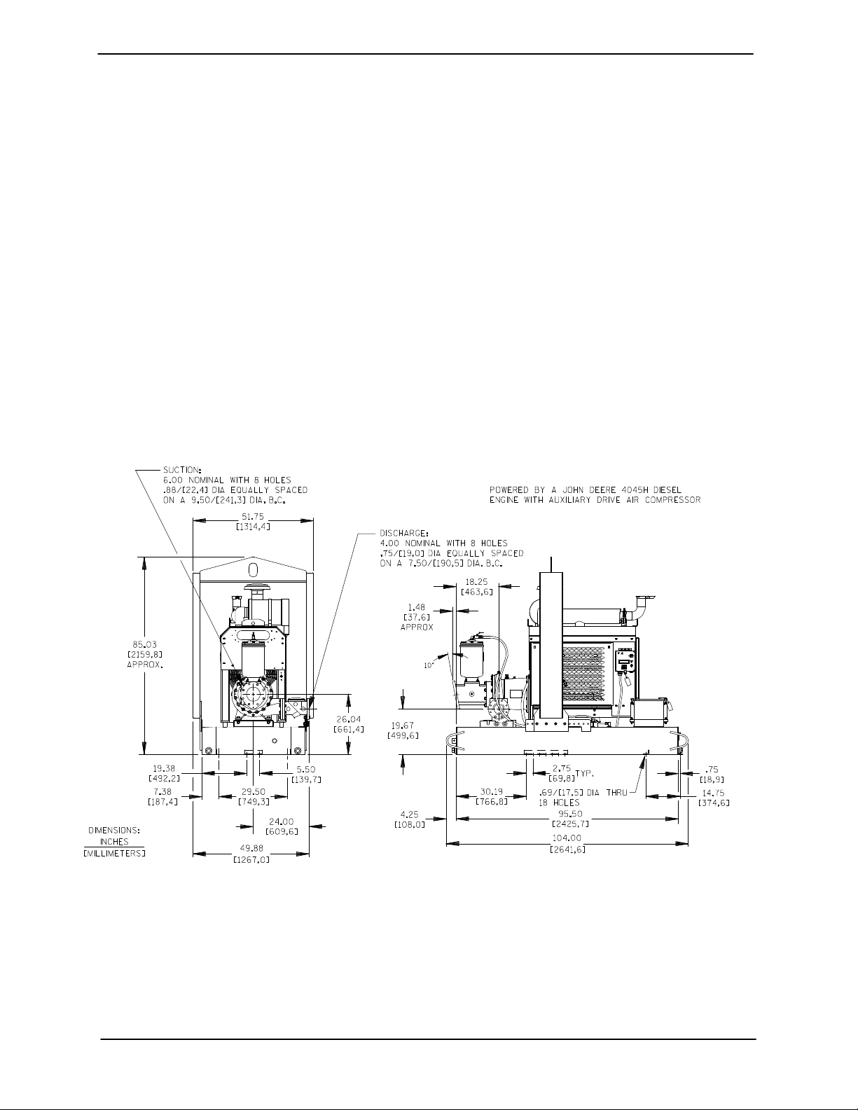
Pump Dimensions
See Figure 1 for the approximate physical dimensions of this pump.
Figure 1. Pump Model PA4B60−4045H
PREINSTALLATION INSPECTION
The pump assembly was inspected and tested before shipment from the factory. Before installation,
inspect the pump for damage which may have occurred during shipment. Check as follows:
a. Inspect the pump for cracks, dents, damaged
threads, and other obvious damage.
b. Check for and tighten loose attaching hard-
ware. Since gaskets tend to shrink after drying, check for loose hardware at mating surfaces.
PAGE B − 1INSTALLATION
Page 10
OM−06228 PA SERIES
c. Carefully read all tags, decals, and markings
on the pump assembly, and perform all duties
indicated. Note that the pump shaft rotates in
the required direction.
d. Check levels and lubricate as necessary. Re-
fer to LUBRICATION in the Maintenance and
Repair Manual and perform duties as instructed.
e. If the pump has been stored for more than 12
months, some of the components or lubricants may have exceeded their maximum
shelf life. These must be inspected or re-
placed to ensure maximum pump service.
If the maximum shelf life has been exceeded, or if
anything appears to be abnormal, contact your
Gorman-Rupp distributor or the factory to determine the repair or updating policy. Do not put the
pump into service until appropriate action has
been taken.
pump. If chains or cable are wrapped
around the pump to lift it, make certain
that they are positioned so as not to
damage the pump, and so that the load
will be balanced. The bail is intended for
use in lifting the pump assembly only.
Suction and discharge hoses and piping must be removed from the pump before lifting.
Lifting
Pump unit weights will vary depending on the
mounting and drive provided. Check the shipping
tag on the unit packaging for the actual weight, and
use lifting equipment with appropriate capacity.
Drain the pump and remove all customer-installed
equipment such as suction and discharge hoses
or piping before attempting to lift existing, installed
units.
Battery Installation
Unless otherwise specified on the pump order, the
engine battery is not included with engine driven
units.
Refer to the information accompanying the battery
and/or electrolyte solution for activation and charging instructions.
Before installing the battery, clean the positive and
negative cable connectors, and the battery terminals. Secure the battery by tightening the
holddown brackets. The terminals and clamps
may be coated with petroleum jelly to retard corrosion. Connect and tighten the positive cable first,
then the negative cable.
POSITIONING PUMP
The pump assembly can be seriously
damaged if the chains or cables used to lift
and move the unit are improperly wrapped
around the pump.
Mounting
Locate the pump in an accessible place as close as
practical to the liquid being pumped. Level mounting is essential for proper operation. The pump
may have to be supported or shimmed to provide
for level operation and eliminate vibration.
For engine driven units, the pump must be posi-
tioned as level as possible to ensure sufficient lubrication and fuel supply to the engine.
If the pump has been mounted on a moveable
base, make certain the base is stationary by setting
the brake and blocking the wheels before attempting to operate the pump.
Use lifting and moving equipment in
good repair and with adequate capacity
to prevent injuries to personnel or damage to equipment. Attach lifting equipment to the lifting device fitted to the
PAGE B − 2 INSTALLATION
If the pump has been mounted on a movable base, do not attempt to operate the
pump unless the unit is level. Be sure
Page 11

PA SERIES OM−06228
the leveling stands are positioned on a
solid surface, and the wheels are
chocked.
SUCTION AND DISCHARGE PIPING
Pump performance is adversely effected by increased suction lift, discharge elevation, and friction losses. See the performance curve and operating range shown on Page E-1 to be sure your
overall application allows pump to operate within
the safe operation range.
Materials
Either pipe or hose maybe used for suction and
discharge lines; however, the materials must be
compatible with the liquid being pumped. If hose is
used in suction lines, it must be the rigid-wall, reinforced type to prevent collapse under suction. Using piping couplings in suction lines is not recommended.
Line Configuration
Keep suction and discharge lines as straight as
possible to minimize friction losses. Make minimum use of elbows and fittings, which substantially increase friction loss. If elbows are necessary,
use the long-radius type to minimize friction loss.
Connections to Pump
pump performance. Seal the gauge threads with
pipe dope to ensure an airtight seal. Follow the
sealant manufacturer’s recommendations when
selecting and applying the pipe dope. The pipe
dope should be compatible with the liquid being
pumped.
SUCTION LINES
To avoid air pockets which could affect pump priming, the suction line must be as short and direct as
possible. When operation involves a suction lift, the
line must always slope upward to the pump from
the source of the liquid being pumped; if the line
slopes down to the pump at any point along the
suction run, air pockets will be created.
Fittings
Suction lines should be the same size as the pump
inlet. If reducers are used in suction lines, they
should be the eccentric type, and should be installed with the flat part of the reducers uppermost
to avoid creating air pockets. Valves are not normally used in suction lines, but if a valve is used,
install it with the stem horizontal to avoid air pockets.
Strainers
Be certain to use the strainer furnished with the
pump; any spherical solids which pass through the
strainer will also pass through the pump itself.
Before tightening a connecting flange, align it exactly with the pump port. Never pull a pipe line into
place by tightening the flange bolts and/or couplings.
Lines near the pump must be independently supported to avoid strain on the pump which could
cause excessive vibration, decreased bearing life,
and increased shaft and seal wear. If hose-type
lines are used, they should have adequate support
to secure them when filled with liquid and under
pressure.
Gauges
The pump is drilled and tapped for installing discharge pressure and vacuum suction gauges. It is
recommended that gauges be installed to monitor
If a strainer not furnished with the pump is installed
by the pump user, make certain that the total area
of the openings in the strainer is at least three or
four times the cross section of the suction line, and
that the openings will not permit passage of solids
larger than the solids handling capability of the
pump.
This pump is designed to handle up to 0.41 inch
(10,4 mm) diameter spherical solids.
Sealing
Since even a slight leak will affect priming, head,
and capacity, especially when operating with a
high suction lift, all connections in the suction line
should be sealed with pipe dope to ensure an airtight seal. Follow the sealant manufacturer’s rec-
PAGE B − 3INSTALLATION
Page 12
OM−06228 PA SERIES
ommendations when selecting and applying the
pipe dope. The pipe dope should be compatible
with the liquid being pumped.
Suction Lines In Sumps
If a single suction line is installed in a sump, it
should be positioned away from the wall of the
sump at a distance equal to 1 1/2 times the diameter of the suction line.
If there is a liquid flow from an open pipe into the
sump, the flow should be kept away from the suction inlet because the inflow will carry air down into
the sump, and air entering the suction line will reduce pump efficiency.
If it is necessary to position inflow close to the suction inlet, install a baffle between the inflow and the
suction inlet at a distance 1-1/2 times the diameter
of the suction pipe. The baffle will allow entrained
air to escape from the liquid before it is drawn into
the suction inlet.
If two suction lines are installed in a single sump,
the flow paths may interact, reducing the efficiency
of one or both pumps. To avoid this, position the
suction inlets so that they are separated by a distance equal to at least 3 times the diameter of the
suction pipe.
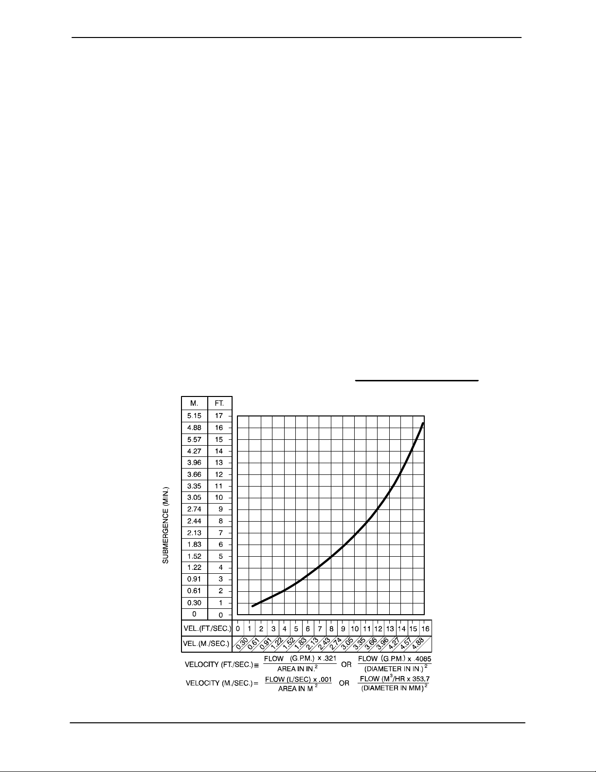
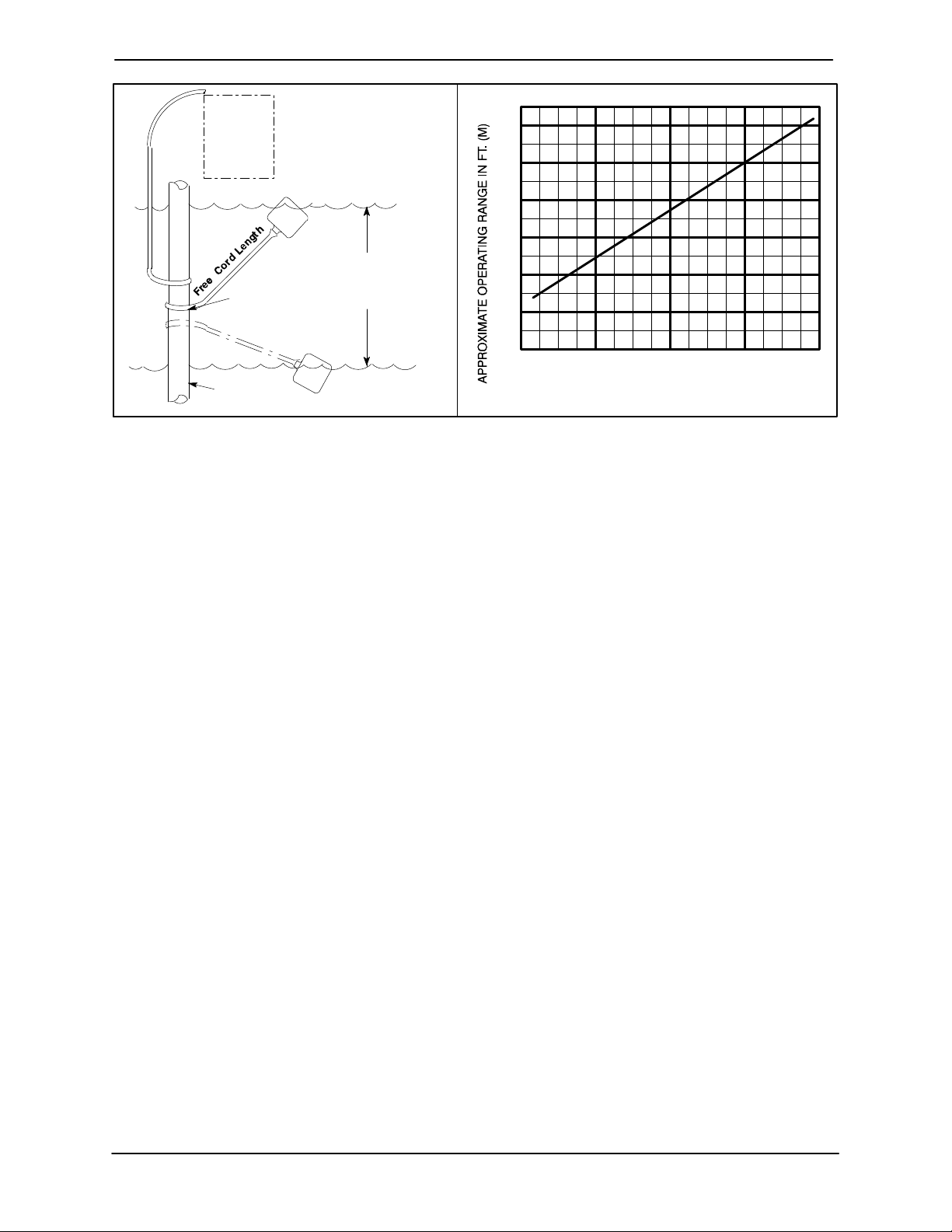
Suction Line Positioning
The depth of submergence of the suction line is
critical to efficient pump operation. Figure 2
shows recommended minimum submergence vs.
velocity.
Although not recommended, the vacuum assisted
priming feature allows the pump to be operated
temporarily in a slurping" application with varying
water levels.
NOTE
The pipe submergence required may be reduced
by installing a standard pipe increaser fitting at the
end of the suction line. The larger opening size will
reduce the inlet velocity. Calculate the required
submergence using the following formula based
on the increased opening size (area or diameter).
Figure 2. Recommended Minimum Suction Line Submergence vs. Velocity
PAGE B − 4 INSTALLATION
Page 13
PA SERIES OM−06228
DISCHARGE LINES
Siphoning
Do not terminate the discharge line at a level lower
than that of the liquid being pumped unless a siphon breaker is used in the line. Otherwise, a siphoning action causing damage to the pump
could result.
Valves
This pump is designed with a check valve in the
discharge line.
If a throttling valve is desired in the discharge line,
use a valve as large as the largest pipe to minimize
friction losses. Never install a throttling valve in a
suction line.
With high discharge heads, it is recommended that
a throttling valve be installed in the discharge line
to protect the pump from excessive shock pressure and reverse rotation when it is stopped.
If the application involves a high discharge
head, gradually close the discharge
throttling valve before stopping the pump.
ALIGNMENT
The alignment of the pump and engine is critical for
trouble-free mechanical operation. See Section E,
Securing Intermediate And Drive Assembly To
Engine in MAINTENANCE AND REPAIR, for de-
tails.
Refer to the information which follows for installation details for the liquid level sensing system provided with your pump.
Float Switch Installation
The Float Switch autostart system employs either a
single or double float switch, where a bulb raises or
lowers (floats) with the liquid level, thus activating
an enclosed miniature switch. The floats are
equipped with a socket type connector that plugs
into a matching receptacle on the auto-start control
box.
Standard floats are equipped with 50 feet (15,2 m)
of cable.
When installing the floats, note the following:
a. Be sure to provide sufficient room in the wet
well or sump so that floats do not get obstructed or drawn into the suction line. If a flexible suction hose is used, it may be extended
to lay along the bottom of the wet well or sump
and the float can be attached to the hose
above the point where it bends along the bottom. Direct the suction line toward the flow,
and the float(s) away from the flow. If a standpipe is available, attach the float switch cable
to the standpipe in the sump at the approximate desired liquid level.
b. In a single float system, the cable can be teth-
ered to the suction line or standpipe approximately 6 inches (152 mm) above the float.
This setting allows approximately 9 inches
(229 mm) of liquid rise between pump start/
stop. The start/stop interval may be increased
by extending the float end of the cable. The
liquid level in the sump will increase approximately 8 inches (203 mm) between start/stop
intervals for every 6 inches (152 mm) of cable
increase.
AUTO-START
The standard pump is equipped with an auto-start
control system which allows the pump to start and
stop as the liquid level in the wet well or sump rises
and falls.
c. If a double float switch system is used, posi-
tion the Start" float at the desired high water
level in the sump, and the Stop" float at the
desired low water level in the pump.
d. Refer to Figure 3 for additional float switch
data.
PAGE B − 5INSTALLATION
Page 14
OM−06228 PA SERIES
ENGINE
CONTROL
BOX
CABLE
TETHER
POINT
1.25" Pipe
(Not Furnished)
ON
(Emptying)
OFF
(Filling)
OPERATING
RANGE
(See Table Below)
OFF
(Emptying)
ON
(Filling)
Figure 3. Float Switch Data
3.0
(0.9)
2.5
(.76)
2.0
(0.6)
1.5
(.46)
1.0
(0.3)
0.5
(.15)
1.0
(0.3)
APPROXIMATE FREE CORD LENGTH IN FT. (M)
2.0
(0.6)
3.0
(0.9)
4.0
(1.2)
PAGE B − 6 INSTALLATION
Page 15
PA SERIES
OM−06228
OPERATION − SECTION C
Review all SAFETY information in Section A.
Follow the instructions on all tags, labels and
decals attached to the pump.
Do not operate an internal combustion
engine in an explosive atmosphere.
When operating an internal combustion
engine in an enclosed area, make sure
exhaust fumes are piped to the outside.
These fumes contain carbon monoxide,
a deadly gas that is colorless, tasteless
and odorless.
OPERATION
cated (see LUBRICATION in MAINTENANCE
AND REPAIR).
The pump will begin to prime upon startup. The air
in the suction line will be discharged from the eductor discharge line. Complete priming is indicated
by a positive discharge pressure reading.
If full priming is not achieved, the discharge check
valve may be malfunctioning. If this occurs, shut
down the pump and consult Maintenance and
Repair, Section E for further details.
STARTING
Check the fuel level and oil levels in the engine, air
compressor, pump bearings and seal housing.
Make sure the pump is level. Lower the jack stands
and chock the wheels, if so equipped.
This pump is designed to handle most
non-volatile, non-flammable liquids
containing specified entrained solids
and corrosives. Do not attempt to pump
volatile, corrosive, or flammable liquids
which may damage the pump or endanger personnel as a result of pump failure.
Pump speed and operating condition
points must be within the continuous performance range shown on the performance curve in Section E on page E−1.
PRIMING
Install the pump and piping as described in INSTALLATION. Make sure that the piping connec-
tions are tight, and that the pump is securely
mounted. Check that the pump is properly lubri-
Make sure the pump is level. Lower jack
stands and chock the wheels, if so
equipped. Use caution when positioning
the skid-mounted unit to prevent damage
to the fuel tank.
This pump is equipped with automatic
liquid level controls, and is subject to
automatic restart. Keep hands and
clothing away from the unit to prevent
injury during automatic operation. Disconnect the positive battery cable before performing any maintenance. Failure to do so may result in serious personal injury.
Consult the engine operations manual before attempting to start the unit.
Manual Starting
On initial start-up, set the engine speed at in the
half-throttle position. Turn the keyswitch to ‘MANU-
OPERATION PAGE C − 1
Page 16

OM−06228 PA SERIES
AL’. After the engine starts and the unit is fully
primed, adjust the engine RPM until the desired
flow rate is achieved.
Pump speed and operating condition
points must be within the continuous performance range shown on the curve on
Page E-1.
Automatic Starting
With the float system installed, follow the procedures outlined for manual starting and throttle adjustment. Switch the keyswitch to ‘OFF’ until the
water level rises above the on point for the float system, then turn the keyswitch to the ‘AUTO’ setting.
The unit will run until the float signals the control
that the water in the wet well is at the float off point,
at which time the unit will shut down automatically.
When the float signals the control that the water in
the wet well is at the float on point, the unit will restart automatically, repeating the cycle.
OPERATION
Leakage
Once the pump is fully primed, no leakage should
be visible at pump mating surfaces, or at pump
connections or fittings. Keep all line connections
and fittings tight to maintain maximum pump efficiency.
Pump Vacuum Check
Read the vacuum gauge with the pump primed
and at operation speed. Shut off the pump. The
vacuum gauge reading will immediately drop proportionate to static suction lift, and should then stabilize. If the vacuum reading falls off rapidly after
stabilization, an air leak exists. Before checking for
the source of the leak, check the point of installation of the vacuum gauge.
Liquid Temperature And Overheating
The maximum liquid temperature for this pump is
160 F (71C). Do not apply it at a higher operating
temperature.
Overheating can occur if operated with the valves
in the suction or discharge lines closed. Operating
against closed valves could bring the liquid to a
boil, build pressure, and cause the pump to rupture or explode. If overheating occurs, stop the
pump immediately and allow it to completely cool
before servicing it. Approach any over-heated
pump cautiously.
Allow an over-heated pump to completely cool before servicing. Do not remove plates, covers, gauges, or fittings
from an overheated pump. Liquid within
the pump can reach boiling temperatures, and vapor pressure within the
pump can cause parts being disengaged to be ejected with great force. After the pump cools, drain the liquid from
the pump by removing the casing drain
plug. Use caution when removing the
plug to prevent injury to personnel from
hot liquid.
As a safeguard against rupture or explosion due to
heat, this pump is equipped with a pressure relief
valve which will open if vapor pressure within the
pump casing reaches a critical point. If over-heating does occur, stop the pump immediately and allow it to cool before servicing it. Approach any
over-heated pump cautiously. It is recommended that the pressure relief valve assembly be
replaced at each overhaul, or any time the pump
casing over-heats and activates the valve. Never
replace this valve with a substitute which has not
been specified or provided by the Gorman-Rupp
Company.
Strainer Check
Check the strainer regularly, and clean it as necessary. The strainer should also be checked if pump
flow rate begins to drop. Monitor and record the
OPERATIONPAGE C − 2
Page 17

PA SERIES
OM−06228
vacuum suction gauge readings regularly to detect
strainer blockage.
Never introduce air or steam pressure into the
pump casing or piping to remove a blockage. This
could result in personal injury or damage to the
equipment. If backflushing is absolutely necessary, liquid pressure must be limited to 50% of the
maximum permissible operating pressure shown
on the pump performance curve.
STOPPING
Never halt the flow of liquid suddenly. If the liquid
being pumped is stopped abruptly, damaging
shock waves can be transmitted to the pump and
piping system. Close all connecting valves slowly.
Reduce the throttle speed slowly and allow the engine to idle briefly before stopping.
normal for bearings, and they can operate safely to
at least 180F (82C).
Checking bearing temperatures by hand is inaccurate. Bearing temperatures can be measured accurately by placing a contact-type thermometer
against the housing. Record this temperature for
future reference.
A sudden increase in bearing temperatures is a
warning that the bearings are at the point of failing
to operate properly. Make certain that the bearing
lubricant is of the proper viscosity and at the correct level (see LUBRICATION in the Maintenance
and Repair Manual). Bearing overheating can also
be caused by shaft misalignment and/or excessive
vibration.
When pumps are first started, the bearings may
seem to run at temperatures above normal. Continued operation should bring the temperatures
down to normal levels.
If the application involves a high discharge
head, gradually close the discharge
throttling valve before stopping the pump.
After stopping the pump, switch off the engine ignition and remove the key to ensure that the pump
will remain inoperative.
BEARING TEMPERATURE CHECK
Bearings normally run at higher than ambient temperatures because of heat generated by friction.
Temperatures up to 160F (71C) are considered
Cold Weather Preservation
In below freezing conditions, drain the pump to
prevent damage from freezing. Also, clean out any
solids by flushing with a hose. Operate the pump
for approximately one minute; this will remove any
remaining liquid that could freeze the pump rotating parts. If the pump will be idle for more than a
few hours, or if it has been pumping liquids containing a large amount of solids, drain the pump,
and flush it thoroughly with clean water. To prevent
large solids from clogging the drain port and preventing the pump from completely draining, insert
a rod or stiff wire in the drain port, and agitate the
liquid during the draining process. Clean out any
remaining solids by flushing with a hose.
OPERATION PAGE C − 3
Page 18

Page 19

PA SERIES
TROUBLESHOOTING − SECTION D
Review all SAFETY information in Section A.
Before attempting to open or service the
pump:
1. Familiarize yourself with this manual.
2. Shut down the engine and disconnect the positive battery cable and
take precautions to ensure that the
pump will remain inoperative.
3. Allow the pump to completely cool if
overheated.
4. Check the temperature and make
sure pump is cool before opening
any covers, plates, or plugs.
5. Close the suction and discharge
valves.
6. Vent the pump slowly and cautiously.
7. Drain the pump.
OM−06228
TROUBLE POSSIBLE CAUSE PROBABLE REMEDY
PUMP FAILS TO
PRIME
PUMP STOPS OR
FAILS TO DELIVER
RATED FLOW OR
PRESSURE
Discharge check valve contaminated, damaged, or unable to seat.
Air compressor head 180 out. Consult factory.
Air leak in suction line. Correct leak.
Lining of suction hose collapsed. Replace suction hose.
Leaking or worn seal or pump gasket. Check pump vacuum. Replace
Suction lift or discharge head too high. Check piping installation and install
Air compressor damaged or belts broken.
Strainer clogged. Check strainer and clean if neces-
Eductor clogged. Check and clean eductor.
Air leak in suction line. Correct leak.
Lining of suction hose collapsed. Replace suction hose.
Leaking or worn seal or pump gasket. Check pump vacuum. Replace
Clean or replace check valve.
leaking or worn seal or gasket.
bypass line if needed. See INSTAL-
LATION.
Check and repair/replace.
sary.
leaking or worn seal or gasket.
TROUBLESHOOTING PAGE D − 1
Page 20

OM−06228
TROUBLE POSSIBLE CAUSE PROBABLE REMEDY
PA SERIES
PUMP STOPS OR
FAILS TO DELIVER
RATED FLOW OR
PRESSURE (cont.)
PUMP REQUIRES
TOO MUCH
POWER
Strainer clogged.
Discharge check valve clogged.
Suction intake not submerged at
proper level or sump too small.
Impeller or other wearing parts worn
or damaged.
Discharge head too high.
Suction lift too high.
Pump speed too slow. Check engine output; consult en-
Belt or flexible coupling broken. Check and replace as necessary.
Pump speed too high. Check engine output.
Extreme ambient temperature. Reduce pump output.
Discharge head too low.
Fuel filter clogged. Check & replace often in extreme
Check strainer and clean if necessary.
Check and clean check valve.
Check installation and correct
submergence as needed.
Replace worn or damaged parts.
Check that impeller is properly
centered and rotates freely.
Free impeller of debris.Impeller clogged.
Install bypass line.
Measure lift w/vacuum gauge. Reduce lift and/or friction losses in
suction line.
gine operation manual.
Adjust discharge valve.
operating conditions.
PUMP CLOGS
FREQUENTLY
EXCESSIVE NOISE
Dilute if possible.Liquid solution too thick.
Check and replace as required.Fuel contaminated.
Pump or jack shaft bearing(s) frozen. Disassemble, check and replace
bearing(s) as required..
Discharge flow too slow.
Suction check valve or foot valve
clogged or binding.
Liquid solution too thick.
Cavitation in pump. Reduce suction lift and/or friction
Pumping entrained air.
Impeller clogged or damaged.
Open discharge valve fully to increase flow rate, and run engine at
maximum governed speed.
Clean valve.
Dilute if possible.
losses in suction line. Record vacuum and pressure gauge readings
and consult local representative or
factory.
Locate and eliminate source of air
bubble.
Secure mounting hardware.Pump or drive not securely mounted.
Clean out debris; replace damaged
parts.
TROUBLESHOOTINGPAGE D − 2
Page 21

PA SERIES
TROUBLE POSSIBLE CAUSE PROBABLE REMEDY
OM−06228
BEARINGS RUN
TOO HOT
Bearing temperature is high, but
within limits.
Low or incorrect lubricant.
Suction and discharge lines not properly supported.
Excessive tension on drive belt.
PREVENTIVE MAINTENANCE
Since pump applications are seldom identical, and
pump wear is directly affected by such things as
the abrasive qualities, pressure and temperature
of the liquid being pumped, this section is intended
only to provide general recommendations and
practices for preventive maintenance. Regardless
of the application however, following a routine preventive maintenance schedule will help assure
trouble-free performance and long life from your
Gorman-Rupp pump. For specific questions concerning your application, contact your GormanRupp distributor or the Gorman-Rupp Company.
Record keeping is an essential component of a
good preventive maintenance program. Changes
in suction and discharge gauge readings (if so
Check bearing temperature regularly to monitor any increase.
Check for proper type and level of
lubricant.
Check piping installation for proper
support.
Align drive properly.Drive misaligned.
Check belt tension. Adjust as
required.
equipped) between regularly scheduled inspections can indicate problems that can be corrected
before system damage or catastrophic failure occurs. The appearance of wearing parts should also
be documented at each inspection for comparison
as well. Also, if records indicate that a certain part
(such as the seal) fails at approximately the same
duty cycle, the part can be checked and replaced
before failure occurs, reducing unscheduled down
time.
For new applications, a first inspection of wearing
parts at 250 hours will give insight into the wear rate
for your particular application. Subsequent inspections should be performed at the intervals shown
on the chart below. Critical applications should be
inspected more frequently.
TROUBLESHOOTING PAGE D − 3
Page 22

OM−06228
PA SERIES
Preventive Maintenance Schedule
Service Interval*
Item
General Condition (Temperature, Unusual
Noises or Vibrations, Cracks, Leaks,
Loose Hardware, Etc.) I
Pump Performance (Gauges, Speed, Flow) I
Bearing Lubrication I
Seal Lubrication (And Packing Adjustment,
If So Equipped) I R
V-Belts (If So Equipped) I
Air Release Valve Plunger Rod (If So Equipped) I C
Front Impeller Clearance (Wear Plate) I
Rear Impeller Clearance (Back Plate) I
Check Valve I
Pressure Relief Valve (If So Equipped) C
Pump and Driver Alignment I
Shaft Deflection I
Bearings I
Bearing Housing I
Piping I
Driver Lubrication − See Mfgr’s Literature
Daily Weekly Monthly Semi-
Annually
Annually
Legend:
I = Inspect, Clean, Adjust, Repair or Replace as Necessary
C = Clean
R = Replace
* Service interval based on an intermittent duty cycle equal to approximately 4000 hours annually.
Adjust schedule as required for lower or higher duty cycles or extreme operating conditions.
TROUBLESHOOTINGPAGE D − 4
Page 23

PA SERIES
OM−06228
PUMP MAINTENANCE AND REPAIR − SECTION E
MAINTENANCE AND REPAIR OF THE WEARING PARTS OF THE PUMP WILL MAINTAIN PEAK
OPERATING PERFORMANCE.
STANDARD PERFORMANCE FOR PUMP MODEL PA4B60−4045H
Based on 70F (21C) clear water at sea level
with minimum suction lift. Since pump installations
are seldom identical, your performance may be different due to such factors as viscosity, specific
gravity, elevation, temperature, and impeller trim.
Contact the Gorman-Rupp Company to verify performance or part numbers.
Pump speed and operating condition
If your pump serial number is followed by an N",
your pump is NOT a standard production model.
MAINTENANCE & REPAIR PAGE E − 1
points must be within the continuous performance range shown on the curve.
Page 24

OM−06228 PA SERIES
PARTS PAGE
SECTION DRAWING
Figure 1. Pump Model PA4B60−4045H
MAINTENANCE & REPAIRPAGE E − 2
Page 25

PA SERIES
OM−06228
PARTS LIST
Pump Model PA4B60−4045H
(From S/N 1417817 Up)
ITEM
NO.
1 PUMP END ASSEMBLY PA4B60−(SAE 4/10) −−− 1
2 POWER UNIT KIT 46143−099 −−− 1
3 BATTERY SEE OPTIONS REF
4 PUMP MOUNTING KIT 48157−036 −−− 1
NOT SHOWN:
PART NAME
PRIME AIRE DECAL 38812−078 −−− 2
G-R DECAL GR−06 −−− 3
INSTRUCTION TAG 38817−085 −−− 1
CAUTION DECAL 2613FJ −−− 1
WARNING DECAL 2613FE −−− 1
PART
NUMBER
MAT’L
CODE
QTY
MAINTENANCE & REPAIR PAGE E − 3
Page 26

OM−06228 PA SERIES
SECTION DRAWING
Figure 2. 46143−088 Power Unit Kit
MAINTENANCE & REPAIRPAGE E − 4
Page 27

PA SERIES
OM−06228
PARTS LIST
46143−088 Power Unit Kit
ITEM
NO.
1 JOHN DEERE ENGINE 29224−309 −−− 1
2 BASE/FUEL TANK 41553−006 24150 1
3 LIFTING BAIL KIT 48274−804 −−− 1
4 MUFFLER GUARD ASSEMBLY NOT REQUIRED −−− 1
5 MALE ELBOW 26351−131 −−− 1
6 CONNECTOR S1447 −−− 2
7 HOSE ASSEMBLY 46341−789 −−− 1
8 BATTERY BOX KIT 42432−005 −−− 1
9 OIL DRAIN ASSEMBLY 46342−013 −−− 1
10 POSITIVE CABLE ASSEMBLY 47311−137 −−− 1
11 FUEL GAUGE 29332−135 −−− 1
12 FUEL PICKUP/RETURN 29332−145 −−− 2
13 HOSE BARB FITTING 26523−386 −−− 2
14 HOSE 11308G −−− 1
15 HOSE CLAMP 26518−641 −−− 2
16 HEX HD CAPSCREW B1007 15991 4
17 HEX NUT D10 15991 4
18 LOCKWASHER J10 15991 4
19 FLAT WASHER K10 15991 4
20 PIPE ELBOW R08 11999 1
21 VENTURI 26817−002 −−− 1
22 1/2" PIPE COUPLING AE08 15079 1
23 BALL/CHECK VALVE 26641−092 −−− 1
24 HOSE BARB FITTING 26523−446 −−− 1
25 REDUCING PIPE BUSHING AP0806 15079 1
26 PIPE UNION AH08 11999 1
27 TEE U08 11999 1
28 MALE ADAPTOR 26351−065 −−− 2
29 HOSE ASSEMBLY 46341−426 −−− 1
30 PRESSURE RELIEF VALVE 26662−028 −−− 1
31 CONNECTOR S1598 −−− 1
32 HOSE BARB FITTING 26523−047 −−− 1
33 1/2" ID x 60" LG. HOSE 18513−113 −−− 1
34 NEG. BATTERY CABLE 47311−133 −−− 1
35 CONTROL PANEL KIT 48122−544 −−− 1
NOT SHOWN:
OPTIONAL:
PART NAME
ENGINE STARTUP TAG 38816−269 −−− 1
WARNING DECAL 38816−203 −−− 4
INSTRUCTION DECAL 38818−144 −−− 1
FLOAT SWITCH KIT 48312−980 −−− 1
WARNING DECAL 38816−132 −−− 2
DUAL FLOAT SWITCH KIT 48312−981 −−− 1
DRY BATTERY 29331−517 −−− 1
WET BATTERY 29331−527 −−− 1
WHEEL KIT GRP30−262 −−− 1
EPS W/TRANSDUCER AUTO CONT PANEL 48122−545 −−− 1
PART
NUMBER
MAT’L
CODE
QTY
MAINTENANCE & REPAIR PAGE E − 5
Page 28

OM−06228 PA SERIES
SECTION DRAWING
Figure 3. PA4B60−(SAE 4/10) Pump End Assembly
MAINTENANCE & REPAIRPAGE E − 6
Page 29

PA SERIES
OM−06228
PARTS LIST
PA4B60−(SAE 4/10) Pump End Assembly
ITEM
NO.
1 PUMP ASSEMBLY 64B60−(SAE 4/10) −−− 1
2 GASKET 1679G 18000 1
3 STUD C1211 15991 8
4 HEX NUT D12 15991 8
5 LOCK WASHER J12 15991 8
6 SUCTION HOPPER SPOOL 38642−507 10000 1
7 DISCHARGE CHECK VALVE ASSY 26642−124 −−− 1
8 GASKET 1676G 18000 1
9 HEX HD CAPSCREW B1010 15991 6
10 HEX NUT D10 15991 6
11 LOCK WASHER J10 15991 6
12 GASKET 1676G 18000 1
13 BLIND FLANGE ASSY 42111−358 −−− 1
14 LOCK WASHER J10 15991 8
15 HEX HD CAPSCREW B1008 15991 8
16 PRIMING HOPPER KIT 48275−006 −−− 1
17 PIPE PLUG P04 15079 2
NOT SHOWN:
OPTIONAL:
PART NAME
−FLAPPER 26685−005 −−− 1
−O-RING 25152−366 −−− 1
DRIVE SCREW BM#04−03 17000 4
NAME PLATE 38818−127 13000 1
STRAINER S1529 24000 1
4" NPT THREADED SUCT FLANGE KIT 48274−203 −−− 1
6" NPT THREADED DISCH FLANGE KIT 48274−205 −−− 1
PART
NUMBER
MAT’L
CODE
QTY
INDICATES PARTS RECOMMENDED FOR STOCK
MAINTENANCE & REPAIR PAGE E − 7
Page 30

OM−06228 PA SERIES
SECTION DRAWING
Figure 4. 64B60−(SAE 4/10) Pump Assembly
MAINTENANCE & REPAIRPAGE E − 8
Page 31

PA SERIES
PARTS LIST
64B60−(SAE 4/10) Pump Assembly
ITEM
PART NAME PART
NO.
1 PUMP CASING 38218−017 10000 1
2 IMPELLER 38628−547 10010 1
3 MECH SEAL ASSY 46512−048 −−− 1
4 PIPE PLUG P06 15079 2
5 CASING GASKET 38684−502 18000 1
6 AIR VENT S1703 −−− 1
7 RED PIPE BUSHING AP1206 15079 1
8 SIGHT GAUGE S1471 −−− 1
9 BEARING ADJ SHIM SET 8548 15990 1
10 LUBE FITTING S194 −−− 1
11 CAP PLUG 25141−151 −−− 1
12 INTERMEDIATE 38264−703 10000 1
13 DRIVE ASSY 44162−119 −−− 1
14 SHAFT KEY N0608 15990 1
15 IMPELLER SHAFT 38515−585 1706H 1
16 PILOT BUSHING 8312A 15010 1
17 GASKET 38683−446 18000 1
18 HEX HD CAPSCREW B0606 15991 3
19 LOCK WASHER J06 15991 3
20 RETAINING RING 24121−080 −−− 1
21 OIL CHAMBER PLATE 31255−009 15080 1
22 O-RING 25152−278 −−− 1
23 BEARING RETAINER 38322−526 10000 1
24 RETAINING RING S720 −−− 1
25 DBL ROLLER BRG 23421−414 −−− 1
26 RETAINING RING S720 −−− 1
27 PIPE PLUG P12 15079 1
NUMBER
MAT’L
CODE
QTY ITEM
NO.
28
28A
29 STUD C1009 15991 4
30 HEX NUT D10 15991 4
31 LOCK WASHER J10 15991 4
32 PIPE PLUG P04 15079 1
33 STUD C1009 15991 16
34 HEX NUT D10 15991 16
35 BALANCE RING 64H6 14000 1
36 WEAR RING 64H5 15000 1
37 IMPELLER WASHER K14 15991 1
38 IMPELLER LOCK NUT BC14S 15991 1
39 HEX HD CAPSCREW B0604 15991 2
40 IMPELLER KEY N0608 15990 1
41 PIPE PLUG P04 15079 1
42 SUCTION STICKER 6588AG −−− 1
43 SUCTION HEAD 38247−418 10000 1
44 SUCTION HEAD GASKET 7557G 18000 1
45 SHAFT SLEEVE 31163−018 17060 1
46 SHAFT SLEEVE O-RING 25154−026 −−− REF
47 SPRING HOLDER 31167−023 15000 1
48 IMP ADJ SHIM SET 5091 17090 1
NOT SHOWN:
OM−06228
PART NAME PART
NUMBER
OIL SEAL 25227−773 −−− 1
OIL SEAL 25227−773 −−− 1
OIL LEVEL DECAK 38816−123 −−− 1
DISCHARGE STICKER 6588BJ −−− 1
INTERMEDIATE GRD ASSY42381−504 −−− 2
MAT’L
CODE
QTY
INDICATES PARTS RECOMMENDED FOR STOCK
MAINTENANCE & REPAIR PAGE E − 9
Page 32

OM−06228 PA SERIES
SECTION DRAWING
Figure 5. 44162−119 Drive Assembly
ITEM
NO.
1 COUPLING KIT 48112−001 −−− 1
2 −BUSHING 24131−345 −−− 1
3 −COUPLING ASSY 44165−011 −−− 1
4 −LOCK WASHER 21171−536 −−− 8
5 −SOCKET HD CAPSCREW BD0606−1/2 15991 8
5 −SOCKET HD CAPSCREW 22644−220 −−− 8
6 HEX HEAD CAPSCREW B0605 15991 12
6 HEX HEAD CAPSCRW 22645−164 −−− 12
7 LOCKWASHER J06 15991 12
7 LOCKWASHER 21171−511 −−− 12
PART NAME
USE FOR SAE APPLICATIONS
USE FOR METRIC APPLICATIONS
PART
NUMBER
MAT’L
CODE
MAINTENANCE & REPAIRPAGE E − 10
QTY
Page 33

PA SERIES
OM−06228
SECTION DRAWING
Figure 6. 48275−006 Priming Chamber Kit
ITEM
NO.
1 BALL VALVE 26631−114 −−− 1
2 STREET ELBOW RS16 11990 1
3 PRIMING CHAMBER ASSY 46112−709 −−− 1
4 HEX NUT D08 15991 4
5 LOCK WASHER J08 15991 4
6 STUD C0809 15991 4
7 BAFFLE 31113−011 17000 1
8 GASKET 38687−053 19060 1
INDICATES PARTS RECOMMENDED FOR STOCK
MAINTENANCE & REPAIR PAGE E − 11
PART NAME
PART
NUMBER
MAT’L
CODE
QTY
Page 34

OM−06228 PA SERIES
SECTION DRAWING
Figure 7. 46112−709 Priming Chamber Assembly
ITEM
NO.
1 PRIMING VALVE 26664−007 −−− 1
2 HEX HD CAPSCREW B0806 15991 8
3 LOCKWASHER J08 15991 8
4 PRIMING VALVE GASKET 38683−657 19060 1
5 PRIMING CHAMBER 38343−020 10000 1
6 STRAINER ASSY 46641−222 17000 1
INDICATES PARTS RECOMMENDED FOR STOCK
PART NAME
−ORIFICE BUTTON 26688−021 −−− 1
PART
NUMBER
MAT’L
CODE
MAINTENANCE & REPAIRPAGE E − 12
QTY
Page 35

OM−06228PA SERIES
PUMP AND SEAL DISASSEMBLY AND REASSEMBLY
Review all SAFETY information in Section A.
Follow the instructions on all tags, label and decals attached to the pump.
This pump requires little service due to its rugged,
minimum-maintenance design. However, if it becomes necessary to inspect or replace the wearing
parts, follow these instructions which are keyed to
the sectional views (see Figures 1 through 7) and
the accompanying parts lists.
This manual will alert personnel to known procedures which require special attention, to those
which could damage equipment, and to those
which could be dangerous to personnel. However,
this manual cannot possibly anticipate and provide
detailed precautions for every situation that might
occur during maintenance of the unit. Therefore, it
is the responsibility of the owner/maintenance personnel to ensure that only safe, established main-
tenance procedures are used, and that any procedures not addressed in this manual are performed
only after establishing that neither personal safety
nor pump integrity are compromised by such practices.
Before attempting to service the pump, switch off
the engine ignition and disconnect the positive battery cable to ensure that the pump will remain inoperative. Close all valves in the suction and discharge lines.
For engine disassembly and repair, consult the literature supplied with the engine, or contact your
local engine representative.
ensure that the pump will remain
inoperative.
3. Allow the pump to completely cool
if overheated.
4. Check the temperature before
opening any covers, plates, or
plugs.
5. Close the suction and discharge
valves.
6. Vent the pump slowly and cautiously.
7. Drain the pump.
This pump may be used to handle materials which could cause illness through
direct exposure or emitted fumes. Wear
adequate protective clothing when
working on the pump or piping.
Use lifting and moving equipment in
good repair and with adequate capacity
to prevent injuries to personnel or damage to equipment. If slings or chains are
used to move the pump or components,
make sure that the load is balanced;
otherwise serious personal injury or
death could result. Suction and discharge hoses and piping must be removed from the pump before lifting.
This pump is equipped with automatic
liquid level controls, and is subject to
automatic restart. Keep hands and
Before attempting to open or service the
pump:
1. Familiarize yourself with this manual.
2. Shut down the engine and disconnect the positive battery cable to
MAINTENANCE & REPAIR PAGE E − 13
clothing away from the unit to prevent
injury during automatic operation. Disconnect the positive battery cable before performing any maintenance. Failure to do so may result in serious personal injury.
Page 36

PA SERIESOM−06228
Priming Chamber Removal And Disassembly
(Figure 6)
Disconnect the air discharge tubing from the priming chamber assembly (3). Support the priming
chamber assembly using a sling and a suitable lifting device. Remove the hardware (4 and 5) and
separate the priming chamber assembly, gasket
(8) and baffle (7) from the suction spool (4, Figure
3).
(Figure 7)
Remove the hardware (2 and 3) securing the priming valve (1) to the priming chamber (5). Carefully
lift the valve components from the priming chamber. Remove the gasket (4) and clean the mating
surfaces.
If the priming valve float is stuck or the strainer (6) is
clogged, it can usually be cleaned without further
disassembly.
The only serviceable part of the priming valve is the
orifice button (not shown). If liquid continues to bypass through the priming chamber after adjusting
the orifice button (see Priming Chamber Reas-
sembly and Installation for adjustment), the button may require replacement. To replace the orifice
button, remove one of the e-clips" from the pivot
pin closest to the orifice button and remove the pivot pin. This will allow the linkage to be raised high
enough to access the orifice button.
Remove the hex nut and lockwasher securing the
orifice button to the linkage bar and unscrew the
orifice button from the linkage bar.
Discharge Check Valve Removal and
Disassembly
(Figure 3)
Remove the discharge piping. Support the discharge check valve assembly (7) using a sling and
a suitable lifting device. Remove the attaching
hardware (9, 10 and 11) and separate the discharge check valve assembly and gasket (8) from
the pump assembly (1).
cover and O-ring. Separate the valve cover and remove the flapper.
Suction Head Removal
(Figure 4)
Remove the suction and discharge piping. Before
attempting to service the pump, remove the pump
casing drain plug (32) and drain the pump. Clean
and reinstall the drain plug.
Remove the nuts (34) and use the jacking screws
(39) to force the suction head (42) out of the pump
casing. Turn the screws evenly to prevent binding.
Remove the suction head gasket (44).
Inspect the wear ring (36) for excessive wear or
scoring. If replacement is required, use a small bit
to drill two holes horizontally, 180 apart, through
the wear ring. Use a chisel or other suitable tool to
complete the cuts through the wear ring. Use cau-
tion not to damage the suction head bore. Remove
the wear ring from the suction head.
Impeller Removal
(Figure 4)
Before attempting to remove the impeller (2), remove the pipe plug (27) and drain the seal cavity.
This will prevent the seal lubricant from spilling as
the impeller is removed.
To remove the impeller, secure the shaft from rotating by reaching through the discharge port and
tightly wedging a soft-metal bar between the vanes
of the impeller.
Remove the impeller nut and washer (37 and 38).
Install two 3/8−16 UNC by 3-inch long capscrews
(not supplied) in the tapped holes in the impeller
and use a suitable puller to remove the impeller
from the shaft. Use caution when removing the impeller; tension on the seal spring will be released
when the impeller is removed. Retain the impeller
key (40). Remove the metal bar from the impeller
vanes.
The flapper and cover O-ring are the only serviceable parts of the check valve. If the flapper requires
replacement, remove the hardware securing the
Remove the impeller adjusting shims (48). For
ease of reassembly, tie and tag the shims or measure and record their thickness.
MAINTENANCE & REPAIRPAGE E − 14
Page 37

OM−06228PA SERIES
Seal Removal and Disassembly
(Figure 4)
Carefully remove the spring holder (47) and seal
spring. Slide the shaft sleeve (45) and rotating portion of the seal assembly off the shaft as a unit.
Apply oil to the sleeve and work it up under the bellows. Slide the rotating portion of the seal off the
sleeve.
Remove the shaft sleeve O-ring (46) from the shaft.
Use a pair of stiff wires with hooked ends to remove
the stationary seat and O-ring from the pump casing bore.
NOTE
An alternate method of removing the stationary portion of the seal is to remove the pump casing as described below and then press the seal components
out of the pump casing from the back side.
If no further disassembly is required, refer to Seal
Reassembly And Installation.
Separating Intermediate and Drive Assembly
From Engine
(Figure 5)
To service the bearing (25) or drive components,
the intermediate must be separated from the engine.
Support the intermediate using a suitable hoist and
sling and remove the hardware (6 and 7) securing
the intermediate to the engine bellhousing. Separate the assemblies by pulling the intermediate
straight away from the engine.
As the assemblies separate, the flexible portion of
the coupling assembly (3) will remain on the shaft.
To remove the coupling from the shaft, unscrew the
two allen head setscrews from the bushing (2).
Screw one of the setscrews into the puller hole on
the circumference of the bushing. As the coupling
and bushing separate, remove the bushing and
slide the coupling off the shaft. Remove the shaft
key (14, figure 4).
It is not necessary to remove the outer ring of the
coupling from the engine flywheel unless the coupling must be replaced. To remove the ring, disengage the hardware (4 and 5) securing it to the flywheel.
Pump Casing Removal
(Figure 4)
Support the pump casing using a suitable hoist
and sling and remove the hardware securing the
casing to the base.
Remove the hardware (30 and 31) securing the
casing to the intermediate (12). Separate the parts
by pulling the casing straight away from the intermediate. Remove any leveling shims from under
the casing feet. Tie and tag the shims for ease of
reassembly. Remove the casing gasket (5).
Inspect the balance ring (35) for excessive wear or
scoring. If replacement is required, use a small bit
to drill two holes horizontally, 180 apart, through
the wear ring. Use a chisel or other suitable tool to
complete the cuts through the wear ring. Use cau-
tion not to damage the pump casing.
Inspect the pilot bushing (16, Figure 4) for excessive wear or scoring. If replacement is required, it
can be easily removed from the engine flywheel by
making a hydraulic ram from a piece of steel bar
stock. Turn the ram to a diameter of 0.983 inch (25
mm).
When performing the following procedure,
grease can be ejected with great force.
Wear safety glasses or goggles to prevent
injury.
Completely pack the bore of the pilot bushing with
grease. Insert the end of the ram into the I.D. of the
bushing. Strike the ram sharply with a hammer,
compressing the grease, and forcing the bushing
out of the flywheel. Use additional grease as required, and continue to strike the ram until the
bushing is completely free.
MAINTENANCE & REPAIR PAGE E − 15
Page 38

PA SERIESOM−06228
Shaft And Bearing Removal And Disassembly
(Figure 4)
When the pump is properly operated and maintained, the shaft and bearing should not require
disassembly. Disassemble the shaft and bearing
only when there is evidence of wear or damage.
Shaft and bearing disassembly in the field
is not recommended. These operations
should be performed only in a properlyequipped shop by qualified personnel.
After removing the drive components from the impeller shaft, remove the hardware (18 and 19) securing the oil chamber plate (21) to the intermediate. Place a block of wood against the impeller end
of the shaft, and tap the shaft (15), bearing (25),
bearing retainer (23) and oil chamber plate out of
the drive end of the intermediate. Be careful not to
damage the shaft.
is strongly recommended that the bearing
be replaced any time the shaft and bearing
are removed.
Clean the intermediate, shaft and all component
parts (except the bearing) with a soft cloth soaked
in cleaning solvent. Inspect the parts for wear or
damage and replace as necessary.
Most cleaning solvents are toxic and
flammable. Use them only in a well ventilated area free from excessive heat,
sparks, and flame. Read and follow all
precautions printed on solvent containers.
Clean the bearing thoroughly in fresh cleaning solvent. Dry the bearing with filtered compressed air
and coat with light oil.
NOTE
There are no provisions for draining the grease
from the intermediate cavity. Place a drip pan under
the intermediate before removing the shaft and
bearing.
Remove the oil chamber plate, gasket (17) and
bearing retainer. Remove the O-ring (22) and, if
necessary, the retaining ring (20) from the oil
chamber plate. Remove the bearing retainer from
the shaft.
Press the oil seals (18 and 18A) from the intermediate bore.
After removing the shaft and bearing, clean and inspect the bearing in place as follows.
To prevent damage during removal from
the shaft, it is recommended that the bearing be cleaned and inspected in place. It
Bearings must be kept free of all dirt and
foreign material. Failure to do so will greatly shorten bearing life. Do not spin dry
bearings. This may scratch the balls or
races and cause premature bearing failure.
Rotate the bearing by hand to check for roughness
or binding and inspect the bearing rollers. If rotation is rough or the rollers are discolored, replace
the bearing.
The bearing tolerances provide a tight press fit
onto the shaft and a snug slip fit into the intermediate. Replace the bearing, shaft, or intermediate if
the proper bearing fit is not achieved.
If bearing replacement is required, use snap ring
pliers to remove the bearing retaining ring (24)
from the shaft. Use an arbor (or hydraulic) press to
remove the bearing from the shaft.
Remove the inboard retaining ring (26) from the
shaft if required.
MAINTENANCE & REPAIRPAGE E − 16
Page 39

OM−06228PA SERIES
Shaft and Bearing Reassembly and Installation
(Figure 4)
Clean and inspect the bearing as indicated in
Shaft and Bearing Removal and Disassembly.
To prevent damage during removal from
the shaft, it is recommended that the bearing be cleaned and inspected in place. It
is strongly recommended that the bearing
be replaced any time the shaft and bearing
are removed.
Inspect the shaft for distortion, nicks or scratches
or thread damage on the impeller end. Dress small
nicks and burrs with a fine file or emery cloth. Replace the shaft if defective.
The bearing may be heated to ease installation. An
induction heater, hot oil bath, electric oven, or hot
plate may be used to heat the bearing. The bearing
should never be heated with a direct flame or directly on a hot plate.
NOTE
If a hot oil bath is used to heat the bearing, both the
oil and the container must be absolutely clean. If
the oil has been previously used, it must be thor-
oughly filtered.
If removed, install the inboard bearing retaining
ring (26) in the groove in the shaft.
Heat the bearing to a uniform temperature no
higher than 250F (120C), and slide the it onto
the shaft until fully seated against the retaining
ring. This should be done quickly, in one continuous motion, to prevent the bearings from cooling
and sticking on the shaft.
Use caution when handling hot bearings to prevent burns.
NOTE
Position the bearing on the shaft as indicated by the
following illustrations.
BALL LOADING
GROOVE POSITIONED
AWAY FROM IMPELLER
LOADING
GROOVE
DIRECTION OF
THRUST
INSTALLATION OF NEW DEPARTURE OR
BCA/FEDERAL MOGAL 5300W SERIES BEARINGS
(OPEN OR ENCLOSED IMPELLERS)
Figure 8. Bearing Installation
After the bearing has been installed and allowed to
cool, check to ensure that it has not moved out of
position in shrinking. If movement has occurred,
use a suitably sized sleeve and a press to reposition the bearing.
If heating the bearing is not practical, use a suitably
sized sleeve and an arbor (or hydraulic) press to install the bearing on the shaft.
BALL LOADING
GROOVE POSITIONED
TOWARD IMPELLER
LOADING
GROOVE
DIRECTION OF
THRUST
INSTALLATION OF MRC/SKF 5300M OR
FAFNIR 5300W SERIES BEARINGS
(OPEN OR ENCLOSED IMPELLERS)
When installing the bearing onto the shaft,
never press or hit against the outer race,
balls, or ball cage. Press only on the inner
race.
MAINTENANCE & REPAIR PAGE E − 17
Page 40

PA SERIESOM−06228
After the bearing is installed on the shaft, pack the
bearing by hand with No. 0 lithium base grease until the bearing rollers are thoroughly lubricated. Secure the bearing on the shaft with the bearing retaining ring (24).
Slide the shaft and assembled bearing into the intermediate bore from the drive end until the bearing seats squarely against the bore shoulder.
When installing the shaft and bearing into
the bearing bore, push against the outer
race. Never hit the balls or ball cage.
If removed, install the retaining ring (20) in the
groove in the oil chamber plate (21). Install a new
O-ring (22) in the groove in the oil chamber plate
and lubricate it with light oil.
Securing Intermediate and Drive Assembly to
Engine
(Figure 5)
Install the shaft key (14, Figure 4) in the shaft keyway. Position the flexible portion of the coupling assembly (3) on the shaft to the dimension shown in
Figure 5.
NOTE
The flexible portion of the coupling must be properly positioned on the shaft. The heads of the capscrews in the center of the coupling must be posi-
tioned toward the pump end of the shaft.
Align the keyway in the bushing (2) with the shaft
key and slide it onto the shaft. Rotate the flexible
portion of the coupling until the tapped holes for
the two setscrews align with those in the bushing,
and install the setscrews.
Install the same thickness of bearing adjusting
shims (9) as previously remove, and position the
bearing retainer (23) against the shims. Install a
new gasket (17) and press the oil chamber plate
into the intermediate until the retaining ring (20) is
fully seated against the bearing retainer. Secure
the oil chamber plate to the intermediate with the
hardware (18 and 19).
NOTE
Impeller shaft endplay should be between .002 and
.010 inch (0,05 to 0,25 mm). To achieve the correct
endplay, add or remove bearing shims (9) as required.
Position the inboard lip seal (18) in the intermediate
bore with the lip positioned as shown in Figure 4
and press it into the intermediate until it is just flush
with the inner machined face of the intermediate
bore.
Position the outboard lip seal (18A) in the intermediate bore with the lip positioned as shown in
Figure 4 and press it into the intermediate until it is
fully seated against the inboard lip seal.
Lubricate the bearing cavity as indicated in LUBRI-
CATION at the end of this section.
Make certain that the flexible portion of the
coupling is mounted as shown in Figure 5.
The end of the shaft must be recessed
aproximately 0.41 inch (10 mm) from the
face of the bushing. This dimension is
critical. If the coupling is not properly positioned on the shaft, the coupling parts may
not fully engage, or a pre-load condition
can cause premature bearing failure.
With the flexible portion of the coupling and the
bushing properly positioned on the shaft, tighten
the two setscrews in an alternating sequence until
the bushing and coupling are fully secured. Torque
the setscrews to 14.6 ft. lbs. (175 in. lbs. or 2 m.
kg.).
If the complete coupling assembly is being replaced, apply ‘Loctite Retaining Compound No.
242’ or equivalent compound to the threads of the
capscrews (5). Secure the outer ring of the coupling to the engine flywheel by installing the hardware (4 and 5) and torquing the capscrews to 45 ft.
lbs. (540 in. lbs. or 6,2 m. kg.).
NOTE
To ease installation, lightly lubricate the rubber portion of the coupling with a non-petroleum based
MAINTENANCE & REPAIRPAGE E − 18
Page 41

OM−06228PA SERIES
lubricant such as vegetable oil or glycerin, or a silicon-based lubricant such as WD40" or equivalent.
Do not use petroleum-based lubricants, or any other substance which may soften or otherwise damage the rubber.
Using a suitable lifting device, position the assembled coupling, intermediate, shaft and bearings so the flexible portion of the coupling seats inside the outer ring attached to the engine flywheel.
Secure the intermediate to the engine bellhousing
with the previously removed hardware (6 and 7).
Pump Casing Installation
(Figure 4)
If the balance ring (35) was removed, position the
replacement ring in the casing bore with the chamfered end toward the bore shoulder. Press the ring
into the casing until it seats squarely against the
casing shoulder.
Seal Reassembly and Installation
(Figures 4 and 9)
Clean the seal cavity and shaft with a cloth soaked
in fresh cleaning solvent.
Most cleaning solvents are toxic and
flammable. Use them only in a well ventilated area free from excessive heat,
sparks, and flame. Read and follow all
precautions printed on solvent containers.
The seal is not normally reused because wear patterns on the finished faces cannot be realigned
during reassembly. This could result in premature
failure. If necessary to reuse an old seal in an emergency, carefully wash all metallic parts in fresh
cleaning solvent and allow to dry thoroughly.
The balance ring must seat squarely in the
suction head; otherwise binding and/or excessive wear will result.
NOTE
The stationary seat and O-ring for the shaft seal assembly may be installed in the pump casing before
the casing is secured to the intermediate (see Seal
Reassembly and Installation). If the stationary
seat is installed, be careful not to damage it on the
shaft threads.
Position the pump casing over the shaft and
against the intermediate. Secure the casing to the
intermediate with the hardware (30 and 31).
Install any leveling shims used under the pump
casing mounting feet and secure the pump casing
to the base with the previously removed mounting
hardware.
Handle the seal parts with extreme care to prevent
damage. Be careful not to contaminate precision
finished faces; even fingerprints on the faces can
shorten seal life. If necessary, clean the faces with a
non-oil based solvent and a clean, lint-free tissue.
Wipe lightly in a concentric pattern to avoid
scratching the faces.
Inspect the seal components for wear, scoring,
grooves, and other damage that might cause leakage. Clean and polish the shaft sleeve, or replace it
if badly worn. If any components are worn, replace
the complete seal; never mix old and new seal
parts.
If a replacement seal is being used, remove it from
the container and inspect the precision finished
faces to ensure that they are free of any foreign
matter.
To ease installation of the seal, lubricate the stationary seat O-ring, bellows and shaft sleeve with
water or a very small amount of oil, and apply a
drop of light lubricating oil on the finished faces.
Assemble the seal as follows, (see Figure 9).
MAINTENANCE & REPAIR PAGE E − 19
Page 42

PA SERIESOM−06228
SPRING
HOLDER
SHAFT
KEY
SHAFT
SLEEVE
IMPELLER
SHAFT
IMPELLER
SHIMS
IMPELLER
BELLOWS
SPRING
RETAINER
STATIONARY
SEAT
SHAFT
SLEEVE
O-RING
ROTATING
ELEMENT
STATIONARY
ELEMENT
O-RINGS
Figure 9. 46512−048 Seal Assembly
This seal is not designed for operation at
temperatures above 160 F (71 C). Do
not use at higher operating temperatures.
Inspect the pump casing and impeller shaft for
burrs or sharp corners and remove any that exist.
With the stationary seat O-ring lubricated and
installed in the stationary seat, press the stationary
seat and element into the pump casing until it seats
squarely against the bore shoulder. Be careful not
to damage the stationary element. A push tube cut
from a length of plastic pipe would aid this installation. The O.D. of the pipe should be approximately
the same diameter as the O.D. of the seal spring.
NOTE
If the pump casing has not been installed, position
the casing over the shaft and against the intermediate, using caution not to damage the seal stationary
seat and element. Secure the casing to the intermediate with the hardware (30 and 31).
Lubricate the shaft sleeve O-ring (46) and slide it
onto the shaft.
Subassemble the rotating element into the retainer
and bellows. Use even pressure to carefully press
this subassembly onto the lubricated sleeve (45)
until the seal face is just flush with the chamfered
end of the sleeve.
Slide the assembled sleeve and rotating portion of
the seal onto the shaft until the seal faces contact.
Continue to push the sleeve through the seal until it
seats squarely against the shaft shoulder.
Install the seal spring and spring holder (47).
Impeller Installation
(Figure 4)
If the balance ring (35) was removed, press the replacement ring into the pump casing as described
in Pump Casing Installation.
The balance ring must seat squarely in the
MAINTENANCE & REPAIRPAGE E − 20
Page 43

OM−06228PA SERIES
suction head; otherwise binding and/or excessive wear will result.
Inspect the impeller and replace it if cracked or
badly worn.
For maximum pump efficiency, the impeller should
CD
B
2
AB
B
+
A
2
be centered within the volute scroll.
To verify the impeller positioning, measure the
pump casing and impeller as shown in Figure 10.
Use these measurements to calculate the required
impeller location (dimension E). Add or remove impeller adjusting shims (48) until dimension E is obtained.
D
2
E
Step 2Step 1 Step 3
C
+
D
2
=
E
−
Figure 10. Centering Impeller Within Volute Scroll
Install the calculated thickness of impeller shims
(48). Install the impeller key (40) and slide the impeller completely onto the shaft.
Secure the shaft from rotating by reaching through
the discharge port and tightly wedging a soft-metal
bar between the vanes of the impeller. Secure the
impeller with the impeller washer and nut (37 and
38).
NOTE
After the impeller has been properly positioned,
check for free rotation. Correct any scraping binding before further reassembly.
Suction Head Installation
(Figure 4)
If removed at disassembly, press the replacement
wear ring (36) into the suction head (42) until it
seats squarely against the bore shoulder.
The wear ring must seat squarely in the
suction head; otherwise binding and/or excessive wear will result.
Install the suction head gasket (44) and secure the
suction head to the pump casing with the nuts (34).
Make sure the jacking screws (39) do not interfere
with the suction head seating.
Discharge Check Valve Assembly And
Installation
(Figure 3)
The flapper and cover O-ring are the only serviceable parts of the check valve. If the flapper requires
replacement, remove the hardware securing the
cover and O-ring. Separate the valve cover and replace the flapper.
Install the valve cover O-ring and secure the cover
with the previously removed hardware.
Support the discharge check valve assembly (7)
using a sling and a suitable lifting device. Use the
MAINTENANCE & REPAIR PAGE E − 21
Page 44

PA SERIESOM−06228
previously removed hardware (9, 10 and 11) to secure the discharge check valve assembly and gasket (8) to the pump assembly (1).
Priming Chamber Assembly And Installation
(Figure 7)
Clean and inspect the components of the priming
valve (1). Inspect the linkage and ensure the orifice
button (not shown) squarely engages the valve
seat. Replace the orifice button if required (see
Priming Chamber Removal and Disassembly
for orifice button removal).
If the orifice button was removed, screw the new
orifice button into the linkage bar until fully seated.
Align the hole in the linkage bar with the holes in the
bracket and reinstall the pivot pin. Secure the pivot
pin with the previously removed e-clip".
Adjust the orifice button seating as necessary by
screwing the orifice button into or out of the linkage
bar. Proper adjustment is achieved when the orifice button fully seats against the orifice before the
linkage bar on the float bottoms against the
threads on the orifice button. When adjustment is
complete, install and tighten the lock washer and
hex nut securing the orifice button.
Install the strainer (6) and priming valve gasket (4).
adjusting shims until the impeller rotates freely
when the pump is fully assembled.
Be sure the pump and intermediate are secure to
the engine and the base.
Install the suction and discharge lines and open all
valves. Make certain that all piping connections are
tight, properly supported and secure.
Be sure the pump and engine have been properly
lubricated, see LUBRICATION.
LUBRICATION
(Figure 4)
Seal Assembly
Check the oil level regularly through the sight
gauge (8) and maintain it at the middle of the
gauge. When lubrication is required, add SAE No.
30 non-detergent oil through the hole for the air
vent (6). Do not over-lubricate..
NOTE
The white reflector in the sight gauge must be positioned horizontally to provide proper drainage.
Lower the float into the priming chamber (5) and
secure the priming valve with the previously removed hardware (1 and 2).
(Figure 6)
Install the baffle (7) and gasket (6) and use a sling
and suitable lifting device to position the priming
chamber assembly on the hopper spool (not
shown). Secure the priming chamber assembly
with the hardware (4 and 5).
Reconnect the suction piping to the hopper spool
and the air discharge tubing to the priming chamber assembly.
Final Pump Assembly
(Figure 4)
Turn the shaft to make sure that the impeller is not
binding or scraping. If it does, check the installation of the wear ring and balance ring, or remove
When lubricating a dry seal cavity, add approximately 6 quarts (5,7 L) of oil. Check the oil level regularly and refill as required.
To ensure lubrication of the seal assembly,
do not allow the oil level to drop below the
line on the sight gauge.
Bearings
The intermediate was fully lubricated when
shipped from the factory. Under normal conditions,
add three shots of No. 0 lithium base grease from a
grease gun through the grease fitting (10) after
each 250 hours of operation or once each month,
whichever comes first. Do not over-lubricate. Overlubrication can cause the bearing to over-heat, resulting in premature bearing failure.
MAINTENANCE & REPAIRPAGE E − 22
Page 45

Observe the area between the shaft and
bearing retainer (23) as grease is added. If
old grease is forced out as new grease is
added, the bearing cavity is full and should
be disassembled and cleaned immediately.
There are no provisions in the bearing cavity to
drain or flush the lubricant. The pump and intermediate must be disassembled to completely clean
and maintain this cavity.
OM−06228PA SERIES
vals, whichever comes first. Change the grease
more frequently if the pump is operated continuously or installed in an environment where variable
hot and cold temperatures are common.
When lubricating a dry (overhauled) intermediate,
fill the cavity through the lubrication fitting with approximately one third pound (0,15 kg) of grease
(approximately one-third full).
For cold weather operation, consult the factory or a
lubricant supplier for the recommended grade of
lubricant.
Engine
Under normal conditions, change the grease after
each 5000 hours of operation, or at 12 month inter-
Consult the manual supplied with the engine or
contact your local engine representative.
MAINTENANCE & REPAIR PAGE E − 23
Page 46

Page 47

For U.S. and International Warranty Information,
Please Visit www.grpumps.com/warranty
or call:
U.S.: 419−755−1280
International: +1−419−755−1352
For Canadian Warranty Information,
Please Visit www.grcanada.com/warranty
or call:
519−631−2870
THE GORMAN-RUPP COMPANY MANSFIELD, OHIO
GORMAN-RUPP OF CANADA LIMITED ST. THOMAS, ONTARIO, CANADA
 Loading...