

GORMAN-RUPP PUMPS GMS Series Installation, Operation And Maintenance Manual
TVXY
OM-04910
August 12, 1998
Rev. B 01/25/00
INSTALLATION, OPERATION,
AND MAINTENANCE MANUAL
ROTARY GEAR PUMPS
MODELS
GMSSERIESPUMPS
S&TSIZES
THE GORMAN-RUPP COMPANY D MANSFIELD, OHIO
GORMAN-RUPP OF CANADA LIMITED D ST.THOMAS, ONTARIO, CANADA Printed in U.S.A.
ECopyright by the Gorman-Rupp Company


TABLE OF CONTENTS
INTRODUCTION PAGE I --- 1...................................................
SA FE T Y --- SE CT I ON A PA G E A --- 1............................................
IN STA L LAT ION --- SE CTI ON B PA G E B --- 1.....................................
PUMP MODEL DESIGNATION PAGE B---1..................................................
PREINSTALLATION INSPECTION PAGE B---2................................................
STORAGE PA GE B --- 2....................................................................
Flushing PA GE B --- 2..................................................................
PUMP INSTALLATION P AGE B---3..........................................................
Lifting PA GE B --- 3.....................................................................
Positioning The Pump PA GE B --- 3......................................................
Mounting PA GE B --- 3.................................................................
Piping PA GE B --- 3....................................................................
Strainers PA GE B --- 4..................................................................
Gauges PA GE B --- 4...................................................................
Sealing PA GE B --- 4...................................................................
Valves PAGE B --- 4....................................................................
ALIGNMENT PAGE B --- 4..................................................................
Coupled Drives PA GE B --- 4............................................................
V-Belt Drives PA GE B --- 5...............................................................
V-BELT TENSIONING PAGE B---5..........................................................
General Rules of Tensioning PAGE B---5.................................................
Tension Measurement PAGE B---6......................................................
OPER AT IO N --- SE CT I ON C PA G E C --- 1.......................................
PU MP OPERATION PA GE C --- 1............................................................
PRE-OPERATION PAGE C---1..............................................................
Before Starting The Pump PAGE C---1...................................................
Checking Pump Rotation PAGE C---1...................................................
STARTING PA GE C --- 2....................................................................
OPERATION PAGE C --- 2..................................................................
Liquid Temperature PA GE C --- 2.........................................................
Overheating PA GE C --- 2...............................................................
Checking Gauges PAGE C---2..........................................................
Strainer Check PAGE C---3.............................................................
Leakage PAGE C --- 3..................................................................
PRESSURE RELIEF VALVE ADJUSTMENT PAGE C---3........................................
Cracking Pressure PAGE C---3.........................................................
Complete By-Pass Pressure PAGE C---3.................................................
STOPPING PA GE C --- 3....................................................................
TR OUB LES HOO TI NG --- S E CT ION D PA G E D --- 1...............................
TROUBLESHOOTING WITH GAUGES P AGE D---1............................................
TROUBLESHOOTING CHART P AGE D---2...................................................
PREVENTIVE MAINTENANCE PAGE D---4...................................................
PUMP MAINTENANCE AND REPAIR --- SECTION E PAGE E --- 1.................
PARTS KEY:
TypicalGMSS&TSizePumpModel PAGEE---3.........................................
i

TABLE OF CONTENTS
(continued)
ASSEMBLED GMS S & T SIZE PUMP MODEL ILLUSTRATION PAGE E---4......................
PU MP DISASSEMBLY PA GE E --- 5..........................................................
Preparing for Disassembly PA GE E---5..................................................
Pressure Relief Valve (10) PAGE E---6...................................................
Foot Bracket Kit - S Size Only (08) PAGE E---6...........................................
Coverplate Kit (11) PAGE E---6.........................................................
Head/Idler Kit (01/02) PAGE E---6.......................................................
Seal Gland Removal (06I) PAGE E---7...................................................
Rotor/Shaft Removal (03) PAGE E---7...................................................
Backhead Assembly (06) PAGE E---7...................................................
PUMP REASSEMBLY PAGE E---7..........................................................
Cleaning and Inspection PAGE E---7....................................................
Bushing Preparation PAGE E---8........................................................
Backhead Kit (06) PAGE E---8..........................................................
Rotor/Shaft Assembly (03) PAGE E---8..................................................
Head/Idler Kit (01/02) PAGE E---8.......................................................
Coverplate Kit (11) PAGE E---9.........................................................
Seal Gland Installation (06I) PAGE E---9.................................................
Foot Bracket Kit - S Size Only (06I) P AGE E- --9..........................................
SETTING END CLEARANCE PAGE E---9....................................................
RELIEF VALVE DISASSEMBLY (S Hydraulic Size Only) PAGE E---10............................
RELIEF VALVE REASSEMBLY (S Hydraulic Size Only) PAGE E---11.............................
RELIEF VALVE DISASSEMBLY (T Hydraulic Size Only) PAGE E---12............................
RELIEF VALVE REASSEMBLY (T Hydraulic Size Only) PAGE E---13.............................
RELIEF VALVE INSTALLATION PAGE E---13.................................................
SEAL APPENDIX --- SECTION F P AGE F---1...................................
Standard Friction Drive And Option 61M Mechanical Seals PAGE F---1...........................
Option 60N Positive Drive Seal PAGE F---3...................................................
Standard 65 And Option 65Q Packing Seals PAGE F---5.......................................
ii

INTRODUCTION
OM--04910GMS SERIES
Thank You for purchasing a Gorman-RuppRotary
Gear Pump. This manual is designed to help you
achievethebest performanceand longest lifefrom
your Gorman-Rupp Rotary Gear pump. Read this
manual carefully to learn how to safely install, operate and repair your pump. Failure to do so could
result in personal injury or damage to the pump.
This manual will alert personnel to known procedures which require special attention, to those
which could damage equipment, and to those
whichcould be dangerous to personnel. However,
this manual cannot possibly provide detailed instructions and precautions for each specific application or for every situation that might occur during maintenance of the unit. Therefore, it is the responsibility of the owner, installer and/or maintenance personnel to ensure that applications and/
or maintenance procedures not addressed in this
manual are performed only
neither personal safety nor pump integrity are
compromisedbysuchapplicationsorprocedures.
after establishing t hat
If there a re any questions regarding the pump or
drive unit which are not covered in this manual or
in other literature accompanying this unit, please
contact your Gorman-Rupp distributor or the Gorman-Rupp Company:
The Gorman-Rupp Company
P.O. Box 1217
Mansfield, Ohio 44901-- 1217
or:
Gorman-Rupp of Canada Limited
70 Burwell Road
St. Thomas, Ontario N5P 3R7
RECORDING MODEL AND
SERIAL NUMBERS
Please record the pump modeland serial number
in the spaces provided below. Your Gorman-Rupp
distributorneeds thisinformationw hen yourequire
parts or service.
In addition to this manual, a separate Parts List is
shippedwiththepump.RefertothePartsListwhen
ordering parts.
If your pump is furnished with a drive unit, refer to
the drive unit manufacturer’ s installationand operation instructions in the literature accompanying
the pump.
These pumps can transfer a wide range of light,
medium, a nd heavy viscosity liquids, depending
on design and components. Some models are
not recommended for use with water; others
when fitted with specific options, may be used
with water; consult the factory.
Pump Model:
Serial Number:
WARRANTY INFORMATION
The warranty provided with your pump is part of
Gorman-Rupp’s support program for customers
who operate and maintain their equipment as described in this and the other accompanying literature. Please note that should the equipment be
abused or modified to change its performance beyond the original factory specifications, the warranty will become void and any claim will be denied.
INTRODUCTION
PAGE I -- 1
GMS SERIESOM--04910
The following are used to alert personnel to procedures which require special attention, to those which
could damage equipment, and to those which could be dangerous to personnel:
Immediate hazards which will result in
severe personal injury or death. These
instructions describe the procedure required and the injury which will result
from failure to follow the procedure.
Hazards or unsafe practices which
COULDresult in severe personal injury
or death. These instructions describe
the procedure required and the injury
which could result fromfailure to follow
the procedure.
HazardsorunsafepracticeswhichCOULD
resultinminorpersonalinjuryorproductor
property damage. These instructions describe the requirements and the possible
damage which could result from failure to
follow the procedure.
NOTE
Instructions to aid in installation, operation, and
maintenance or which clarify a procedure.
PAGE I -- 2
INTRODUCTION
GMS SERIES OM--04910
SAFETY --- SECTION A
This information is specific to Gorman-Rupp GMS
Series Rotary Gear Pumps.It appliesthroughout
this manual and any manual or literature accompanying the pump.
In addition to this manual, see the separate literature covering the drive unit used to operate this
pump.
Pumps and relatedequipmentmust be installed and operated according to all national, local and industry standards.
This manual will alert personnel to
known procedures which require special attention, to those which could
damage equipment, and to thosewhich
could be dangerousto personnel. However, this manual cannot possibly provide detailed instructions and precautionsfor each specificapplication or for
every situation that might occur during
maintenance of the unit. Therefore, it is
the responsibility of the owner, installer
and/or maintenance personnel to ensure that applications and/or maintenanceproceduresnot addressedin this
manual are performed only after establishing that neither personal safety nor
pump integrity are compromised by
such applications or procedures.
coveredin thismanualcouldleadto destruction of equipment, injury, or death.
The standard versionofthis pump isdesigned to handle a wide range of light,
medium, and heavy viscosity liquid, depending on design and components,
and a range oftemperatures when fitted
with different seals. Do not apply at
higher temperatures than the seal will
handle. Do not attempt to pump liquids
which may damage the pump or endanger personnel as a result of pump failure; consult the factory for chemical
compatibility.
If the pump and motor are furnished
mountedon abase,make certainthat all
lifting devices have adequate capacity.
If chains or cables are used in lifting,
makecertain that they are positioned so
as not to damage components, and so
that the load will be balanced.
Afterthe pump hasbeen installed,make
certain that the pump and all piping or
hoseconnec t ionsare sec ure beforeoperation.Looseconnectionscan resultin
damage to the equipment and serious
injury to personnel.
Before attempting to install, operate, or
service this pump, familiarize yourself
withthismanual,and withall otherliterature shipped with the pump. Unfamiliarity with all aspects ofpumpoperation
SAFETY
Neveroperatethe pump without a pressure relief valve installed on the pump
orin the discharge piping. Make certain
that pump-mounted pressure relief
PAGE A -- 1
OM--04910 GMS SERIES
valves are installed with their adjusting
ends toward the suction port.Ifbi-rotational operation is required, a pressure
relief device must be provided for both
directions of flow. Operation without a
pressure relief valve or with an improperly installed relief valve could cause
the pump to explode, resulting in serious injury or death to personnel.
Beforeattempting toopenorservic e the
pump:
1. Familiarize yourself with this manual.
2. Lock out incoming power to the
drive unit to ensure that the pump
will remain inoperative.
3. Allow the pump tocompletelycool
if overheated.
4. Close the discharge and suction
valve (if used).
3. Refer to the instructions in this
manual before restarting the
pump.
Do not remove plates, covers, gauges,
pipe plugs or fittings from an overheated pump. Vaporpressure within the
pump can cause parts being disengagedto be ejected withgreatforce.Allowthe pump to completely coolbefore
servicing.
Do not operate this pump without
guards in place over the rotating parts.
Exposed rotating parts can catch clothing, fingers or tools, causing severe injury to personnel.
An overheated pump can cause severe
burns and injury.If overheating occurs:
1. Stop the pump immediately.
2. Allowthepumptocompletelycool.
This pump may be used to handle liquidswhichmay cause serious illne ss or
injury through direct exposure or
emitted fumes. Wear protective clothing, such as rubber gloves, face mask
and rubber apron, as necessary, before
disconnecting or servicing the pump or
piping.
PAGE A -- 2
SAFETY
GMS SERIES
OM--04910
INSTALLATION --- SECTION B
Review all SAFETY information in Section A.
Pumps and relatedequipmentmust be installed and operated according to all national, local and industry standards.
Since pump installations areseldom identical,this
sectionis intended only to summarize generalrecommendations and practices required to inspect,
position,and arrangethepump andpiping.Ifthere
are any questions concerning your specific installation, contact your Gorman-Rupp distributor or
the Gorman-Rupp Company.
Mostof theinformation applies toa floodedsuction
installation where liquid is supplied under pressure.
Typical Pump Model
GHS 1 1/2 GF 32
Design
Style
Design Style: Gorman-Rupp rotary gear pumps
are available in five basic designs:
S GMC --- Medium Duty --- Compact
S GMS --- Medium Duty
S GHC --- Heavy Duty --- Compact
S GHS --- Heavy Duty
S GHA --- Abrasive Duty
Port Size: Gorman-Rupp rotary gear pumps are
available in port sizes from 1 to 6 inches, depending on the design style. Consult your GormanRupp distributoror the factory for additional sizes.
Port
Size
Hydraulic
Size
Construction
Code
Ifthepumpis positioned above the liquidin astatic
lift installation, information such as mounting, piping configuration and priming must be tailored to
specific conditions.
Thesepumpsarenotrecommendedfor
use with water. Some models, when fitted
withspecificoptions,maybeusedwithwater; consult the factory.
PUMP MODEL DESIGNATION
Following is a description of the modelnumbering
system for Gorman-Rupp rotary gear pumps.
Rotary gear pump model numbers includedesign
style, port size, hydraulic size and construction
code.
Hydraulic Size: The first letterin the hydraulicsize
is a rotor diameter code. The second letter indicates tooth length.
Construction Code: Construction Codes for Gorman-Rupp rotary gear pumps are as follows:
Code Description
3 Iron w/Mechanical Seal(s)
4Ironw/PackingorLipSeal(s)
9 316 SST w/ M echanical Seal(s)
10 316 SST w/Packing or Lip Seal(s)
32 Steel w/Mechanical Seal(s)
38 Steel w/Packing or Lip Seal(s)
Theoretical Displacement: Table B-1 indicates
theoreticaldisplacement values for each hydraulic
size.
NOTE
Actual capacities and recommended shaft speeds
vary according to application. Consult your Gorman-Rupp distributor or the factory for additional
information.
INSTALLATION
PAGE B -- 1
GMS SERIESOM--04910
Table B-1. Theoretical Displacement
Theoretical Displacement
Hydraulic
Size
DC 0.00568 21.486
DE 0.00704 26.646
GC 0.00967 36.619
GF 0.01405 53.186
GH 0.01915 72.479
GJ 0.02317 87.700
JG 0.03579 135.49
JJ 0.05159 195.28
JL 0.07078 267.94
JP 0.10078 381.48
NK 0.10665 403.71
NM 0.14173 536.51
NP 0.17681 669.31
RM 0.24030 909.65
RP 0.29979 1134.8
RR 0.35927 1360.0
RS 0.41876 1585.1
SR 0.65752 2489.0
SU 1.10240 4173.2
TU 1.91280 7240.7
Per Revolution
Gallons Centimeters
Ifthe pump willnot beimmediately installed, follow
these procedures or damage t o the pump will occur.
a. Do not flush the pump. Ensure that the port
3
plugs shipped with the pump remain in place
until piping is installedto help prevent dust or
other foreignobjects from entering the pump.
b. Pumps that will not be installed for an ex-
tended period should be stored indoors if
possible. The factory-installed port plugs will
not ensure protection from excessive humidity, splash w ater or rain. In very humid or wet
conditions, install air-tight plugs in the ports
andfillthepump completelywith a lubricating
preservative liquid that is compatible with the
liquid to be pumped.
c. Pumps stored outdoors must be fully pre-
servedasdescribedabove, completelycovered with plastic or other water-tightmaterial,
and the covering anchored to ensure that it
will not be blown off.
PREINSTALLATION INSPECTION
Thepump assembly wasinspected and tested before shipment from the factory. Before installation,
check for damage which may have occurred during shipment. Check as follows:
a. Inspectthe pumpassemblyfor cracks, dents,
damaged threads, and other obvious damage.
b. Check for loose attaching hardware. Since
gaskets tend to shrink after drying, check for
loosehardwareatthematingsurfaces.
c. Carefully read all tags, decals, and markings
onthepump assembly,and performallduties
indicated.
STORAGE
Flushing
Cleanpiping is essentialbecauseofclosetolerancemoving partsinthis pump.Flush
all dirt, grit, weld beads or scale from the
suction piping before installing the pump.
Damage to the pump because of debris in
thesuctionlineisnotcoveredbythepump
warranty.
The pump may have been tested using a petroleum-based preservative, or a preservative may
havebeenused for long-term storage of thepump.
Ifflushing is required, do not do so untiljust before
installation; the test oil protects close-tolerance
pump parts from corrosion.
Due to the extreme close machining tolerances within rotary gear pumps, proper
storage before installation is essential to
prevent damage to the pump.
PAGE B -- 2
Most cleaning solvents are toxic and
flammable. Use themonly in a wellventilated area free from flame, sparks, and
excessiveheat. Read and followallprecautions printed on solvent containers.
INSTALLATION
GMS SERIES
OM--04910
To flush the pump, use an approved solvent compatible with the liquid being pumped. Make cer-
tain that the solvent will not attack pump components, particularly seals and gaskets.
PUMP INSTALLATION
Pump dimensions are shown in the separate
Pump Specification Bulletin.
Neveroperatethe pump without a pressure relief valve installed on the pump
orin the discharge piping. Make certain
that pump-mounted pressure relief
valves are installed with their adjusting
ends toward the suction port.Ifbi-rotational operation is required, a pressure
relief device must be provided for both
directions of flow. Operation without a
pressure relief valve or with an improperly installed relief valve could cause
the pump to explode, resulting in serious injury or death to personnel.
Lifting
heavy enough to absorb any vibration, strain or
shock.
Piping
Before establishing suction and discharge lines,
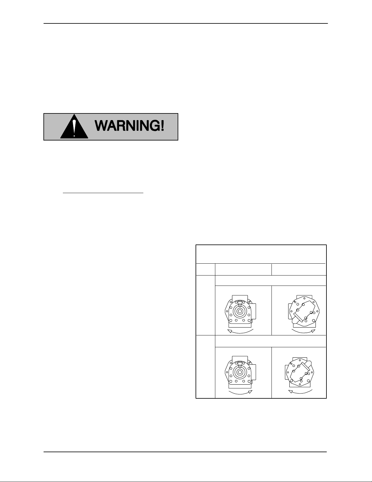
determine pump port positions and rotation. Figure B-1 shows typical port positions for the standard 90_ housing; if you have selected a 180_
housing port option, your port positionswill bedifferent.
Eitherhoseor rigid pipe maybe used to makeconnections. If rigid piping is used, install expansion
joints to protect t he pump from vibration and thermal expansion in the piping. Donot useexpansion
joints or flexible connectors to adjust misaligned
piping.
Begin piping layout at the pump, and work toward
the source of s upply and the point of discharge. If
an obstacle is in the way of a suction or discharge
line, run the piping around the obstruction, not
over it. Running piping over an obstruction will
create anair pocket which willmake primingmore
difficult.
Housing Position Std. 90_ Pump
(3---12 O’clock) Head Mounted Relief Valve
OPT.
Drive End
Front End
Remove suction and discharge hose and piping
beforeattemptingto liftthepump.Useliftingequipment with a capacity of at least five times the total
weight of the equipment being lifted.
Positioning The Pump
Locatethe pump as closeas possible to the liquid
being pumped. Locating the pump below the liquid source will help self-priming and reduce the
possibility of cavitation.
Mounting
The pump may be shipped alone, mounted on a
base,or w ith pumpand motormountedona base.
Install the pump and motor on a base before
mounting the base on a foundation.
Mount the base on a foundation that will provide
permanent, rigid support for the pump, and willbe
Rotation Clockwise
D
STD.
Rotation Counter-clockwise
S
01A
Figure B-1. Typical Port Positions & Rotation
Ifpossible,slopethe pipingtoward thepumpsono
air or liquid is trapped in the piping. If a long horizontal suction line is necessary, install the line below the liquid level whenever possible in order to
S
D
S
D
D
S
INSTALLATION
PAGE B -- 3
GMS SERIESOM--04910
keep the piping fullof liquid. This will make priming
easier because the pump will not have to remove
as much air in the line.
The discharge and suction lines must be independently supported to avoid vibration and strain
on the pump. For maximum pumping capacity,
keepthe lines as shortand straightas possible.Elbows and fittings used in the lines increase friction
losses; minimize their use. Reducers used in suction lines should be the eccentric type installed
with the flat part uppermost to avoid creating air
pockets.
Before tightening a connection or flange, align it
exactly w ith the pump port. Never pull a pipe line
into place by tightening the flange bolts and/or
couplings.
Strainers
Valves
To avoid air pockets, install piping valves with the
stem horizontal.
Topreventleakageduringshutdown, installa shutoff valve in the discharge line, particularly on a
floodedsuction application. Shutoff valves are not
recommended for suction lines.
Itisnot recommended thata foot valve beinstalled
at the end of the suction line. If desired to install a
foot valve, consult the factory.
When handling very hot or cold liquids, install a
pressure relief valve in any part of the system that
can bevalvedoff orisolated; this will protect piping
against damage from liquid thermal expansion or
contraction from temperature changes during
shutdown.
ALIGNMENT
Because of the close-tolerance moving parts of
thispump, it is recommended that a strainer be in stalled in the suction line. The strainer should be
large enough to prevent excessive vacuum, and
capable of operating under high vacuum without
collapsing. The net open area of the strainer
screen depends on liquid viscosity and desired
flowrate; inany case, the sum of the area of all the
holesinthescreenshouldbe three tofivetimesthe
area of the suction pipe.
Gauges
Tomonitoroperationandassistin troubleshooting,
a vacuum gauge and a pressure gauge shouldbe
installed on the pump.
Sealing
Make certain that power to the driveunit
is disconnecte d before attempting to
connectthep ump driv e;otherwise,personal injury may result.
NOTE
See ROTATION in Section C before mounting the
pump on the base.
Coupled Drives
When using couplings, the axis of the power
source must be aligned to the axis of the pump
shaft in both the horizontal and vertical planes.
Mostcouplingsrequire a specific gap or clearance
between the driving and the driven shafts. Refer to
the coupling manufacturer’s service literature.
Even a slight leak will affect priming, head, and capacity, especially in a suction lift application. Seal
all piping joints, valves and gauges with pipe dope
orteflontape. The sealingmaterialshould be compatible with the liquid being pumped.
PAGE B -- 4
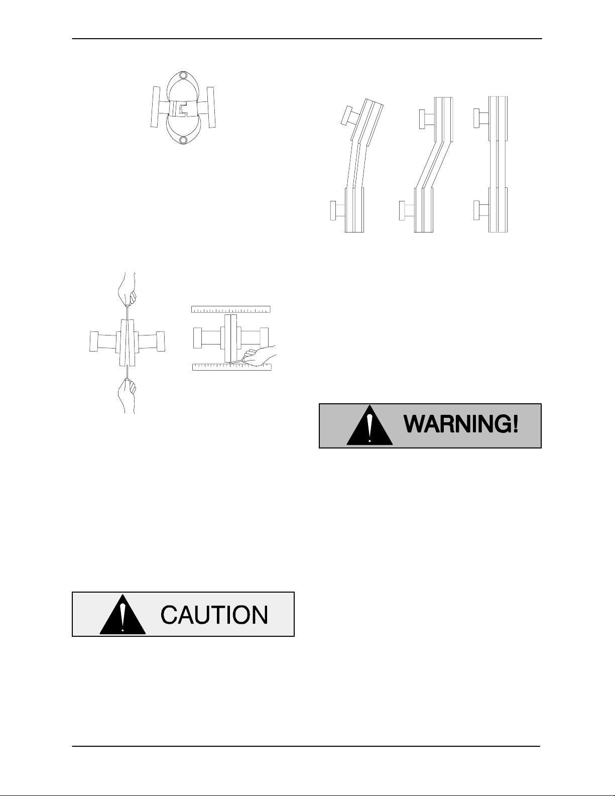
Alignspiderinserttypecouplingsbyusingcalipers
to measure the dimensions on the circumference
of the outer ends of the coupling hub every 90_.
The coupling is in alignment when the hub ends
are the same distance apart at all points (see Figure B-2).
INSTALLATION
GMS SERIES
ARA
A
V
Figure B-2. Spider-type Couplings
Align non-spider type couplings by using a feeler
gaugeortapergaugebetweenthecouplinghalves
every 90_. The coupling is in alignment when the
hubs are the same distanceapart at allpoints (see
Figure B-3).
OM--04910
beltsareamatchedset; unmatched setswillcause
accelerated belt wear.
MISALIGNED:
SHAFTS
NOT P
LLEL
MISALIGNED:
SHAFTS
NOT IN LINE
ALIGNED:SHAFTS
PARALLEL AND
SHE
ES IN LINE
Figure B-4. V- belt Alignment
Tighten the belts in accordance with the belt manufacturer’s instructions. If the belts are too loose
they will slip; if they are too tight, there will be excessive power loss and possible bearing failure.
Figure B-3. Aligning Non-Spider Type Coupling
Checkparalleladjustmentbylayingastraightedge
across both coupling rims at the top, bottom, and
side. When the straightedge rests evenly on both
halves of the coupling, the couplingis in horizontal
parallel alignment. If the coupling is misaligned,
use a feeler gauge between the coupling and the
straightedge to measure the amount of misalignment.
V-Belt Drives
GMS style pumps will require an external
bearing support when using V-belt drives.
Select pulleys to match the proper speed ratio;
overspeeding the pump may damage both pump
and power source.
Do not operate this pump without
guards in place over the rotating parts.
Exposed rotating parts can catch clothing, fingers or tools, causing severe injury to personnel.
V-BELT TENSIONING
General Rules of Tensioning
For new v-belts, check the tension after 5, 20 and
50 hours of operation and re-tension as required
(see the following procedure for measuring belt
tension). Thereafter, check a nd re-tension if required monthlyor at 500 hour intervals, whichever
comes first.
When using V-belt drives, the power source and
the pump must be parallel. Use a straightedge
along the sides of the pulleys to ensure that they
are properly aligned (see Figure B-4). In drive systemsusingtwoormorebelts,make certainthatthe
INSTALLATION
Ideal v-belt tension is the lowest tension at which
the belt willnot slip under peak load conditions.Do
notover-tensionv-belts.Over-tensioningwill shorten both v-belt and bearing life. Under-tensioning
will cause belt slippage. Always keep belts free
PAGE B -- 5
GMS SERIESOM--04910
from dirt, grease, oil and other foreign material
which may cause slippage.
Tension Measurement
Correct v-belt tension can be achieved using a vbelt tension tester and Table B-2 or B-3. Use the
tables to find the v-belt size (cross-section), the
smallestsheavediameter,the belttypeforyourapplication. The corresponding deflection force requiredfor new orused belts is shown opposite the
RPM range of the pump.
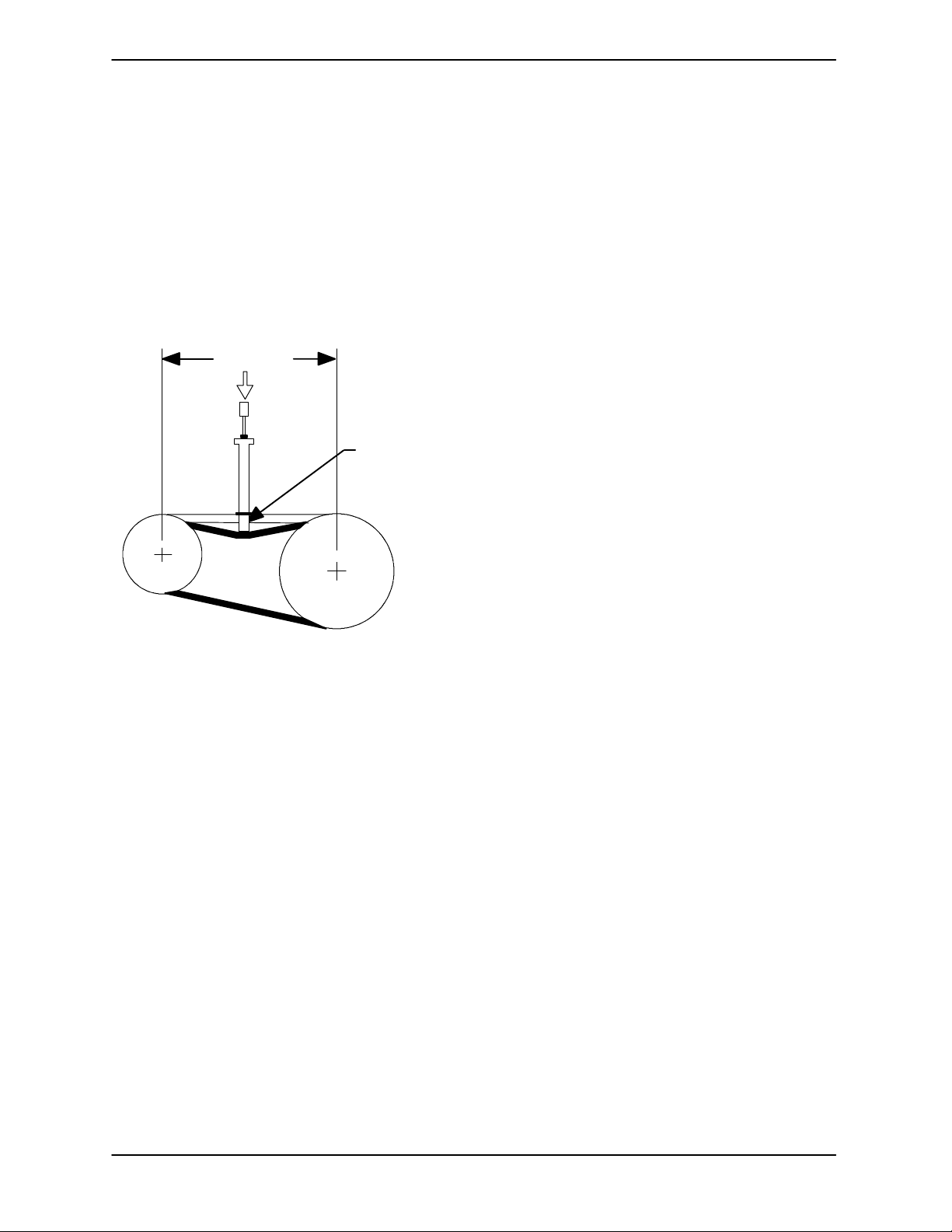
Belt Span
Deflection
Forexample,ifthespan asmeasured in FigureB-5
is32inches(813mm),the v-beltcross-sectionisC,
thesmallestsheavediameteris8inches,thepump
speed is 1250 RPM, and the belts are uncogged
Yy-Ttype, then 11.5 lbs. of force on the tensioner
should show 1/2-inch (12,7 mm) of deflection.
A tension tester is availableas an option fromGorman-Rupp (P/N 29513---001). Other tension testers are available from your local belt/sheave distributor, and work on a similar principal.
To use the Gorman-Rupp t ensioner, measure the
belt span as shown in Figure B-5. Position the bottomofthelargeO-ringonthespanscaleofthetensioner at the measured belt span. Setthe small Oring on the deflection force scale to zero.
Placethe tension tester squarely on the belt at the
center of the beltspan. Apply forceon theplunger,
perpendicular to the belt span, until the bottom of
thelargeO-ringisevenwith the top ofthenextbelt,
orwiththebottomofastraight edge laidacrossthe
sheaves.
Figure B-5. Belt Tension Measurement
The ratio of deflection to belt span is 1:64 for both
ASA and metric units. Therefore, a beltwith aspan
of 64 inches w ould require a deflection of 1 inch at
the force shown on the Tables for your particular
application.
Readtheforceappliedfromthe bottomofthesmall
O-ring on the deflection force scale. Compare this
forcewiththevalueshowninTableB-2orB-3and
adjust the tension accordingly. Note that the ten-
sion for new belts is higher than that for used
belts to allow for expected belt stretching. Do not
over-tension used belts t o the higher deflection
forces shown for new belts.
PAGE B -- 6
INSTALLATION
 Loading...