

GORMAN-RUPP PUMPS GHC SERIES Installation, Operation And Maintenance Manual
TVXY
OM---04352---01
September 2, 1996
INSTALLATION, OPERATION,
AND MAINTENANCE MANUAL
ROTARY GEAR PUMPS
MODELS
GHC SERIES
IRON AND STEEL
PUMPS
THE GORMAN-RUPP COMPANY MANSFIELD, OHIO
GORMAN-RUPP OF CANADA LIMITED ST. THOMAS, ONTARIO, CANADA Printed in U.S.A.
Copyright by the Go rman-Rupp Company

TABLE OF CONTENTS
INTRODUCTION PAGE I --- 1...................................................
S A F E T Y --- S E C T I O N A PA G E A --- 1............................................
I N S T A L L A T I O N --- S E C T I O N B PA G E B --- 1.....................................
GENERAL INFORMATION PAGE B--- 1......................................................
PUMP MODEL DESIGNATION PAGE B ---1..................................................
PREINSTALLATION INSPECTION PAGE B ---2................................................
STORAGE PA G E B --- 2....................................................................
Flushing PA G E B --- 2..................................................................
PUMP INSTALLATION P AGE B --- 3..........................................................
Lifting PA G E B --- 3.....................................................................
Po s i t io n i n g T h e Pu m p PA G E B --- 3......................................................
Mounting PA G E B --- 3.................................................................
Piping PA G E B --- 3....................................................................
Gauges PA G E B --- 4...................................................................
Strainers PA G E B --- 4..................................................................
Sealing PA G E B --- 4...................................................................
Valves PA G E B --- 4....................................................................
Barrier Liquids for Dual Seals PAGE B---4................................................
ALIGNMENT PA G E B --- 5..................................................................
C o u p l e d Dr i v e s PA G E B --- 5............................................................
V-Belt Drives PA G E B --- 5...............................................................
V-BELT TENSIONING PAGE B--- 6..........................................................
General Rules of Tensioning PAGE B---6.................................................
Tensioning Measurement PAGE B ---6...................................................
ELECTRICAL CONNECTIONS PAGE B--- 7...................................................
O P E R A T I O N --- S E C T I O N C PA G E C --- 1.......................................
P U M P O P E R AT I O N PA G E C --- 1............................................................
PRE-OPERATION PAGE C ---1..............................................................
Before Starting The Pump PAGE C --- 1...................................................
Checking Pump Rotation PAGE C ---1...................................................
STARTING PA G E C --- 1....................................................................
OPERATION PA G E C --- 2..................................................................
L i q u i d Te m p e r a t u r e PA G E C --- 2.........................................................
Overheating PA G E C --- 2...............................................................
Checking Gauges PA GE C --- 2..........................................................
Strainer Check PAGE C --- 2.............................................................
Leakage PA G E C --- 3..................................................................
PRESSURE RELIEF VALVE ADJUSTMENT PAGE C ---3........................................
Cracking Pressure PAGE C ---3.........................................................
Complete By-Pass Pressure PAGE C --- 3.................................................
STOPPING PA G E C --- 3....................................................................
T R O U B L E S H O O T I N G --- S E C T I O N D PA G E D --- 1...............................
PREVENTIVE MAINTENANCE PAGE D ---4...................................................
PUMP MAINTENANCE AND REPAIR --- SECTION E PAGE E --- 1.................
PART S KE Y:
Typical GHC Pump Model PAGE E ---3...................................................
i

TABLE OF CONTENTS
(continued)
ASSEMBLED GHC PUMP MODEL ILLUSTRATIONS PAGE E ---4...............................
P U M P D I S A S S E M B LY PA G E E --- 5..........................................................
Pressure Relief Valve (10) P AGE E --- 5...................................................
Rotor Adjusting Sleeve (07) PAGE E---6.................................................
Coverplate Kit (11) PAGE E--- 6.........................................................
Head/Idler Kit (01) PAGE E---6..........................................................
Seal Removal (05) PAGE E --- 7..........................................................
Rotor/Shaft Removal (08) PAGE E --- 7...................................................
Foot Bracket Kit (06) P AGE E -- -7........................................................
Backhead Kit Removal (06) PAGE E --- 7..................................................
Housing Assembly (04) PAGE E ---7.....................................................
PUMP REASSEMBLY PAGE E --- 8..........................................................
Cleaning and Inspection PAGE E ---8....................................................
Bushing Preparation PAGE E ---8........................................................
Housing Assembly (04) PAGE E ---8.....................................................
Backhead Kit (06) PAGE E---9..........................................................
Rotor/Shaft Assembly (03) PAGE E--- 9..................................................
Seal Installation (05) P AGE E --- 9........................................................
H e a d / I d le r K i t PA G E E --- 9..............................................................
Coverplate Kit (11) PAGE E---10........................................................
Foot Bracket Kit (08) PAGE E---10.......................................................
Rotor Adjusting Sleeve (07) PAGE E---10................................................
SETTING END CLEARANCE PAGE E--- 10...................................................
R E L I E F VA LV E DI S A S S E M B LY PA G E E --- 1 1.................................................
RELIEF VALVE REASSEMBLY PAGE E ---12..................................................
Relief Valve Installation (10) PAGE E --- 13................................................
SEAL APPENDIX --- SECTION F P AGE F--- 1...................................
Standard Friction Drive And Optional 60A, 60B And 61J Mechanical Seals PAGE F--- 1.............
StandardLip(AndOptional65C)Seal PAGEF---3.............................................
Positive Drive (Option 60D) And Metal Bellows (Option 60F, 61K) Seals PAGE F--- 5................
Double Friction Drive (Options 60J And 60K) Seals PAGE F--- 8.................................
Cartridge (Options 60M, 60N, 60P And 61L) Seals PAGE F--- 11.................................
Balanced Seal (Option 60Q) PAGE F---13....................................................
Friction Drive Mechanical Seal With Flush (Options 60T And 60U) P AGE F --- 15...................
ii

INTRODUCTION
OM--04352GHC SERIES
Thank You for purchasing a Gorman-Rupp Rotary
Gear Pump. This manual is designed to help you
achieve the best performance and longest life from
your Gorman-Rupp Rotary Gear pump. Read this
manual carefully to learn how to safely install, operate and repair your pump. Failure to do so could
result in personal injury or damage to the pump.
This manual will alert personnel to known procedures which require special attention, to those
which could damage equipment, and to those
which could be dangerous to personnel. However,
this manual cannot possibly provide detailed instructions and precautions for each specific application or for every situation that might occur during maintenance of the unit. Therefore, it is the responsibility of the owner, installer and/or maintenance personnel to ensure that applications and/
or maintenance procedures not addressed in this
manual are performed only
neither personal safety nor pump integrity are
compromised by such applications or procedures.
after establishing that
If there are any questions regarding the pump or
drive unit which are not covered in this manual or
in other literature accompanying this unit, please
contact your Gorman-Rupp distributor or the Gorman-Rupp Company:
The Gorman-Rupp Company
P.O. Box 1217
Mansfield, Ohio 44901-- 1217
or:
Gorman-Rupp of Canada Limited
70 Burwell Road
St. Thomas, Ontario N5P 3R7
RECORDING MODEL AND
SERIAL NUMBERS
Please record the pump model and serial number
in the spaces provided below. Your Gorman-Rupp
distributor needs this information when yourequire
parts or service.
In addition to this manual, a separate Parts List is
shipped with the pump. Refer to the Parts List when
ordering parts.
If your pump is furnished with a drive unit, refer to
the drive unit manufacturer’s installation and operation instructions in the literature accompanying
the pump.
These pumps can transfer a wide range of light,
medium, a nd heavy viscosity liquids, depending
on design and components. Some models are
not recommended for use with water; others
when fitted with specific options, may be used
with water; consult the factory.
Pump Model:
Serial Number:
WARRANTY INFORMATION
The warranty provided with your pump is part of
Gorman-Rupp’s support program for customers
who operate and maintain their equipment as described in this and the other accompanying literature. Please note that should the equipment be
abused or modified to change its performance beyond the original factory specifications, the warranty will become void and any claim will be denied.
INTRODUCTION
PAGE I -- 1
GHC SERIESOM--04352
The following are used to alert personnel to procedures which require special attention, to those which
could damage equipment, and to those which could be dangerous to personnel:
Immediate hazards which will result in
severe personal injury or death. These
instructions describe the procedure required and the injury which will result
from failure to follow the procedure.
Hazards or unsafe practices which
COULD result in severe personal injury
or death. These instructions describe
the procedure required and the injury
which could result from failure to follow
the procedure.
Hazards or unsafe practices whichCOULD
result in minor personal injury or productor
property damage. These instructions describe the requirements and the possible
damage which could result from failure to
follow the procedure.
NOTE
Instructions to aid in installation, operation, and
maintenance or which clarify a procedure.
PAGE I -- 2
INTRODUCTION
GHC SERIES OM--04352
SAFETY --- SECTION A
This information is specific to Gorman-Rupp GHC
Series Rotary Gear Pumps. It applies throughout
this manual and any manual or literature accompanying the pump.
In addition to this manual, see the separate literature covering the drive unit used to operate this
pump.
Pumps and related equipment must be installed and operated according to all national, local and industry standards.
This manual will alert personnel to
known procedures which require special attention, to those which could
damage equipment, and to those which
could be dangerous to personnel. However, this manual cannot possibly provide detailed instructions and precautions for each specific application or for
every situation that might occur during
maintenance of the unit. Therefore, it is
the responsibility of the owner, installer
and/or maintenance personnel to ensure that applications and/or maintenance procedures not addressed in this
manual are performed only after establishing that neither personal safety nor
pump integrity are compromised by
such applications or procedures.
covered in this manual could lead to destruction of equipment, injury, or death.
The standard version of this pump is designed to handle a wide range of light,
medium, and heavy vi scosity liquid, depending on design and components,
and a range of temperatures when fitted
with different seals. Do not apply at
higher temperatures that the seal will
handle. Do not attempt to pump liquids
which may damage the pump or endanger personnel as a result of pump failure; consult the factory for chemical
compatibility.
If the pump and motor are furnished
mountedon a base, make certain that all
lifting devices have adequate capacity.
If chains or cables are used in lifting,
make certain that they are positioned so
as not to damage components, and so
that the load will be balanced.
After the pump has been installed, make
certain that the pump and all piping or
hose connections are secure before operation. Loose connections can result in
damage to the equipment and serious
injury to personnel.
Before attempting to install, ope rate , or
service this pump, familiarize yourself
with this manual, and with all other liter ature ship ped with the pump. Unfamil iarity with all aspects of pump operation
SAFETY
Never operate the pump without a pressure relief valve installed on the pump
or in the discharge piping. Make certain
that pump-mounted pressure relief
PAGE A -- 1
OM--04352 GHC SERIES
valves are installed with their adjusting
ends toward the suction port.Ifbi-rotational operation is required, a pressure
relief device must be provided for both
directions of flow. Operation without a
pressure relief valve or with an improperly installed relief valve could cause
the pump to explode, resulting in serious injury or death to personnel.
An overheated pump can cause severe
burns and injury. If overheating occurs:
1. Stop the pump immediately.
2. Allow the pump to completely cool.
3. Refer to the instructions in this
manual before restarting the
pump.
Before attempti ng to open or service the
pump:
1. Familiarize yourself with this manual.
2. Lock out incoming power to the
drive unit to ensure that the pump
will remain inoperative.
3. Allow the pump to completely cool
Do not remove plates, covers, gauges,
pipe plugs or fittings from an overheated pump. Vapor pressure within the
pump can cause parts being disen gaged to be ejected with great force. Allow the pump to completely cool before
servicing.
if overheated.
4. Close the discharge and suction
valve (if used).
Do not operate this pump without
guards in place over the rotating parts.
Exposed rotating parts can catch clothing, fingers or tools, causing severe injury to personnel.
PAGE A -- 2
SAFETY
GHC SERIES
OM--04352
INSTALLATION --- SECTION B
GENERAL INFORMATION
Review all SAFETY information in Section A .
Pumps and related equipment must be installed and operated according to all national, local and industry standards.
Since pump installations are seldom identical, this
section is intended only to summarize general recommendations and practices required to inspect,
position, and arrange the pump and piping. If there
are any questions concerning your specific installation, contact your Gorman-Rupp distributor or
the Gorman -Rupp Company.
Most of the information applies to a flooded suction
installation where liquid is supplied under pressure.
Typ ica l Pu m p M o d e l
GHS 1 1/2 GF 32
Design
Style
Design Style: Gorman-Rupp rotary gear pumps
are available in five basic designs:
S G M C --- M e d i u m D u t y --- C o m p a c t
S G M S --- M e d i u m Du t y
S G H C --- H e a v y D u t y --- C o m p a c t
S G H S --- H e a v y Du t y
S G H A --- A b r a s i v e D u t y
Port Size: Gorman-Rupp rotary gear pumps are
available in port sizes from 1 to 6 inches, depending on the design style. Consult your GormanRupp distributor or the factory for additional sizes.
Port
Size
Hydraulic
Size
Construction
Code
If the pump is positioned above the liquid in a static
lift installation, information such as mounting, piping configuration and priming must be tailored to
specific conditions.
Thesepumpsarenotrecommendedfor
usewithwater.Somemodelswhenfitted
with specific options may be used with water; consult the factory.
PUMP MODEL DESIGNATION
Following is a description of the model numbering
system for Gorman-Rupp rotary gear pumps.
Rotary gear pump model numbers include design
style, port size, hydraulic size and construction
code.
Hydraulic Size: The first letter in the hydraulic size
is a rotor diameter code. The second letter indicates tooth length.
Construction Code: Construction Codes for Gorman-Rupp rotary gear pumps are as follows:
Code Description
3 Iron w/Mechanical Seal(s)
4Ironw/PackingorLipSeal(s)
9 316 SST w/Mechanical Seal(s)
10 316 SST w/Packing or Lip Seal(s)
32 Steel w/Mechanical Seal(s)
38 Steel w/Packing or Lip Seal(s)
Theoretical Displacement: Table B-1 indicates
theoretical displacement values for each hydraulic
size.
NOTE
Actual capacities and recommended shaft speeds
vary according to application. Consult your Gorman-Rupp distributor or the factory for addtional information.
INSTALLATION
PAGE B -- 1
GHC SERIESOM--04352
Ta b l e B -1 . T h eo r e ti c a l Di s p l a ce m e nt
Theoretical Displacement
Hydraulic
Size
DC 0.00568 21.486
DE 0.00704 26.646
GC 0.00967 36.619
GF 0.01405 53.186
GH 0.01915 72.479
GJ 0.02317 87.700
JG 0.03579 135.49
JJ 0.05159 195.28
JL 0.07078 267.94
JP 0.10078 381.48
NK 0.10665 403.71
NM 0.14173 536.51
NP 0.17681 669.31
RM 0.24030 909.65
RP 0.29979 1134.8
RR 0.35927 1360.0
RS 0.41876 1585.1
SR 0.65752 2489.0
SU 1.10240 4173.2
TU 1.91280 7240.7
Per Revolution
Gallons Centimeters
If the pump will not be immediately installed, follow
these procedures or damage to the pump will occur.
a. Do not flush the pump. Ensure that the port
3
plugs shipped with the pump remain in place
until piping is installed to help prevent dust or
other foreign objects from entering the pump.
b. Pumps that will not be installed for an ex-
tended period should be stored indoors if
possible. The factory-installed port plugs will
not ensure protection from excessive humidity, splash water or rain. In very humid or wet
conditions, install air-tight plugs in the ports
and fill the pump completelywith a lubricating
preservative liquid that is compatible with the
liquid to be pumped.
c. Pumps stored outdoors must be fully pre-
served as described above, completely covered with plastic or other water-tight material,
and the covering anchored to ensure that it
will not be blown off.
PREINSTALLATION INSPECTION
The pump assembly was inspected and tested before shipment from the factory. Before installation,
check for damage which may have occurred during shipment. Check as follows:
a. Inspect the pump assembly for cracks, dents,
damaged threads, and other obvious damage.
b. Check for loose attaching hardware. Since
gaskets tend to shrink after drying, check for
loose hardware at t he mating surfaces.
c. Carefully read all tags, decals, and markings
on the pump assembly, and perform all duties
indicated.
STORAGE
Flushing
Clean piping is essential because of closetolerance moving parts in this pump. Flush
all dirt, grit, weld beads or scale from the
suction piping before installing the pump.
Damage to the pump because of debris in
the suction line is not covered by the pump
warranty.
Before shipment, the pump may have been tested
using a petroleum-based preservative. If flushingis
required, do not do so until just before installation;
the test oil protects close-tolerance pump parts
from corrosion.
Due to the extreme close machining tolerances within rotary gear pumps, proper
storage before installation is essential to
prevent damage to the pump.
PAGE B -- 2
Most cleaning solvents are toxic and
flammable. Use them only in a well ventilated area free from flame, sparks, and
excessive heat. Read and follow all pre cautions printed on solvent containers.
INSTALLATION
GHC SERIES
OM--04352
To flush the pump, use an approved solvent compatible with the liquid being pumped. Make cer-
tain that the solvent will not attack pump components, particularly seals and gaskets.
PUMP INSTALLATION
Pump dimensions are shown in the separate
Pump Specification Bulletin.
Never operate the pump without a pressure relief valve installed on the pump
or in the discharge piping. Make certain
that pump-mounted pressure relief
valves are installed with their adjusting
ends toward the suction port.Ifbi-rotational operation is required, a pressure
relief device must be provided for both
directions of flow. Operation without a
pressure relief valve or with an improperly installed relief valve could cause
the pump to explode, resulting in serious injury or death to personnel.
Lifting
Remove suction and discharge hose and piping
before attempting to lift the pump. Use liftingequipment with a capacity of a t least five times the total
weight of the equipment being lifted.
Positioning The Pump
Piping
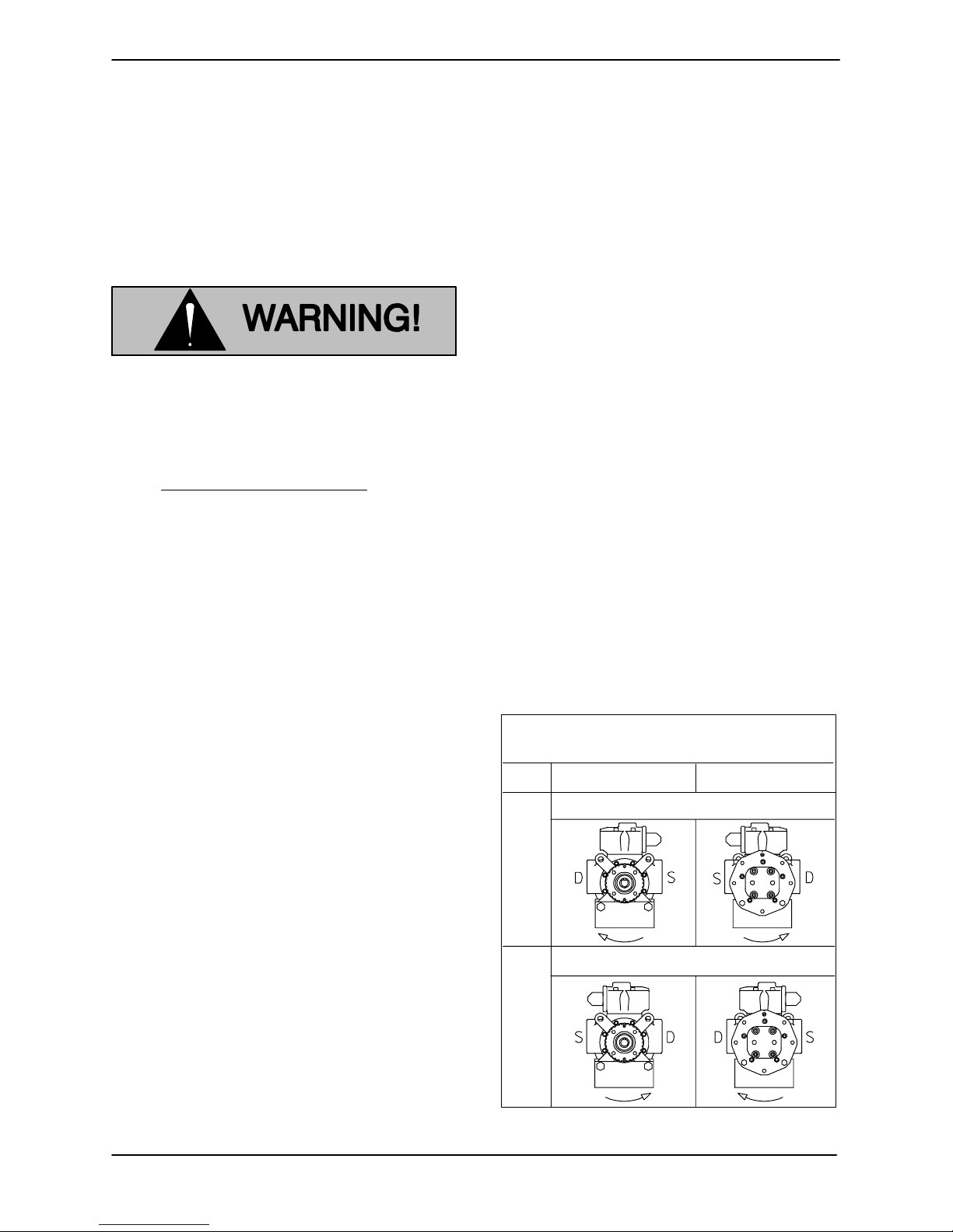
Before establishing suction and discharge lines,
determine pump port positions and rotation. Figure B ---1 shows typical port positions for the standard 180_ housing; if you have selected a 90_
housing port option, your port positions will be different.
Either hose or rigid pipe may be used to make connections. If rigid piping is used, install expansion
joints to protect the pump from vibration and thermal expansion in the piping. Do not use expansion
joints or flexible connectors to adjust misaligned
piping.
Begin piping layout at the pump, and work toward
the source of supply and the point of discharge. If
an obstacle is in the way of a suction or discharge
line, run the piping around the obstruction, not
over it. Running piping over an obstruction will
creat an air pocket which will make priming more
difficult.
If possible, slope the piping toward the pump so no
air or liquid is trapped in the piping. If a long horizontal suction line is necessary, install the line below the liquid level whenever possible in order to
keep the piping full of liquid. This will make priming
easier because the pump will not have to remove
as much air in the line.
Housing Position Std. 180_ Pump
(3---9 O’clock) Housing Mounted Relief Valve
OPT.
Drive End Front End
Rotation Clockwise
Locate the pump as close as possible to the liquid
being pumped. Locating the pump below the liquid source will help self-priming and reduce the
possibility of cavitation.
Mounting
The pump may be shipped alone, mounted on a
base, or with pump and motor mounted on a base.
Install the pump and motor on a base before
mounting the base on a foundation.
Mount the base on a foundation that will provide
permanent, rigid support for the pump, and will be
heavy enough to absorb any vibration, strain or
shock.
INSTALLATION
STD.
Rotation Counter-clockwise
01A
Figure B-1. Typical Port Positions & Rotation
PAGE B -- 3

GHC SERIESOM--04352
The discharge and suction lines must be independently supported to avoid vibration and strain
on the pump. For maximum pumping capacity,
keep the lines as short and straight as possible. Elbows and fittings used in the lines increase friction
losses; minimize their use. Reducers used in suction lines should be the eccentric type installed
with the flat part uppermost to avoid creating air
pockets.
Before tightening a connection or flange, align it
exactly with the pump port. Never pull a pipe line
into place by tightening the flange bolts and/or
couplings.
Gauges
Install a vacuum gauge in the suction line and a discharge pressure gauge in the discharge line (both
should be as close as possible to the pump) to
monitor operation and assist in troubleshooting.
Toprevent leakage during shutdown, install a shut off valve in the discharge line, particularly on a
flooded suction application. Shutoff valves are not
recommended for suction lines.
It is not recommended that a foot valve be installed
at the end of the suction line. If desired to install a
foot valve, consult the factory.
When handling very hot or cold liquids, install a
pressure relief valve in any part of the system that
can be valved off or isolated; this will protect piping
against damage from liquid thermal expansion or
contraction from temperature changes during
shutdown.
Barrier Liquids for Dual Mechanical Seals
Pumps equipped with dual (tandem) mechanical
seals require a barrier liquid to prevent contamination of the seal assembly by the liquid being
pumped. The barrier liquid must have the following
characteristics:
Strainers
Because of the close-tolerance moving parts of
this pump, it is recommended that a strainer be installed in the suction line. The strainer should be
large enough to prevent excessive vacuum, and
capable of operating under high vacuum without
collapsing. The net open area of the strainer
screen depends on liquid viscosity and desired
flow rate; in any case, the sum of the area of all the
holes in the screen should be three to five times the
area of the suction pipe.
Sealing
Even a slight leak will affect priming, head, and capacity, especially in a suction lift application. Seal
all piping joints, valves and gauges with pipe dope
or teflon tape. The sealing material s hould be compatible with the liquid being pumped.
Val ves
a. The barrier liquid must have sufficient lubricat-
ing characteristics, including an optimum viscosity of 1 to 5 cSt at the temperature of the
liquid being pumped.
b. The barrier liquid must be compatible in all re-
spects with all pump and seal components to
which it will be exposed.
c. The barrier liquid must be compatible in all re-
spects w ith the liquid being pumped.
Pumps equipped with dual mechanical seals require the barrier liquid to be supplied at a continuous pressure equivalent to the maximum dis charge pressure in order to avoid inboard seal face
separation. The maximum barrier liquid pressure
that can be applied depends primarily on the maximum seal design pressure (consult the factory).
Do not pressurize tandem seals. Pressurizing a
tandem seal w ill cause the seal faces to separate,
resulting in leakage and/or damage to the seal.
To avoid air pockets, install piping valves with the
stem horizontal.
PAGE B -- 4
Refer to the appropriate section in Seal Appendix,
Section F for your specific seal option for operating
instructions for the barrier liquid reservoir kit.
INSTALLATION
GHC SERIES
ARA
A
V
ALIGNMENT
Make certain that power to the drive unit
is disconnected be fore attempting to
connect the pump drive; otherwise, personal injury may result.
OM--04352
NOTE
See ROTATION in Section C before mounting the
pump on the base.
Coupled Drives
When using couplings, the axis of the power
source must be aligned to the axis of the pump
shaft in both the horizontal and vertical planes.
Most couplings require a specific gap or clearance
between the driving and the driven shafts. Refer to
the coupling manufacturer’s service literature.
Align spider insert type couplings by using calipers
to measure the dimensions on the circumference
of the outer ends of the coupling hub every 90_.
The coupling is in alignment when the hub ends
are the same distance apart at all points (see Figure B-2).
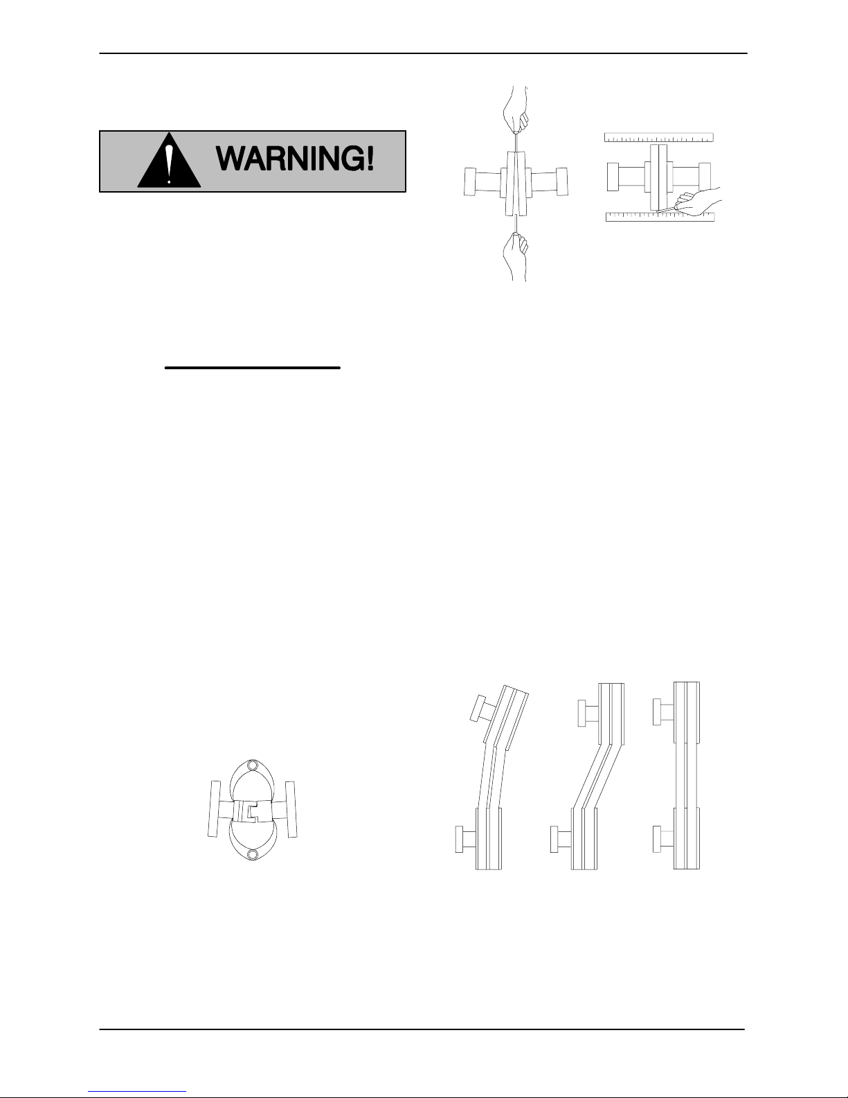
Figure B-3. Aligning Non-Spider Type Coupling
Check parallel adjustment by laying a straightedge
across both coupling rims at the top, bottom, and
side. When the straightedge rests evenly on both
halves of the coupling, the coupling is in horizontal
parallel alignment. If the coupling is misaligned,
use a feeler gauge between the coupling and the
straightedge to measure the amount of misalignment.
V-Belt Drives
When using V-belt drives, the power source and
the pump must be parallel. Use a straightedge
along the sides of the pulleys to ensure that they
are properly aligned (see Figure B-4). In drive systems using two or more belts, make cert ain that the
belts are a matched set; unmatched sets will cause
accelerated belt wear.
Figure B-2. Spider-type Couplings
Align n on-spider t ype couplings by using a feeler
gauge or taper gauge between the couplinghalves
every 90_. The coupling is in alignment when the
hubs are the same distance apart at all points (see
Figure B-3).
INSTALLATION
MISALIGNED:
SHAFTS
NOT P
LLEL
MISALIGNED:
SHAFTS
NOT IN LINE
ALIGNED: SHAFTS
PARALLEL AND
SHE
ES IN LINE
Figure B-4. V-belt Alignment
Tighten t he belts in accordance with the belt manufacturer’s instructions. If the belts are too loose
they will slip; if they are too tight, there will be excessive power loss and possible bearing failure.
PAGE B -- 5
GHC SERIESOM--04352
Select pulleys to match the proper speed ratio;
overspeeding the pump may damage both pump
and power source.
Do not operate this pump without
guards in place over the rotating parts.
Exposed rotating parts can catch clothing, fingers or tools, causing severe injury to personnel.
V-BELT TENSIONING
General Rules of Tensioning
For new v-belts, check the tension after 5, 20 and
50 hours of operation and re-tension as required
(see the following procedure for measuring belt
tension). Thereafter, check and re-tension if required monthly or at 500 hour intervals, whichever
comes first.
Ideal v-belt tension is the lowest tension at which
the belt will not slip under peak load conditions. Do
not over-tension v-belts. Over-tensioning will shorten both v-belt and bearing life. Under-tensioning
will cause belt slippage. Always keep belts free
from dirt, grease, oil and other foreign material
which may cause slippage.
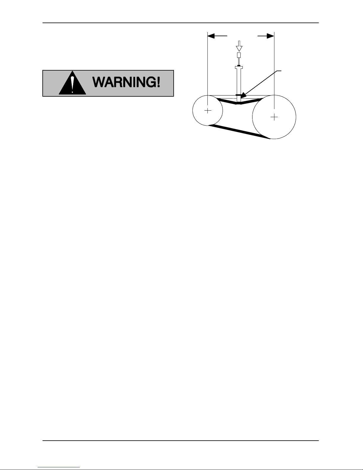
Tension Measurement
Belt Span
Deflection
Figure B-5. Belt Tension Measurement
The ratio of deflection to belt span is 1:64 for both
ASA and metric units. Therefore, a belt with a span
of 64 inches would require a deflection of 1 inch at
the force shown on the Tables for your particular
application.
For example, if the span as measured in Figure B-5
is 32 inches (813 mm), the v-belt cross-section is C,
the smallest sheave diameter is 8 inches, the pump
speed is 1250 RPM, a nd the belts are uncogged
Yy-T type, then 11.5 lbs. of force on the tensioner
should show 1/2-inch (12,7 mm) of deflection.
A tension tester is available as an option from Gorman-Rupp (P/N 29513---001). Other tension tes ters are available from your local belt/sheave distributor, and work on a similar principal.
To use the Gorman-Rupp tensioner, measure the
belt span as shown in Figure B-5. Position the bottom of the large O-ring on the span scale of the tensioner at the measured belt span. Set the small Oring on the deflection force scale to zero.
Place the tension tester squarely on the belt at the
center of the belt span. Apply force on the plunger,
perpendicular to the belt span, until the bottom of
the large O-ring is even with the top of the next belt,
or with the bottom of a straight edge laid across the
sheaves.
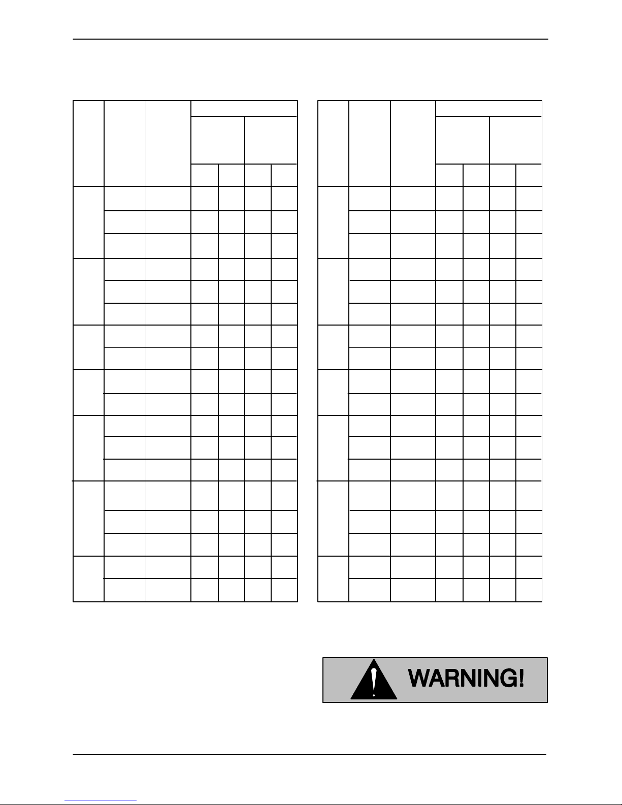
Correct v-belt tension can be achieved using a vbelt tension tester and Table B-2 or B-3. Use the
tables to find the v-belt size (cross-section), the
smallest sheave diameter, the belt type for your application. The corresponding deflection force required for new or used belts is shown opposite the
RPM range of the pump.
PAGE B -- 6
Read the force applied from the bottom of the small
O-ring on the deflection force scale. Compare this
forcewiththevalueshowninTableB-2orB-3and
adjust the tension accordingly. Note that the ten-
sion for new belts is higher than that for used
belts to allow for expected belt stretching. Do not
over-tension used belts to the higher deflection
forces shown for new belts.
INSTALLATION
GHC SERIES
OM--04352
TableB-2.SheaveDiameter (In.)
Smallest
Cross
Section
Sheave
Diameter
Range
3.0 - 3.6
A,AX
B,BX
C,CX
3V,
3VX
5V,
5VX
8V
3.8 - 4.8
5.0 - 7.0
3.4 - 4.2
4.4 - 5.6
5.8 - 8.6
7.0 - 9.0
9.5 - 16.0
12.0 - 16.0
D
18.0 - 20.0
2.2 - 2.4
2.65 - 3.65
4.12 - 6.90
4.4 - 6.7
7.1 - 10.9
11.8 - 16.0 500-1740
12.5 - 17.0
18.0 - 22.4
Deflection Force (Lbs.)
Belt Deflection Force
Uncogged
Hy-T Belts &
Uncogged
Hy-T Torque
Tea m
R.P.M.
Range
1000-2500
2501-4000
1000-2500
2501-4000
1000-2500
2501-4000
860-2500
2501-4000
860-2500
2501-4000
860-2500
2501-4000
500-1740
1741-3000
500-1740
1741-3000
200-850
851-1500
200-850
851-1500
1000-2500
2501-4000
1000-2500
2501-4000
1000-2500
2501-4000
500-1749
1750-3000
3001-4000
500-1740
1741-3000
1741-3000
200-850
851-1500
200-850
851-1500
Used
Belt
3.7
2.8
4.5
3.8
5.4
4.7
5.3
4.5
6.3
6.0
11.5
9.4
14.1
12.5
11.5
9.4
30.4
25.6
3.6
3.0
4.9
4.4
12.7
11.2
15.5
14.6
33.0
26.8
39.6
35.3
New
Belt
5.5
4.2
6.8
5.7
8.0
7.0
7.9
6.7
9.4
8.9
17.0
13.8
21.0
18.5
17.0
13.8
45.2
38.0
5.1
4.4
7.3
6.6
18.9
16.7
23.4
21.8
49.3
39.9
59.2
52.7
Cogged
Tor q u e - F le x
&Machined
Edge torque
Tea m B e lt s
Used
New
Belt
Belt
4.1
6.1
3.4
5.0
5.0
7.4
4.3
6.4
5.7
9.4
5.1
7.4
4.9
7.2
4.2
6.2
10.5
7.1
9.1
7.1
8.5
12.6
7.3
10.9
21.8
14.7
17.5
11.9
15.9
23.5
14.6
21.6
21.8
14.7
17.5
11.9
3.3
4.9
2.9
4.3
6.2
4.2
5.6
3.8
5.3
7.9
4.9
7.3
10.2
15.2
8.8
13.2
5.6
8.5
22.1
14.8
20.1
13.7
17.1
25.5
16.8
25.0
TableB-3.SheaveDiameter (Mm.)
Deflection Force (Kg.)
Belt Deflection Force
Uncogged
Hy-T Belts &
Uncogged
Hy-T Torque
Tea m
Used
Belt
1.7
1.3
2.0
1.7
2.4
2.1
2.4
2.0
2.9
2.7
5.2
4.3
6.4
5.7
11.3
9.6
13.8
11.6
1.6
1.4
2.2
2.0
5.8
5.1
7.0
6.6
15.0
12.2
18.0
16.0
Cross
Section
A,AX
B,BX
C,CX
D
3V,
3VX
5V,
5VX
8V
Smallest
Sheave
Diameter
Range
75 - 90
91 - 120
125 - 175
85 - 105
106 - 140
141 - 220
175 - 230
231 - 400
305 - 400
401 - 510
55 - 60
61 - 90
91 - 175
110 - 170
171 - 1275
276 - 400 500-1740
315 - 430
431 - 570
R.P.M.
Range
1000-2500
2501-4000
1000-2500
2501-4000
1000-2500
2501-4000
860-2500
2501-4000
860-2500
2501-4000
860-2500
2501-4000
500-1740
1741-3000
500-1740
1741-3000
200-850
851-1500
200-850
851-1500
1000-2500
2501-4000
1000-2500
2501-4000
1000-2500
2501-4000
500-1749
1750-3000
3001-4000
500-1740
1741-3000
1741-3000
200-850
851-1500
200-850
851-1500
New
Belt
2.5
1.9
3.1
2.6
3.6
3.2
3.6
3.0
4.3
4.0
7.7
6.3
9.5
8.4
16.8
14.2
20.5
17.2
2.3
2.0
3.3
3.0
8.6
7.6
10.6
9.9
22.4
18.1
26.8
23.9
Cogged
Tor q u e - F le x
&Machined
Edge torque
Tea m B e lt s
Used
New
Belt
Belt
1.9
2.8
1.5
2.3
2.3
3.4
2.0
2.9
2.6
4.3
2.3
3.4
2.2
3.3
1.9
2.8
4.8
3.2
4.1
3.2
3.9
5.7
3.3
4.9
9.9
6.7
7.9
5.4
7.2
10.7
6.6
9.8
1.5
2.2
1.3
2.0
2.8
1.9
2.5
1.7
2.4
3.6
2.2
3.3
4.6
6.9
4.0
6.0
2.5
3.9
10.0
6.7
9.1
6.2
7.8
11.6
7.6
11.3
ELECTRICAL CONNECTIONS
Before connecting an electric motor to incoming
power, check that the electrical service available
matches the pump motor requirements stamped
on the motor nameplate.
INSTALLATION
The electrical power used to operate
this pump is high enough to cause injury or death. Obtain the services of a qu-
PAGE B -- 7

GHC SERIESOM--04352
alified electrician to make all electrical
connections.
Do not install and operate a non-explosion proof motor in an explosive atmo-
sphere. Install, connect, and operate
the motor in accordance with The National Electrical Code and all local
codes. If there is a conflict between the
instructions in the manual accompanying the unit and The Nati onal Electrical
Code or the applicable local c ode, The
National or local code shall take precedence.
PAGE B -- 8
INSTALLATION
GHC SERIES OM--04352
OPERATION --- SECTION C
Review all SAFETY information in Section A .
Follow the instructions on all tags, labels and
decals attached to the pump.
PUMP OPERATION
Never use a pressure relief valve to regulate liquid flow. Pressure relief valves
are designed as safety devices only
.Attempting to regulate flow with a pres sure relief valve may cause the pump or
piping to explode, causing severe personal injury or death.
PRE-OPERATION
Make certain that all instructions in INSTALLATION, Section B have been carried out.
Open all valves in the suction and discharge lines,
and close all drain valves.
If your pump is equipped with a packing seal, loosen the gland nuts before starting the pump until the
packing gland may be moved slightly. If leakage
seems excessive after starting, wait until the pump
has run long enough to reach its normal operating
temperature before adjusting the gland nuts. Do
not over-tighten the gland nuts. Packing pumps
must leak slightly to cool and lubricate the shaft
and to allow the shaft to turn freely.
Consult the drive manufacturer’s operating manual before attempting to start t he drive.
In a suction lift application, fill the pump housing
with liquid to seal clearances and to lubricate the
pump.
Checking Pump Rotation
Correct rotation of your pump is shown on the
pump serial plate or direction arrow plate.
The standard version of the pump is designed to handle a wide range of light, medium, and heavy viscosity liquids, depending on design and components. Do notoperate the pump with higher liquid temperatures than what it was designed; otherwise,
pump components and operation may be
affected. For temperature range consult
The Gorman-Rupp Company.
Before Starting The Pump
Never operate the pump against a
closed suction or discharge valve. The
pump will overheat, and may rupture or
explode, causing personal i njury or
death.
In applications with a single direction of
flow and a single pump-mounted pressure
relief valve, make certain that the drive unit
turns the pump in the correct direction of
rotation. Otherwise, the pump-mounted
pressure relief valve will not function.
Follow the drive unit manufacturer’s instructions,
jog the pump motor briefly, and check rotation.
If a 3-phase motor is being used and rotation is incorrect, have a qualified electrician interchange
any two of the 3-phase wires to change the direction of rotation. If a 1-phase motor is being used
and rotation is incorrect, consult the motor manufacturer’s literature.
STARTING
Start the drive unit as indicated in the manufacturer’s instructions and observe the suction and discharge gauges. If the pump does not deliver liquid
OPERATION
PAGE C -- 1
 Loading...