

Page 1
ACEG
OM---05171---OE01
January 5, 2001
INSTALLATION, OPERATION,
AND MAINTENANCE MANUAL
WITH P ARTS LIST
60 SERIES PUMP
MODEL
62 1/2D1---CH23 S/G
THE GORMAN-RUPP COMPANY D MANSFIELD, OHIO
GORMAN-RUPP OF CANADA LIMITED D ST.THOMAS, ONTARIO, CANADA Printed in U.S.A.
ECopyright by the Gorman-Rupp Company
Page 2

The engine exhaust from this
product contains chemicals
known to the State ofCaliforniato
cause cancer, birth defects or
other reproductive harm.
Page 3

TABLE OF CONTENTS
INTRODUCTION PAGE I --- 1...................................................
SA F E TY --- S E CTIO N A PA G E A --- 1............................................
IN S TA LLATIO N --- SECTIO N B PA G E B --- 1.....................................
Pump Dimensions PAGE B --- 1.....................................................
PREINSTALLATION INSPECTION PAGE B --- 1............................................
POSITIONING PUMP PA GE B --- 2.......................................................
Mounting PA GE B --- 2.............................................................
SUCTION AND DISCHARGE PIPING PAGE B --- 2.........................................
Materials PA GE B --- 2..............................................................
Line Configuration PAGE B --- 2......................................................
Connections to Pump PAGE B --- 2..................................................
Gauges PA GE B --- 2...............................................................
SUCTION LINES PAGE B --- 3...........................................................
Fittings PA GE B --- 3...............................................................
Strainers PA GE B --- 3..............................................................
Sealing PAGE B --- 3...............................................................
Suction Lines In Sumps PAGE B --- 3.................................................
Suction Line Positioning PAGE B --- 3................................................
DISCHARGE LINES PA GE B --- 4........................................................
Siphoning PA GE B --- 4.............................................................
Valves PA GE B --- 4................................................................
OP E R AT ION --- S E CTIO N C PA G E C --- 1.......................................
PRIMING PA GE C --- 1.................................................................
Exhaust Primer PAGE C --- 1........................................................
STARTING PA GE C --- 1................................................................
OPERATION PA GE C --- 2..............................................................
Leakage PAGE C --- 2..............................................................
Liquid Temperature And Overheating PAGE C --- 2.....................................
Strainer Check PAGE C --- 2.........................................................
Pump Vacuum Check PAGE C --- 2..................................................
STOPPING PA GE C --- 2................................................................
Cold Weather Preservation PAGE C --- 3..............................................
TROU BLESH OOT I NG --- S E CTIO N D PA G E D --- 1...............................
PREVENTIVE MAINTENANCE PAGE D --- 2..................................................
PUMP MAINTENANCE AND REPAIR --- SECTION E PAGE E --- 1.................
STANDARD PERFORMANCE CURVE FOR PUMP MODEL 62 1/2D1---CH23 S/G PAGE E --- 1..
PARTS LIST:
Pump Model PA GE E --- 3..........................................................
Pump End Assembly PAGE E --- 5...................................................
Exhaust Primer Assembly PAGE E --- 6...............................................
PUMP AND SEAL DISASSEMBLY AND REASSEMBLY PAGE E --- 7.........................
i
Page 4

TABLE OF CONTENTS
(continued)
Discharge Check Valve Disassembly PAGE E --- 7.....................................
Exhaust Primer Disassembly PAGE E --- 7............................................
Pump Disassembly PAGE E --- 7.....................................................
Seal Removal and Disassembly PAGE E --- 8..........................................
Seal Reassembly and Installation P AGE E --- 8........................................
Impeller Installation P AGE E --- 10.....................................................
Pump Reassembly PAGE E --- 10.....................................................
Exhaust Primer Reassembly PAGE E --- 10.............................................
Discharge Check Valve Reassembly PAGE E --- 11......................................
LUBRICATION PA GE E --- 11.............................................................
Seal Assembly PAGE E --- 11.........................................................
Engine PA GE E --- 11................................................................
ii
Page 5
60 SERIES
OM--05171
INTRODUCTION
This Installation, Operation, and Maintenance
manual is designed to help you achieve the best
performance and longest life from your GormanRupp pump.
This pump is a 60 Series, single-stage centrifugal
model designed for agriculturalor fire fighting service.Itis close-coupledto aKohler CH23v-twin cylinder O.H.V. air cooled gasoline engine and protected by a wrap-around roll cage with rubber
mounting feet. The pump features compact, light
The Gorman-Rupp Company or Gorman-Rupp of Canada Limited
P.O. Box 1217 70 B urwell Road
Mansfield, Ohio 44901-- 1217 St. Thomas, Ontario N5P 3R7
For information or technical assistance on the engine, contact the engine manufacturer’s local dealer or
representative.
The following are used to alert maintenance personnel to procedures which require special attention, to
those which could damage equipment, and to those which could be dangerous to personnel:
weight design for portability, as well as rugged
construction for easy, low-cost maintenance. The
basic material of construction for wetted parts is
aluminum w ith bronze wear ring, and a self lubricated mechanical seal.
Ifthereare anyquestionsregardingt he pumporits
applicationwhichare notcovered inthis manualor
in other literature accompanying this unit, please
contact your Gorman-Rupp distributor, or write:
Immediate hazards whichWILL result in
severe personal injury or death. These
instructions describe the procedure required and the injury which will result
from failure to follow the procedure.
Hazards or unsafe practices which
COULDresult in severe personal injury
or death. These instructions describe
the procedure required and the injury
which could result from failure to follow
the procedure.
HazardsorunsafepracticeswhichCOULD
result in minor personal injury or product
or property damage. These instructions
describe the requirements and the possibledamage which couldresult fromfailure
to follow the procedure.
NOTE
Instructions to aid in installation, operation,and
maintenance, or which clarify a procedure.
PAGE I -- 1INTRODUCTION
Page 6
60 SERIES OM--05171
SAFETY --- SECTION A
This information applies to 60 Series
Engine Drivenpumps. Refer to themanual accompanying the engine be fore attempting to beg in operation.
This manual will alert personnel to
known procedures which require special attention, to those which c ould
damage equipment, and to thosewhich
could be dangerous to personnel.However, thismanualcannotpossiblyanticipate and provide detailed instructions
and precautions for every situationthat
might occur during maintenance of the
unit.Therefore,itisthe responsibility of
the owner/maintenance personnel to
ensurethatonlysafe, established maintenance procedures are used, and that
any procedures not addressed in this
manual are performed only after establishing that neither personal safety nor
pump integrity are compromised by
such practices.
Beforeattemptingto openorservicethe
pump:
This pump is designed to handle clear
water for high pressure distribution. Do
not attempt to pump volatile,corrosive,
or flammable liquids which may damagethepump orendanger personnel as
a result of pump failure.
Do not operate the pump against a
closed discharge valve for long periods
of time. This could bring the liquid to a
boil, build pressure, and cause the
pump casing to rupture or explode.
Do not remove plates, covers, gauges,
pipe plugs, or fittings from an overheated pump. Vaporpressure withinthe
pump can cause parts being disengagedtobe ejectedwith great force.Allow the pump to cool before servicing.
1. Familiarize yourself with thismanual.
2. Shutdown the engine and disconnect the park plug wires to ensure
that the pump will remain inoperative.
3. Allowthe pump tocompletely cool
if overheated.
4. Check the temperature before
opening any covers, plates, or
plugs.
5. Close the suction and discharge
valves.
6. Vent the pump slowly and cautiously.
7. Drain the pump.
Do not operate an internal combustion
engine in an explosive atmosphere.
When operating internal combustion
engines in an enclosed area, make certain that exhaust fumes are piped tothe
outside. These fumes contain carbon
monoxide, a deadly gas that is colorless, tasteless, and odorless.
Fuel used by internal combustion engines presents an extreme explosion
PAGE A -- 1SAFETY
Page 7

OM--05171
and fire hazard. Make certain that all
fuel lines are securely connected and
free of leaks. Never refuel a hot or running engine. Avoid overfilling the fuel
tank.Alwaysusethe correcttype offuel.
60 SERIES
Never tamper with the governor to gain
more power. The governor establishes
safe operating limits that should not be
exceeded.
PAGE A -- 2 SAFETY
Page 8
INSTALLATION --- SECTION B
OM--0517160 SERIES
Review all SAFETY information in Section A .
Since pump installations are seldom identical,this
section offers only general recommendations and
practices required to inspect, position, and arrange the pump and piping.
Most of the information pertains to a standard
static lift application where the pump is positionedabovethefreelevelofliquidto bepumped.
If installed in a flooded suction application where
the liquid is supplied to the pump under pressure,
some of the information such as mounting, line
configuration, and priming must be tailored to the
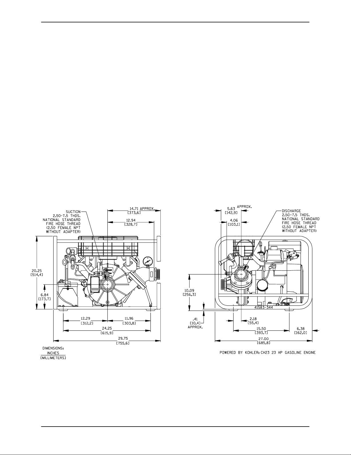
OUTLINE DRAWING
specific application. Since the pressure supplied
to the pump is critical to performance and safety,
be sure to limit the incoming pressure to 50% of
the maximum permissible operating pressure as
shownon thepump performance curve. (SeeSection E, Page 1.)
Forfurtherassistance, contact yourGorman-Rupp
distributor or the Gorman-Rupp Company.
Pump Dimensions
SeeFigure1fortheapproximatephysicaldimensions of this pump and engine.
Figure 1. Pump Model 62 1/2D1--CH23 S/G
PREINSTALLATION INSPECTION
Thepump assemblywas inspectedandtested before shipment from the factory. Before installation,
inspect the pump for damage which may haveoc curred during shipment. Check as follows:
a. Inspect thepumpforcracks, dents,damaged
threads, and other obvious damage.
b. Check for and tighten loose attaching hard-
ware. Since gaskets tend to shrink after drying, check for loose hardware at mating surfaces.
PAGE B -- 1INSTALLATION
Page 9

OM--05171 60 SERIES
c. Carefully read all tags, decals and markings
onthepumpassembly,andfollowtheinstructions indicated.
d. Check all lubricant levels and lubricate as
necessary. Refer to LUBRICATION in the
MAINTENANCE AND REP AIRsectionof this
manual and perform duties as instructed.
e. If the pump and engine have been stored for
more than 12 months, some of the components or lubricants may have exceeded their
maximumshelflife.These mustbeinspected
or replaced to ensure maximum pump service.
f. Check to ensure the following standard
equipment items are included with the pump
assembly:
S Portable 6.5 gallon fuel tank complete with
quick-connect fitting.
S Suction strainer.
S Rubber foot mounting kit (must be
installed). Toinstall feet, positionflatwashers on capscrews, slide the capscrews
through the rubber feet and holes in the
base,and secure withtheflanged hexnut.
If the maximum shelf life has been exceeded, or if
anything appears to be abnormal, contact your
Gorman-Rupp distributor or the factory to determine the repair or updating policy. Do not put the
pump into service until appropriate action has
been tak en.
POSITIONING PUMP
This pump is designed to be very light-weightand
portable. The total pump weight is approximately
240 pounds (109 kg), not including accessories
orengine fuel.Customer installedequipment such
as suctionand discharge hoses must be removed
before attempting to lift.
Mounting
Locatethepump inanaccessibleplaceascloseas
practicalto the liquidbeingpumped. Levelmounting is essential for proper operation.
To ensure sufficient lubrication and fuel supply to
the engine, do not position the pump and engine
morethan 15_ off horizontal for continuous operation. The pump and engine may be positioned up
to 30_ off horizontal for intermittent operation
only;however,theengine manufacturershould be
consulted for continuous operation at angles
greater than 15_.
SUCTION AND DISCHARGE PIPING
Pump performance is adversely effected by increased suction lift, discharge elevation, and friction losses. See the performance curve and operating range shown on Page E-1 to be sure your
overall application allows pump to operate within
thesafeoperationrange.
Materials
Either pipe or hose maybe used for suction and
discharge lines; however, the materials must be
compatiblewiththe liquidbeingpumped. Ifhoseis
used in suction lines, it must be the rigid-wall, reinforced type to prevent collapse under suction. Using piping couplings in suction lines is not recommended.
Line Configuration
Keep suction and discharge lines as straight as
possible to minimize friction losses. Make minimum use of elbows and fittings, which substantiallyincreasefrictionloss. Ifelbows arenecessary,
use the long-radius type to minimize friction loss.
Connections to Pump
Before tightening a connecting flange, align it exactlywith the pump port. Never pulla pipe lineinto
place by tightening the flange bolts and/or couplings.
Lines near the pump must be independently supported to avoid strain on the pump which could
cause excessive vibration, decreased bearing life,
and increased shaft and seal wear. If hose-type
linesare used,they shouldhaveadequatesupport
to secure them when filled with liquid and under
pressure.
The pump may have to be supported orshimmed
to provide for level operation or to eliminate vibration.
PAGE B -- 2 INSTALLATION
Gauges
Most pumps are drilled and tapped for installing
dischargepressureandvacuumsuctiongauges.If
Page 10

OM--0517160 SERIES
these gauges are desired for pumps that are not
tapped, drill and tap the suction and discharge
lines not less than 18 inches (457,2 mm) from the
suction and discharge ports and install the lines.
Installationcloserto the pump may result inerratic
readings.
SUCTION LINES
Toavoidair pocketswhichcouldaffectpump priming, thes uction line must be as short and direct as
possible.Whenoperationinvolvesasuctionlift,the
line must always slope upward to the pump from
the source of the liquid being pumped; if the line
slopes down to the pump at any point along the
suction run, air pockets will be created.
The maximum vertical suction lift for this pump is
20 feet (6,1 meters). It is not designed to be operated at a higher lift.
Fittings
Suction lines should be the same size as the pump
inlet. If reducers are used in suction lines, they
should be the eccentric type, and should be installedwith the flat part of the reducers uppermost
to avoid creating air pockets. Valves are not normally used in suction lines, but if a valve is used,
install it with the stem horizontal to avoid air pock ets.
Strainers
Sealing
Since even a slight leak will affect priming, head,
and capacity, especially when operating with a
high suction lift, all connections in the suction line
should be sealed with pipe dope to ensure an airtight seal. Follow the sealant manufacturer’s recommendations when selecting and applying the
pipe dope. The pipe dope should be compatible
with the liquid being pumped.
Suction Lines In Sumps
If a single suction line is installed in a sump, it
should be positioned away from the wall of the
sumpata distance equal to1 1/2 times the diameter of the suction line.
If there is a liquid flow from an open pipe into the
sump, the flow should be kept away from the suctioninlet because theinflowwillcarryair downinto
the sump, and air entering the s uction line will reduce pump efficiency.
Ifitis necessary to positioninflowclose to the suctioninlet, installa bafflebetween theinflowandthe
suction inlet at a distance 1 1/2 times the diameter
of the suction pipe. The baffle will allow entrained
air to escape from the liquid before it is drawn into
the suction inlet.
If two suction lines are installed in a single sump,
theflow pathsmay interact,reducing theefficiency
of one or both pumps. To avoid this, position the
suction inlets so that they are separated by a distance equal to at least 3 times the diameter of the
suction pipe.
If a strainer is furnished with the pump, be certain
touse it;any sphericalsolidswhichpassthrougha
strainer furnished with the pump will also pass
through the pump itself.
If a strainer is not furnished with the pump, but is
installed by the pump user, make certain that the
total area of the openings in the strainer is at least
three or four times the cross section of the suction
line,and that the openings willnot permit passage
of solids larger than the solids handling capability
of the pump.
This pump is designed to handle up to 5/ 16-inch
(7,9 mm) diameter spherical solids.
Suction Line Positioning
The depth of submergence of the suction line is
critical to efficient pump operation. Figure 2shows
recommended minimum submergence vs. veloc-
ity.
NOTE
The pipe submergence required may be reduced
by installing a standard pipe increaserfitting at the
endof the suctionline. The largeropening size will
reduce the inlet velocity. Calculate the required
submergence using the following formula based
on the increased opening size (area or diameter).
PAGE B -- 3INSTALLATION
Page 11

OM--05171 60 SERIES
Figure 2. Recommended Minimum Suction Line Submergence vs. Velocity
DISCHARGE LINES
Siphoning
Donot terminate the discharge lineat a level lower
than that of the liquid being pumped unless a siphon breaker is used in the line. Otherwise, a siphoning action causing damage to the pump
could result.
Valves
A check valveinthedischargelineis normally recommended, but it is not necessary in low discharge head applications.
If a throttlingvalve is desired inthe discharge line,
useavalveaslargeasthelargestpipetominimize
friction losses. Never install a throttling valve in a
suction line.
Withhighdischarge heads,itis recommendedthat
a throttling valve and a system check valve be installed in the discharge line to protect the pump
from excessive shock pressure and reverse rotation when it is stopped.
PAGE B -- 4 INSTALLATION
Page 12

60 SERIES
OM--05171
OPERATION --- SECTION C
Review all SAFETY information in Section A .
Follow the instructions on all tags, labels and
decals attached to the pump.
This pump is designed to handle clear
water in high pressure distribution. Do
not attempt to pump volatile,corrosive,
or flammable liquids which may damagethepump orendanger personnel as
a result of pump failure.
Never tamper with the governor to gain
more power. The governor establishes
safe operating limits that should not be
exceeded.
The exhaust primer utilizes engine exhaust gases,
directedthrough a venturi,to createa vacuum and
draw air out of the suction line and pump casing.
The exhaust primer is capable of priming a pump
with a maximum priming lift of 15 feet (4,6 meters)
within 90 seconds; less time will be required for
priming ata lesser lift.Ifthe pump doesnotprimein
a reasonablelengthoftime, check the suctionline
for leaks.
Toprime the pump, closethe throttling valve inthe
discharge line.
Close the exhaust primer handle (see Figure 1),
and open the cock in the priming line. Consult the
starting instructions in this manual as well as the
engine operating manual, and start the engine.
Operate the engine at maximum governed speed
and allow the pump to prime untilliquid flows continuously from the exhaust primer nozzle. When
the pump is fullyprimed, open the exhaust primer
handle, and close the cock in the priming line.
PRIMING
Install the pump and piping as described in INSTALLATION. Make sure that the piping connec-
tions are tight, and that the pump is securely
mounted. Check that the pump is properly lubricated (see LUBRICATION in MAINTENANCE
AND REPAIR).
Exhaust Primer
Since this pump is not self-priming, it is equipped
with an exhaust primer assembly (Figure 1).
HANDLE
GAS COCK
Once fully primed, reduce the engine speed and
partially open the discharge throttling valve. The
discharge line should be filled slowly to prevent
damage tothe piping, gaskets, and other devices,
resulting from the initial shock of liquid filling the
lines. When the discharge line is completely filled,
adjust the discharge throttling valveto the desired
flow rate.
STARTING
Consult the operations manual furnished with the
engine.
Attach the fuel line to the quick-connect fitting locatedon theengine. Positiontheportable fueltank
atthesamelevelasthepump,orslightlyhigher.
Squeezetheprimingbulbuntilthefuelcanbeseen
in the transparent fuel line at the carburetor inlet.
The transparent fuel line need not be completely
full. Fuel will be pulled into the carburetor while
cranking the engine w ith the choke on.
Figure 1. Exhaust Primer Assembly
OPERATION PAGE C -- 1
Set the ignition toggle switch to the ON position.
Page 13

60 SERIESOM--05171
Set the twist-lock throttle control at approximately
half open position. Start the engine and follow engine manufacturer’s recommendations for carburetoradjustmentsto obtainoptimumperformance.
NOTE
Hard starting may be experienced after connecting
a new tank of fuel. This can be caused by air
trapped in the fuel line. It is recommended that the
fuel line be vented and filled by depressing the
valve in the female quick connect fitting prior to
installing it on the pump.
OPERATION
Pump speed and operating condition
points must be within the continuous performance range shown on the curve. (See
Section E, Page 1.)
heated pump. Vaporpressure withinthe
pump can cause parts being disengagedtobe ejectedwith great force.Allowthe pump to completely coolbefore
servicing.
Strainer Check
If a suction strainer has been shipped with t he
pump or installed by the user, check the strainer
regularly, and clean it as necessary. The strainer
shouldalsobe checkedifpumpflowratebeginsto
drop. If a vacuum suction gauge has been installed, monitor and record the readings regularly
to detect strainer blockage.
Never introduce air or steam pressure into the
pump casingor piping to removea blockage.This
could result in personal injury or damage t o the
equipment. If backflushing is absolutely necessary, liquid pressure must be limited to 50% of the
maximum permissible operating pressure shown
on the pump performance curve. (See Section E,
Page 1.)
Leakage
No leakage should be visibleat pump mating surfaces, or at pump connections or fittings. Keepall
lineconnectionsand fittingstight tomaintain maximum pump efficiency.
Liquid Temperature And Overheating
The maximum liquid temperature for this pump is
160_F(71_C). Do not applyit ata higher operating
temperature than is recommended.
Overheating can occur if operated with the valves
in the suction or discharge lines closed. Operating
against closed valves could bring the liquid to a
boil, build pressure, and cause the pump to rupture or explode. If overheating occurs, stop the
pumpand allowit tocompletelycool beforeservicing it. Refill the pump casing with cool liquid.
Pump Vacuum Check
Withthe pump inoperative,installa vacuumgauge
in the system, using pipe dope on the threads.
Block the suction lineandstart thepump. Atoperating speed the pump should pull a vacuum of 20
inches (508,0 mm) or more of mercury. If it does
not, check for air leaks in the seal, gasket, or discharge valve.
Openthe suctionline,andread thevacuum gauge
with the pump primed and at operation speed.
Shut offthe pump. The vacuumgaugereading will
immediately drop proportionate to static suction
lift,andshouldthenstabilize. Ifthe vacuum reading
falls off rapidly after stabilization, an air leak exists.
Before checking for the source of the leak, check
the point of installation of the vacuum gauge.
STOPPING
Do not remove plates, covers, gauges,
pipe plugs, or fittings from an over-
Never halt the flow of liquid suddenly. If the liquid
being pumped is stopped abruptly, damaging
shock waves can be transmitted to the pump and
piping system. Close all connectingvalvesslowly.
OPERATIONPAGE C -- 2
Page 14

60 SERIES
If the application involves a high discharge
head, gradually close the discharge
throttling valve before stopping the pump.
Afterstoppingthe pump,switchoffthe engineignition and remove or ground the spark plug to ensure that the pump will remain inoperative.
Cold Weather Preservation
In below freezing conditions, drain the pump to
OM--05171
preventdamagefrom freezing. Also,clean outany
solids by flushing with a hose. Operate the pump
for approximatelyone minute; this willremoveany
remaining liquid that could freeze the pump rotating parts. If the pump will be idle for more than a
few hours, or if it has been pumping liquids containing a large amount of solids, drain the pump,
and flush it thoroughly with clean water. Toprevent
large solids from clogging the drain port and preventing the pump from completely draining, insert
a rod or stiff wire in the drain port, and agitate the
liquid during the draining process. Clean out any
remaining solids by flushing with a hose.
OPERATION PAGE C -- 3
Page 15

60 SERIES
OM--05171
TROUBLESHOOTING --- SECTION D
Review all SAFETY information in Section A .
Beforeattemptingto openorservicethe
pump:
1. Familiarize yourself with thismanual.
2. Shutdown the engine and remove
thesparkplug wires toensurethat
the pump will remain inoperative.
Table B-1 Troubleshooting Chart
TROUBLE
ENGINE FAILS TO
START
CAUSE REMEDY
Auxiliary priming device faulty
or improperly installed.
Integral discharge check
valve clogged or binding.
Spark plug contaminated.
3. Allowthe pump tocompletely cool
if overheated.
4. Vent the pump slowly and cautiously.
5. Close the suction and discharge
valves.
6. Check the temperature before
opening any covers, plates, or
plugs.
7. Drain the pump.
Forspecificinstructionson enginetroubleshooting
or repair, see the engine manual.
Repair priming device or check installation.
Clean valve.
Clean and replace plug; reset gap.
PUMP FAILS T O
PRIME
No fuel to engine or fuel contaminated.
Engine flooded.
Auxiliary priming device faulty
or improperly installed.
Integral discharge check
valve clogged or binding.
Air leak in suction line.
Lining of suction hose col-
lapsed.
Leakingorwornsealorpump
gasket.
Suction lift or discharge head
to high.
Strainer clogged.
Check fuel tank level; vent t ank; purge air
from fuel lie; clean fuel filters. Check fuel for
proper oil mix; check for contamination.
Dry spark plug; a djust carburetor; see engine
manual.
Repair priming device or check installation.
Clean valve.
Correct leak.
Replace suction hose.
Check pump vacuum. Replace leaking or
worn seal or gasket.
Check piping installation and reduce suction
lift and/or discharge head.
Check strainer and clean if necessary.
TROUBLESHOOTING PAGE D -- 1
Page 16

OM--05171
TROUBLE
PUMP STOPS OR
FAILS TO DELIVER
RATED FLOW OR
PRESSURE
Table B-1 Troubleshooting Chart (continued)
CAUSE REMEDY
Air leak in suction line.
Suction intake not submerged
at proper level or sump too
small.
Correct leak.
Checkinstallationand correct submergenceas
needed.
60 SERIES
Lining of suction hose collapsed.
Dischargelinecloggedorrestricted; hose kinked.
Impellerorotherwearingparts
worn or damaged.
Impeller clogged.
Pump speed too slow.
Suction lift or discharge head
to high.
Leakingorwornsealorpump
gasket.
PUMP REQUIRES
TOO MUCH POWER
Exceeding operating limits.
Liquid solution too thick.
PREVENTIVE MAINTENANCE
Sincepump applicationsareseldomidentical,and
pump wear is directly affected by such things as
the abrasive qualities, pressure and temperature
oftheliquidbeingpumped, thissection isintended
only to provide general recommendations and
practices for preventive maintenance. Regardless
of the application however,following a routine preventive maintenance schedule will help assure
trouble-free performance and long life from your
Gorman-Rupp pump. For specific questions concerning your application, contact your GormanRupp distributor or the Gorman-Rupp Company.
Record keeping is an essential component of a
good preventive maintenance program. Changes
in suction and discharge gauge readings (if so
Replace suction hose.
Check discharge lines; straighten hose.
Replace worn or damaged parts. Check that
impelleris properlycentered and rotates freely.
Free impeller of debris.
Check engineoutput; consult engineoperation
manual.
Check pipinginstallationand reduce suctionlift
and/or discharge head.
Check pump vacuum. Replace leaking orworn
seal or gasket.
See performance curve in Pump Maintenance
And Repair.
Dilute if possible.
equipped) between regularly scheduled inspections can indicate problems that can be corrected
before system damage or catastrophic failure occurs.The appearanceof wearingpartsshouldalso
bedocumented ateach inspectionfor comparison
as well. Also, if records indicate that a certain part
(such as the seal) fails at approximately the same
duty cycle, the part can be checked and replaced
beforefailureoccurs,reducing unscheduleddown
time.
For new applications, a first inspection of wearing
partsat250 hourswillgiveinsightintothewearrate
foryourparticularapplication.Subsequentinspections should be performed at the intervals shown
on the chart below. Critical applications should be
inspected more frequently.
TROUBLESHOOTINGPAGE D -- 2
Page 17

60 SERIES
OM--05171
Preventive Maintenance Schedule
Service Interval*
Item
General Condition (Temperature, Unusual
Noises or Vibrations, Cracks, Leaks,
Loose Hardware, Etc.) I
Pump Performance (Gauges, Speed, Flow) I
Bearing Lubrication I R
Seal Lubrication (And Packing Adjustment,
If So Equipped) I R
V-Belts (If So Equipped) I
Air Release Valve Plunger Rod (If So Equipped) I C
Front Impeller Clearance (Wear Plate) I
Rear Impeller Clearance (Seal Plate) I
Check Valve I
Pressure Relief Valve (If So Equipped) C
Pump and Driver Alignment I
Shaft Deflection I
Bearings I
Bearing Housing I
Piping I
Driver Lubrication - -- See Mfgr’s Literature
Daily Weekly Monthly Semi-
Annually
Annually
Legend:
I = Inspect, Clean, Adjust, Repair or Replace as Necessary
C= Clean
R= Replace
* Service interval based on an intermittent duty cycle equal to approximately 4000 hours annually.
Adjust schedule as required for lower or higher duty cycles or extreme operating conditions.
TROUBLESHOOTING PAGE D -- 3
Page 18

60 SERIES
OM--05171
PUMP MAINTENANCE AND REPAIR --- SECTION E
MAINTENANCE AND REPAIR OF THE WEARING PARTS OF THE PUMP WILL MAINTAIN PEAK
OPERATING PERFORMANCE.
STANDARD PERFORMANCE FOR PUMP MODEL 62 1/2D1--CH23 S/G
Based on 70_ F(21_ C) clear water at sea level
with minimumsuction lift.Since pump installations
areseldomidentical,yourperformancemaybe different due to such factors as viscosity, specific
gravity, elevation, temperature, and impeller trim.
formance or part numbers.
Never tamper with the governor to gain
If your pump serial number is followed by an “N”,
your pump is NOT astandardproductionmodel.
Contact the Gorman-Rupp Company to verifyper-
MAINTENANCE & REPAIR PAGE E -- 1
more power. The governor establishes
safe operating limits that should not be
exceeded.
Page 19

SECTION DRAWING
60 SERIESOM--05171
Figure 1. Pump Model 62 1/D1---CH23 S/G
MAINTENANCE & REPAIRPAGE E -- 2
Page 20

60 SERIES
OM--05171
PARTS LIST
Pump Model 62 1/2D1---CH23 S/G
(From S/N 1211015 up)
Ifyourpump serialnumber is followedby an “N”,your pumpis NOT a standard production model.Contact
the Gorman-Rupp Company to verify part numbers.
ITEM
PART NAME PART
NO.
NUMBER
MAT’L
CODE
QTY ITEM
NO.
PART NAME PART
NUMBER
MAT’L
CODE
QTY
1 PUMP END ASSY 62 1/2D1---(CH23) 1
2 KOHLER CH23PS ENGINE 29127---303 --- --- --- 1
3 ROLLOVER BASE 41583---344 24150 1
4 MUFFLER ASSY 46211---029 24150 1
5 MUFFLER GUARD KIT 29187---111 ------ --- 1
6 PR ESSUR E G AUG E S1 80 --- --- --- 1
7 HAND CARRY DECAL 2613FT --------- 2
8 DISCHARGE STICKER 6588BJ --- --- --- 1
9 SUCTION STICKER 6588AG --- ------ 1
10 COUPLING 2469 14000 2
11 EXHAUST PRIMER ASSY 46112---706 --- --- --- 1
12 WARNING DECAL 2613FE --- --- --- 1
13 BRACKET 34144---036 15080 1
14 FLAT WASHER K06 15991 1
15 HEX HD CAPSCREW B0603 15991 1
16 HEX NUT D06 15991 1
17 DISCONNECT BUSHING 26534---082 --- --- --- 1
18 DUST CAP 26531---301 ------ --- 1
19 JAM NUT AT06S 15991 1
20 FUEL LINE 11308H --- ------ 1
21 HOSE CLAMP S1788 --- --- - -- 2
22 HEX HD CAPSCREW B0606 15991 4
23 FLAT WASHER K06 15991 4
24 FLANGED HEX NUT 21765---314 ------ --- 4
25 STUD C0709 15991 4
26 HEX NUT D07 15991 4
27 LOCKWASHER J07 15991 4
28 RUBBER FOOT MTG KIT 48152---603 ------ -- - 1
29 ---RUBBER BUMPER S1224 --- --- --- 4
30 ---HEX HD CAPSCREW B0504 15991 4
31 ---FLAT WASHER K05 15991 4
32 ---FLANGED HEX NUT 21765---312 --- -- ---- 4
33 NAME PLATE 2613BF 13990 1
34 DRIVE SCREW BM#04---03 17000 4
35 B AT TE R Y B OX A S SY GR P 40 --- 0 5 --- --- --- 1
36 ---HEX HD CAPSCREW B0503 15991 4
37 ---T TYPE LOCKWASHER BL05 15991 1
38 ---FLANGED HEX NUT 21765---312 --- -- ---- 4
39 ---BATTERY BOX 11281 24000 1
40 ---BATTERY S1680 - -- ------ REF
41 ---BATTERY TAG 38818---680 ------ --- 1
42 ---BATTERY BOX COVER 11870 24000 1
43 ---HEX HD CAPSCREW B0504 15991 2
44 ---FLANGED HEX NUT 21765---312 --- -- ---- 2
45 ---GROUND CABLE 47311---542 --- ------ 1
46 ---POS BATTERY CABLE 47311---502 --------- 1
47 FUEL TANK ASSY 46711---086 --- --- -- - 1
NOT SHOWN:
STRAINER 26841---010 - -- ------ 1
ADAPTOR 26115---011 --- --- --- 1
EXHAUST PRIMER TAG 6588X --- - -- --- 1
INSTRUCTION TAG 38817---045 ------ --- 1
ENG START---UP TAG 38816---269 --- --- --- 1
INDICATES PARTSRECOMMENDED FOR STOCK
MAINTENANCE & REPAIR PAGE E -- 3
Page 21

SECTION DRAWING
60 SERIESOM--05171
Figure 2. 62 1/2D1---(CH23) Pump End Assembly
MAINTENANCE & REPAIRPAGE E -- 4
Page 22

60 SERIES
OM--05171
PARTS LIST
62 1/2D1---(CH23) Pump End Assembly
ITEM
NO.
1 PUMP CASING 11013 13040 1
2
3
4 STUD C0605 1/2 15991 12
5 HEX NUT D06 15991 12
6 INTERMEDIATE 38264---331 13040 1
7
8
9
10
11 CASING DRAIN PLUG P04 15079 1
12
13 CHECK VALVE BODY 6323 13000 1
14
15 CHECK VALVE ARM 6324 14000 1
16 STUD C1009 15991 4
17 HEX NUT D10 15991 4
18 SPRING HOLDER 25273---273 ------ --- 1
PART NAME
IMPELLER 38623---034 13047 1
SEAL ASSEMBLY 25271---903 ------ --- 1
IMPELLER ADJUSTING SHIM 37J 17090 1
SHAFT SLEEVE 3428D 16000 1
BALANCE RING 62ZL6 14000 1
CASING GASKET 11013G 18000 1
WEAR RING 11017 14050 1
CHECK VALVE BODY GASKET 6323G 19060 1
PART
NUMBER
MAT’L
CODE
QTY
INDICATES PARTS RECOMMENDED FOR STOCK
MAINTENANCE & REPAIR PAGE E -- 5
Page 23

60 SERIESOM--05171
Figure 3. Exhaust Primer Detail
ITEM
NO.
1 EXHAUST PRIMER VALVE BODY 3643 10010 1
2
3
4 EJECTOR BODY 3552 14000 1
5 VENTURI 2345B 14000 1
6 HEX NIPPLE 26112---053 --- ------ 1
7 SWIVEL FITTING 26571---002 ------ --- 1
8 HOSE ADAPTOR 26523---334 ------ --- 2
9 1 FT HOSE 18513---302 ------ --- 1
10 GAS COCK S2 --- --- --- 1
11 VALVE HAND 1458A 15990 1
12 EXH PRIMER DECAL 6588AS --- ------ 1
13 EXHAUST PRIMER VALVE 1467 10010 1
14 COTTER PIN M0406 15990 2
15 SPRING WASHER S165 --- --- --- 3
PART NAME
PIPE NIPPLE T08 15079 1
EJECTOR JET 3645B 14000 1
PART
NUMBER
MAT’L
CODE
MAINTENANCE & REPAIRPAGE E -- 6
QTY
Page 24

60 SERIES
OM--05171
PUMP AND SEAL DISASSEMBLY
AND REASSEMBLY
Review all SAFETY information in Section A .
Followtheinstructionsonall tags,label anddecals attached to the pump.
This pump requires little service due to its rugged,
minimum-maintenance design. However, if it becomesnecessarytoinspect orreplacethe wearing
parts, followthese instructionswhichare keyed to
thesectionalview (seeFigure1)andthe accompanying parts list.
Most service functions, such as wear plate, impeller, and seal replacement, may be performed by
draining the pump and removing the back cover
assembly. However, the following instructions assume complete disassembly is required.
As described in the SAFETY Section, this manual
willalert personnel toknown procedures which require special attention, to those which could damage equipment, and to those whichcould be dangerousto personnel. However,this manualcannot
possibly anticipate and provide detailed precautions for every situation that might occur during
maintenanceof theunit. Therefore,itis theresponsibilityof the owner/maintenance personnel toensure that only safe, established shop procedures
are used, and that any procedures not addressed
in this manual are performed only after establishing that neither personal safety nor pumpintegrity
are compromised by such practices.
2. Shut down the engine and remove
the spark plug wires to ensurethat
the pump will remain inoperative.
3. Allowthe pump tocompletely cool
if overheated.
4. Check the temperature before
opening any covers, plates, or
plugs.
5. Close the suction and discharge
valves.
6. Vent the pump slowly and cautiously.
7. Drain the pump.
Discharge Check Valve Disassembly
(Figure 2)
Removethenuts(17)andseparatethecheckvalve
body(13)fromthe pumpcasing(1). Pullthe rubber
gasket (14) fromthe flangestuds (16),andpull the
check valve arm (15) from the check valve body.
Unscrewthepressuregaugeandfirehoseadaptor
if required.
Clean the mating surfaces of both flanges and inspectall partsfor wearor damage. Ifno furtherdisassembly is required, refer to Discharge Check
Valve Reassembly.
Exhaust Primer Disassembly
(Figure 3)
Removethe hoseadaptor (8)fromtheswivelfitting
(7). If necessary, remove the gas cock valve (10)
andpipenipple(6).
Before attempting to service the pump, switch off
the engine ignition and remove the spark plug, or
take other precautions to ensure thatit will remain
inoperative. Close all valves in the suction and discharge lines.
Forengine disassembly and repair, consult the literature supplied with the engine, or contact your
local Kohler engine representative.
To remove the exhaust primer body (1) unscrew
the body from the muffler (4). To disassemble the
exhaust primer, remove the handle (11) and unscrew the various primer components.
If no further disassembly is required, refer to Ex-
haust Primer Reassembly.
Pump Disassembly
(Figure 2)
After disconnecting the exhaust primer, remove
the casing drain plug (11) and drain the pump casing. Clean and reinstall the plug.
Beforeattemptingto openorservicethe
pump:
1. Familiarize yourself with thismanual.
MAINTENANCE & REPAIR PAGE E -- 7
For access to the impeller (2) and seal assembly
(3), removethe nuts (5) securingthe pumpcasing
totheintermediate(6).Removethecasinggasket
(10) and clean the contacting surfaces.
Page 25

60 SERIESOM--05171
Inspect the wear ring (12) for excessive wear or
damage.Thewearringissecuredinthepumpcasing by a press fit. If replacement is required, use a
small bit to drill two holes horizontally through the
ring, 180_ apart. Use a chisel or other suitable tool
to complete the cuts through the ring and remove
thering fromthe casing.Be carefulnotto damage
the casing bore w hen removing the ring.
Toremovethe impeller,insert a steel baror drift pin
between the vanes, and turn the impeller in a
counter-clockwise direction (when facing the impeller)whileholdingthe enginecrankshaft stationary. Be careful notto damage the impeller vanes.
Use caution when unscrewing the impeller; tension on the seal spring will be released as the impeller is removed.
Inspect t he balance ring (9) for excessive wear or
damage. The balance ring is secured in the intermediate by a press fit. If replacement is required,
use a small bit to drill two holes horizontally
through the ring, 180_ apart. Use a chisel or other
suitable toolto completethe cuts through the ring
and remove t he ring from the intermediate. Be
careful notto damagethe intermediatebore when
removing the ring.
Seal Removal and Disassembly
(Figure 2 And 4)
Removethe springholder(18) andthe impelleradjustingshims(7). Tieandtag theshims ormeasure
and record their thickness for ease ofreassembly.
Removethe seals pring, then slidethe shaft sleeve
and rotating portion of the seal off the engine shaft
as a unit. Apply oil to the sleeve and work it up under the bellows. Slide the rotating portion of the
sealoff the sleeve. Use two stiff wires with hooked
ends to pullthe stationary seat from the intermediate bore.
NOTE
Analternatemethodof removing thestationaryseat
istoremove thehardware(26 and27,Figure 1)and
separate the intermediate from the engine. Use a
dowel to press the stationary seat from the intermediate.
If no further disassembly is required, refer to Seal
Reassembly And Installation.
Seal Reassembly and Installation
(Figure 2 And 4)
Cleanthe seal cavityandshaft witha cloth soaked
in fresh cleaning solvent.
Most cleaning solvents are toxic and
flammable. Usethem only in a well ven tilated area free from excessive heat,
sparks, and flame. Read and follow all
precautions printed on solventcontainers.
The sealis not normallyreused because wear patterns on the finished faces cannot be realigned
during reassembly. This could result in premature
failure.Ifnecessary toreuse anoldsealinanemergency, carefully wash all metallic parts in fresh
cleaning solvent and allow to dry thoroughly.
Handlethe seal parts with extreme care to prevent
damage. Be careful not to contaminate precision
finished faces; even fingerprints on the faces can
shortenseallife.Ifnecessary,cleanthefaceswitha
non-oilbased solvent and a clean, lint-free tissue.
Wipe lightly in a concentric pattern to avoid
scratching the faces.
Inspect the seal components for wear, scoring,
grooves,and otherdamage that mightcauseleakage.Clean andpolishtheshaft sleeve,or replaceit
if there are cuts or nicks on either end. If any components are worn, replace the complete seal;
never mix old and new seal parts.
If a replacement seal is being used, remove itfrom
the container and inspect the precision finished
faces to ensure that they are free of any foreign
matter.
To ease installation of the seal, lubricate the rotating element O-ring with water or a very small
amount of oil, and apply a drop of light lubricating
oil on the finishedfaces. Assemble the seal as follows,(seeFigure4).
MAINTENANCE & REPAIRPAGE E -- 8
Page 26

60 SERIES
OM--05171
IMPELLER
IMPELLER
SHIM SET
SPRING
RETAINER
BELLOWS
O-RING
INTERMEDIATE
SHAFT
SLEEVE
IMPELLER
SHAFT
STATIONARY
ELEMENT
ROTATING
ELEMENT
Figure 4. 25271--903 Seal Assembly
This seal is not designed for operation at
temperatures above 160_F(71_C). Donot
use at higher operating temperatures.
If the balance ring (9) was removed, the replacement ring should be pressed into the intermediate
beforeinstallingthe seal. Positionthe ring inthe intermediatebore withthechamferedendtoward toward the bore shoulder and press it into the bore
until fully seated.
NOTE
The balance ring must be fully seated in the intermediate bore, otherwise binding and/or excessive
wear could result.
Lubricate the stationary seat O-ring with light oil
andinstallit inthestationary seat.Use thumbpressure to press this subassembly into the intermediateboreuntilfullyseated.Be carefulnottodamage
thesealface.Afterinstallation,wipethesealfacein
a concentric pattern with a clean, lint-free cloth to
remove any fingerprints.
Secure the intermediate to the engine with the
hardware (26 and 27). Be careful not to damage
the stationary seat on the shaft threads.
Slide the rotating portion of the seal (consisting of
theretainer,bellowsand rotatingelement)ontothe
sleeve(8)untiltherotatingfaceisjust flush with
the chamfered end of the sleeve. Slide the sleeve
ontotheshaftuntilthesealfaces contact.Continue
topushthesleevethroughthesealuntilitseats
against the shaft shoulder.
Iftheintermediatewasremoved,layitonaflatsurface with the impeller side facing up.
MAINTENANCE & REPAIR PAGE E -- 9
Install the seal spring. Make sure that all components of the seal are seated squarely.
Page 27

60 SERIESOM--05171
Impeller Installation
(Figures 2 and 5)
Inspectthe impeller(2), and replace itif cracked or
badly worn.
CD
B
2
AB
B
+
A
2
For maximum pump efficiency, the impeller must
becentered withinthe volutescroll. Toverifyimpeller positioning, measure the pump casing and impeller as shown in Figure 5. Use these measurements to calculate the required impeller location
(dimension E). Add or remove impeller adjusting
shims (55) to obtain dimension E.
D
2
E
Step 2Step 1 Step 3
C
+
D
2
=
E
---
Figure 5. Centering Impeller Within Pump Casing
NOTE
After the impeller has been properly positioned,
check for free rotation. Correct any scraping or
binding before further reassembly.
Pump Reassembly
(Figure 2)
If the wear ring (12) was removed, apply ‘Loctite
No. 242 Threadlocker’ or equivalent compound)
between thecasing andthewearring. Positionthe
replacement ring in the casing bore so that chamfer on the I.D. faces toward the impeller. Press the
ringinto the bore until fullyseatedagainst the casing shoulder.
NOTE
The wear ring must be fully seated in the casing
bore, otherwise binding and/or excessive wear
could result.
Install the pump casing gasket (10). Carefully
guidethewearringintotheeyeoftheimpeller,and
securethecasing to the intermediatewith the nuts
(5).
NOTE
After the pump casing has been install check the
impeller for free rotation. Correct any scraping or
binding before further reassembly.
Exhaust Primer Reassembly
(Figure 3)
NOTE
Before assembly, apply pipe sealant on all
threaded joints.
To install t he exhaust primer body (1) screw the
body intothe muffler(4). To assemble theexhaust
primer,installthehandle(11)and installthevarious
primer components.
Screw the hose adaptor (8) into the swivel fitting
(7). Install the gas cock valve (10) and pipenipple
(6).
MAINTENANCE & REPAIRPAGE E -- 10
Page 28

60 SERIES
OM--05171
Discharge Check Valve Reassembly
(Figure 2)
Position the pivot of the check valve arm (15) in the
slotinthevalvebody (13).Installtherubber gasket
(14), and secure the assembly to the casing with
the nuts (17). Check for free operation of the valve
arm.Inspectthepressuregaugeandhoseadaptor
forwearordamagebeforeinstallationandreplace
as required.
LUBRICATION
Seal Assembly
(Figure 2)
Theseal assemblyis lubricatedbythemediumbeing pumped. No addition lubrication is required.
Engine
(Figure 1)
Refer to the literature provided with the engine, or
contact your local Kohler engine representative.
MAINTENANCE & REPAIR PAGE E -- 11
Page 29

For U.S. and International Warranty Information,
Please Visit www.grpumps.com/warranty
or call:
U.S.: 419−755−1280
International: +1−419−755−1352
For Canadian Warranty Information,
Please Visit www.grcanada.com/warranty
or call:
519−631−2870
THE GORMAN-RUPP COMPANY D MANSFIELD, OHIO
GORMAN-RUPP OF CANADA LIMITED D ST. THOMAS, ONTARIO, CANADA
 Loading...