

Gorman-Rupp Pumps 86A2-F4L User Manual
ACE
OM---00957---OE06
March 4,2002
INSTALLATION, OPERATION,
AND MAINTENANCE MANUAL
WITH PARTS LIST
80 SERIES PUMPS
MODEL
86A2---F4L
THE GORMAN-RUPP COMPANY D MANSFIELD, OHIO
GORMAN-RUPP OF CANADA LIMITED D ST. THOMAS, ONTARIO, CANADA Printed in U.S.A.
ECopyright by the Go rman-Rupp Company

The engine exhaust from this
product contains chemicals
known to the State of California to
cause cancer, birth defects or
other reproductive harm.

TABLE OF CONTENTS
INTRODUCTION PAGE I --- 1.................................................
SAFETY - SECTION A PAGE A --- 1............................................
I N S T A L L A T I O N --- S E C T I O N B PA G E B --- 1....................................
Pump Dimensions PAGE B --- 1.....................................................
PREINSTALLATION INSPECTION PAGE B --- 1............................................
Battery Specifications And Installation PAGE B --- 2....................................
P O S I T I O N I N G P U M P PA G E B --- 2.......................................................
Lifting PA G E B --- 2.................................................................
Mounting PA G E B --- 2.............................................................
SUCTION AND DISCHARGE PIPING PAGE B --- 3.........................................
Materials PA G E B --- 3..............................................................
Line Configuration PAGE B --- 3......................................................
Connections to Pump PAGE B --- 3..................................................
Gauges PA G E B --- 3...............................................................
SUCTION LINES PAGE B --- 3...........................................................
Fittings PA G E B --- 3...............................................................
Sealing PA G E B --- 3...............................................................
Suction Line Positioning PAGE B --- 3................................................
F L O AT S W I T C H E S PA G E B --- 4.........................................................
Installation PA G E B --- 4............................................................
D I S C H A R G E L I N E S PA G E B --- 5........................................................
Siphoning PA G E B --- 5.............................................................
Valves PA G E B --- 5................................................................
B y p a s s L i n e s PA G E B --- 5..........................................................
ALIGNMENT PA G E B --- 5..............................................................
O P E R A T I O N --- S E C T I O N C PA G E C --- 1......................................
PRIMING PA G E C --- 1.................................................................
STARTING PA G E C --- 2................................................................
Manual Starting PAGE C --- 2........................................................
Automatic Starting PAGE C --- 2.....................................................
OPERATION PA G E C --- 3..............................................................
L i n e s W i t h a B y p a s s PA G E C --- 3....................................................
Lines Without a Bypass PAGE C --- 3.................................................
Leakage PA G E C --- 3..............................................................
Liquid Temperature And Overheating PAGE C --- 3.....................................
Strainer Check PAGE C --- 4.........................................................
Pump Vacuum Check PAGE C --- 4..................................................
STOPPING PA G E C --- 4................................................................
Manual Stopping PAGE C --- 4.......................................................
Automatic Stopping PAGE C --- 4....................................................
Safety Shutdown System PAGE C --- 4...............................................
OPERATIONINEXTREMEHEAT PAGEC--- 5............................................
BEARING TEMPERATURE CHECK PAGE C --- 5..........................................
Cold Weather Preservation PAGE C --- 5..............................................
i

TABLE OF CONTENTS
(continued)
T R O U B L E S H O O T I N G --- S E C T I O N D PA G E D --- 1..............................
PREVENTIVE MAINTENANCE PAGE D --- 3...............................................
PUMP MAINTENANCE AND REPAIR - SECTION E PAGE E --- 1.................
STANDARD PERFORMANCE CURVE PAGE E --- 1........................................
PART S LI S TS:
P u m p M o d e l PA G E E --- 3..........................................................
Pump End Assembly PAGE E --- 5...................................................
Drive Assembly PAGE E --- 6........................................................
PUMP AND SEAL DISASSEMBLY AND REASSEMBLY PAGE E --- 7.........................
Suction Check Valve Removal PAGE E --- 7...........................................
Pump Casing and Wear Plate Removal PAGE E --- 7...................................
Impeller Removal P AGE E --- 8......................................................
S e a l R e m o v a l PA G E E --- 8..........................................................
Separating Intermediate And D rive Assembly From Engine PAGE E --- 8..................
Shaft and Bearing Removal and Disassembly PAGE E --- 9.............................
Shaft and Bearing Reassembly and Installation PAGE E --- 9............................
Securing Intermediate And Drive Assembly To Engine PAGE E --- 10......................
Seal Reassembly and Installation P AGE E - -- 11........................................
Impeller Installation P AGE E - -- 13.....................................................
Pump Casing and Wear Plate Installation P AGE E - -- 13.................................
Suction Check Valve Installation P AGE E --- 13.........................................
Final Pump Reassembly PAGE E --- 13................................................
LUBRICATION PA G E E --- 1 4.............................................................
Seal Assembly PAGE E --- 14.........................................................
Bearings PA G E E --- 14..............................................................
Engine PA G E E --- 1 5................................................................
ii
8O SERIES
OM--00957
INTRODUCTION
This Installation, Operation, and Maintenance
manual is designed to help you achieve the best
performance and longest life from your GormanRupp pump.
This pump is an 80 Series, semi-open impeller,selfpriming centrifugal model with a suction check
valve. The pump is designed to be close-coupled
to a four cylinder Deutz diesel engine, model
F4L---912.
The pump is designed for handling most non-volatile, non-flammable liquids containing specified entrained solids. The basic material of construction
for all wetted parts is gray iron and steel.
If there are any questions regarding t he pump or its
application which are not covered in this manual or
in other literature accompanying this unit, please
contact your Gorman-Rupp distributor, or write:
The Gorman-Rupp Company
P.O. Box 1217
Mansfield, Ohio 44901--1217
or
Gorman-Rupp of Canada Limited
70 Burwell Ro ad
St. Thomas, Ontario N5P 3R7
cording to all national, local and industry standards.
The following are used to alert maintenance personnel to procedures which require special attention, to those which could damage equipment, and
to those which could be dangerous to personnel:
Immediate hazards which WILL result in
severe personal injury or death. These
instructions describe the procedure required and the injury which will result
from failure to follow the procedure.
Hazards or unsafe practices which
COULD result in severe personal injury
or death. These instructions describe
the procedure required and the injury
which could result from failure to follow
the procedure.
For information or technical assistance on the engine, contact the engine manufacturer’s local
dealer or representative.
Because pump installations are seldom identical,
this manual cannot possibly provide detailed instructions and precautions for every aspect of
each specific application. Therefore, it is the responsibility of the owner/installer of the pump to
ensure that applications not addressed in this
manual are performed only after establishing that
neither operator safety nor pump integrity are compromised by the installation. Pumps and related
equipment must be installed and operated ac-
Hazards or unsafe practices whichCOULD
result in minor personal injury or product
or property damage. These instructions
describe the requirements and the possible damage which could result from failure
to follow the procedure.
NOTE
Instructions to aid in installation, operation,and
maintenance, or which clarify a procedure.
PAGE I -- 1INTRODUCTION
80 SERIES
OM--00957
SAFETY --- SECTION A
This information applies to 80 Series
Engine Driven pumps. Refer to the manual accompanying the engine before attempting to begin operation.
Because pump installations are seldom
identical, this manual cannot possibly
provide detailed instructions and precautions for each specific application.
Therefore, it is the owner/installer’s responsibility to ensure that applications
not addressed in this manual are performed only
after establishing that neither operator safety nor pump integrity
are compromised by the installation.
Before attempti ng to open or service the
pump:
1. Familiarize yourself with this manual.
2. Switch off the engine ignition and
disconnect the positive battery
cable to ensure that the pump will
remain inoperative.
3. Allow the pump to completely cool
if overheated.
4. Check the temperature before
opening any covers, plates, or
plugs.
5. Close the suction and discharge
valves.
6. Vent the pump slowly and cautiously.
7. Drain the pump.
vent injury during automatic operation.
Disconnect the positive batte ry cable
before performing any maintenance.
Failuretodosomayresultinserious
personal injury.
This pump is designed to handle most
non-volatile, non-flammable liquids
containing specified entrained solids.
Do not attempt to pump volatile, corro-
sive, or flammable materials, orany liquids which may damage the pump or e ndanger personnel as a result of pump
failure.
Use lifting and moving equipment in
good repair and with adequate capacity
to prevent injuries to personnel or damage to equipment. Suction and discharge hoses and piping must be removed from the pump before lifting.
After the pump has been positioned,
make certain that the pump and all piping or hose connections are tight, properly supported and secure before operation.
If the pump is equipped with the optional automatic starting system, it is subject to automatic restart. Keep hands
and clothing away from the unit to pre-
Do not operate the pump against a
closed discharge valve for long periods
oftime.Ifoperatedagainstacloseddischarge valve, pump components will
deteriorate, and the liquid could come
PAGE A -- 1SAFETY
80 SERIESOM--00957
to a boil, build pressure, and cause the
pump casing to rupture or explode.
Do not remove plates, covers, gauges,
pipe plugs, or fittings from an overheated pump. Vapor pressure within the
pump can cause parts being disen gaged to be ejected with great force. Allow the pump to cool before servicing.
Do not operate an internal combustion
engine in an explosive atmosphere.
When operating internal combustion
engines in an enclosed area, make ce rtain that exhaust fume s are piped to the
outside. These fumes contain carbon
monoxide, a deadly gas that is colorless, tasteless, and odorless.
Fuel used by internal combustion en gines presents an extreme explosion
and fire hazard. Make certain that all
fuel lines are securely connected and
free of leaks. Never refuel a hot or running engine. Avoid overfilling the fuel
tank. Always use the correct type of fuel.
Never tamper with the governor to gain
more power. The governor establishes
safe operating limits that should not be
exceeded. The maximum continuous
operating speed for this pump is 2100
RPM.
PAGE A -- 2
SAFETY
80 SERIES OM--00957
INSTALLATION --- SECTION B
Review all SAFETY information in Section A.
Since pump installations are seldom identical, this
section offers only general recommendations and
practices required to inspect, position, and arrange the pump and piping.
Most of the information pertains to a standard
static lift application where the pump is positioned
above the free level of liquid to be pumped.
If installed in a flooded suction application where
the liquid is supplied to the pump under pressure,
some of the information such as mounting, line
configuration, and priming must be tailored to the
specific application. Since the pressure supplied
OUTLINE DRAWING
to the pump is critical to performance and safety,
be sure to limit the incomingpressure to50% of the
maximum permissible operating pressure. If t he
pump is fitted with a Gorman-Rupp double grease
lubricated seal, the maximum incoming pressure
must be reduced to 10 p.s.i.
For further assistance, contact your Gorman-Rupp
distributor or the Gorman-Rupp Company.
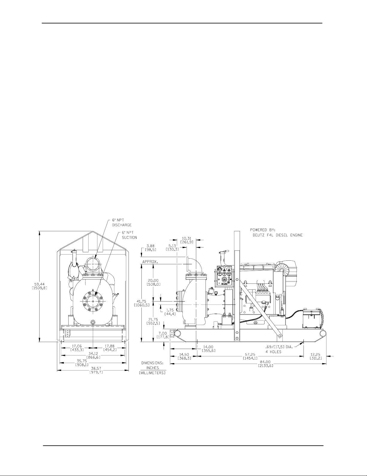
Pump Dimensions
SeeFigure1fortheapproximatephysicaldimensionsofthispump.
Figure 1. Pump Model 86A2--- F4L
PREINSTALLATION INSPECTION
The pump assembly was inspected and tested before shipment from the factory. Before installation,
inspect the pump for damage which may have oc curred during shipment. Check as follows:
a. Inspect the pump and engine for cracks,
dents, damaged threads, and other obvious
damage.
b. Check for and tighten loose attaching hard-
ware. Since gaskets tend to shrink after dry-
PAGE B -- 1INSTALLATION
OM--00957 80 SERIES
ing, check for loose hardware at mating surfaces.
c. Carefully read all tags, decals, and markings
on the pump assembly, and perform all duties
indicated.
d. Check levels and lubricate as necessary. Re-
fer to LUBRICATION in the MAINTENANCE
AND REPAIR section of this manual and perform duties as instructed.
e. If the pump end has been stored for more than
12 months, some of the components or lubricants may have exceeded their maximum
shelf life. These must be inspected or re-
placed to ensure maximum pump service.
If the maximum shelf life has been exceeded, or if
anything appears to be abnormal, contact your
Gorman-Rupp distributor or the factory to determine the repair or updating policy. Do not put the
pump into service until appropriate action has
been tak en.
POSITIONING PUMP
Use lifting and moving equipment in
good repair and with adequate capacity
to prevent injuries to personnel or damage to equipment. Suction and discharge hoses and piping must be removed from the pump before lifting.
Lifting
Use lifting equipment with a capacity of at least
10,400 pounds (4717 kg). This pump weighs approximately 2,074 pounds (941 kg), not including
the weight of accessories or engine or any optional
equipment. Customer installed equipment such as
suction and discharge piping must be removed
before attempting to lift.
Battery Specifications And Installation
Unless otherw ise specified on the pump order, the
engine battery wa s not included with the unit. Refer to the following specifications when selecting a
battery.
Table 1. Battery Specifications
Cold Reserve Approx.
Crank Capacity Amp/ Overall
Voltage
12 Volts 960-975 365 175 8.75W
Amps @80˚FHr. Dims.
@0˚F (Minutes) Rating (Inches)
20.5L
x
x
9.75H
Refer to the information accompanying the battery
and/or electrolyte solution for activation and charging instructions.
Before installing the battery, clean the positive and
negative cable connectors, and the battery terminals. Secure the battery by tightening the
holddown brackets. The terminals and clamps
may be coated with petroleum jelly to retard corrosion. Connect and tighten the positive cable first,
then the negative cable.
Thepumpassemblycanbeseriously
damaged if the cables or chains used to lift
and move the unit are improperly wrapped
around the pump.
Mounting
Locate the pump in an accessible place as close as
practical to the liquid being pumped. Level mounting is essential for proper operation.
The pump may have to be supported or shimmed
to provide for level operation or to eliminate vibration.
If the pump has been mounted on a moveable
base, make certain the base is stationary by setting
the brake and blocking the wheels before attempting to operate the pump.
To ensure sufficient lubrication and fuel s upply to
the engine, do not position the pump and engine
more than 15_ off horizontal for continuous operation. The pump and engine may be positioned up
to 30_ off horizontal for intermittent operation
only; however, the engine manufacturer should be
consulted for continuous operation at angles
greater than 15_.
PAGE B -- 2 INSTALLATION

80 SERIES OM--00957
SUCTION AND DISCHARGE PIPING
Materials
Either pipe or hose maybe used for suction and
discharge lines; however, the materials must be
compatible with the liquid being pumped. If hose is
used in suction lines, it must be the rigid-wall, reinforced type to prevent collapse under suction. Using piping couplings in suction lines is not recommended.
Line Configuration
Keep suction and discharge lines as straight as
possible to minimize friction losses. Make minimum use of elbows and fittings, w hich substantially increase friction loss. If elbows are necessary,
use the long-radius type to minimize friction loss.
SUCTION LINES
To avoid air pockets which could affect pump priming, the s uction line must be as short and direct as
possible. When operation involves a suction lift, the
line must always slope upward to the pump from
the source of the liquid being pumped; if the line
slopes down to the pump at any point along the
suction run, air pockets will be created.
Fittings
Suction lines should be the same size as the pump
inlet. If reducers are used in suction lines, they
should be the eccentric type, and should be installed with the flat part of the reducers uppermost
to avoid creating air pockets. Valves are not normally used in suction lines, but if a valve is used,
install it with the stem horizontal to avoid air pockets.
This pump is designed to handle up to 1-15/16 inch
(49,21 mm) diameter spherical solids.
Connections to Pump
Before tightening a connecting flange, align it exactly with the pump port. Never pull a pipe line into
place by tightening the flange bolts and/or couplings.
Lines near the pump must be independently supported to avoid strain on the pump which could
cause excessive vibration, decreased bearing life,
and increased shaft and seal wear. If hose-type
lines are used, they should have adequate support
to secure them when filled with liquid a nd under
pressure.
Gauges
Most pumps are drilled and tapped for installing
discharge pressure and vacuum suction gauges. If
these gauges are desired for pumps that a re not
tapped, drill and tap the suction and discharge
lines not less than 18 inches (457 mm) from the
suction and discharge ports and install the lines.
Installation closer to the pump may result in erratic
readings.
Sealing
Since even a slight leak will affect priming, head,
and capacity, especially when operating with a
high suction lift, all connections in the suction line
should be sealed with pipe dope to ensure an airtight seal. Follow the sealant manufacturer’s recommendations when selecting and applying the
pipe dope. The pipe dope should be compatible
with the liquid being pumped.
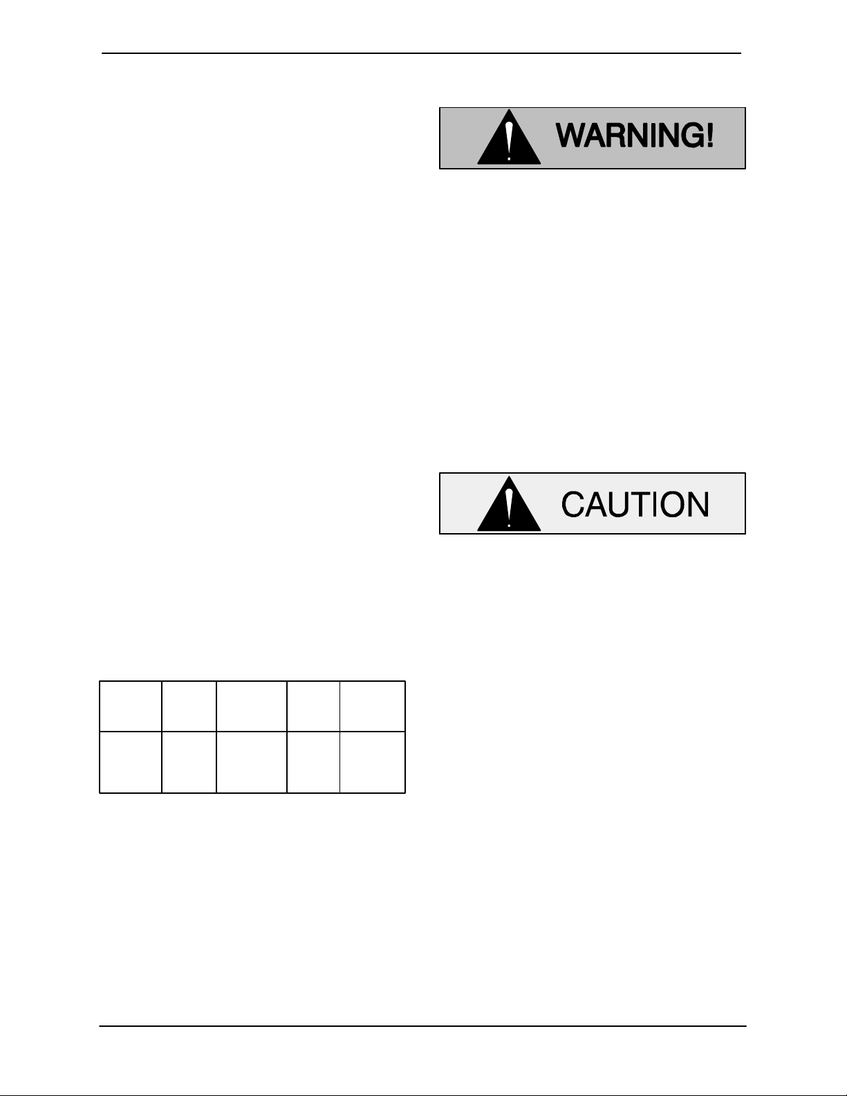
Suction Line Positioning
The depth of submergence of the suction line is
critical to efficient pump operation. Figure 2 shows
recommended minimum submergence vs. veloc-
ity.
NOTE
The pipe submergence required may be reduced
by installing a standard pipe increaser fitting at the
end of the suction line. The larger opening size will
reduce the inlet velocity. Calculate the required
submergence using the following formula based
on the increased opening size (area or diameter).
PAGE B -- 3INSTALLATION
OM--00957 80 SERIES
Figure 2. Recommended Minimum Suction Line Submergence vs. Velocity
FLOAT SWITCHES
Installation
The standard pump is not furnished with a means
to automatically regulate liquid level. However, if
the unit is equipped with the optional auto-start
control system, the pump can be conformed to
start and stop as the liquid level in the wet well or
sump rises and falls. The autostart option employs
either a single or double float switch system, where
a bulb raises or lowers (floats) with the liquid level,
thus activating an enclosed miniature switch. The
floats are equipped with a socket type connector
that plugs into a matching receptacle on the auto start control box.
Standard floats are equipped with 50 feet (15,2 m)
of cable.
When installing the floats, note the following:
a. Be sure to provide sufficient room in the wet
well or sump so that floats do not get obstructed or drawn into the suction line. If a flexible suction hose is used, it may be extended
to lay along the bottom of the wet w ell or sump
and the float can be attached to the hose
above the point where it bends along the bottom. Direct the suction line toward the flow,
and the float(s) away from the flow. If a standpipe is available, attach the float switch cable
to the standpipe in the sump at the approximatedesiredliquidlevel.
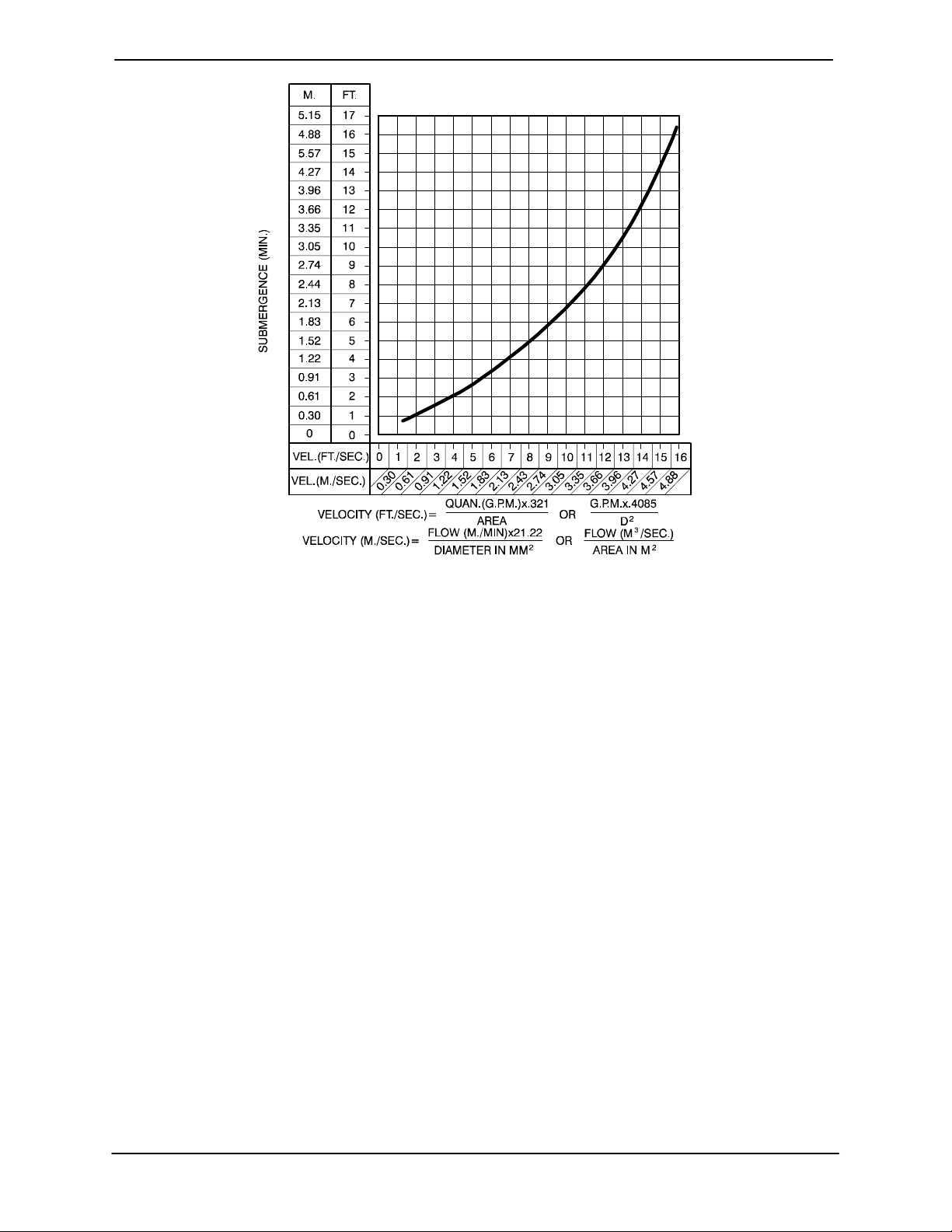
b. In a single float system, the cable can be teth-
ered to the suction line or standpipe approximately 6 inches (152 mm) above the float.
This setting allows approximately 9 inches
(229 mm) of liquid rise betw een pump start/
stop. The start/stop interval may be increased
by extending the float end of the cable. The
liquid level in the sump will increase approximately 8 inches (203 mm) between start/stop
intervals for every 6 inches (152 mm) of cable
increase.
c. If a double float switch system is used, posi-
tion the “Start” float at the desired high water
level in the sump, and the “Stop” float at the
desired low water level in the pump.
d. Refer to Figure 3 for additional float switch
data.
PAGE B -- 4 INSTALLATION
80 SERIES OM--00957
ENGINE
CONTROL
BOX
ON
(Emptying)
OFF
(Filling)
OPERATING
CABLE
TETHER
RANGE
(See Table Below)
POINT
OFF
(Emptying)
1.25” Pipe
(Not Furnished)
ON
(Filling)
Figure 3. Float Switch Data
DISCHARGE LINES
Siphoning
Do not terminate the discharge line at a level lower
than that of the liquid being pumped unless a siphon breaker is used in the line. Otherwise, a siphoning action causing damage to the pump
could result.
Val ves
If a throttling valve is desired in the discharge line,
useavalveaslargeasthelargestpipetominimize
friction losses. Never install a throttling valve in a
suction line.
3.0
(0.9)
2.5
(.76)
2.0
(0.6)
1.5
(.46)
1.0
(0.3)
0.5
(.15)
1.0
(0.3)
APPROXIMATEFREECORDLENGTHINFT.(M)
2.0
(0.6)
3.0
(0.9)
4.0
(1.2)
If the application involves a high discharge
head, gradually close the discharge
throttling valve before stopping the pump.
Bypass Lines
If a system check valve is used due to high discharge head, it may be necessary to vent trapped
air from the top of the pump during the priming
process. This may be accomplished by installing a
bypass line from the top of the pump, back to the
source of liquid. The end of the bypass line must be
submerged.Thelinemustbelargeenoughtoprevent clogging, but not so large as to affect pump
discharge capacity.
With high discharge heads, it is recommended that
a throttling valve and a system check valve be installed in the discharge line to protect the pump
from excessive shock pressure and reverse rotation when it is stopped.
ALIGNMENT
The alignment of the pump and engine are critical
for trouble-free performance. See Section E , Se-
curing Intermediate And Drive Assembly To Engine in MAINTENANCE AND REPAIR,fordetails.
PAGE B -- 5INSTALLATION
 Loading...