

GORMAN-RUPP PUMPS 80 Series, 84A2-QSF2.8P FT4, 86A2-QSF2.8P FT4 Installation, Operation, And Maintenance Manual With Parts List
OM-06752-01
March 23, 2015
INSTALLATION, OPERATION,
AND MAINTENANCE MANUAL
WITH PARTS LIST
80 SERIES PUMP
MODEL
84A2-QSF2.8P FT4
GORMAN‐RUPP PUMPS
www.grpumps.com
e2015 Gorman‐Rupp Pumps Printed in U.S.A.

Register your new
Gorman‐Rupp pump online at
www.grpumps.com
Valid serial number and e‐mail address required.
The engine exhaust from this
product contains chemicals
known to the State of California to
cause cancer, birth defects or
other reproductive harm.
RECORD YOUR PUMP MODEL AND SERIAL NUMBER
Please record your pump model and serial number in the
spaces provided below. Your Gorman‐Rupp distributor
needs this information when you require parts or service.
Pump Model:
Serial Number:

TABLE OF CONTENTS
INTRODUCTION PAGE I - 1.................................................
SAFETY ‐ SECTION A PAGE A - 1............................................
INSTALLATION - SECTION B PAGE B - 1....................................
Pump Dimensions PAGE B - 1.....................................................
PREINSTALLATION INSPECTION PAGE B - 1............................................
Battery Specifications And Installation PAGE B - 2....................................
POSITIONING PUMP PAGE B - 2.......................................................
Lifting PAGE B - 2.................................................................
Mounting PAGE B - 2.............................................................
SUCTION AND DISCHARGE PIPING PAGE B - 3.........................................
Materials PAGE B - 3..............................................................
Line Configuration PAGE B - 3......................................................
Connections to Pump PAGE B - 3..................................................
Gauges PAGE B - 3...............................................................
SUCTION LINES PAGE B - 3...........................................................
Fittings PAGE B - 3...............................................................
Sealing PAGE B - 3...............................................................
Suction Line Positioning PAGE B - 3................................................
DISCHARGE LINES PAGE B - 5........................................................
Siphoning PAGE B - 5.............................................................
Valves PAGE B - 5................................................................
Bypass Lines PAGE B - 5..........................................................
ALIGNMENT PAGE B - 5..............................................................
OPERATION - SECTION C PAGE C - 1......................................
PRIMING PAGE C - 1.................................................................
STARTING PAGE C - 2................................................................
Starting PAGE C - 2...............................................................
OPERATION PAGE C - 2..............................................................
Lines With a Bypass PAGE C - 2....................................................
Lines Without a Bypass PAGE C - 2.................................................
Leakage PAGE C - 3..............................................................
Liquid Temperature And Overheating PAGE C - 3.....................................
Strainer Check PAGE C - 3.........................................................
Pump Vacuum Check PAGE C - 3..................................................
STOPPING PAGE C - 3................................................................
Stopping PAGE C - 3..............................................................
Safety Shutdown System PAGE C - 4...............................................
OPERATION IN EXTREME HEAT PAGE C - 4............................................
BEARING TEMPERATURE CHECK PAGE C - 4..........................................
Cold Weather Preservation PAGE C - 5..............................................
TROUBLESHOOTING - SECTION D PAGE D - 1..............................
PREVENTIVE MAINTENANCE PAGE D - 3...............................................
i

TABLE OF CONTENTS
(continued)
PUMP MAINTENANCE AND REPAIR ‐ SECTION E PAGE E - 1.................
STANDARD PERFORMANCE CURVE PAGE E - 1........................................
PARTS LISTS:
Pump Model PAGE E - 3..........................................................
Pump End Assembly PAGE E - 5...................................................
Drive Assembly PAGE E - 6........................................................
PUMP AND SEAL DISASSEMBLY AND REASSEMBLY PAGE E - 7.........................
Suction Check Valve Removal PAGE E - 7...........................................
Separating Pump And Intermediate From Engine PAGE E - 7..........................
Loosening Impeller PAGE E - 8.....................................................
Pump Casing and Wear Plate Removal PAGE E - 8...................................
Impeller Removal PAGE E - 9......................................................
Seal Removal PAGE E - 9..........................................................
Shaft and Bearing Removal and Disassembly PAGE E - 9.............................
Shaft and Bearing Reassembly and Installation PAGE E - 10............................
Seal Reassembly and Installation PAGE E - 11........................................
Impeller Installation PAGE E - 13.....................................................
Securing Intermediate And Drive Assembly To Engine PAGE E - 13......................
Pump Casing and Wear Plate Installation PAGE E - 14.................................
Suction Check Valve Installation PAGE E - 14.........................................
Final Pump Reassembly PAGE E - 14................................................
LUBRICATION PAGE E - 15.............................................................
Seal Assembly PAGE E - 15.........................................................
Bearings PAGE E - 15..............................................................
Engine PAGE E - 15................................................................
ii

80 SERIES
OM-06752
INTRODUCTION
Thank You for purchasing a Gorman‐Rupp pump.
Read this manual carefully to learn how to safely
install and operate your pump. Failure to do so
could result in personal injury or damage to the
pump.
Because pump installations are seldom identical,
this manual cannot possibly provide detailed in
structions and precautions for every aspect of
each specific application. Therefore, it is the re
sponsibility of the owner/installer of the pump to
ensure that applications not addressed in this
manual are performed only after establishing that
neither operator safety nor pump integrity are com
promised by the installation. Pumps and related
equipment must be installed and operated ac
cording to all national, local and industry stan
dards.
If there are any questions regarding the pump or
its application which are not covered in this man
ual or in other literature accompanying this unit,
please contact your Gorman‐Rupp distributor, or
The Gorman‐Rupp Company:
HAZARD AND INSTRUCTION
DEFINITIONS
The following are used to alert maintenance per
sonnel to procedures which require special atten
tion, to those which could damage equipment, and
to those which could be dangerous to personnel:
Immediate hazards which WILL result in
severe personal injury or death. These
instructions describe the procedure re
quired and the injury which will result
from failure to follow the procedure.
Hazards or unsafe practices which
COULD result in severe personal injury
or death. These instructions describe
the procedure required and the injury
which could result from failure to follow
the procedure.
The Gorman‐Rupp Company
P.O. Box 1217
Mansfield, Ohio 44901-1217
Phone: (419) 755-1011
or:
Gorman‐Rupp of Canada Limited
70 Burwell Road
St. Thomas, Ontario N5P 3R7
Phone: (519) 631-2870
For information or technical assistance on the
power source, contact the power source manufac
turer's local dealer or representative.
Hazards or unsafe practices which COULD
result in minor personal injury or product
or property damage. These instructions
describe the requirements and the possi
ble damage which could result from failure
to follow the procedure.
NOTE
Instructions to aid in installation, operation, and
maintenance or which clarify a procedure.
PAGE I - 1INTRODUCTION
80 SERIES
OM-06752
SAFETY - SECTION A
This information applies to 80 Series en
gine driven pumps. Refer to the manual
accompanying the engine before at
tempting to begin operation.
Because pump installations are seldom
identical, this manual cannot possibly
provide detailed instructions and pre
cautions for each specific application.
Therefore, it is the owner/installer's re
sponsibility to ensure that applications
not addressed in this manual are per
formed only after establishing that nei
ther operator safety nor pump integrity
are compromised by the installation.
Before attempting to open or service the
pump:
1. Familiarize yourself with this man
ual.
2. Switch off the engine ignition and
disconnect the positive battery
cable to ensure that the pump will
remain inoperative.
3. Allow the pump to completely cool
if overheated.
4. Check the temperature before
opening any covers, plates, or
plugs.
5. Close the suction and discharge
valves.
6. Vent the pump slowly and cau
tiously.
7. Drain the pump.
This pump is designed to handle most
non‐volatile, non‐flammable liquids
containing specified entrained solids.
Do not attempt to pump volatile, corro
sive, or flammable materials, or any liq
uids which may damage the pump or en
danger personnel as a result of pump
failure.
Death or serious personal injury and
damage to the pump or components
can occur if proper lifting procedures
are not observed. Make certain that
hoists, chains, slings or cables are in
good working condition and of suffi
cient capacity and that they are posi
tioned so that loads will be balanced
and the pump or components will not be
damaged when lifting. Suction and dis
charge hoses and piping must be re
moved from the pump before lifting. Lift
the pump or component only as high as
necessary and keep personnel away
from suspended objects.
After the pump has been positioned,
make certain that the pump and all pip
ing or hose connections are tight, prop
erly supported and secure before oper
ation.
Do not operate the pump against a
closed discharge valve for long periods
of time. If operated against a closed dis
charge valve, pump components will
deteriorate, and the liquid could come
to a boil, build pressure, and cause the
pump casing to rupture or explode.
Do not remove plates, covers, gauges,
pipe plugs, or fittings from an over
PAGE A - 1SAFETY
heated pump. Vapor pressure within the
pump can cause parts being disen
gaged to be ejected with great force. Al
low the pump to completely cool before
servicing.
Do not operate an internal combustion
engine in an explosive atmosphere.
When operating internal combustion
engines in an enclosed area, make cer
tain that exhaust fumes are piped to the
outside. These fumes contain carbon
monoxide, a deadly gas that is color
less, tasteless, and odorless.
80 SERIESOM-06752
Allow an over‐heated pump to com
pletely cool before servicing. Do not re
move plates, covers, gauges, or fittings
from an over‐heated pump. Liquid with
in the pump can reach boiling tempera
tures, and vapor pressure within the
pump can cause parts being disen
gaged to be ejected with great force. Af
ter the pump completely cools, drain the
liquid from the pump by removing the
casing drain plug. Use caution when re
moving the plug to prevent injury to per
sonnel from hot liquid.
Never tamper with the governor to gain
more power. The governor establishes
safe operating limits that should not be
exceeded. The maximum continuous
operating speed for this pump is 2100
RPM.
Pumps and related equipment must be in
stalled and operated according to all na
tional, local and industry standards.
Fuel used by internal combustion en
gines presents an extreme explosion
and fire hazard. Make certain that all
fuel lines are securely connected and
free of leaks. Never refuel a hot or run
ning engine. Avoid overfilling the fuel
tank. Always use the correct type of fuel.
PAGE A - 2 SAFETY
80 SERIES OM-06752
INSTALLATION - SECTION B
Review all SAFETY information in Section A.
Since pump installations are seldom identical, this
section offers only general recommendations and
practices required to inspect, position, and ar
range the pump and piping.
Most of the information pertains to a standard
static lift application where the pump is positioned
above the free level of liquid to be pumped.
If installed in a flooded suction application where
the liquid is supplied to the pump under pressure,
some of the information such as mounting, line
configuration, and priming must be tailored to the
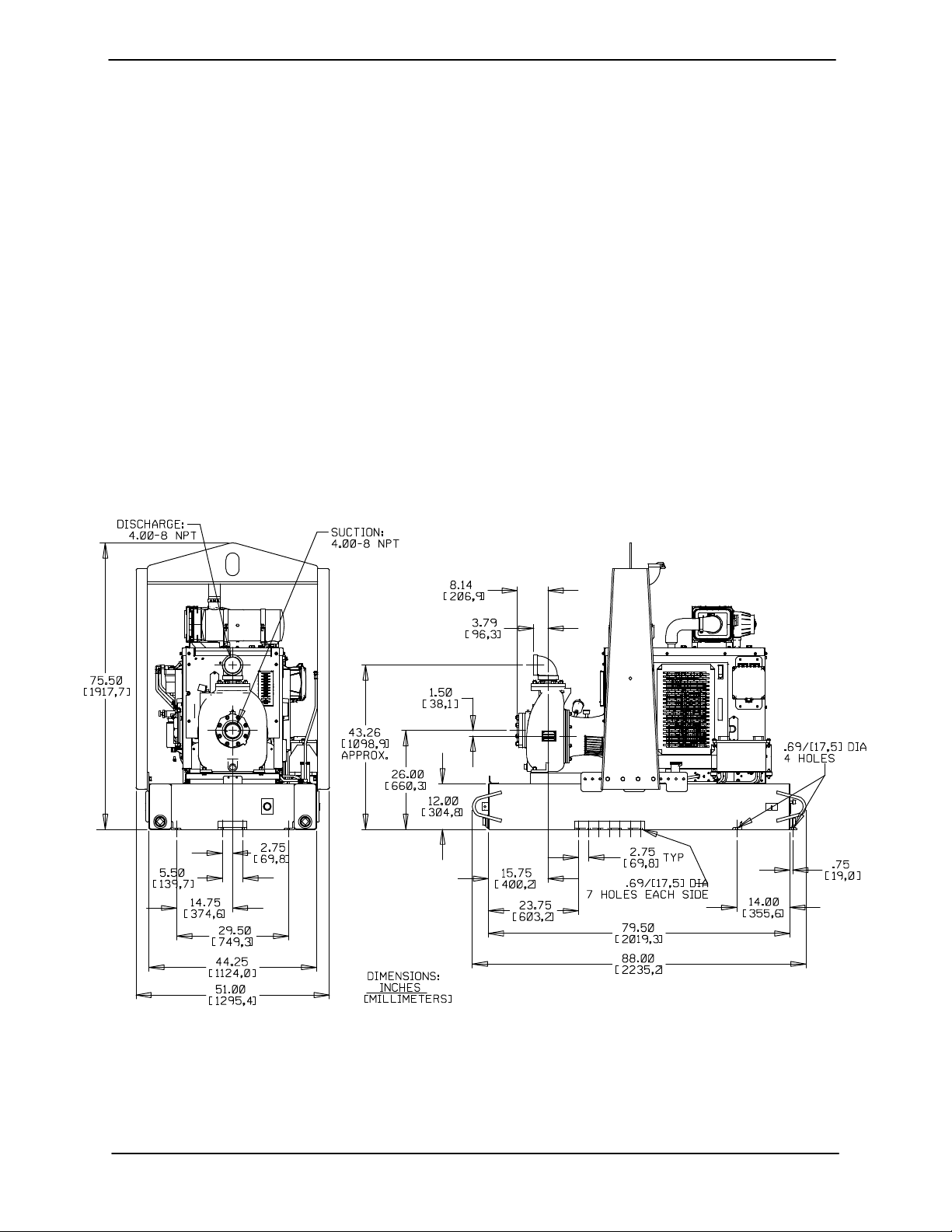
OUTLINE DRAWING
specific application. Since the pressure supplied
to the pump is critical to performance and safety,
be sure to limit the incoming pressure to 50% of the
maximum permissible operating pressure. If the
pump is fitted with a Gorman‐Rupp double grease
lubricated seal, the maximum incoming pressure
must be reduced to 10 p.s.i.
For further assistance, contact your Gorman‐Rupp
distributor or the Gorman‐Rupp Company.
Pump Dimensions
See Figure 1 for the approximate physical dimen
sions of this pump.
Figure 1. Pump Model 84A2-QSF2.8P FT4
PAGE B - 1INSTALLATION
OM-06752 80 SERIES
PREINSTALLATION INSPECTION
The pump assembly was inspected and tested be
fore shipment from the factory. Before installation,
inspect the pump for damage which may have oc
curred during shipment. Check as follows:
a. Inspect the pump and engine for cracks,
dents, damaged threads, and other obvious
damage.
b. Check for and tighten loose attaching hard
ware. Since gaskets tend to shrink after dry
ing, check for loose hardware at mating sur
faces.
c. Carefully read all tags, decals, and markings
on the pump assembly, and perform all duties
indicated.
Table 1. Battery Specifications
Cold Reserve Approx.
Crank Capacity Amp/ Overall
Voltage
12 Volts 960‐975 365 175 8.75W
Refer to the information accompanying the battery
and/or electrolyte solution for activation and charg
ing instructions.
Before installing the battery, clean the positive and
negative cable connectors, and the battery termi
nals. Secure the battery by tightening the
holddown brackets. The terminals and clamps
may be coated with petroleum jelly to retard corro
sion. Connect and tighten the positive cable first,
then the negative cable.
Amps @80°F Hr. Dims.
@ 0°F (Minutes) Rating (Inches)
20.5L
x
x
9.75H
POSITIONING PUMP
d. Check levels and lubricate as necessary. Re
fer to LUBRICATION in the MAINTENANCE
AND REPAIR section of this manual and per
form duties as instructed.
e. If the pump end has been stored for more than
12 months, some of the components or lubri
cants may have exceeded their maximum
shelf life. These must be inspected or re
placed to ensure maximum pump service.
If the maximum shelf life has been exceeded, or if
anything appears to be abnormal, contact your
Gorman‐Rupp distributor or the factory to deter
mine the repair or updating policy. Do not put the
pump into service until appropriate action has
been taken.
Battery Specifications And Installation
Unless otherwise specified on the pump order, the
engine battery was not included with the unit. Re
fer to the following specifications when selecting a
battery.
Death or serious personal injury and
damage to the pump or components
can occur if proper lifting procedures
are not observed. Make certain that
hoists, chains, slings or cables are in
good working condition and of suffi
cient capacity and that they are posi
tioned so that loads will be balanced
and the pump or components will not be
damaged when lifting. Suction and dis
charge hoses and piping must be re
moved from the pump before lifting. Lift
the pump or component only as high as
necessary and keep personnel away
from suspended objects.
Lifting
Pump unit weights will vary depending on the
mounting and drive provided. Check the shipping
tag on the unit packaging for the actual weight, and
use lifting equipment with appropriate capacity.
Drain the pump and remove all customer‐installed
equipment such as suction and discharge hoses
or piping before attempting to lift existing, installed
units.
PAGE B - 2 INSTALLATION

80 SERIES OM-06752
Mounting
Locate the pump in an accessible place as close as
practical to the liquid being pumped. Level mount
ing is essential for proper operation.
The pump may have to be supported or shimmed
to provide for level operation or to eliminate vibra
tion.
If the pump has been mounted on a moveable
base, make certain the base is stationary by setting
the brake and blocking the wheels before attempt
ing to operate the pump.
To ensure sufficient lubrication and fuel supply to
the engine, do not position the pump and engine
more than 15
tion. The pump and engine may be positioned up
to 30_ off horizontal for intermittent operation
only; however, the engine manufacturer should be
consulted for continuous operation at angles
greater than 15_.
_
off horizontal for continuous opera
SUCTION AND DISCHARGE PIPING
Materials
Lines near the pump must be independently sup
ported to avoid strain on the pump which could
cause excessive vibration, decreased bearing life,
and increased shaft and seal wear. If hose‐type
lines are used, they should have adequate support
to secure them when filled with liquid and under
pressure.
Gauges
Most pumps are drilled and tapped for installing
discharge pressure and vacuum suction gauges. If
these gauges are desired for pumps that are not
tapped, drill and tap the suction and discharge
lines not less than 18 inches (457 mm) from the
suction and discharge ports and install the lines.
Installation closer to the pump may result in erratic
readings.
SUCTION LINES
To avoid air pockets which could affect pump prim
ing, the suction line must be as short and direct as
possible. When operation involves a suction lift, the
line must always slope upward to the pump from
the source of the liquid being pumped; if the line
slopes down to the pump at any point along the
suction run, air pockets will be created.
Either pipe or hose maybe used for suction and
discharge lines; however, the materials must be
compatible with the liquid being pumped. If hose is
used in suction lines, it must be the rigid‐wall, rein
forced type to prevent collapse under suction. Us
ing piping couplings in suction lines is not recom
mended.
Line Configuration
Keep suction and discharge lines as straight as
possible to minimize friction losses. Make mini
mum use of elbows and fittings, which substan
tially increase friction loss. If elbows are necessary,
use the long‐radius type to minimize friction loss.
Connections to Pump
Before tightening a connecting flange, align it ex
actly with the pump port. Never pull a pipe line into
place by tightening the flange bolts and/or cou
plings.
Fittings
Suction lines should be the same size as the pump
inlet. If reducers are used in suction lines, they
should be the eccentric type, and should be in
stalled with the flat part of the reducers uppermost
to avoid creating air pockets. Valves are not nor
mally used in suction lines, but if a valve is used,
install it with the stem horizontal to avoid air pock
ets.
Strainers
If a strainer is furnished with the pump, be certain
to use it; any spherical solids which pass through a
strainer furnished with the pump will also pass
through the pump itself.
If a strainer is not furnished with the pump, but is
installed by the pump user, make certain that the
total area of the openings in the strainer is at least
three or four times the cross section of the suction
line, and that the openings will not permit passage
PAGE B - 3INSTALLATION
OM-06752 80 SERIES
of solids larger than the solids handling capability
of the pump.
This pump is designed to handle up to 1‐1/8 inch
(28,6 mm) diameter spherical solids.
Sealing
Since even a slight leak will affect priming, head,
and capacity, especially when operating with a
high suction lift, all connections in the suction line
should be sealed with pipe dope to ensure an air
tight seal. Follow the sealant manufacturer's rec
ommendations when selecting and applying the
pipe dope. The pipe dope should be compatible
with the liquid being pumped.
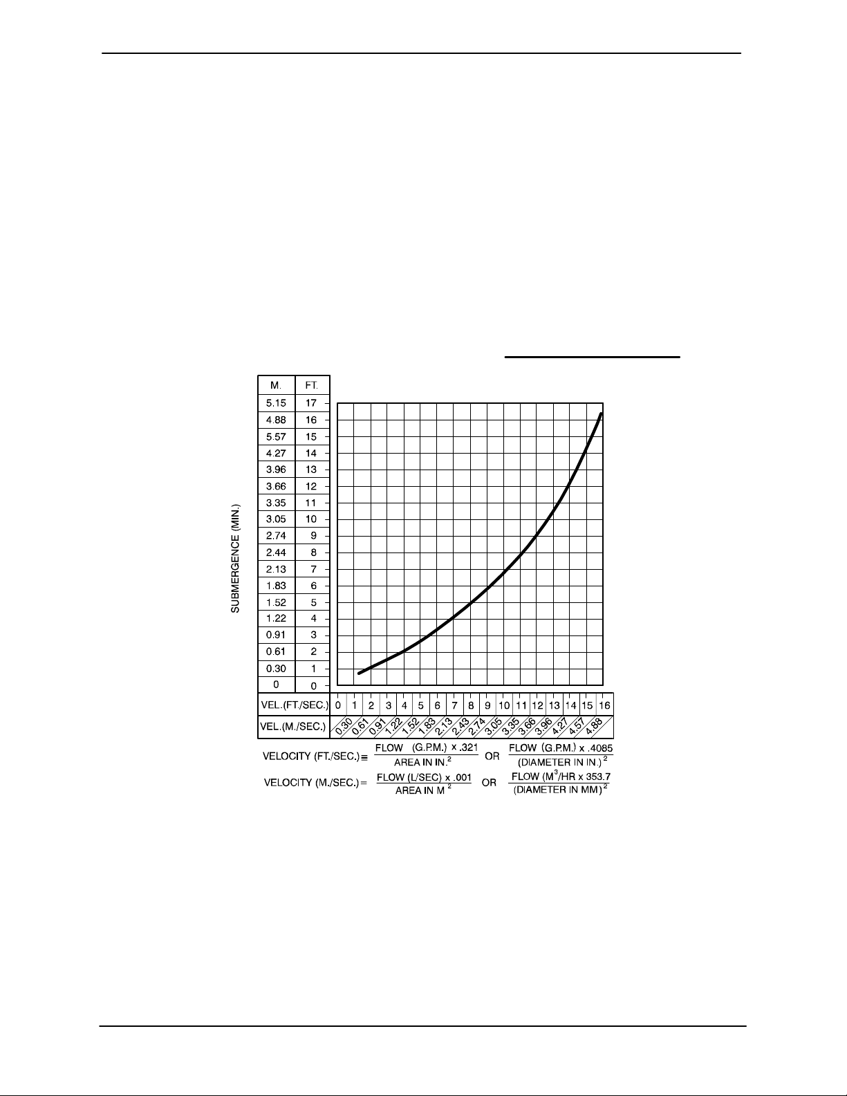
Suction Line Positioning
The depth of submergence of the suction line is
critical to efficient pump operation.
recommended minimum submergence vs. veloc
ity.
Figure 2 shows
NOTE
The pipe submergence required may be reduced
by installing a standard pipe increaser fitting at the
end of the suction line. The larger opening size will
reduce the inlet velocity. Calculate the required
submergence using the following formula based
on the increased opening size (area or diameter).
Figure 2. Recommended Minimum Suction Line Submergence vs. Velocity
DISCHARGE LINES
Siphoning
Do not terminate the discharge line at a level lower
than that of the liquid being pumped unless a si
phon breaker is used in the line. Otherwise, a si
phoning action causing damage to the pump
could result.
PAGE B - 4 INSTALLATION
Valves
If a throttling valve is desired in the discharge line,
use a valve as large as the largest pipe to minimize
friction losses. Never install a throttling valve in a
suction line.
With high discharge heads, it is recommended that
a throttling valve and a system check valve be in
stalled in the discharge line to protect the pump

80 SERIES OM-06752
from excessive shock pressure and reverse rota
tion when it is stopped.
If the application involves a high discharge
head, gradually close the discharge
throttling valve before stopping the pump.
Bypass Lines
If a system check valve is used due to high dis
charge head, it may be necessary to vent trapped
air from the top of the pump during the priming
process. This may be accomplished by installing a
bypass line from the top of the pump, back to the
source of liquid. The end of the bypass line must be
submerged. The line must be large enough to pre
vent clogging, but not so large as to affect pump
discharge capacity.
ALIGNMENT
The alignment of the pump and engine are critical
for trouble‐free performance. See Section E, Se
curing Intermediate And Drive Assembly To En
gine in MAINTENANCE AND REPAIR, for details.
PAGE B - 5INSTALLATION
 Loading...