

Gorman-Rupp Pumps 82D1-EX13-X User Manual
ABCEG
OM−06106−01
January 22, 2008
Rev. A 10-29-09
INSTALLATION, OPERATION,
AND MAINTENANCE MANUAL
WITH PARTS LIST
80 SERIES PUMP
MODEL
82D1−EX13−X
THE GORMAN-RUPP COMPANY D MANSFIELD, OHIO
www.grpumps.com
GORMAN-RUPP OF CANADA LIMITED D ST. THOMAS, ONTARIO, CANADA Printed in U.S.A.
E2008 The Gorman-Rupp Company

Register your new
Gorman-Rupp pump online at
www.grpumps.com
Valid serial number and e-mail address required.
The engine exhaust from this
product contains chemicals
known to the State of California to
cause cancer, birth defects or
other reproductive harm.
RECORD YOUR PUMP MODEL AND SERIAL NUMBER
Please record your pump model and serial number in the
spaces provided below. Your Gorman-Rupp distributor
needs this information when you require parts or service.
Pump Model:
Serial Number:

TABLE OF CONTENTS
INTRODUCTION PAGE I − 1. . . . . . . . . . . . . . . . . . . . . . . . . . . . . . . . . . . . . . . . . . . . . . . . .
SAFETY - SECTION A PAGE A − 1. . . . . . . . . . . . . . . . . . . . . . . . . . . . . . . . . . . . . . . . . . . .
INSTALLATION − SECTION B PAGE B − 1. . . . . . . . . . . . . . . . . . . . . . . . . . . . . . . . . . . .
Pump Dimensions PAGE B − 1. . . . . . . . . . . . . . . . . . . . . . . . . . . . . . . . . . . . . . . . . . . . . . . . . . . . .
PREINSTALLATION INSPECTION PAGE B − 1. . . . . . . . . . . . . . . . . . . . . . . . . . . . . . . . . . . . . . . . . . . .
POSITIONING PUMP PAGE B − 2. . . . . . . . . . . . . . . . . . . . . . . . . . . . . . . . . . . . . . . . . . . . . . . . . . . . . . .
Lifting PAGE B − 2. . . . . . . . . . . . . . . . . . . . . . . . . . . . . . . . . . . . . . . . . . . . . . . . . . . . . . . . . . . . . . . . .
Mounting PAGE B − 2. . . . . . . . . . . . . . . . . . . . . . . . . . . . . . . . . . . . . . . . . . . . . . . . . . . . . . . . . . . . .
SUCTION AND DISCHARGE PIPING PAGE B − 2. . . . . . . . . . . . . . . . . . . . . . . . . . . . . . . . . . . . . . . . .
Materials PAGE B − 2. . . . . . . . . . . . . . . . . . . . . . . . . . . . . . . . . . . . . . . . . . . . . . . . . . . . . . . . . . . . . .
Line Configuration PAGE B − 2. . . . . . . . . . . . . . . . . . . . . . . . . . . . . . . . . . . . . . . . . . . . . . . . . . . . . .
Connections to Pump PAGE B − 2. . . . . . . . . . . . . . . . . . . . . . . . . . . . . . . . . . . . . . . . . . . . . . . . . .
Gauges PAGE B − 3. . . . . . . . . . . . . . . . . . . . . . . . . . . . . . . . . . . . . . . . . . . . . . . . . . . . . . . . . . . . . . .
SUCTION LINES PAGE B − 3. . . . . . . . . . . . . . . . . . . . . . . . . . . . . . . . . . . . . . . . . . . . . . . . . . . . . . . . . . .
Fittings PAGE B − 3. . . . . . . . . . . . . . . . . . . . . . . . . . . . . . . . . . . . . . . . . . . . . . . . . . . . . . . . . . . . . . .
Strainers PAGE B − 3. . . . . . . . . . . . . . . . . . . . . . . . . . . . . . . . . . . . . . . . . . . . . . . . . . . . . . . . . . . . . .
Sealing PAGE B − 3. . . . . . . . . . . . . . . . . . . . . . . . . . . . . . . . . . . . . . . . . . . . . . . . . . . . . . . . . . . . . . .
Suction Lines In Sumps PAGE B − 3. . . . . . . . . . . . . . . . . . . . . . . . . . . . . . . . . . . . . . . . . . . . . . . . .
Suction Line Positioning PAGE B − 3. . . . . . . . . . . . . . . . . . . . . . . . . . . . . . . . . . . . . . . . . . . . . . . .
DISCHARGE LINES PAGE B − 4. . . . . . . . . . . . . . . . . . . . . . . . . . . . . . . . . . . . . . . . . . . . . . . . . . . . . . . .
Siphoning PAGE B − 4. . . . . . . . . . . . . . . . . . . . . . . . . . . . . . . . . . . . . . . . . . . . . . . . . . . . . . . . . . . . .
Valves PAGE B − 4. . . . . . . . . . . . . . . . . . . . . . . . . . . . . . . . . . . . . . . . . . . . . . . . . . . . . . . . . . . . . . . .
Bypass Lines PAGE B − 4. . . . . . . . . . . . . . . . . . . . . . . . . . . . . . . . . . . . . . . . . . . . . . . . . . . . . . . . . .
GROUNDING PAGE B − 5. . . . . . . . . . . . . . . . . . . . . . . . . . . . . . . . . . . . . . . . . . . . . . . . . . . . . . . . . . . . .
OPERATION − SECTION C PAGE C − 1. . . . . . . . . . . . . . . . . . . . . . . . . . . . . . . . . . . . . .
PRIMING PAGE C − 1. . . . . . . . . . . . . . . . . . . . . . . . . . . . . . . . . . . . . . . . . . . . . . . . . . . . . . . . . . . . . . . . .
STARTING PAGE C − 1. . . . . . . . . . . . . . . . . . . . . . . . . . . . . . . . . . . . . . . . . . . . . . . . . . . . . . . . . . . . . . . .
OPERATION PAGE C − 1. . . . . . . . . . . . . . . . . . . . . . . . . . . . . . . . . . . . . . . . . . . . . . . . . . . . . . . . . . . . . .
Lines With a Bypass PAGE C − 1. . . . . . . . . . . . . . . . . . . . . . . . . . . . . . . . . . . . . . . . . . . . . . . . . . . .
Lines Without a Bypass PAGE C − 2. . . . . . . . . . . . . . . . . . . . . . . . . . . . . . . . . . . . . . . . . . . . . . . . .
Leakage PAGE C − 2. . . . . . . . . . . . . . . . . . . . . . . . . . . . . . . . . . . . . . . . . . . . . . . . . . . . . . . . . . . . . .
Liquid Temperature And Overheating PAGE C − 2. . . . . . . . . . . . . . . . . . . . . . . . . . . . . . . . . . . . .
Strainer Check PAGE C − 2. . . . . . . . . . . . . . . . . . . . . . . . . . . . . . . . . . . . . . . . . . . . . . . . . . . . . . . . .
Pump Vacuum Check PAGE C − 2. . . . . . . . . . . . . . . . . . . . . . . . . . . . . . . . . . . . . . . . . . . . . . . . . .
STOPPING PAGE C − 2. . . . . . . . . . . . . . . . . . . . . . . . . . . . . . . . . . . . . . . . . . . . . . . . . . . . . . . . . . . . . . . .
Cold Weather Preservation PAGE C − 3. . . . . . . . . . . . . . . . . . . . . . . . . . . . . . . . . . . . . . . . . . . . . .
TROUBLESHOOTING − SECTION D PAGE D − 1. . . . . . . . . . . . . . . . . . . . . . . . . . . . . .
PREVENTIVE MAINTENANCE PAGE D − 3. . . . . . . . . . . . . . . . . . . . . . . . . . . . . . . . . . . . . . . . . . . . . . .
PUMP MAINTENANCE AND REPAIR - SECTION E PAGE E − 1. . . . . . . . . . . . . . . . .
STANDARD PERFORMANCE CURVE PAGE E − 1. . . . . . . . . . . . . . . . . . . . . . . . . . . . . . . . . . . . . . . .
i

TABLE OF CONTENTS
(continued)
PARTS LISTS:
Pump Model PAGE E − 3. . . . . . . . . . . . . . . . . . . . . . . . . . . . . . . . . . . . . . . . . . . . . . . . . . . . . . . . . .
Pump End Assy PAGE E − 5. . . . . . . . . . . . . . . . . . . . . . . . . . . . . . . . . . . . . . . . . . . . . . . . . . . . . . . .
Engine Modification Assembly PAGE E − 7. . . . . . . . . . . . . . . . . . . . . . . . . . . . . . . . . . . . . . . . . . .
PUMP AND SEAL DISASSEMBLY AND REASSEMBLY PAGE E − 8. . . . . . . . . . . . . . . . . . . . . . . . .
Suction Check Valve Disassembly PAGE E − 8. . . . . . . . . . . . . . . . . . . . . . . . . . . . . . . . . . . . . . . .
Pump Casing Removal PAGE E − 9. . . . . . . . . . . . . . . . . . . . . . . . . . . . . . . . . . . . . . . . . . . . . . . . .
Impeller Removal PAGE E − 9. . . . . . . . . . . . . . . . . . . . . . . . . . . . . . . . . . . . . . . . . . . . . . . . . . . . . .
Seal Removal and Disassembly PAGE E − 9. . . . . . . . . . . . . . . . . . . . . . . . . . . . . . . . . . . . . . . . . .
Seal Reassembly and Installation PAGE E − 9. . . . . . . . . . . . . . . . . . . . . . . . . . . . . . . . . . . . . . . .
Impeller Installation And Adjustment PAGE E − 11. . . . . . . . . . . . . . . . . . . . . . . . . . . . . . . . . . . . . .
Pump Casing Installation PAGE E − 11. . . . . . . . . . . . . . . . . . . . . . . . . . . . . . . . . . . . . . . . . . . . . . . .
Suction Check Valve Installation PAGE E − 11. . . . . . . . . . . . . . . . . . . . . . . . . . . . . . . . . . . . . . . . .
Final Pump Assembly PAGE E − 11. . . . . . . . . . . . . . . . . . . . . . . . . . . . . . . . . . . . . . . . . . . . . . . . . .
LUBRICATION PAGE E − 12. . . . . . . . . . . . . . . . . . . . . . . . . . . . . . . . . . . . . . . . . . . . . . . . . . . . . . . . . . . . .
Seal Assembly PAGE E − 12. . . . . . . . . . . . . . . . . . . . . . . . . . . . . . . . . . . . . . . . . . . . . . . . . . . . . . . . .
Engine PAGE E − 12. . . . . . . . . . . . . . . . . . . . . . . . . . . . . . . . . . . . . . . . . . . . . . . . . . . . . . . . . . . . . . . .
ENGINE MODIFICATIONS PAGE E − 12. . . . . . . . . . . . . . . . . . . . . . . . . . . . . . . . . . . . . . . . . . . . . . . . . .
ii
80 SERIES
OM−06106
INTRODUCTION
Thank You for purchasing a Gorman-Rupp pump.
Read this manual carefully to learn how to safely
install and operate your pump. Failure to do so
could result in personal injury or damage to the
pump.
This manual will alert personnel to known procedures which require special attention, to those
which could damage equipment, and to those
which could be dangerous to personnel. However,
this manual cannot possibly anticipate and provide
detailed precautions for every situation that might
occur during maintenance of the unit. Therefore, it
is the responsibility of the owner/maintenance personnel to ensure that only safe, established main-
tenance procedures are used, and that any procedures not addressed in this manual are performed
only after establishing that neither personal safety
nor pump integrity are compromised by such practices.
This pump is a 80 Series, semi-open impeller, selfpriming centrifugal model with a suction check
valve. It is close-coupled to a single cylinder Robin
gasoline engine incorporating such safety features
as splash guards, grounding wire and shielded
spark plug.
The pump is designed for pumping water, gasoline
or other petroleum products in a non-flammable atmosphere. The basic material of construction aluminum, with an aluminum impeller and steel wearing parts.
The following are used to alert maintenance personnel to procedures which require special attention, to those which could damage equipment, and
to those which could be dangerous to personnel:
Immediate hazards which WILL result in
severe personal injury or death. These
instructions describe the procedure required and the injury which will result
from failure to follow the procedure.
Hazards or unsafe practices which
COULD result in severe personal injury
or death. These instructions describe
the procedure required and the injury
which could result from failure to follow
the procedure.
If there are any questions regarding the pump or
its application which are not covered in this manual or in other literature accompanying this unit,
please contact your Gorman-Rupp distributor, or:
The Gorman-Rupp Company
P.O. Box 1217
Mansfield, Ohio 44901−1217
Phone: (419) 755−1011
or:
Gorman-Rupp of Canada Limited
70 Burwell Road
St. Thomas, Ontario N5P 3R7
Phone: (519) 631−2870
Hazards or unsafe practices which COULD
result in minor personal injury or product
or property damage. These instructions
describe the requirements and the possible damage which could result from failure
to follow the procedure.
NOTE
Instructions to aid in installation, operation,and
maintenance, or which clarify a procedure.
PAGE I − 1INTRODUCTION
80 SERIES
OM−06106
SAFETY - SECTION A
This information applies to 80 Series engine driven pumps. Refer to the manual
accompanying the engine before attempting to begin operation.
This manual will alert personnel to
known procedures which require special attention, to those which could
damage equipment, and to those which
could be dangerous to personnel. However, this manual cannot possibly anticipate and provide detailed instructions
and precautions for every situation that
might occur during maintenance of the
unit. Therefore, it is the responsibility of
the owner/maintenance personnel to
ensure that only safe, established maintenance procedures are used, and that
any procedures not addressed in this
manual are performed only after establishing that neither personal safety nor
pump integrity are compromised by
such practices.
The engine used in this pump is not
standard. It has been modified for use in
handling gasoline and other petroleum
products in a well-ventilated, non-flammable atmosphere free of combustible
hazards. It cannot be further modified
without affecting performance and safety factors. The shield and spark arresting modifications must be inspected
and maintained regularly while the unit
is in use. Refer to the manual accompanying the engine before attempting to
start the engine.
This pump is designed to handle water,
gasoline and other petroleum products
in a non-flammable atmosphere. Do not
attempt to pump corrosive materials, or
any liquids which may damage the
pump or endanger personnel as a result
of pump failure.
Before attempting to open or service the
pump:
1. Familiarize yourself with this manual.
2. Shut down the engine and disconnect the spark plug wire to ensure
that the pump will remain inoperative.
3. Allow the pump to completely cool
if overheated.
4. Check the temperature before
opening any covers, plates, or
plugs.
5. Close the suction and discharge
valves.
6. Vent the pump slowly and cautiously.
7. Drain the pump.
After the pump has been installed, make
certain that the pump and all piping or
hose connections are tight, properly
supported and secure before operation.
Do not operate the pump against a
closed discharge valve for long periods
of time. If operated against a closed discharge valve, pump components will
deteriorate, and the liquid could come
to a boil, build pressure, and cause the
pump casing to rupture or explode.
PAGE A − 1SAFETY
Do not remove plates, covers, gauges,
pipe plugs, or fittings from an overheated pump. Vapor pressure within the
pump can cause parts being disengaged to be ejected with great force. allow the pump to cool before servicing.
Overheated pumps can cause severe
burns and injuries. If overheating of the
pump occurs:
1. Stop the pump immediately.
2. Ventilate the area.
3. Allow the pump to completely cool.
4. Check the temperature before
opening any covers, plates,
gauges, or plugs.
5. Vent the pump slowly and cautiously.
6. Refer to instructions in this manual
before restarting the pump.
80 SERIESOM−06106
outside. These fumes contain carbon
monoxide, a deadly gas that is colorless, tasteless, and odorless.
Fuel used by internal combustion engines presents an extreme explosion
and fire hazard. Make certain that all
fuel lines are securely connected and
free of leaks. Never refuel a hot or running engine. Avoid overfilling the fuel
tank. always use the correct type of fuel.
If this pump is used with volatile and/or
flammable liquids, be certain proper
safety practices are followed before operating or servicing the pump. Provide
adequate ventilation, prohibit smoking,
wear static-resistant clothing and
shoes. Clean up all fuel spills immediately after occurrence.
Never tamper with the governor to gain
Do not operate an internal combustion
engine in an explosive atmosphere.
When operating internal combustion
engines in an enclosed area, make certain that exhaust fumes are piped to the
PAGE A − 2 SAFETY
more power. The governor establishes
safe operating limits that should not be
exceeded. The maximum continuous
operating speed for this pump is 3800
RPM.
80 SERIES OM−06106
INSTALLATION − SECTION B
Review all SAFETY information in Section A.
Since pump installations are seldom identical, this
section offers only general recommendations and
practices required to inspect, position, and arrange the pump and piping.
Most of the information pertains to a standard
static lift application where the pump is positioned
above the free level of liquid to be pumped.
If installed in a flooded suction application where
the liquid is supplied to the pump under pressure,
some of the information such as mounting, line
configuration, and priming must be tailored to the
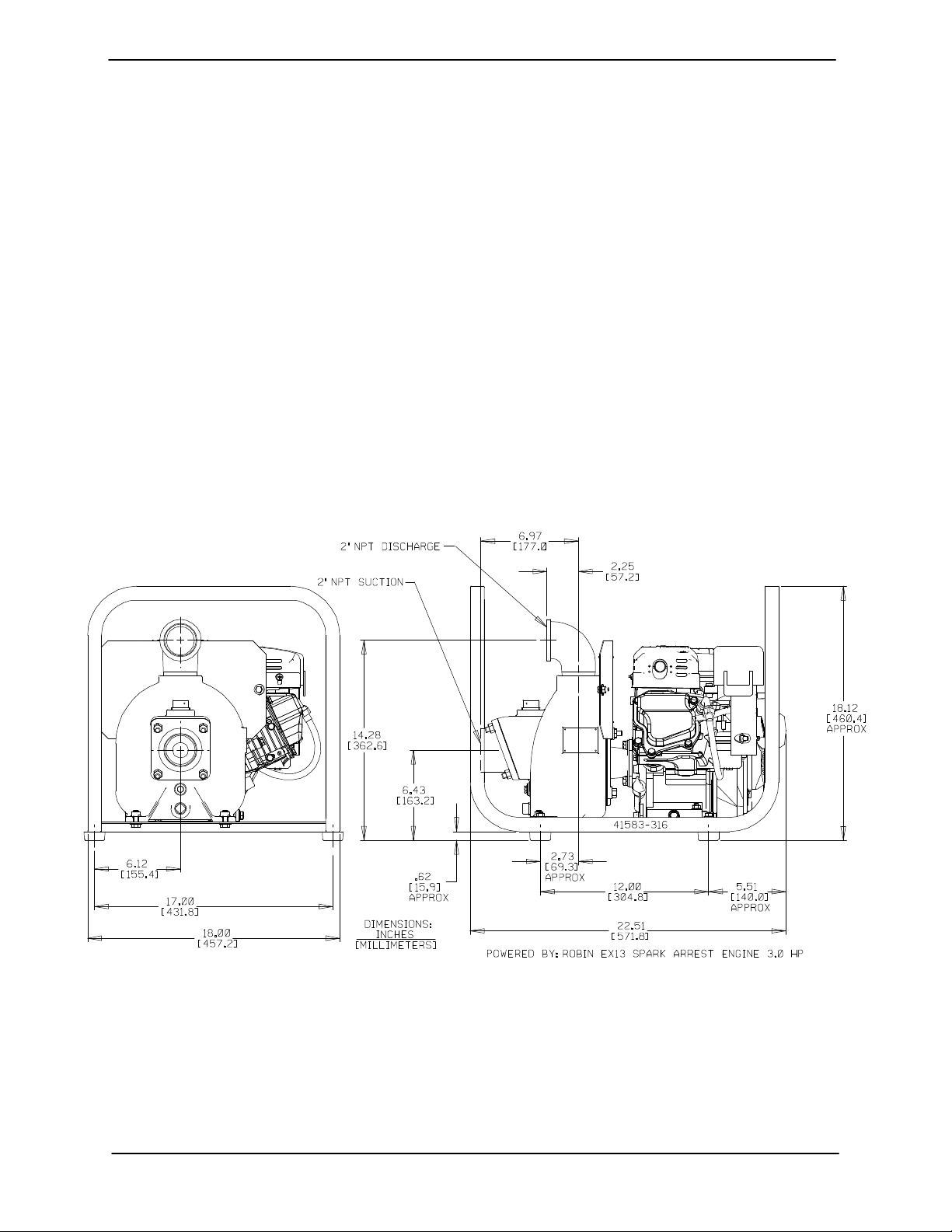
OUTLINE DRAWING
specific application. Since the pressure supplied
to the pump is critical to performance and safety,
be sure to limit the incoming pressure to 50% of the
maximum permissible operating pressure as
shown on the pump performance curve.
For further assistance, contact your Gorman-Rupp
distributor or the Gorman-Rupp Company.
Pump Dimensions
See Figure 1 for the approximate physical dimen-
sions of this pump.
Figure 1. Pump Model 82D1-EX13−X
PREINSTALLATION INSPECTION
The pump assembly was inspected and tested before shipment from the factory. Before installation,
inspect the pump for damage which may have occurred during shipment. Check as follows:
a. Inspect the pump and engine for cracks,
dents, damaged threads, and other obvious
damage.
b. Check for and tighten loose attaching hard-
ware. Since gaskets tend to shrink after dry-
PAGE B − 1INSTALLATION

OM−06106 80 SERIES
ing, check for loose hardware at mating surfaces.
c. Carefully read all tags, decals, and markings
on the pump assembly, and perform all duties
indicated.
d. Check levels and lubricate as necessary. Re-
fer to LUBRICATION in the MAINTENANCE
AND REPAIR section of this manual and perform duties as instructed.
e. If the pump and
more than 12 months, some of the components or lubricants may have exceeded their
maximum shelf life. These must be inspected
or replaced to ensure maximum pump service.
f. Check all special engine modifications such
as shielded spark plug, fuel spill guard and
ground wire assembly for loose mounting
hardware.
engine have been stored for
Mounting
Locate the pump in an accessible place as close as
practical to the liquid being pumped. Level mount-
ing is essential for proper operation.
The pump may have to be supported or shimmed
to provide for level operation or to eliminate vibra-
tion.
If the pump has been mounted on a moveable
base, make certain the base is stationary by setting
the brake and blocking the wheels before attempt-
ing to operate the pump.
To ensure sufficient lubrication and fuel supply to
the engine, do not position the pump and engine
more than 15_ off horizontal for continuous opera-
tion. The pump and engine may be positioned up
to 30_ off horizontal for intermittent operation
only; however, the engine manufacturer should be
consulted for continuous operation at angles
greater than 15_.
SUCTION AND DISCHARGE PIPING
If the maximum shelf life has been exceeded, or if
anything appears to be abnormal, contact your
Gorman-Rupp distributor or the factory to determine the repair or updating policy. Do not put the
pump into service until appropriate action has
been taken.
POSITIONING PUMP
Lifting
Pump unit weights will vary depending on the
mounting and drive provided. Check the shipping
tag on the unit packaging for the actual weight, and
use lifting equipment with appropriate capacity.
Drain the pump and remove all customer-installed
equipment such as suction and discharge hoses
or piping before attempting to lift existing, installed
units.
Pump performance is adversely effected by in-
creased suction lift, discharge elevation, and fric-
tion losses. See the performance curve and notes
on Page E-1 to be sure your overall application al-
lows pump to operate within the safe operation
range.
Materials
Either pipe or hose maybe used for suction and
discharge lines; however, the materials must be
compatible with the liquid being pumped. If hose is
used in suction lines, it must be the rigid-wall, rein-
forced type to prevent collapse under suction. Us-
ing piping couplings in suction lines is not recom-
mended.
Line Configuration
Keep suction and discharge lines as straight as
possible to minimize friction losses. Make mini-
mum use of elbows and fittings, which substan-
tially increase friction loss. If elbows are necessary,
use the long-radius type to minimize friction loss.
The pump assembly can be seriously
damaged if the cables or chains used to lift
and move the unit are improperly wrapped
around the pump.
PAGE B − 2 INSTALLATION
Connections to Pump
Before tightening a connecting flange, align it ex-
actly with the pump port. Never pull a pipe line into

80 SERIES OM−06106
place by tightening the flange bolts and/or couplings.
Lines near the pump must be independently supported to avoid strain on the pump which could
cause excessive vibration, decreased bearing life,
and increased shaft and seal wear. If hose-type
lines are used, they should have adequate support
to secure them when filled with liquid and under
pressure.
Gauges
Most pumps are drilled and tapped for installing
discharge pressure and vacuum suction gauges.
If these gauges are desired for pumps that are not
tapped, drill and tap the suction and discharge
lines not less than 18 inches (457,2 mm) from the
suction and discharge ports and install the lines.
Installation closer to the pump may result in erratic
readings.
SUCTION LINES
To avoid air pockets which could affect pump priming, the suction line must be as short and direct as
possible. When operation involves a suction lift, the
line must always slope upward to the pump from
the source of the liquid being pumped; if the line
slopes down to the pump at any point along the
suction run, air pockets will be created.
total area of the openings in the strainer is at least
three or four times the cross section of the suction
line, and that the openings will not permit passage
of solids larger than the solids handling capability
of the pump.
This pump is designed to handle up to 5/8 inch
(15,8 mm) diameter spherical solids.
Sealing
Since even a slight leak will affect priming, head,
and capacity, especially when operating with a
high suction lift, all connections in the suction line
should be sealed with pipe dope to ensure an air-
tight seal. Follow the sealant manufacturer’s rec-
ommendations when selecting and applying the
pipe dope. The pipe dope should be compatible
with the liquid being pumped.
Suction Lines In Sumps
If a single suction line is installed in a sump, it
should be positioned away from the wall of the
sump at a distance equal to 1-1/2 times the diame-
ter of the suction line.
If there is a liquid flow from an open pipe into the
sump, the flow should be kept away from the suc-
tion inlet because the inflow will carry air down into
the sump, and air entering the suction line will re-
duce pump efficiency.
Fittings
Suction lines should be the same size as the pump
inlet. If reducers are used in suction lines, they
should be the eccentric type, and should be installed with the flat part of the reducers uppermost
to avoid creating air pockets. Valves are not normally used in suction lines, but if a valve is used,
install it with the stem horizontal to avoid air pockets.
Strainers
If a strainer is furnished with the pump, be certain
to use it; any spherical solids which pass through a
strainer furnished with the pump will also pass
through the pump itself.
If a strainer is not furnished with the pump, but is
installed by the pump user, make certain that the
If it is necessary to position inflow close to the suc-
tion inlet, install a baffle between the inflow and the
suction inlet at a distance 1-1/2 times the diameter
of the suction pipe. The baffle will allow entrained
air to escape from the liquid before it is drawn into
the suction inlet.
If two suction lines are installed in a single sump,
the flow paths may interact, reducing the efficiency
of one or both pumps. To avoid this, position the
suction inlets so that they are separated by a dis-
tance equal to at least 3 times the diameter of the
suction pipe.
Suction Line Positioning
The depth of submergence of the suction line is
critical to efficient pump operation. Figure 2 shows
recommended minimum submergence vs. veloc-
ity.
PAGE B − 3INSTALLATION
 Loading...