

Gorman-Rupp Pumps 81-1-2P47A-B User Manual
OM-02163-01
April 9, 1984
Rev. D 08‐30‐13
INSTALLATION, OPERATION,
AND MAINTENANCE MANUAL
WITH PARTS LIST
80 SERIES PUMP
MODEL
81 1/2P47A-B
THE GORMAN‐RUPP COMPANY MANSFIELD, OHIO
www.grpumps.com
GORMAN‐RUPP OF CANADA LIMITED ST. THOMAS, ONTARIO, CANADA Printed in U.S.A.
1984 The Gorman‐Rupp Company

Register your new
Gorman‐Rupp pump online at
www.grpumps.com
Valid serial number and e‐mail address required.
RECORD YOUR PUMP MODEL AND SERIAL NUMBER
Please record your pump model and serial number in the
spaces provided below. Your Gorman‐Rupp distributor
needs this information when you require parts or service.
Pump Model:
Serial Number:

TABLE OF CONTENTS
INTRODUCTION PAGE I - 1.................................................
SAFETY ‐ SECTION A PAGE A - 1............................................
INSTALLATION - SECTION B PAGE B - 1....................................
Pump Dimensions PAGE B - 1.....................................................
PREINSTALLATION INSPECTION PAGE B - 2............................................
POSITIONING PUMP PAGE B - 2.......................................................
Lifting PAGE B - 2.................................................................
Mounting PAGE B - 2.............................................................
SUCTION AND DISCHARGE PIPING PAGE B - 2.........................................
Materials PAGE B - 2..............................................................
Line Configuration PAGE B - 2......................................................
Connections to Pump PAGE B - 3..................................................
Gauges PAGE B - 3...............................................................
SUCTION LINES PAGE B - 3...........................................................
Fittings PAGE B - 3...............................................................
Strainers PAGE B - 3..............................................................
Sealing PAGE B - 3...............................................................
Suction Lines In Sumps PAGE B - 3.................................................
Suction Line Positioning PAGE B - 4................................................
DISCHARGE LINES PAGE B - 4........................................................
Siphoning PAGE B - 4.............................................................
Valves PAGE B - 4................................................................
Bypass Lines PAGE B - 5..........................................................
ALIGNMENT PAGE B - 5..............................................................
Coupled Drives PAGE B - 5........................................................
V‐Belt Drives PAGE B - 6...........................................................
GROUNDING PAGE B - 6.............................................................
OPERATION - SECTION C PAGE C - 1......................................
PRIMING PAGE C - 1.................................................................
STARTING PAGE C - 1................................................................
OPERATION PAGE C - 2..............................................................
Lines With a Bypass PAGE C - 2....................................................
Lines Without a Bypass PAGE C - 2.................................................
Leakage PAGE C - 2..............................................................
Liquid Temperature And Overheating PAGE C - 2.....................................
Strainer Check PAGE C - 2.........................................................
Pump Vacuum Check PAGE C - 2..................................................
STOPPING PAGE C - 3................................................................
Cold Weather Preservation PAGE C - 3..............................................
TROUBLESHOOTING - SECTION D PAGE D - 1..............................
PREVENTIVE MAINTENANCE PAGE D - 3...............................................
PUMP MAINTENANCE AND REPAIR ‐ SECTION E PAGE E - 1.................
STANDARD PERFORMANCE CURVE PAGE E - 1........................................
i

TABLE OF CONTENTS
(continued)
PARTS LIST:
Pump Model PAGE E - 3..........................................................
PUMP AND SEAL DISASSEMBLY AND REASSEMBLY PAGE E - 4.........................
Pump Casing and Vane Plate Removal PAGE E - 4...................................
Impeller Removal PAGE E - 4......................................................
Seal Removal PAGE E - 5..........................................................
Bearing Housing and Shaft Replacement PAGE E - 5.................................
Seal Reassembly and Installation PAGE E - 5........................................
Impeller Installation PAGE E - 7.....................................................
Vane Plate and Pump Casing Installation PAGE E - 7..................................
Final Pump Assembly PAGE E - 7..................................................
LUBRICATION PAGE E - 7.............................................................
Seal Assembly PAGE E - 7.........................................................
Bearings PAGE E - 7..............................................................
ii
80 SERIES
OM-02163
INTRODUCTION
Thank You for purchasing a Gorman‐Rupp pump.
Read this manual carefully to learn how to safely
install and operate your pump. Failure to do so
could result in personal injury or damage to the
pump.
This pump is an 80 Series, semi‐open impeller, self‐
priming centrifugal model without a suction check
valve. The pump is designed for straight‐in suction
where the medium being pumped enters directly
into the impeller eye. The basic material of con
struction for wetted parts is fiberglass reinforced
polyester (Valox grade 420).
The pump is designed for handling water and most
water‐soluable herbicides and pesticides, as well
as certain chemicals and waste solutions within
specified temperatures and concentrations. Con
sult the factory for information about your specific
application or for a copy of our chemical compati
bility guide. This pump is not recommended for
handling volatile or flammable liquids.
For information or technical assistance on the mo
tor, contact the motor manufacturer's local dealer
or representative.
or:
Gorman‐Rupp of Canada Limited
70 Burwell Road
St. Thomas, Ontario N5P 3R7
Phone: (519) 631-2870
The following are used to alert maintenance per
sonnel to procedures which require special atten
tion, to those which could damage equipment, and
to those which could be dangerous to personnel:
Immediate hazards which WILL result in
severe personal injury or death. These
instructions describe the procedure re
quired and the injury which will result
from failure to follow the procedure.
This manual will alert personnel to known proce
dures which require special attention, to those
which could damage equipment, and to those
which could be dangerous to personnel. However,
this manual cannot possibly anticipate and provide
detailed precautions for every situation that might
occur during maintenance of the unit. Therefore, it
is the responsibility of the owner/maintenance per
sonnel to ensure that only safe, established main
tenance procedures are used, and that any proce
dures not addressed in this manual are performed
only after establishing that neither personal safety
nor pump integrity are compromised by such prac
tices.
If there are any questions regarding the pump or
its application which are not covered in this man
ual or in other literature accompanying this unit,
please contact your Gorman‐Rupp distributor, or:
The Gorman‐Rupp Company
P.O. Box 1217
Mansfield, Ohio 44901-1217
Phone: (419) 755-1011
Hazards or unsafe practices which
COULD result in severe personal injury
or death. These instructions describe
the procedure required and the injury
which could result from failure to follow
the procedure.
Hazards or unsafe practices which COULD
result in minor personal injury or product
or property damage. These instructions
describe the requirements and the possi
ble damage which could result from failure
to follow the procedure.
NOTE
Instructions to aid in installation, operation, and
maintenance or which clarify a procedure.
PAGE I - 1INTRODUCTION

80 SERIES
OM-02163
SAFETY ‐ SECTION A
This information applies to 80 Series ba
sic pumps. Gorman‐Rupp has no con
trol over or particular knowledge of the
power source which will be used. Refer
to the manual accompanying the power
source before attempting to begin oper
ation.
Because pump installations are seldom
identical, this manual cannot possibly
provide detailed instructions and pre
cautions for each specific application.
Therefore, it is the owner/installer's re
sponsibility to ensure that applications
not addressed in this manual are per
formed only after establishing that nei
ther operator safety nor pump integrity
are compromised by the installation.
Before attempting to open or service the
pump:
1. Familiarize yourself with this man
ual.
2. Lock out or disconnect the power
source to ensure that the pump will
remain inoperative.
3. Allow the pump to completely cool
if overheated.
4. Check the temperature before
opening any covers, plates, or
plugs.
5. Close the suction and discharge
valves.
6. Vent the pump slowly and cau
tiously.
7. Drain the pump.
This pump is designed to handle water
and most water‐soluable herbicides
and pesticides, as well as certain chem
icals and waste solutions within speci
fied temperatures and concentrations.
Do not attempt to pump volatile or flam
mable materials which may damage the
pump or endanger personnel as a result
of pump failure.
After the pump has been installed, make
certain that the pump and all piping or
hose connections are tight, properly
supported and secure before operation.
Do not operate the pump without the
shields and/or guards in place over the
drive shaft, belts, and/or couplings, or
other rotating parts. Exposed rotating
parts can catch clothing, fingers, or
tools, causing severe injury to person
nel.
Do not operate the pump against a
closed discharge valve for long periods
of time. If operated against a closed dis
charge valve, pump components will
deteriorate, and the liquid could come
to a boil, build pressure, and cause the
pump casing to rupture or explode.
This pump is designed to handle materi
als which could cause illness or injury
through direct exposure or emitted
fumes. Wear protective clothing, such
as rubber gloves, face mask and rubber
apron, as necessary, before discon
necting or servicing the pump or piping.
PAGE A - 1SAFETY
80 SERIESOM-02163
Overheated pumps can cause severe
burns and injuries. If overheating of the
pump occurs:
1. Stop the pump immediately.
2. Ventilate the area.
3. Allow the pump to completely cool.
4. Check the temperature before
opening any covers, plates,
gauges, or plugs.
5. Vent the pump slowly and cau
tiously.
6. Refer to instructions in this manual
before restarting the pump.
Do not remove plates, covers, gauges,
pipe plugs, or fittings from an over
heated pump. Vapor pressure within the
pump can cause parts being disen
gaged to be ejected with great force. Al
low the pump to completely cool before
servicing.
Never run this pump backwards. Be cer
tain that rotation is correct before fully
engaging the pump.
Pumps and related equipment must be in
stalled and operated according to all na
tional, local and industry standards.
PAGE A - 2 SAFETY
80 SERIES OM-02163
INSTALLATION - SECTION B
Review all SAFETY information in Section A.
Since pump installations are seldom identical, this
section offers only general recommendations and
practices required to inspect, position, and ar
range the pump and piping.
Most of the information pertains to a standard
static lift application where the pump is positioned
above the free level of liquid to be pumped.
If installed in a flooded suction application where
the liquid is supplied to the pump under pressure,
some of the information such as mounting, line
configuration, and priming must be tailored to the
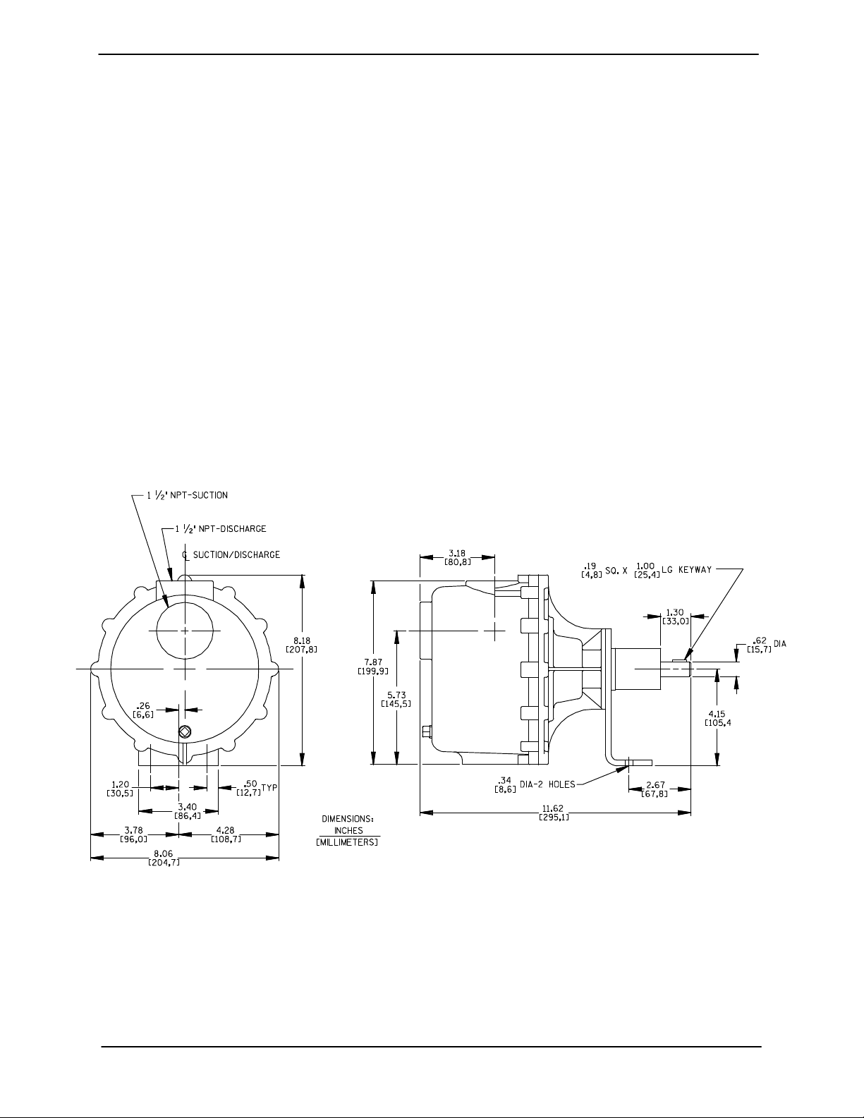
OUTLINE DRAWING
specific application. Since the pressure supplied
to the pump is critical to performance and safety,
be sure to limit the incoming pressure to 50% of the
maximum permissible operating pressure as
shown on the pump performance curve (see Sec
tion E, Page 1).
For further assistance, contact your Gorman‐Rupp
distributor or the Gorman‐Rupp Company.
Pump Dimensions
See Figure 1 for the approximate physical dimen
sions of this pump.
Figure 1. Pump Model 81 1/2P47A-B
PREINSTALLATION INSPECTION
The pump assembly was inspected and tested be
fore shipment from the factory. Before installation,
inspect the pump for damage which may have oc
curred during shipment. Check as follows:
a. Inspect the pump for cracks, dents, damaged
threads, and other obvious damage.
b. Check for and tighten loose attaching hard
ware. Since gaskets tend to shrink after dry
ing, check for loose hardware at mating sur
faces.
PAGE B - 1INSTALLATION
OM-02163 80 SERIES
c. Carefully read all tags, decals, and markings
on the pump assembly, and perform all duties
indicated. Note that the pump shaft rotates in
the required direction.
Only operate this pump in the direction in
dicated by the arrow on the pump body
and on the accompanying decal. Other
wise, the impeller could become loosened
from the shaft and seriously damage the
pump. Refer to Rotation in OPERATION,
Section C.
d. Check levels and lubricate as necessary. Re
fer to LUBRICATION in the MAINTENANCE
AND REPAIR section of this manual and per
form duties as instructed.
e. If the pump has been stored for more than 12
months, some of the components or lubri
cants may have exceeded their maximum
shelf life. These must be inspected or re
placed to ensure maximum pump service.
If the maximum shelf life has been exceeded, or if
anything appears to be abnormal, contact your
Gorman‐Rupp distributor or the factory to deter
mine the repair or updating policy. Do not put the
pump into service until appropriate action has
been taken.
equipment such as suction and discharge hoses
or piping before attempting to lift existing, installed
units.
The pump assembly can be seriously
damaged if the cables or chains used to lift
and move the unit are improperly wrapped
around the pump.
The pump casing, flanges and seal plate
are made of fiberglass‐reinforced polyes
ter, which can crack under impact or
shock. Take every precaution against
dropping the pump or striking pump com
ponents.
Mounting
Locate the pump in an accessible place as close as
practical to the liquid being pumped. Level mount
ing is essential for proper operation.
The pump may have to be supported or shimmed
to provide for level operation or to eliminate vibra
tion.
SUCTION AND DISCHARGE PIPING
POSITIONING PUMP
Pump performance is adversely effected by in
creased suction lift, discharge elevation, and fric
tion losses. See the performance curve on Page
E-1 to be sure your overall application allows
pump to operate within the safe operation range.
Use lifting and moving equipment in
good repair and with adequate capacity
to prevent injuries to personnel or dam
age to equipment. Suction and dis
charge hoses and piping must be re
moved from the pump before lifting.
Lifting
Pump unit weights will vary depending on the
mounting and drive provided. Check the shipping
tag on the unit packaging for the actual weight, and
use lifting equipment with appropriate capacity.
Drain the pump and remove all customer‐installed
PAGE B - 2 INSTALLATION
Materials
Either pipe or hose maybe used for suction and
discharge lines; however, the materials must be
compatible with the liquid being pumped. If hose is
used in suction lines, it must be the rigid‐wall, rein
forced type to prevent collapse under suction. Us
ing piping couplings in suction lines is not recom
mended.
Line Configuration
Keep suction and discharge lines as straight as
possible to minimize friction losses. Make mini
 Loading...