

GORMAN-RUPP PUMPS 80 Series, 82E1-L100W FT4-X Installation, Operation, And Maintenance Manual With Parts List
OM-06771-01
October 19, 2015
INSTALLATION, OPERATION,
AND MAINTENANCE MANUAL
WITH PARTS LIST
80 SERIES PUMP
MODEL
82E1-L100W FT4-X
GORMAN‐RUPP PUMPS
www.grpumps.com
e2015 Gorman‐Rupp Pumps Printed in U.S.A.

Register your new
Gorman‐Rupp pump online at
www.grpumps.com
Valid serial number and e‐mail address required.
The engine exhaust from this
product contains chemicals
known to the State of California to
cause cancer, birth defects or
other reproductive harm.
RECORD YOUR PUMP MODEL AND SERIAL NUMBER
Please record your pump model and serial number in the
spaces provided below. Your Gorman‐Rupp distributor
needs this information when you require parts or service.
Pump Model:
Serial Number:

TABLE OF CONTENTS
INTRODUCTION PAGE I - 1.................................................
SAFETY - SECTION A PAGE A - 1...........................................
INSTALLATION - SECTION B PAGE B - 1....................................
Pump Dimensions PAGE B - 1.....................................................
PREINSTALLATION INSPECTION PAGE B - 2............................................
POSITIONING PUMP PAGE B - 2.......................................................
Lifting PAGE B - 2.................................................................
Mounting PAGE B - 2.............................................................
SUCTION AND DISCHARGE PIPING PAGE B - 2.........................................
Materials PAGE B - 2..............................................................
Line Configuration PAGE B - 3......................................................
Connections to Pump PAGE B - 3..................................................
Gauges PAGE B - 3...............................................................
SUCTION LINES PAGE B - 3...........................................................
Fittings PAGE B - 3...............................................................
Strainers PAGE B - 3..............................................................
Sealing PAGE B - 3...............................................................
Suction Lines In Sumps PAGE B - 3.................................................
Suction Line Positioning PAGE B - 4................................................
DISCHARGE LINES PAGE B - 4........................................................
Siphoning PAGE B - 4.............................................................
Valves PAGE B - 4................................................................
Bypass Lines PAGE B - 5..........................................................
GROUNDING PAGE B - 5.............................................................
OPERATION - SECTION C PAGE C - 1......................................
PRIMING PAGE C - 1.................................................................
STARTING PAGE C - 1................................................................
OPERATION PAGE C - 2..............................................................
Lines With a Bypass PAGE C - 2....................................................
Lines Without a Bypass PAGE C - 2.................................................
Leakage PAGE C - 2..............................................................
Liquid Temperature And Overheating PAGE C - 2.....................................
Strainer Check PAGE C - 2.........................................................
Pump Vacuum Check PAGE C - 2..................................................
STOPPING PAGE C - 3................................................................
Cold Weather Preservation PAGE C - 3..............................................
TROUBLESHOOTING - SECTION D PAGE D - 1..............................
PREVENTIVE MAINTENANCE PAGE D - 3...............................................
i

TABLE OF CONTENTS
(continued)
PUMP MAINTENANCE AND REPAIR - SECTION E PAGE E - 1................
STANDARD PERFORMANCE CURVE PAGE E - 1........................................
PARTS LISTS:
Pump Model PAGE E - 3..........................................................
Pump End PAGE E - 5............................................................
PUMP AND SEAL DISASSEMBLY AND REASSEMBLY PAGE E - 6.........................
Suction Check Valve Disassembly PAGE E - 6........................................
Pump Casing Removal PAGE E - 6.................................................
Impeller Removal PAGE E - 7......................................................
Seal Removal PAGE E - 7..........................................................
Seal Reassembly and Installation PAGE E - 7........................................
Impeller Installation And Adjustment PAGE E - 9......................................
Pump Casing Installation PAGE E - 9................................................
Suction Check Valve Installation PAGE E - 9.........................................
Final Pump Assembly PAGE E - 9..................................................
LUBRICATION PAGE E - 9.............................................................
Seal Assembly PAGE E - 9.........................................................
Engine PAGE E - 9................................................................
ENGINE MODIFICATIONS PAGE E - 9..................................................
ii
80 SERIES
OM-06771
INTRODUCTION
Thank You for purchasing a Gorman‐Rupp pump.
Read this manual carefully to learn how to safely
install and operate your pump. Failure to do so
could result in personal injury or damage to the
pump.
Because pump installations are seldom identical,
this manual cannot possibly provide detailed in
structions and precautions for every aspect of
each specific application. Therefore, it is the re
sponsibility of the owner/installer of the pump to
ensure that applications not addressed in this
manual are performed only after establishing that
neither operator safety nor pump integrity are com
promised by the installation. Pumps and related
equipment must be installed and operated ac
cording to all national, local and industry stan
dards.
If there are any questions regarding the pump or
its application which are not covered in this man
ual or in other literature accompanying this unit,
please contact your Gorman‐Rupp distributor, or
The Gorman‐Rupp Company:
HAZARD AND INSTRUCTION
DEFINITIONS
The following are used to alert maintenance per
sonnel to procedures which require special atten
tion, to those which could damage equipment, and
to those which could be dangerous to personnel:
Immediate hazards which WILL result in
severe personal injury or death. These
instructions describe the procedure re
quired and the injury which will result
from failure to follow the procedure.
Hazards or unsafe practices which
COULD result in severe personal injury
or death. These instructions describe
the procedure required and the injury
which could result from failure to follow
the procedure.
The Gorman‐Rupp Company
P.O. Box 1217
Mansfield, Ohio 44901-1217
Phone: (419) 755-1011
or:
Gorman‐Rupp of Canada Limited
70 Burwell Road
St. Thomas, Ontario N5P 3R7
Phone: (519) 631-2870
For information or technical assistance on the
power source, contact the power source manufac
turer's local dealer or representative.
Hazards or unsafe practices which COULD
result in minor personal injury or product
or property damage. These instructions
describe the requirements and the possi
ble damage which could result from failure
to follow the procedure.
NOTE
Instructions to aid in installation, operation, and
maintenance or which clarify a procedure.
PAGE I - 1INTRODUCTION
80 SERIES
OM-06771
SAFETY - SECTION A
This information applies to 80 Series
engine driven pumps. Refer to the
manual accompanying the engine
before attempting to begin operation.
Because pump installations are seldom
identical, this manual cannot possibly
provide detailed instructions and pre
cautions for each specific application.
Therefore, it is the owner/installer's re
sponsibility to ensure that applications
not addressed in this manual are per
formed only after establishing that nei
ther operator safety nor pump integrity
are compromised by the installation.
The engine used in this pump is not
standard. It has been modified for use in
handling gasoline and other petroleum
products in a well ventilated, non‐flam
mable atmosphere free of combustible
hazards. It cannot be further modified
without affecting performance and safe
ty factors. The shield and spark arrest
ing modifications must be inspected
and maintained regularly while the unit
is in use. Refer to the manual accompa
nying the engine before attempting to
start the engine.
4. Check the temperature before
opening any covers, plates, or
plugs.
5. Close the suction and discharge
valves.
6. Vent the pump slowly and cau
tiously.
7. Drain the pump.
This pump is designed to handle water,
fuel and other petroleum products in a
non‐flammable atmosphere. Do not at
tempt to pump corrosive materials or
any liquids which may damage the
pump or endanger personnel as a result
of pump failure.
After the pump has been installed, make
certain that the pump and all piping or
hose connections are tight, properly
supported and secure before operation.
Before attempting to open or service the
pump:
1. Familiarize yourself with this man
ual.
2. Shut down the engine and take
precautions to ensure that the
pump will remain inoperative.
3. Allow the pump to completely cool
if overheated.
Do not operate the pump against a
closed discharge valve for long periods
of time. If operated against a closed dis
charge valve, pump components will
deteriorate, and the liquid could come
to a boil, build pressure, and cause the
pump casing to rupture or explode.
PAGE A - 1SAFETY
OM-06771
80 SERIES
Do not remove plates, covers, gauges,
pipe plugs, or fittings from an over
heated pump. Vapor pressure within the
pump can cause parts being disen
gaged to be ejected with great force.
Allow the pump to completely cool be
fore servicing.
Overheated pumps can cause severe
burns and injuries. if overheating of the
pump occurs:
1. Stop the pump immediately.
2. Ventilate the area.
3. Allow the pump to completely cool.
4. Check the temperature before
opening any covers, plates,
gauges, or plugs.
5. Vent the pump slowly and cau
tiously.
6. Refer to instructions in this manual
before restarting the pump.
Do not operate an internal combustion
engine in an explosive atmosphere.
When operating internal combustion
engines in an enclosed area, make cer
tain that exhaust fumes are piped to the
outside. These fumes contain carbon
monoxide, a deadly gas that is color
less, tasteless, and odorless.
Fuel used by internal combustion
engines presents an extreme explosion
and fire hazard. Make certain that all
fuel lines are securely connected and
free of leaks. Never refuel a hot or run
ning engine. Avoid overfilling the fuel
tank. Always use the correct type of fuel.
If this pump is used with volatile and/or
flammable liquids, be certain proper
safety practices are followed before op
erating or servicing the pump. Provide
adequate ventilation, prohibit smoking,
wear static‐resistant clothing and
shoes. Clean up all fuel spills immedi
ately after occurrence.
Never tamper with the governor to gain
more power. The governor establishes
safe operating limits that should not be
exceeded. See the performance curve
on page E-1 for the maximum continu
ous operating speed for this pump.
Pumps and related equipment must be in
stalled and operated according to all na
tional, local and industry standards.
PAGE A - 2 SAFETY
80 SERIES OM-06771
INSTALLATION - SECTION B
Review all SAFETY information in Section A.
Since pump installations are seldom identical, this
section offers only general recommendations and
practices required to inspect, position, and ar
range the pump and piping.
Most of the information pertains to a standard
static lift application where the pump is positioned
above the free level of liquid to be pumped.
If installed in a flooded suction application where
the liquid is supplied to the pump under pressure,
some of the information such as mounting, line
configuration, and priming must be tailored to the
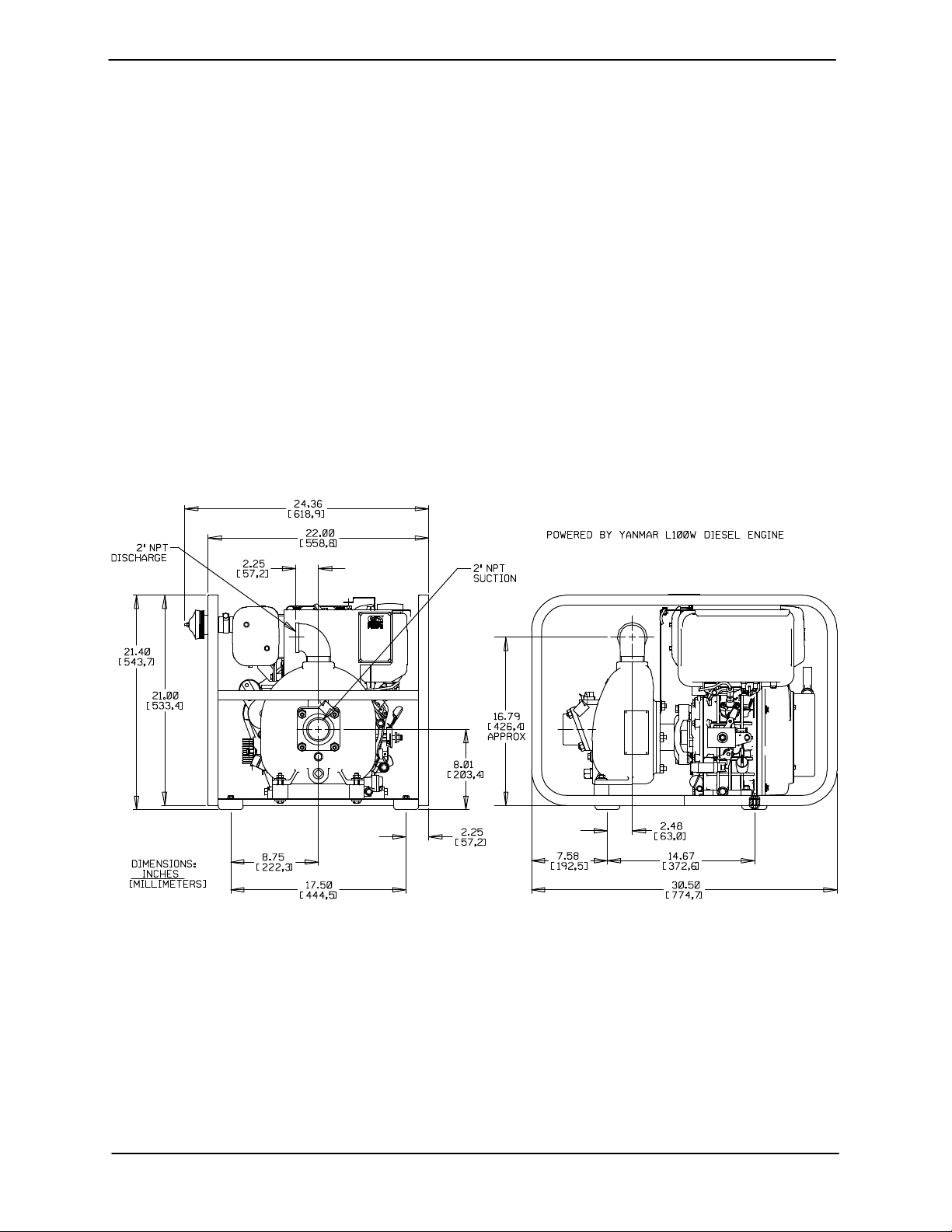
OUTLINE DRAWING
specific application. Since the pressure supplied
to the pump is critical to performance and safety,
be sure to limit the incoming pressure to 50% of the
maximum permissible operating pressure as
shown on the pump performance curve (see Sec
tion E, Page 1).
For further assistance, contact your Gorman‐Rupp
distributor or the Gorman‐Rupp Company.
Pump Dimensions
See Figure 1 for the approximate physical dimen
sions of this pump.
Figure 1. Pump Model 82E1-L100W FT4-X
PREINSTALLATION INSPECTION
The pump assembly was inspected and tested be
fore shipment from the factory. Before installation,
inspect the pump for damage which may have oc
curred during shipment. Check as follows:
a. Inspect the pump and engine for cracks,
dents, damaged threads, and other obvious
damage.
b. Check for and tighten loose attaching hard
ware. Since gaskets tend to shrink after dry
ing, check for loose hardware at mating sur
faces.
c. Carefully read all tags, decals, and markings
on the pump assembly, and perform all duties
indicated.
PAGE B - 1INSTALLATION

OM-06771 80 SERIES
d. Check levels and lubricate as necessary. Re
fer to LUBRICATION in the MAINTENANCE
AND REPAIR section of this manual and per
form duties as instructed.
e. Check all special engine modifications such
as spark arresting muffler, fuel guard and roll
cage for loose mounting hardware. Check for
and install the rubber foot mounting kit and
spark arrester muffler that are shipped loose.
f. If the pump and
more than 12 months, some of the compo
nents or lubricants may have exceeded their
maximum shelf life. These must be inspected
or replaced to ensure maximum pump serv
ice.
If the maximum shelf life has been exceeded, or if
anything appears to be abnormal, contact your
Gorman‐Rupp distributor or the factory to deter
mine the repair or updating policy. Do not put the
pump into service until appropriate action has
been taken.
engine have been stored for
POSITIONING PUMP
Mounting
Locate the pump in an accessible place as close as
practical to the liquid being pumped. Level mount
ing is essential for proper operation.
The pump may have to be supported or shimmed
to provide for level operation or to eliminate vibra
tion.
If the pump has been mounted on a moveable
base, make certain the base is stationary by setting
the brake and blocking the wheels before attempt
ing to operate the pump.
To ensure sufficient lubrication and fuel supply to
the engine, do not position the pump and engine
more than 15
tion. The pump and engine may be positioned up
to 30_ off horizontal for intermittent operation
only; however, the engine manufacturer should be
consulted for continuous operation at angles
greater than 15_.
_
off horizontal for continuous opera
SUCTION AND DISCHARGE PIPING
Pump performance is adversely effected by in
creased suction lift, discharge elevation, and fric
tion losses. See the performance curve on Page
E-1 to be sure your overall application allows the
pump to operate within the safe operation range.
Materials
Lifting
Pump unit weights will vary depending on the
mounting and drive provided. Check the shipping
tag on the unit packaging for the actual weight, and
use lifting equipment with appropriate capacity.
Drain the pump and remove all customer‐installed
equipment such as suction and discharge hoses
or piping before attempting to lift existing, installed
units.
The pump assembly can be seriously
damaged if the cables or chains used to lift
and move the unit are improperly wrapped
around the pump.
PAGE B - 2 INSTALLATION
Either pipe or hose maybe used for suction and
discharge lines; however, the materials must be
compatible with the liquid being pumped. If hose is
used in suction lines, it must be the rigid‐wall, rein
forced type to prevent collapse under suction. Us
ing piping couplings in suction lines is not recom
mended.
Line Configuration
Keep suction and discharge lines as straight as
possible to minimize friction losses. Make mini
mum use of elbows and fittings, which substan
tially increase friction loss. If elbows are necessary,
use the long‐radius type to minimize friction loss.
Connections to Pump
Before tightening a connecting flange, align it ex
actly with the pump port. Never pull a pipe line into
 Loading...