

GORMAN-RUPP PUMPS 6500 Series, 6506A60-B Installation, Operation, And Maintenance Manual With Parts List
Page 1

OM-06682-01
October 27, 2014
INSTALLATION, OPERATION,
AND MAINTENANCE MANUAL
WITH PARTS LIST
6500 SERIES PUMP
MODEL
6506A60-B
GORMAN‐RUPP PUMPS
www.grpumps.com
e2014 Gorman‐Rupp Pumps Printed in U.S.A.
Page 2

Register your new
Gorman‐Rupp pump online at
www.grpumps.com
Valid serial number and e‐mail address required.
RECORD YOUR PUMP MODEL AND SERIAL NUMBER
Please record your pump model and serial number in the
spaces provided below. Your Gorman‐Rupp distributor
needs this information when you require parts or service.
Pump Model:
Serial Number:
Page 3

TABLE OF CONTENTS
INTRODUCTION PAGE I - 1.................................................
SAFETY ‐ SECTION A PAGE A - 1............................................
INSTALLATION - SECTION B PAGE B - 1....................................
PREINSTALLATION INSPECTION PAGE B - 1............................................
POSITIONING PUMP PAGE B -1.......................................................
Lifting PAGE B - 1.................................................................
Mounting PAGE B - 2.............................................................
SUCTION AND DISCHARGE PIPING PAGE B - 2.........................................
Materials PAGE B - 2..............................................................
Line Configuration PAGE B - 2......................................................
Connections to Pump PAGE B - 2..................................................
Gauges PAGE B - 2...............................................................
SUCTION LINES PAGE B - 2...........................................................
Fittings PAGE B - 2...............................................................
Strainers PAGE B - 2..............................................................
Sealing PAGE B - 2...............................................................
Suction Lines In Sumps PAGE B - 2.................................................
Suction Line Positioning PAGE B - 3................................................
DISCHARGE LINES PAGE B - 4........................................................
Siphoning PAGE B - 4.............................................................
Valves PAGE B - 4................................................................
ALIGNMENT PAGE B - 4..............................................................
Coupled Drives PAGE B - 4........................................................
V‐Belt Drives PAGE B - 5...........................................................
ELECTRICAL CONNECTIONS PAGE B - 5...............................................
OPERATION - SECTION C PAGE C - 1......................................
PRIMING PAGE C - 1.................................................................
Hand Primers PAGE C - 1..........................................................
Exhaust Primers PAGE C - 1.......................................................
Auxiliary Ejectors PAGE C - 2.......................................................
Vacuum Pumps PAGE C - 2........................................................
STARTING PAGE C - 2................................................................
Rotation PAGE C - 2..............................................................
OPERATION PAGE C - 2..............................................................
Leakage PAGE C - 2..............................................................
Liquid Temperature And Overheating PAGE C - 2.....................................
Strainer Check PAGE C - 3.........................................................
Pump Vacuum Check PAGE C - 3..................................................
Operational Checks PAGE C - 3....................................................
STOPPING PAGE C - 3................................................................
Cold Weather Preservation PAGE C - 4..............................................
BEARING TEMPERATURE CHECK PAGE C - 4..........................................
LUBRICATION PAGE C - 4.............................................................
Power Source PAGE C - 5.........................................................
i
Page 4

TABLE OF CONTENTS
(continued)
TROUBLESHOOTING - SECTION D PAGE D - 1..............................
PREVENTIVE MAINTENANCE PAGE D - 3...............................................
PUMP MAINTENANCE AND REPAIR ‐ SECTION E PAGE E - 1.................
STANDARD PERFORMANCE CURVE PAGE E - 1........................................
PARTS LIST:
Pump End Assembly PAGE E - 3...................................................
Repair Rotating Assembly PAGE E - 5...............................................
PUMP AND SEAL DISASSEMBLY AND REASSEMBLY PAGE E - 6.........................
Suction Head and Wear Ring Removal PAGE E - 7....................................
Pump Casing Removal PAGE E - 7.................................................
Draining Oil From Seal Cavity PAGE E - 7............................................
Impeller Removal PAGE E - 7......................................................
Seal Removal PAGE E - 7..........................................................
Separating Rotating Assembly From Power Source PAGE E - 8........................
Shaft and Bearing Removal And Disassembly PAGE E - 8.............................
Shaft and Bearing Reassembly and Installation PAGE E - 9............................
Securing Rotating Assembly to Power Source PAGE E - 10.............................
Seal Reassembly and Installation PAGE E - 10........................................
Impeller Installation and Adjustment PAGE E - 11......................................
Pump Casing Installation PAGE E - 12................................................
Suction Head and Wear Ring Installation PAGE E - 12..................................
LUBRICATION PAGE E - 12.............................................................
Seal Assembly PAGE E - 12.........................................................
Bearings PAGE E - 12..............................................................
ii
Page 5
6500 SERIES
OM-06682
INTRODUCTION
Thank You for purchasing a Gorman‐Rupp pump.
Read this manual carefully to learn how to safely
install and operate your pump. Failure to do so
could result in personal injury or damage to the
pump.
Because pump installations are seldom identical,
this manual cannot possibly provide detailed in
structions and precautions for every aspect of
each specific application. Therefore, it is the re
sponsibility of the owner/installer of the pump to
ensure that applications not addressed in this
manual are performed only after establishing that
neither operator safety nor pump integrity are com
promised by the installation. Pumps and related
equipment must be installed and operated ac
cording to all national, local and industry stan
dards.
If there are any questions regarding the pump or
its application which are not covered in this man
ual or in other literature accompanying this unit,
please contact your Gorman‐Rupp distributor, or
The Gorman‐Rupp Company:
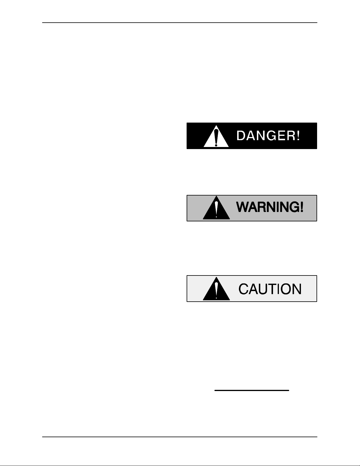
HAZARD AND INSTRUCTION
DEFINITIONS
The following are used to alert maintenance per
sonnel to procedures which require special atten
tion, to those which could damage equipment, and
to those which could be dangerous to personnel:
Immediate hazards which WILL result in
severe personal injury or death. These
instructions describe the procedure re
quired and the injury which will result
from failure to follow the procedure.
Hazards or unsafe practices which
COULD result in severe personal injury
or death. These instructions describe
the procedure required and the injury
which could result from failure to follow
the procedure.
The Gorman‐Rupp Company
P.O. Box 1217
Mansfield, Ohio 44901-1217
Phone: (419) 755-1011
or:
Gorman‐Rupp of Canada Limited
70 Burwell Road
St. Thomas, Ontario N5P 3R7
Phone: (519) 631-2870
For information or technical assistance on the
power source, contact the power source manufac
turer's local dealer or representative.
Hazards or unsafe practices which COULD
result in minor personal injury or product
or property damage. These instructions
describe the requirements and the possi
ble damage which could result from failure
to follow the procedure.
NOTE
Instructions to aid in installation, operation, and
maintenance or which clarify a procedure.
PAGE I - 1INTRODUCTION
Page 6
6500 SERIES
SAFETY ‐ SECTION A
This information applies to 6500 Series
basic pumps. Gorman‐Rupp has no
control over or particular knowledge of
the power source which will be used.
Refer to the manual accompanying the
power source before attempting to be
gin operation.
Because pump installations are seldom
identical, this manual cannot possibly
provide detailed instructions and pre
cautions for each specific application.
Therefore, it is the owner/installer's re
sponsibility to ensure that applications
not addressed in this manual are per
formed only after establishing that nei
ther operator safety nor pump integrity
are compromised by the installation.
OM-06682
Death or serious personal injury and
damage to the pump or components
can occur if proper lifting procedures
are not observed. Make certain that
hoists, chains, slings or cables are in
good working condition and of suffi
cient capacity and that they are posi
tioned so that loads will be balanced
and the pump or components will not be
damaged when lifting. Suction and dis
charge hoses and piping must be re
moved from the pump before lifting. Lift
the pump or component only as high as
necessary and keep personnel away
from suspended objects.
Before attempting to open or service the
pump:
1. Familiarize yourself with this man
ual.
2. Lock out or disconnect the power
source to ensure that the pump will
remain inoperative.
3. Allow the pump to completely cool
if overheated.
4. Check the temperature before
opening any covers, plates, or
plugs.
5. Close the suction and discharge
valves.
6. Vent the pump slowly and cau
tiously.
7. Drain the pump.
After the pump has been installed, make
certain that the pump and all piping or
hose connections are tight, properly
supported and secure before operation.
Do not operate the pump without the
shields and/or guards in place over the
drive shaft, belts, and/or couplings, or
other rotating parts. Exposed rotating
parts can catch clothing, fingers, or
tools, causing severe injury to person
nel.
Do not operate the pump against a
closed discharge valve for long periods
of time. If operated against a closed dis
PAGE A - 1SAFETY
Page 7
charge valve, pump components will
deteriorate, and the liquid could come
to a boil, build pressure, and cause the
pump casing to rupture or explode.
Overheated pumps can cause severe
burns and injuries. If overheating of the
pump occurs:
1. Stop the pump immediately.
2. Ventilate the area.
3. Allow the pump to completely cool.
4. Check the temperature before
opening any covers, plates,
gauges, or plugs.
5. Vent the pump slowly and cau
tiously.
6. Refer to instructions in this manual
before restarting the pump.
6500 SERIESOM-06682
Do not remove plates, covers, gauges,
pipe plugs, or fittings from an over
heated pump. Vapor pressure within the
pump can cause parts being disen
gaged to be ejected with great force. Al
low the pump to completely cool before
servicing.
Never run this pump backwards. Be cer
tain that rotation is correct before fully
engaging the pump.
Pumps and related equipment must be in
stalled and operated according to all na
tional, local and industry standards.
PAGE A - 2 SAFETY
Page 8
6500 SERIES OM-06682
INSTALLATION - SECTION B
Review all SAFETY information in Section A.
Since pump installations are seldom identical, this
section offers only general recommendations and
practices required to inspect, position, and ar
range the pump and piping.
Most of the information pertains to a flooded suc
tion application where the liquid is supplied to the
pump under pressure. Since the pressure sup
plied to the pump is critical to performance and
safety, be sure to limit the incoming pressure to
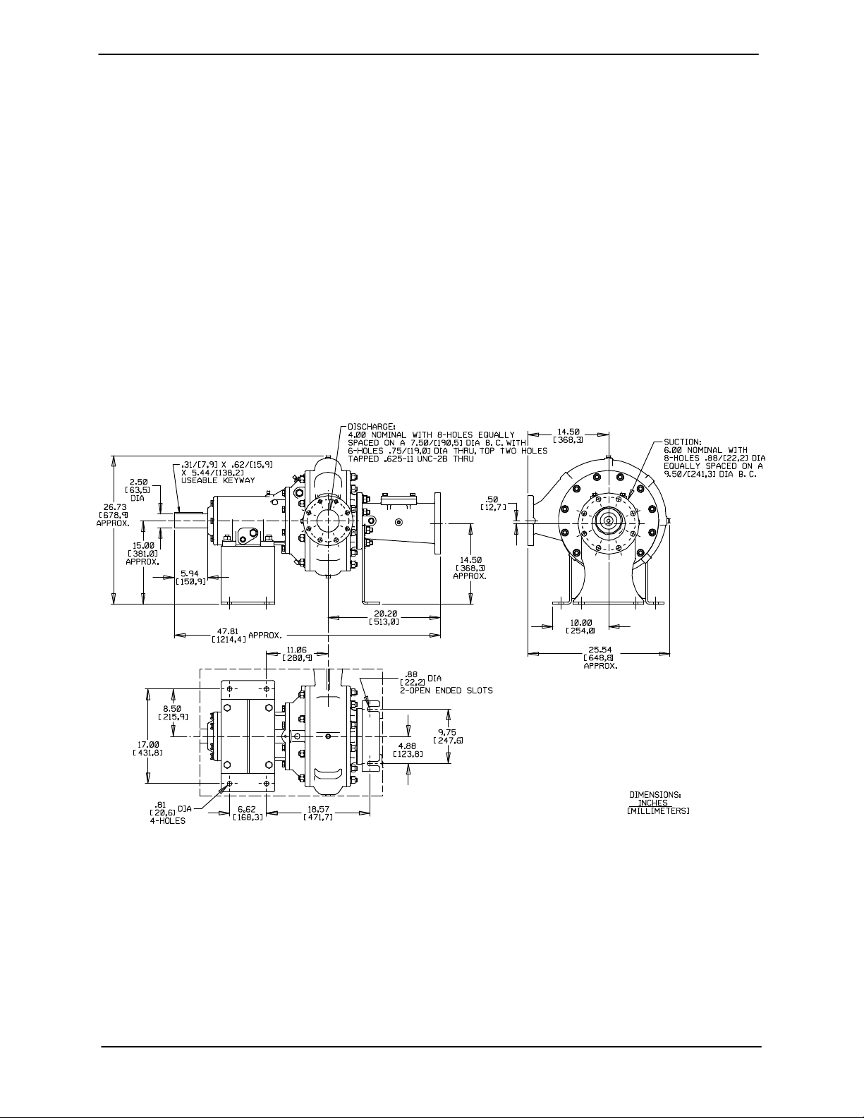
OUTLINE DRAWING
50% of the maximum permissible operating pres
sure as shown on the pump performance curve
(see Section E, Page 1).
For further assistance, contact your Gorman‐Rupp
distributor or the Gorman‐Rupp Company.
Pump Dimensions
See Figure 1 for the approximate physical dimen
sions of this pump.
Figure 1. Pump Model 6506A60-B
PREINSTALLATION INSPECTION
The pump assembly was inspected and tested be
fore shipment from the factory. Before installation,
inspect the pump for damage which may have oc
curred during shipment. Check as follows:
a. Inspect the pump and engine for cracks,
dents, damaged threads, and other obvious
damage.
b. Check for and tighten loose attaching hard
ware. Since gaskets tend to shrink after dry
ing, check for loose hardware at mating sur
faces.
c. Carefully read all tags, decals, and markings
on the pump assembly, and perform all duties
indicated.
d. Check levels and lubricate as necessary. Re
fer to LUBRICATION in the MAINTENANCE
PAGE B - 1INSTALLATION
Page 9
OM-06682 6500 SERIES
AND REPAIR section of this manual and per
form duties as instructed.
e. If the pump has been stored for more than 12
months, some of the components or lubri
cants may have exceeded their maximum
shelf life. These must be inspected or re
placed to ensure maximum pump service.
If the maximum shelf life has been exceeded, or if
anything appears to be abnormal, contact your
Gorman‐Rupp distributor or the factory to deter
mine the repair or updating policy. Do not put the
pump into service until appropriate action has
been taken.
POSITIONING PUMP
Death or serious personal injury and
damage to the pump or components
can occur if proper lifting procedures
are not observed. Make certain that
hoists, chains, slings or cables are in
good working condition and of suffi
cient capacity and that they are posi
tioned so that loads will be balanced
and the pump or components will not be
damaged when lifting. Suction and dis
charge hoses and piping must be re
moved from the pump before lifting. Lift
the pump or component only as high as
necessary and keep personnel away
from suspended objects.
Mounting
Locate the pump in an accessible place as close as
practical to the liquid being pumped. Level mount
ing is essential for proper operation.
Proper mounting of the pump, driver and base is
critical to the performance of the pump. Improper
mounting can result in vibration, which can cause
damage to the pump and/or other system compo
nents.
The pumping unit must be securely mounted to a
foundation that is heavy enough to absorb any vi
bration, strain or shock, while providing perma
nent, rigid support for the unit.
Because pump installations vary due to the specif
ic application, this manual cannot possibly antici
pate and provide detailed instructions for every in
stallation. Therefore, it is recommended that the in
staller of the unit follow the recommendations pro
vided by the Hydraulic Institute in their Rotodynam
ic Centrifugal Pump Design and Application manu
al when designing and fabricating the foundation
upon which the pump, base and driver will be
mounted.
SUCTION AND DISCHARGE PIPING
The following is provided as general information for
suction and discharge piping. Because pump in
stallations vary due to the specific application, this
manual cannot possibly anticipate and provide de
tailed instructions for every installation. Therefore,
it is recommended that the installer follow the rec
ommendations provided by the Hydraulic Institute
in their Pump Piping for Rotodynamic Pumps man
ual for layout, design and installation of the system
piping.
Materials
Lifting
Pump unit weights will vary depending on the
mounting and drive provided. Check the shipping
tag on the unit packaging for the actual weight, and
use lifting equipment with appropriate capacity.
Drain the pump and remove all customer‐installed
equipment such as suction and discharge hoses
or piping before attempting to lift existing, installed
units.
PAGE B - 2 INSTALLATION
Materials used in piping must be compatible with
the liquid being pumped. Using piping couplings
in suction lines is not recommended.
Line Configuration
Keep suction and discharge lines as straight as
possible to minimize friction losses. Make mini
mum use of elbows and fittings, which substan
tially increase friction loss. If elbows are necessary,
use the long‐radius type to minimize friction loss.
Page 10
6500 SERIES OM-06682
Connections to Pump
Before tightening a connecting flange, align it ex
actly with the pump port. Never pull a pipe line into
place by tightening the flange bolts and/or cou
plings.
Lines near the pump must be independently sup
ported to avoid strain on the pump which could
cause excessive vibration, decreased bearing life,
and increased shaft and seal wear.
Gauges
Most pumps are drilled and tapped for installing
discharge pressure and vacuum suction gauges.
If these gauges are desired for pumps that are not
tapped, drill and tap the suction and discharge
lines not less than 18 inches (457,2 mm) from the
suction and discharge ports and install the lines.
Installation closer to the pump may result in erratic
readings.
SUCTION LINES
To avoid air pockets which could affect pump prim
ing, the suction line must be as short and direct as
possible.
Fittings
Suction lines should be the same size as the pump
inlet. If reducers are used in suction lines, they
should be the eccentric type, and should be in
stalled with the flat part of the reducers uppermost
to avoid creating air pockets. Valves are not nor
mally used in suction lines, but if a valve is used for
isolation purposes, install it with the stem horizon
tal to avoid air pockets.
Sealing
Since even a slight leak will affect pump perfor
mance, all connections in the suction line should
be sealed with pipe dope to ensure an airtight seal.
Follow the sealant manufacturer's recommenda
tions when selecting and applying the pipe dope.
The pipe dope should be compatible with the liquid
being pumped.
DISCHARGE LINES
Siphoning
Do not terminate the discharge line at a level lower
than that of the liquid being pumped unless a si
phon breaker is used in the line. Otherwise, a si
phoning action causing damage to the pump
could result.
Valves
If a throttling valve is desired in the discharge line,
use a valve as large as the largest pipe to minimize
friction losses. Never install a throttling valve in a
suction line.
With high discharge heads, it is recommended that
a throttling valve and a system check valve be in
stalled in the discharge line to protect the pump
from excessive shock pressure and reverse rota
tion when it is stopped.
If the application involves a high discharge
head, gradually close the discharge
throttling valve before stopping the pump.
Strainers
If a strainer is installed by the pump user, make cer
tain that the total area of the openings in the strain
er is at least three or four times the cross section of
the suction line, and that the openings will not per
mit passage of solids larger than the solids han
dling capability of the pump.
This pump is designed to handle up to 3‐inch (76,2
mm) diameter spherical solids.
ALIGNMENT
This pump is designed for direct coupled
drive only. Use of a V‐belt drive will dam
age the pump and void the pump warranty.
The alignment of the pump and its power source is
critical for trouble‐free mechanical operation. The
driver and pump must be mounted so that their
PAGE B - 3INSTALLATION
Page 11
OM-06682 6500 SERIES
shafts are aligned with and parallel to each other. It
is imperative that alignment be checked after the
pump and piping are installed, and before opera
tion.
NOTE
Check Rotation, Section C, before final alignment
of the pump.
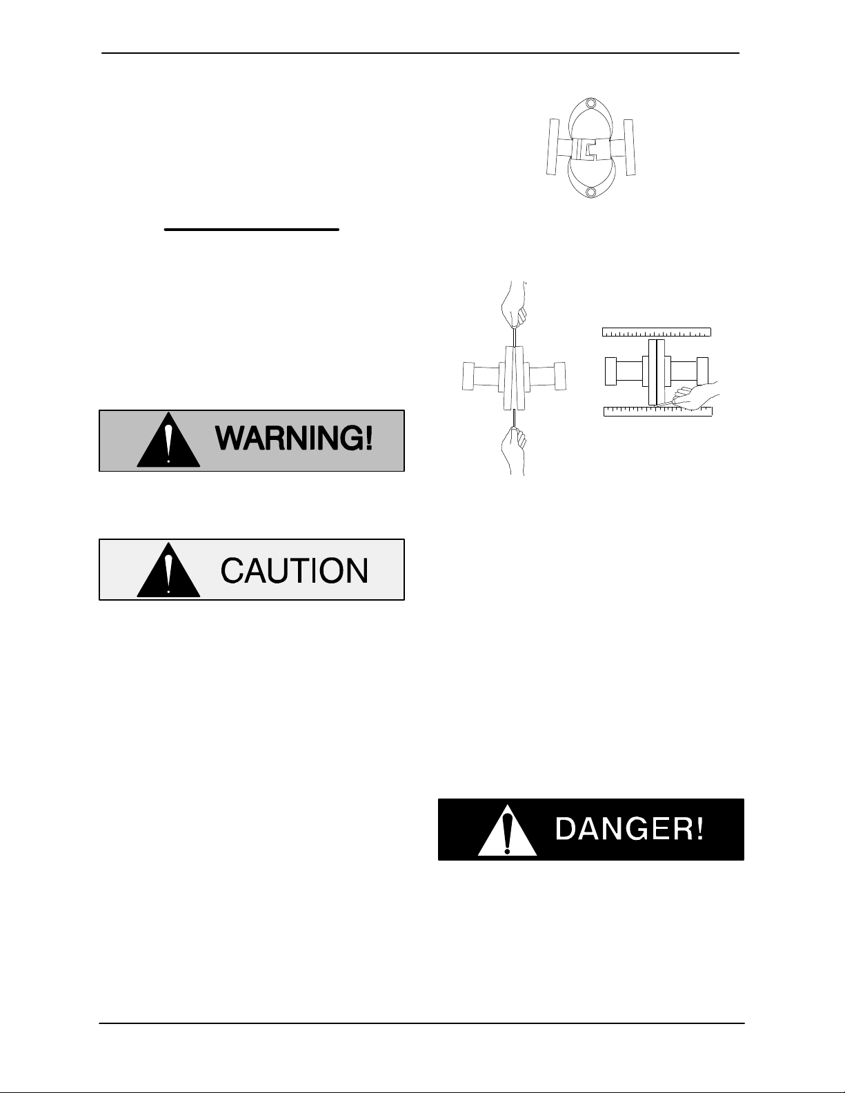
Figure 2A. Aligning Spider‐Type Couplings
When mounted at the Gorman‐Rupp factory, driver
and pump are aligned before shipment. Misalign
ment will occur in transit and handling. Pumps
must be checked and realigned before operation.
Before checking alignment, tighten the foundation
bolts. The pump casing feet and/or pedestal feet,
and the driver mounting bolts should also be tightly
secured.
When checking alignment, disconnect
the power source to ensure that the
pump will remain inoperative.
Adjusting the alignment in one direction
may alter the alignment in another direc
tion. check each procedure after altering
alignment.
Coupled Drives
When using couplings, the axis of the power
source must be aligned to the axis of the pump
shaft in both the horizontal and vertical planes.
Most couplings require a specific gap or clearance
between the driving and the driven shafts. Refer to
the coupling manufacturer's service literature.
Align spider insert type couplings by using calipers
to measure the dimensions on the circumference
of the outer ends of the coupling hub every 90_.
The coupling is in alignment when the hub ends
are the same distance apart at all points (see Fig
ure 2A).
Figure 2B. Aligning Non‐Spider Type Couplings
Align non‐spider type couplings by using a feeler
gauge or taper gauge between the coupling halves
every 90_. The coupling is in alignment when the
hubs are the same distance apart at all points (see
Figure 2B).
Check parallel adjustment by laying a straightedge
across both coupling rims at the top, bottom, and
side. When the straightedge rests evenly on both
halves of the coupling, the coupling is in horizontal
parallel alignment. If the coupling is misaligned,
use a feeler gauge between the coupling and the
straightedge to measure the amount of misalign
ment.
Do not operate the pump without the
guard in place over the rotating parts.
exposed rotating parts can catch cloth
ing, fingers, or tools, causing severe in
jury to personnel.
PAGE B - 4 INSTALLATION
Page 12
6500 SERIES
OPERATION - SECTION C
Review all SAFETY information in Section A.
Follow the instructions on all tags, labels and
decals attached to the pump.
This pump is designed to handle most
non‐volatile, non‐flammable liquids
containing specified entrained solids.
Do not attempt to pump volatile, corro
sive, or flammable liquids which may
damage the pump or endanger person
nel as a result of pump failure.
OM-06682
Allow an over‐heated pump to cool be
fore servicing. Do not remove plates,
covers, gauges, or fittings from an over‐
heated pump. Liquid within the pump
can reach boiling temperatures, and va
por pressure within the pump can cause
parts being disengaged to be ejected
with great force. After the pump cools,
drain the liquid from the pump by re
moving the casing drain plug. Use cau
tion when removing the plug to prevent
injury to personnel from hot liquid.
STARTING
Consult the operations manual furnished with the
power source.
OPERATION
Leakage
No leakage should be visible at pump mating sur
faces, or at pump connections or fittings. Keep all
line connections and fittings tight to maintain maxi
mum pump efficiency.
Liquid Temperature And Overheating
The maximum liquid temperature for this pump is
160_F (71_C). Do not apply it at a higher operating
temperature.
Overheating can occur if operated with the valves
in the suction or discharge lines closed. Operating
against closed valves could bring the liquid to a
boil, build pressure, and cause the pump to rup
ture or explode. If overheating occurs, stop the
pump and allow it to cool before servicing it. Refill
the pump casing with cool liquid.
Strainer Check
If a suction strainer has been installed by the user,
check the strainer regularly and clean it as neces
sary. The strainer should also be checked if pump
flow rate begins to drop. If a vacuum suction gauge
has been installed, monitor and record the read
ings regularly to detect strainer blockage.
Never introduce air or steam pressure into the
pump casing or piping to remove a blockage. This
could result in personal injury or damage to the
equipment. If backflushing is absolutely neces
sary, liquid pressure must be limited to 50% of the
maximum permissible operating pressure shown
on the pump performance curve (see Section E,
Page 1).
STOPPING
If the liquid being pumped is stopped abruptly,
damaging shock waves can be transmitted to the
pump and piping system. Soft‐start systems with
ramp up/ramp down starting and stopping capa
bilities are available where water hammer may be a
problem.
After stopping the pump, lock out or disconnect
the power source to ensure that the pump will re
main inoperative.
OPERATION PAGE C - 1
Page 13

OM-06682 6500 SERIES
Cold Weather Preservation
In below freezing conditions, drain the pump to
prevent damage from freezing. Also, clean out any
solids by flushing with a hose. Operate the pump
for approximately one minute; this will remove any
remaining liquid that could freeze the pump rotat
ing parts. If the pump will be idle for more than a
few hours, or if it has been pumping liquids con
taining a large amount of solids, drain the pump,
and flush it thoroughly with clean water. To prevent
large solids from clogging the drain port and pre
venting the pump from completely draining, insert
a rod or stiff wire in the drain port, and agitate the
liquid during the draining process. Clean out any
remaining solids by flushing with a hose.
BEARING TEMPERATURE CHECK
Bearings normally run at higher than ambient tem
peratures because of heat generated by friction.
Temperatures up to 160
_
F (71_C) are considered
normal for bearings, and they can operate safely to
_
at least 180
F (82_C).
Checking bearing temperatures by hand is inaccu
rate. Bearing temperatures can be measured ac
curately by placing a contact‐type thermometer
against the housing. Record this temperature for
future reference.
A sudden increase in bearing temperatures is a
warning that the bearings are at the point of failing
to operate properly. Make certain that the bearing
lubricant is of the proper viscosity and at the cor
rect level (see LUBRICATION in Section E). Bear
ing overheating can also be caused by shaft
misalignment and/or excessive vibration.
When pumps are first started, the bearings may
seem to run at temperatures above normal. Con
tinued operation should bring the temperatures
down to normal levels.
OPERATIONPAGE C - 2
Page 14
TROUBLESHOOTING - SECTION B
Review all SAFETY information in Section A.
Before attempting to open or service the
pump:
1. Familiarize yourself with this manual.
2. Lock out or disconnect the power
source and take the necessary pre
cautions to ensure that the pump will
remain inoperative.
3. Allow the pump to completely cool if
overheated.
4. Check the temperature before open
ing any covers, plates, or plugs.
5. Close the suction and discharge
valves.
6. Vent the pump slowly and cautiously.
7. Drain the pump.
OM-066826500 SERIES
Table D‐1 Troubleshooting Chart
TROUBLE POSSIBLE CAUSE PROBABLE REMEDY
PUMP FAILS TO PRIME Auxiliary priming device faulty or im
properly installed.
Discharge check valve open.
Air leak in suction line.
Lining of suction hose collapsed.
Leaking or worn seal or pump gas
ket.
Strainer clogged.
PUMP STOPS OR FAILS
TO DELIVER RATED
FLOW OR PRESSURE
Air leak in suction line.
Lining of suction hose collapsed.
Suction intake not submerged at
proper level or sump too small.
Repair priming device or check
installation.
Check position of handle; close
valve.
Correct leak.
Replace suction hose.
Check pump vacuum. Replace leak
ing or worn seal or gasket.
Check strainer and clean if neces
sary.
Correct leak.
Replace suction hose.
Check installation and correct sub
mergence as needed.
Strainer clogged.
TROUBLESHOOTING PAGE D - 1
Check strainer and clean if neces
sary.
Page 15

OM-06682 6500 SERIES
Table D‐1 Troubleshooting Chart (Continued)
TROUBLE POSSIBLE CAUSE PROBABLE REMEDY
PUMP STOPS OR FAILS
TO DELIVER RATED
FLOW OR PRESSURE
(cont.)
Impeller or other wearing parts worn
or damaged.
Leaking or worn seal or pump gas
ket.
Replace worn or damaged parts.
Check that impeller is properly cen
tered and rotates freely.
Check pump vacuum. Replace leak
ing or worn seal or gasket.
PUMP REQUIRES TOO
MUCH POWER
PUMP CLOGS
FREQUENTLY
Impeller clogged.
Pump running backwards (electric
motor driven models).
Suction lift or discharge head too
high.
Liquid solution too thick.
Pump speed too high.
Discharge head too low.
Liquid solution too thick.
Impeller jammed due to debris or in
sufficient clearance.
Discharge flow too slow.
Free impeller of debris.
Check direction of rotation. Correct
3‐phase wiring by interchanging any
two motor leads at control box. (See
Pump Rotation in the Installation
and Operations Manual.)
Check piping installation and install
bypass line if needed. See INSTAL
LATION in the Installation and Op
erations manual.
Dilute if possible.
Check governor setting (engine driv
en models).
Adjust discharge valve.
Dilute if possible.
Disassemble pump and check impel
ler.
Open discharge valve filly to in
crease flow rate, and run power
source at maximum governed
speed.
Suction check valve or foot valve
clogged or binding.
EXCESSIVE NOISE Cavitation in pump.
Pumping entrained air.
Pump or drive not securely
mounted.
Impeller clogged or damaged.
Clean valve.
Reduce suction lift and/or friction
losses in suction line. Record vacu
um and pressure gauge readings
and consult local representative or
factory.
Locate and eliminate source of air
bubble.
Secure mounting hardware.
Clean out debris; replace damaged
parts.
TROUBLESHOOTINGPAGE D - 2
Page 16
TROUBLE POSSIBLE CAUSE PROBABLE REMEDY
BEARINGS RUN TOO
HOT
Table D‐1 Troubleshooting Chart (Continued)
Bearing temperature is high, but with
in limits.
Check bearing temperature regularly
to monitor any increase
OM-066826500 SERIES
Low or incorrect lubricant.
PREVENTIVE MAINTENANCE
Since pump applications are seldom identical, and
pump wear is directly affected by such things as
the abrasive qualities, pressure and temperature
of the liquid being pumped, this section is intended
only to provide general recommendations and
practices for preventive maintenance. Regardless
of the application however, following a routine pre
ventive maintenance schedule will help assure
trouble‐free performance and long life from your
Gorman‐Rupp pump. For specific questions con
cerning your application, contact your Gorman‐
Rupp distributor or the Gorman‐Rupp Company.
Record keeping is an essential component of a
good preventive maintenance program. Changes
in suction and discharge gauge readings (if so
Check for proper type and level of lu
bricant.
equipped) between regularly scheduled inspec
tions can indicate problems that can be corrected
before system damage or catastrophic failure oc
curs. The appearance of wearing parts should also
be documented at each inspection for comparison
as well. Also, if records indicate that a certain part
(such as the seal) fails at approximately the same
duty cycle, the part can be checked and replaced
before failure occurs, reducing unscheduled down
time.
For new applications, a first inspection of wearing
parts at 250 hours will give insight into the wear rate
for your particular application. Subsequent inspec
tions should be performed at the intervals shown
on the chart below. Critical applications should be
inspected more frequently.
TROUBLESHOOTING PAGE D - 3
Page 17
OM-06682 6500 SERIES
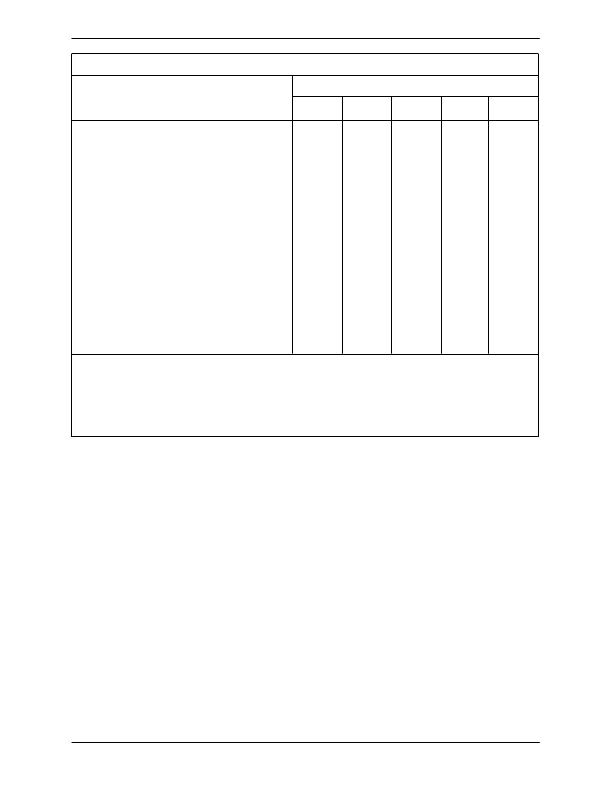
Preventive Maintenance Schedule
Service Interval*
Item
General Condition (Temperature, Unusual
Noises or Vibrations, Cracks, Leaks,
Loose Hardware, Etc.) I
Pump Performance (Gauges, Speed, Flow) I
Bearing Lubrication I R
Seal Lubrication (And Packing Adjustment,
If So Equipped) I R
V‐Belts (If So Equipped) I
Air Release Valve Plunger Rod (If So Equipped) I C
Front Impeller Clearance (Wear Plate) I
Rear Impeller Clearance (Seal Plate) I
Check Valve I
Pressure Relief Valve (If So Equipped) C
Pump and Driver Alignment I
Shaft Deflection I
Bearings I
Bearing Housing I
Piping I
Driver Lubrication - See Mfgr's Literature
Daily Weekly Monthly Semi‐
Annually
Annually
Legend:
I = Inspect, Clean, Adjust, Repair or Replace as Necessary
C = Clean
R = Replace
* Service interval based on an intermittant duty cycle equal to approximately 4000 hours annually.
Adjust schedule as required for lower or higher duty cycles or extreme operating conditions.
TROUBLESHOOTINGPAGE D - 4
Page 18
6500 SERIES OM-06682
PUMP MAINTENANCE AND REPAIR ‐ SECTION E
MAINTENANCE AND REPAIR OF THE WEARING PARTS OF THE PUMP WILL MAINTAIN PEAK
OPERATING PERFORMANCE.
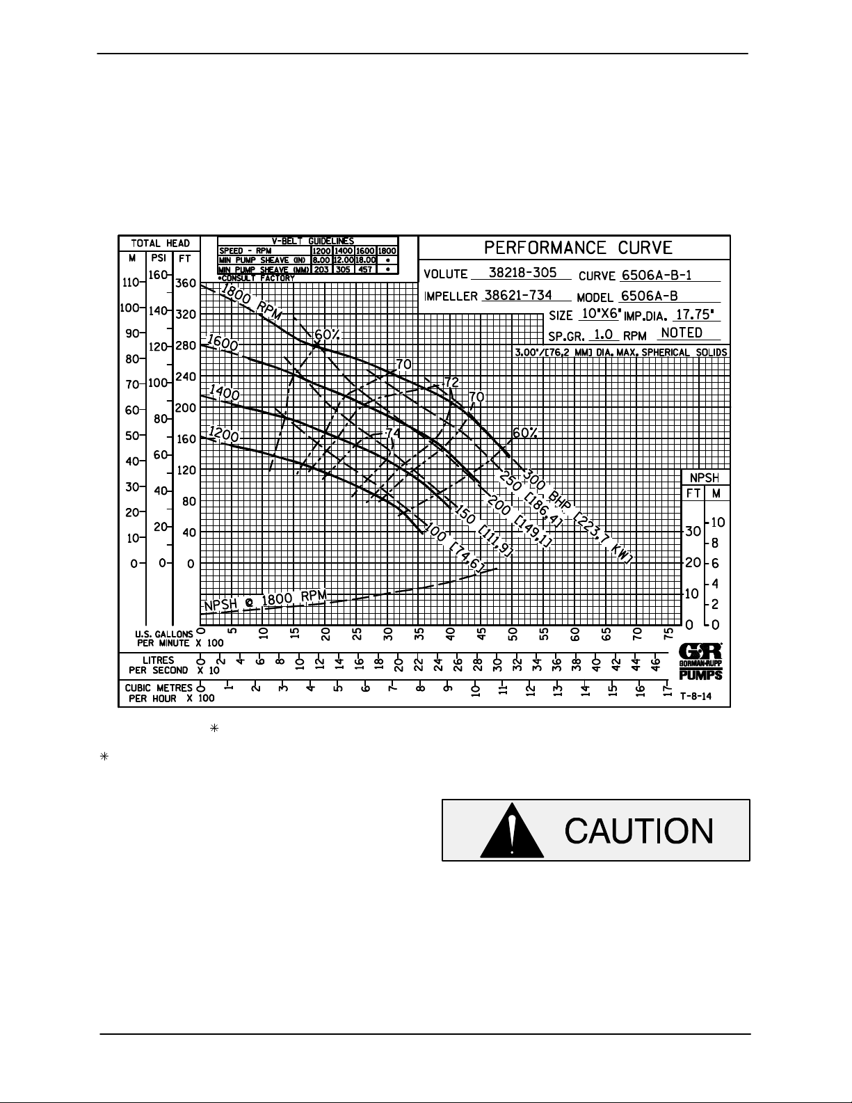
STANDARD PERFORMANCES FOR PUMP MODEL 6506A60-B
Based on 70_F (21_C) clear water at sea level
with minimum suction lift. Since pump installations
are seldom identical, your performance may be dif
ference due to such factors as viscosity, specific
gravity, elevation, temperature, and impeller trim.
Contact the Gorman‐Rupp Company to verify per
formance or part numbers.
Pump speed and operating condition
If your pump serial number is followed by an “N”,
your pump is NOT a standard production model.
MAINTENANCE & REPAIR PAGE E - 1
points must be within the continuous per
formance range shown on the curve.
Page 19
PARTS PAGE
6500 SERIESOM-06682
ILLUSTRATION
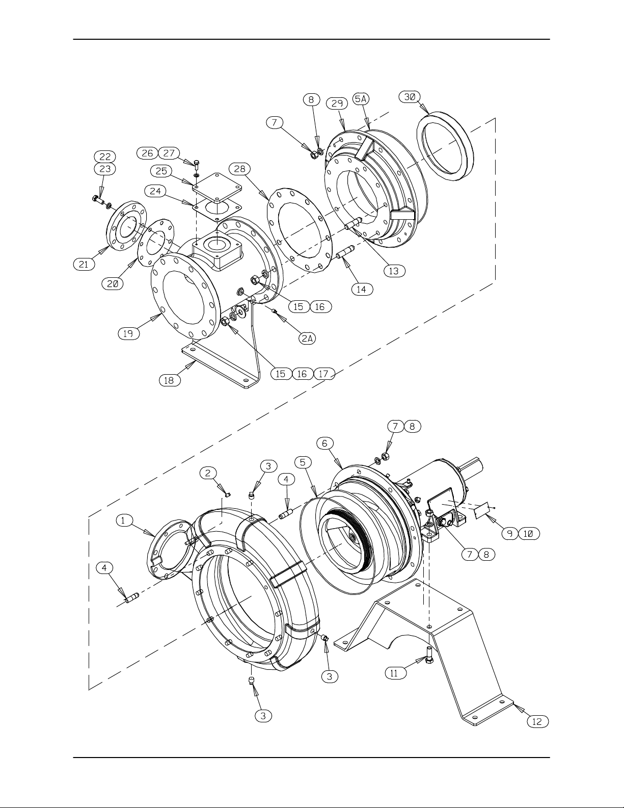
Figure 1. Pump Assembly 6506A60-B
MAINTENANCE & REPAIRPAGE E - 2
Page 20
6500 SERIES OM-06682
PARTS LIST
Pump Assembly 6506A60-B
(From S/N 1594108 Up)
If your pump serial number is followed by an “N”, your pump is NOT a standard production model. Contact
the Gorman‐Rupp Company to verify part numbers.
ITEM
NO.
. 1 PUMP CASING SEE NOTE BELOW 1
. 2 PIPE PLUG P04 15079 1
2A PIPE PLUG P04 15079 1
. 3 PIPE PLUG P08 15079 3
. 4 STUD C1211 15991 20
5
5A
6 REPAIR ROTATING ASSEMBLY 44163-576 1
7 HEX NUT D12 15991 24
8 LOCK WASHER J12 15991 24
9 NAME PLATE 38819-002 13000 1
10 DRIVE SCREW BM#04-03 17000 4
11 HEX HEAD CAP SCREW B1210 15991 4
12 STAND ASSEMBLY 41321-530 24150 1
13 STUD C1414 15991 8
14 STUD C1415 15991 4
15 HEX NUT D14 15991 12
16 LOCK WASHER J14 15991 12
17 FLAT WASHER K14 15991 4
18 STAND 34266-077 15080 1
19 10 X 10 SUCTION SPOOL 38644-807 10000 1
20
21 4" BLIND FLANGE ASSEMBLY 42111-358 1
22 LOCK WASHER J10 15991 8
23 HEX HEAD CAP SCREW B1007 15991 8
24
25 COVER PLATE 33541-045 15080 1
26 LOCK WASHER J08 15991 4
27 HEX HEAD CAP SCREW B0805-1/2 15991 4
28
29 SUCTION HEAD 38246-626 10000 1
30
NOT SHOWN:
PART NAME
O‐RING 25152-387 1
O‐RING 25152-387 1
GASKET 25113-034 1
-WARNING PLATE 2613EV 13990 1
-DRIVE SCREW BM#04-03 17000 4
GASKET 38687-053 19060 1
GASKET 10" 25113-040 1
WEAR RING 38691-373 11010 1
ROTATION DECAL 2613M 1
SUCTION STICKER 6588AG 1
DISCHARGE STICKER 6588BJ 1
G-R DECAL 6" GR-06 1
WARNING DECAL 2613FE 1
LUBE DECAL 11421A 1
OIL LEVEL DECAL 38816-123 1
INSTRUCTION TAG 38817-011 1
PART
NUMBER
QTY
. INCLUDED W/REPAIR PUMP CASING ASSY
46474-362 1
INDICATES PARTS RECOMMENDED FOR STOCK
MAINTENANCE & REPAIR PAGE E - 3
Page 21
ILLUSTRATION
6500 SERIESOM-06682
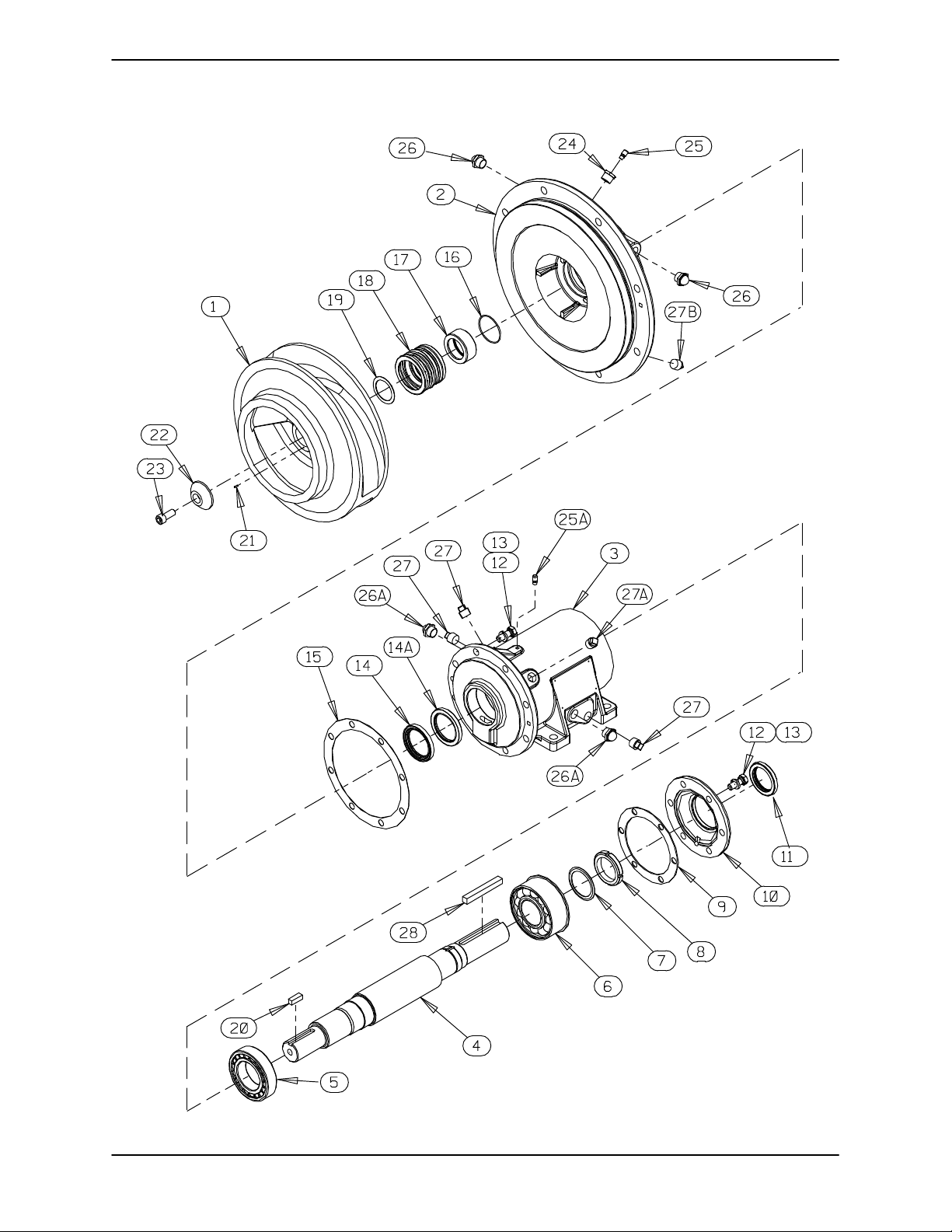
Figure 2. Repair Rotating Assembly
MAINTENANCE & REPAIRPAGE E - 4
Page 22
6500 SERIES OM-06682
PARTS LIST
Repair Rotating Assembly
ITEM
NO.
1 IMPELLER 38621-734 11010 1
2 SEAL PLATE 38272-272 10000 1
3 PEDESTAL 38257-210 10000 1
4 IMPELLER SHAFT 38512-530 16000 1
5 ROLLER BEARING 23535-001 1
6 BEARING 23422-417 1
7 LOCKING TAB COLLAR 23962-515 1
8 BEARING LOCKNUT 23962-015 1
9 BEARING CAP GASKET 38683-664 19060 1
10 BEARING CAP 38322-434 10000 1
11 OIL SEAL 25258-845 1
12 HEX HEAD CAP SCREW B1007 15991 14
13 LOCK WASHER J10 15991 14
14 OIL SEAL 25227-856 1
14A OIL SEAL 25227-856 1
15 GASKET 38683-665 19370 1
16 O‐RING 25152-150 1
17 SHAFT SLEEVE 31163-022 17000 1
18 3.25" MECH SEAL 25285-822 1
19 SHIM SET 48261-033 1
20 KEY N0812 15990 1
21 ROLL PIN S2197 1
22 IMPELLER WASHER 31167-042 17000 1
23 SOCKET HEAD CAP SCREW DM1206 15991 1
24 REDUCER PIPE BUSHING AP1202 15079 1
25 AIR VENT S1530 1
25A AIR VENT S1530 1
26 SEAL CAVITY SIGHT GAUGE S1471 2
26A BEARING CAVITY SIGHT GAUGE S1471 2
27 BEARING CAVITY DRAIN PLUG P12 15079 2
27A PIPE PLUG P12 15079 2
27B SEAL CAVITY PLUG P12 15079 2
28 KEY N1020 15990 1
NOT SHOWN:
PART NAME
SEAL PLATE O‐RING 25152-387 1
SHIPPING PLUG 11495B 15079 2
INSTRUCTION TAG 6588U 1
PART
NUMBER
QTY
INDICATES PARTS RECOMMENDED FOR STOCK
MAINTENANCE & REPAIR PAGE E - 5
Page 23
PUMP AND SEAL DISASSEMBLY AND REASSEMBLY
6500 SERIESOM-06682
Review all SAFETY information in Section A.
Follow the instructions on all tags, label and de
cals attached to the pump.
This pump requires little service due to its rugged,
minimum‐maintenance design. However, if it be
comes necessary to inspect or replace the wearing
parts, follow these instructions which are keyed to
the illustrations (see Figures 1 and 2) and the corre
sponding parts lists.
Some pump service functions may be performed
without separating the pump end assembly from
the engine. However, the following instructions as
sume complete disassembly of the pump is re
quired.
Before attempting to service the pump, lock out or
disconnect the power source and take precautions
to ensure that it will remain inoperative. Close all
valves in the suction and discharge lines and drain
the pump casing by removing the lowermost pipe
plug (33, Figure 1). Clean and reinstall the pipe
plug.
This manual will alert personnel to
known procedures which require spe
cial attention, to those which could
damage equipment, and to those which
could be dangerous to personnel. How
ever, this manual cannot possibly antici
pate and provide detailed instructions
and precautions for every situation that
might occur during maintenance of the
unit. Therefore, it is the responsibility of
the owner/maintenance personnel to
ensure that only safe, established main
tenance procedures are used, and that
any procedures not addressed in this
manual are performed only after estab
lishing that neither personal safety nor
pump integrity are compromised by
such practices.
Before attempting to open or service the
pump:
1. Familiarize yourself with this man
ual.
2. Lock out or disconnect the power
source to ensure that the pump will
remain inoperative.
3. Allow the pump to completely cool
if overheated.
4. Check the temperature and make
sure it is cool before opening any
covers, plates, gauges, or plugs.
5. Close the suction and discharge
valves.
6. Vent the pump slowly and cau
tiously.
7. Drain the pump.
Death or serious personal injury and
damage to the pump or components
can occur if proper lifting procedures
are not observed. Make certain that
hoists, chains, slings or cables are in
good working condition and of suffi
cient capacity and that they are posi
tioned so that loads will be balanced
and the pump or components will not be
damaged when lifting. Suction and dis
charge hoses and piping must be re
moved from the pump before lifting. Lift
the pump or component only as high as
necessary and keep personnel away
from suspended objects.
Use only replacement parts provided or
approved by Gorman‐Rupp. Use of non‐
authorized parts may result in damage to
the equipment and/or injury to personnel
and will invalidate the warranty.
MAINTENANCE & REPAIRPAGE E - 6
Page 24

6500 SERIES
OM-06682
Suction Head and Wear Ring Removal
(Figure 1)
The wear ring (30) is easily accessible and may be
serviced by removing the suction head (29). Before
attempting to service the pump, remove the lower
most pipe plug (3) from the pump casing drain the
pump. Clean and reinstall the drain plug.
It is not necessary to remove the suction spool (19)
from the suction head unless replacement of the
spool, gasket (28) or suction head is required. To
remove the suction spool, disengage the hardware
(15, 16 and 17) and separate the spool and gasket
from the suction head.
To remove the suction head, disengage the hard
ware (7 and 8). Install two 5/8-11 UNC‐2B bolts
(not supplied) in the tapped holes in the suction
head and use the bolts to “push” the suction head
out of the pump casing. Remove the two pusher
bolts.
Remove and discard the O‐ring (5A).
Inspect the wear ring and, if replacement is re
quired, install two 3/4-10 UNC‐2B capscrews (not
supplied) in the tapped holes in the suction head
and use the screws to press the wear ring out of the
suction head.
Pump Casing Removal
Draining Oil From Seal Cavity
(Figure 2)
If any further disassembly is to be performed on the
pump, the seal oil cavity must be drained to pre
vent the oil in the seal cavity from escaping as the
impeller is removed.
Position a clean container under the seal cavity
drain plug (27B). Remove the plug and drain the oil
from the seal cavity into the container. For shorter
drain time, remove one of the pipe plugs (27).
Clean and reinstall the drain plug and air vent. In
spect the oil for water, dirt or a cloudy condition
which could indicate seal failure.
Impeller Removal
(Figure 2)
With the pump casing removed, use an impact
wrench with a hex key to loosen the impeller caps
crew (23). Remove the capscrew, impeller washer
(22) and roll pin (21).
Use a suitable three‐jawed puller to remove the im
peller (1) and key (20) from the shaft (4). Use cau
tion when removing the impeller; tension on the
shaft seal spring will be released as the impeller is
removed.
NOTE
An alternate method of removing the impeller is to
insert a pair of wedges 180_ apart between the im
peller and seal plate (2). Tap the wedges evenly in
an alternating pattern to “walk” the impeller off the
shaft.
(Figure 1)
Remove the uppermost pipe plug (3) from the
pump casing and install a lifting eye in the hole. Be
sure to screw the lifting eye tightly into the hole as
far as it will go. Attach a sling and suitable lifting de
vice to the lifting eye and support the pump casing.
Remove the hardware (7 and 8) and use the lifting
device to pull the pump casing straight away from
the rotating assembly (6). Use caution to ensure
that the pump casing does not fall onto and dam
age the impeller.
Remove and discard the seal plate O‐ring (5).
MAINTENANCE & REPAIR PAGE E - 7
Remove the impeller adjusting shims (19); tie and
tag the shims, or measure and record their thick
ness for ease of reassembly.
Inspect the impeller and replace if cracked or badly
worn.
If no further disassembly is required, refer to Seal
Installation.
Seal Removal
(Figures 1 and 2)
Remove the spring centering washer and seal
spring. Slide the shaft sleeve (17) and rotating por
tion of the seal off the shaft as a unit.
Page 25
6500 SERIESOM-06682
Apply oil to the shaft sleeve and work it up under
the rubber bellows. Slide the rotating portion of the
seal off the shaft sleeve. Remove the shaft sleeve
O‐ring (16).
Use a pair of stiff wires with hooked ends to remove
the stationary element and O‐ring from the seal
plate bore.
An alternate method of removing the stationary
seal components is to remove the hardware (12
and 13) and separate the seal plate and gasket
(15) from the pedestal (13). Position the seal plate
on a flat surface with the impeller side down. Use a
wooden dowel or other suitable tool to press on the
back side of the stationary element until the ele
ment and its O‐ring can be removed.
Separating Rotating Assembly From Power
Source
(Figure 1)
Further disassembly requires separating the rotat
ing assembly from the power source. Remove the
coupling securing the rotating assembly to the
power source and remove the key (28, Figure 2).
Remove the hardware (7, 8 and 11) securing the
rotating assembly to the bearing stand (12) and
use a suitable hoist and sling to move the rotating
assembly to a clean, well‐equipped workshop for
further disassembly.
Remove the pedestal drain plug (27A) and drain
the lubricant. Clean and reinstall the drain plug.
Disengage the hardware (12 and 13) and remove
the bearing cap (10), gasket (9) and oil seal (11).
Use a suitably sized dowel to press the oil seal from
the bearing cap.
Place a block of wood against the impeller end of
the shaft (4) and tap the shaft and assembled bear
ings (5 and 6) from the bearing housing.
Press the oil seals (14 and 14A) from the bearing
housing.
After removing the shaft and bearings, clean and
inspect the bearings in place as follows.
To prevent damage during removal from
the shaft, it is recommended that bearings
be cleaned and inspected in place. It is
strongly recommended that the bearings
be replaced any time the shaft and bear
ings are removed.
Clean the bearing housing, shaft and all compo
nent parts (except the bearings) with a soft cloth
soaked in cleaning solvent. Inspect the parts for
wear or damage and replace as necessary.
Shaft and Bearing Removal and Disassembly
(Figure 2)
When the pump is properly operated and main
tained, the pedestal should not require disassem
bly. Disassemble the shaft and bearings only
when there is evidence of wear or damage.
Shaft and bearing disassembly in the field
is not recommended. These operations
should be performed only in a properly
equipped shop by qualified personnel.
Most cleaning solvents are toxic and
flammable. Use them only in a well ven
tilated area free from excessive heat,
sparks, and flame. Read and follow all
precautions printed on solvent contain
ers.
Clean the bearings thoroughly in fresh cleaning
solvent. Dry the bearings with filtered compressed
air and coat with light oil.
Bearings must be kept free of all dirt and
foreign material. Failure to do so will great
ly shorten bearing life. Do not spin dry
MAINTENANCE & REPAIRPAGE E - 8
Page 26
6500 SERIES
OM-06682
bearings. This may scratch the balls or
races and cause premature bearing fail
ure.
Rotate the bearings by hand to check for rough
ness or binding and inspect the bearing balls. If ro
tation is rough or the bearing balls are discolored,
replace the bearings.
The bearing tolerances provide a tight press fit
onto the shaft and a snug slip fit into the bearing
housing. Replace the bearings, shaft, or bearing
housing if the proper bearing fit is not achieved.
If bearing replacement is required, straighten the
tab on the bearing lock washer (7). Use a spanner
wrench to remove the bearing lock nut (8). Remove
the bearing lock washer.
Use a bearing puller to remove the inboard and
outboard bearings from the shaft.
Shaft and Bearing Reassembly and Installation
(Figure 2)
the oil has been previously used, it must be thor
oughly filtered.
NOTE
Position the outboard bearing (6) on the shaft with
the retaining ring on the bearing O.D. toward the
drive end of the shaft. The inboard bearing (5) is
equipped with a flange ring that is shipped loose
with the bearing. Install the flange ring on the shaft
prior to heating and installing the bearings.
Heat the bearings to a uniform temperature no
higher than 250_F (120_C) and slide the bearings
onto the shaft, one at a time, until they are fully
seated against the shaft shoulders. This should be
done quickly, in one continuous motion, to prevent
the bearings from cooling and sticking on the shaft.
After the bearings have been installed and allowed
to cool, check to ensure that they have not moved
during cooling. If movement has occurred, use a
suitably sized sleeve and a press to reposition the
bearings against the shaft shoulders.
Inspect the shaft (4) for distortion, nicks or
scratches, or for thread damage on the impeller
end. Dress small nicks and burrs with a fine file or
emery cloth. Replace the shaft if defective.
Clean and inspect the bearings as indicated in
Shaft and Bearing Removal and Disassembly.
To prevent damage during removal from
the shaft, it is recommended that bearings
be cleaned and inspected in place. It is
strongly recommended that the bearings
be replaced any time the shaft and bear
ings are removed.
The bearings may be heated to ease installation.
An induction heater, hot oil bath, electric oven, or
hot plate may be used to heat the bearings. Bear
ings should never be heated with a direct flame or
directly on a hot plate.
NOTE
If a hot oil bath is used to heat the bearings, both the
oil and the container must be absolutely clean. If
If heating the bearings is not practical, use a suit
ably sized sleeve and an arbor (or hydraulic) press
to install the bearings on the shaft.
When installing the bearings onto the
shaft, never press or hit against the outer
race, balls, rollers or cage. Press only on
the inner race.
It is recommended that a new bearing lock
washer (7) be installed any time the shaft
and bearings are disassembled. Re‐use of
an old lock washer may create a pre‐load
condition on the bearing, resulting in pre
mature bearing failure.
Install the bearing lockwasher (7) and screw the
bearing locknut (8) onto the shaft until tight. Torque
the bearing lock nut to (150 ft. lbs. (20,8 m. kg.). Af
ter torquing, locate the tab on the lock washer that
MAINTENANCE & REPAIR PAGE E - 9
Page 27
6500 SERIESOM-06682
aligns with a slot in the lock nut and bend the tab
over into the slot.
Apply a light coating of oil to the lip of the inboard oil
seal (14A) and press it into the pedestal bore with
the lip positioned as shown in Figure 2. Press the
oil seal into the pedestal until the face is just flush
with the machined surface on the inside of the ped
estal.
It is recommended that a sleeve be positioned
against the inboard oil seal to prevent the lip of the
oil seal from rolling as the shaft and bearings are
installed in the pedestal. The O.D. of the sleeve
should be just smaller than the bearing housing
bore, while the I.D. of the sleeve should be just larg
er than the O.D. of the lip seal area of the shaft.
With the oil seal sleeve in place, lubricate the lip
seal area of the shaft and slide the shaft and as
sembled bearings into the bearing housing until
the retaining ring on the outboard bearing seats
against the pedestal. Remove the oil seal sleeve.
(15 m. kg.), going around the bolt circle 1‐1/2
times.
Lubricate the bearings as indicated in LUBRICA
TION at the end of this section.
Securing Rotating Assembly to Power Source
(Figure 1)
Install the drive key (28, Figure 2) in the shaft key
way.
Reinstall the drive coupling on the impeller shaft.
Using a suitable lifting device, position the rotating
assembly on the bearing stand (12) and secure it
with the previously removed hardware (7, 8 and
11). Align the coupling as described in Installa
tion, Section B.
Seal Reassembly and Installation
(Figures 2 and 3)
When installing the shaft and bearings into
the bearing bore, push against the outer
race. Never hit the balls, rollers or cages.
Apply a light coating of oil to the lip of the outboard
oil seal (14) and press it into the pedestal with the
lip positioned as shown in Figure 2. The face of the
oil seal should be just flush with the outer face of
the pedestal.
Apply a light coating of oil to the lip of the oil seal
(11) and press it into the bearing cap (10) with the
lip positioned as shown in Figure 2. The oil seal
should be centered in the bearing cap.
Install the gasket (9) and slide the assembled bear
ing cap and oil seal over the impeller shaft. Use
caution not to cut or roll the lip of the oil seal (11) on
the shaft keyway.
Apply “Loctite Threadlocker No. 242” or equivalent
compound to the capscrews (12) and secure the
bearing cap to the pedestal with the hardware (12
and 13). Torque the capscrews (12) in an alternat
ing pattern to 80 ft. lbs. (11 m. kg.). Torque the cap
screws again in an alternating pattern to 110 ft. lbs.
Most cleaning solvents are toxic and
flammable. Use them only in a well ven
tilated area free from excessive heat,
sparks, and flame. Read and follow all
precautions printed on solvent contain
ers.
Clean the seal cavity and shaft with a cloth soaked
in fresh cleaning solvent. Inspect the stationary
seat bore in the seal plate for dirt, nicks and burrs,
and remove any that exist. The stationary seat bore
must be completely clean before installing the
seal.
A new seal assembly should be installed
any time the old seal is removed from the
pump. Wear patterns on the finished faces
cannot be realigned during reassembly.
Reusing an old seal could result in prema
ture failure.
To ease installation of the seal, lubricate the shaft
sleeve O‐ring and the stationary element O‐ring
with “P-80R Emulsion” or water. Do not use oil or
any substitute lubricant other than water. See Fig
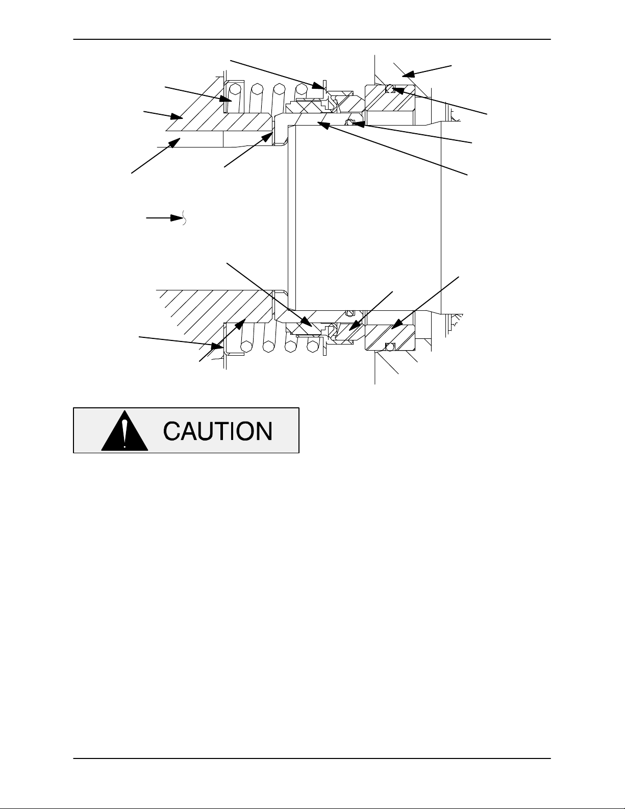
ure 8 for seal part identification.
MAINTENANCE & REPAIRPAGE E - 10
Page 28
6500 SERIES
OM-06682
SPRING
IMPELLER
SHAFT
KEY
IMPELLER
SHAFT
SPRING
CENTERING
WASHER
RETAINER
IMPELLER
SHIMS
BELLOWS
ROTATING
ELEMENT
SEAL PLATE
O‐RING
SLEEVE
O‐RING
SHAFT
SLEEVE
STATIONARY
ELEMENT
Figure 8. Seal Assembly
This seal is not designed for operation at
temperatures above 160_F (71_C). Do not
use at higher operating temperatures.
If the seal plate was removed, install the seal plate
gasket (15). Position the seal plate over the shaft
and secure it to the bearing housing with the hard
ware (12 and 13).
Press the stationary element and its O‐ring into the
seal plate until fully seated in the seal plate bore. A
push tube cut from a length of plastic pipe would
aid this process. The I.D. of the tube should be
slightly larger than the O.D. of the shaft sleeve (17).
Install the shaft sleeve O‐ring (16) in the groove in
the I.D. of the sleeve. Lubricate the O‐ring and the
O.D. of the shaft sleeve with “P-80R Emulsion” or
water. Do not use oil or any substitute lubricant
other than water.
Slide the rotating subassembly (consisting of the
rotating element, retainer and bellows) onto the
sleeve until the rotating element is just flush with
the chamfered end of the sleeve. Slide the shaft
sleeve and rotating subassembly onto the shaft
until the seal faces contact and the shaft sleeve
seats against the shoulder on the impeller shaft.
Install the seal spring and spring centering washer.
Lubricate the seal assembly as indicated in
LUBRICATION, after the impeller has been in
stalled.
Impeller Installation and Adjustment
(Figure 2)
Inspect the impeller (1) and replace it if cracked or
badly worn.
Install the same thickness of adjusting shims (19)
as previously installed. Install the impeller key (20)
in the shaft keyway. Align the keyway in the impel
ler with the shaft key and press the impeller onto
the shaft until fully seated.
A clearance of .025 to .040 inch (0,64 to 1,02 mm)
between the impeller and the seal plate is neces
sary for maximum pump efficiency. Measure this
clearance and add or remove impeller adjusting
shims as required.
MAINTENANCE & REPAIR PAGE E - 11
Page 29
6500 SERIESOM-06682
Apply `Loctite Retaining Compound No. 242' or
equivalent to the threads of the impeller capscrew
(23). Install the roll pin (21) in the hole in the impel
ler. Position the impeller washer over the end of the
impeller shaft so the hole in the washer aligns with
the roll pin. Block impeller rotation as described in
Impeller Removal and torque the impeller caps
crew to 250 ft. lbs. (34,6 m. kg.).
Pump Casing Installation
(Figure 1)
Lubricate the O‐ring (5) with light grease and install
it in the groove in the O.D. of the seal plate (2, Fig
ure 2). Install a lifting eye in the uppermost hole in
the pump casing (1) for the pipe plug (3). Be sure to
screw the lifting eye tightly into the hole as far as it
will go. Attach a sling and suitable lifting device to
the lifting eye and use the lifting device to position
the pump casing over the rotating assembly. Install
the hardware (7 and 8) on the studs (4) and use the
hardware to fully seat the pump casing against the
seal plate. Remove the lifting eye and reinstall the
pipe plug.
Suction Head and Wear Ring Installation
(Figure 1)
If the wear ring (30) was removed, position the re
placement wear ring in the suction head (29) and
use an arbor (or hydraulic) press to press it into the
suction head until fully seated.
ounces (5 liters) of SAE No. 30 non‐detergent oil to
the center of the sight gauges (26). Clean and rein
stall the vented plug. Check the oil level regularly
and maintain it at the middle of the sight gauge.
Bearings
(Figure 2)
The bearing housing was fully lubricated when
shipped from the factory. Check the oil level regu
larly through the sight gauges (26A) and maintain it
at the midpoint of the gauges. When lubrication is
required, remove the pipe plugs (27A) and add
SAE No. 30 non‐detergent oil through one of the
openings. When lubricating a dry (overhauled) in
termediate, fill the bearing cavity with approximate
ly 50 ounces (1,5 liters). Clean and reinstall the
pipe plugs. Do not over‐lubricate. Over‐lubrication
can cause the bearings to over‐heat, resulting in
premature bearing failure.
Under normal conditions, drain the bearing hous
ing once each year and refill with clean oil. Change
the oil more frequently if the pump is operated con
tinuously or installed in an environment with rapid
temperature change.
Install the O‐ring (5A) in the groove in the O.D. of
the suction head and lubricate it with light grease.
Position the suction head over the studs (4) and
use the hardware (7 and 8) to seat the suction head
in the pump casing (1).
If the suction spool (19) was removed, install a new
gasket (28) and secure the spool to the suction
head with the previously removed hardware (15,
16 and 17).
LUBRICATION
Seal Assembly
(Figure 2)
Before starting the pump, remove the air vent (25)
and fill the seal cavity with approximately 170
Monitor the condition of the bearing lubri
cant regularly for evidence of rust or mois
ture condensation. This is especially im
portant in areas where variable hot and
cold temperatures are common.
For cold weather operation, consult the factory or a
lubricant supplier for the recommended grade of
oil.
Power Source
Consult the literature supplied with the power
source, or contact your local power source repre
sentative.
MAINTENANCE & REPAIRPAGE E - 12
Page 30

For Warranty Information, Please Visit
www.grpumps.com/warranty
or call:
U.S.: 419-755-1280
Canada: 519-631-2870
International: +1-419-755-1352
GORMAN‐RUPP PUMPS
 Loading...