

Gorman-Rupp Pumps 4D-X3 User Manual
ACU
OM-01515---OM02
April 28, 1997
INSTALLATION, OPERATION,
AND MAINTENANCE MANUAL
WITH PARTS LIST
DIAPHRAGM PUMPS
MODEL
4D---X3 1P
THE GORMAN-RUPP COMPANY D MANSFIELD, OHIO
GORMAN-RUPP OF CANADA LIMITED D ST. THOMAS, ONTARIO, CANADA Printed in U.S.A.
www.gormanrupp.com
eCopyright by the Gorman-Rupp Company

TABLE OF CONTENTS
INTRODUCTION PAGE I --- 1...................................................
WARN ING S - SE CTI ON A PA G E A --- 1.........................................
IN STA L LAT ION --- S EC T IO N B PA G E B --- 1.....................................
Pump Dimensions PAGE B --- 1........................................................
PREINSTALLATION INSPECTION PAGE B --- 1...............................................
POSITIONING PUMP PA GE B --- 2..........................................................
Lifting PA GE B --- 2....................................................................
Mounting PA GE B --- 2................................................................
SUCTION AND DISCHARGE PIPING PAGE B --- 2............................................
Materials PA GE B --- 2.................................................................
Line Configuration PAGE B --- 2.........................................................
Fixed, Rigid Piping P AGE B --- 2........................................................
Gauges PA GE B --- 3..................................................................
SUCTION LINES PAGE B --- 3..............................................................
Fittings PA GE B --- 3..................................................................
Strainers PA GE B --- 4.................................................................
Sealing PAGE B --- 4..................................................................
DISCHARGE LINES PA GE B --- 4...........................................................
Valves PA GE B --- 4...................................................................
ALIGNMENT PAGE B --- 4.................................................................
ELECTRICAL CONNECTIONS PAGE B --- 5..................................................
OPER AT IO N --- SEC T IO N C PA G E C --- 1.......................................
STARTING PA GE C --- 1...................................................................
OPERATION PA GE C --- 1.................................................................
Priming PA GE C --- 1..................................................................
OPERATION CHECKS PA GE C --- 1.........................................................
Gearbox Check PAGE C --- 1...........................................................
Leakage Check PAGE C --- 1...........................................................
Strainer Check PAGE C --- 2............................................................
Accumulator Chamber Check PAGE C --- 2..............................................
STOPPING PA GE C --- 2...................................................................
Cold Weather Preservation PAGE C --- 2.................................................
GEARBOX TEMPERATURE CHECK PAGE C --- 2.............................................
TR OUB LES HOO TI NG --- SE C TI ON D PA G E D --- 1...............................
PUMP MAINTENANCE AND REPAIR - SECTION E PAGE E --- 1..................
STANDARD PERFORMANCE CHART PAGE E --- 1...........................................
PARTS LISTS:
Pump Model PA GE E --- 3.............................................................
Diaphragm Pot Assembly PAGE E --- 5..................................................
Plunger Rod Assembly PAGE E --- 7....................................................
Gearbox Assembly PAGE E --- 9........................................................
i

TABLE OF CONTENTS
(continued)
PUMP AND SEAL DISASSEMBLY AND REASSEMBLY PAGE E --- 10...........................
Suction And Discharge Check Valve Removal PAGE E --- 10...............................
Diaphragm Removal PAGE E --- 10......................................................
Plunger Rod Removal And Disassembly PAGE E --- 11....................................
Gearbox Removal And Disassembly PAGE E --- 11........................................
Gearbox Reassembly And Installation P AGE E --- 12......................................
Plunger Rod Reassembly And Installation PAGE E --- 14...................................
Diaphragm Installation PAGE E --- 15....................................................
Suction And Discharge Check Valve Installation PAGE E --- 15.............................
LUBRICATION PA GE E --- 15...............................................................
Plunger Rod Assembly PAGE E --- 15...................................................
Gearbox PA GE E --- 15................................................................
Motor PAGE E --- 16...................................................................
ii
DSERIES
OM--01515
INTRODUCTION
Thank You for purchasing a Gorman-Rupp pump.
Read this manual carefully to learn how to safely
install and operate your pump. Failure to do so
could result in personal injury or damage to the
pump.
This Installation, Operation, and Maintenance
manual is designed to help you achieve the best
performance and longest life from your GormanRupp pump.
This is a DSeries, positive displacementpumputilizing a single-action diaphragm to produce a
straight-through flow of liquid. The pump is provided with an explosion-proof electric motor and
ideallysuitedto industrialand contractor’s applications since it will handle liquids ranging from clear
water to construction-site muck. The basic material of construction for w etted parts is aluminum,
with neoprene flap valves and diaphragm.
If there are any questions regarding the pump or
its application which are not covered in this manual or in other literature accompanying this unit,
please contact your Gorman-Rupp distributor, or
write:
The Gorman-Rupp Company
P.O. Box 1217
Mansfield, Ohio 44901--1217
Phone: (419) 755--1011
or
Gorman-Rupp of Canada Limited
70 Burwell Road
St. Thomas, Ontario N5P 3R7
Phone: (519) 631--2870
Because pump installations are seldom identical,
this manual cannot possibly provide detailed instructions and precautions for every aspect of
each specific application. Therefore, it is the responsibility of the owner/installer of the pump to
ensure that applications not addressed in this
manual are performed only after establishing that
neither operator safety norpump integrity are com-
promised by the installation. Pumps and related
equipment must be installed and operated ac-
cording to all national, local and industry standards.
The following are used to alert maintenance personnel toprocedures which require specialattention, tothose which coulddamage equipment,and
to those which could be dangerous to personnel:
Immediate hazards whichWILL resultin
severe personal injury or death. These
instructions describe the procedure required and the injury which will result
from failure to follow the procedure.
Hazards or unsafe practices which
COULDresult in severe personal injury
or death. These instructions describe
the procedure required and the injury
which could result from failure to follow
the procedure.
HazardsorunsafepracticeswhichCOULD
result in minor personal injury or product
or property damage. These instructions
describe the requirements and the possibledamage which couldresult from failure
to follow the procedure.
NOTE
Instructions to aid in installation, operation,and
maintenance, or which clarify a procedure.
PAGE I -- 1INTRODUCTION
DSERIES
SAFETY - SECTION A
This information applies to D Series
electric motor driven diaphragm
pumps. Refer to the manual accompanying the motor before attempting to
begin operation.
Because pump installations are seldom
identical, this manual cannot possibly
provide detailed instructions and precautions for each specific application.
Therefore, it is the owner/installer’s responsibility to ensure that applications
not addressed in this manual are performed only after establishing that neither operator safety nor pump integrity
are compromised by the installation.
Beforeattempting toopenorservic e the
pump:
OM--01515
Afterthe pump hasbeeninstalled,block
the wheels and secure the pump to prevent creeping. Make certain that the
pump and all piping or hose connections are tight, properly supported and
secure before operation.
Donot operate the pump without the eccentric and coupling guards in place
over the rotating parts. Exposed rotating parts can catch clothing, fingers,or
tools, causing severe injury to personnel.
1. Familiarize yourself with this manual.
2. Lock out incoming power to the
motor to ensure that the pump will
remain inoperative.
3. Allow the pump to completely cool
if overheated.
4. Close the discharge valve (if
used).
5. Drain the pump.
This pump is designed to handle non volatile non-flammable liqui ds containing specified entrained solids. Do not
attempt to pump volatile, corrosive, or
flammable liquids which may damage
the pump or endanger personnel as a
result of pump failure.
The gearbox provided on this pump is
designed for operation at 1750 RPM
maximum input speed. If operated at a
higher RPM, pump componentsmay be
destroyed.
Install and operate only an explosion
proof motor in an explosive atmosphere. Install, connect, and operate
the motor in accordance with the National Electric Code and all local codes.
Ifthere is a conflict between the instructions in the manual accompanying the
unit and the National Electric Code or
the applicable local code, the National
or local code shall take precedence.
PAGE A -- 1SAFETY

The electrical power used to operate
this pump is high enough to cause inju ry or death. Obtain the services of a qualified electrician to make all electrical
connections. make certain that the
pump and motor are properly
grounded; never use gas pipe as an
electrical ground. Be sure that the incoming power matches the voltage and
phase of the pump and motor before
connecting the power source. Do not
run the pump if the v oltage is not within
the limits.
Allelectrical connectionsmustbe in accordance with the National Electric
Code. If there is a conflict between the
instructions provided and N.E.C.speci-
DSERIESOM--01515
fications, N.E.C. specifications shall
take precedence. All electrical equipment supplied with this pump was in
conformance with N.E.C. requirements
in effect on the date of manufacture.
Failure to follow applicable specifications, or substitution of electrical parts
not supplied or approved by the manufacturer, can result in severe injury or
death.
Never install a positive shut-off valve in the
discharge line; discharge restrictions will
cause excessive friction loss resulting in
overloading and destruction of pump and
drive components. It is strongly recommended that unless absolutelynecessary,
nopositive shut-offvalve be installed in the
suction line; excessive restriction will
cause incomplete filling of the diaphragm
chamber and result in shortened diaphragm life.
PAGE A -- 2
SAFETY
DSERIES OM--01515
INSTALLATION --- SECTION B
Review all SAFETY information in Section A.
Since pump installations areseldom identical,this
section offers only general recommendations and
practices required to inspect, position, and arrange the pump and piping.
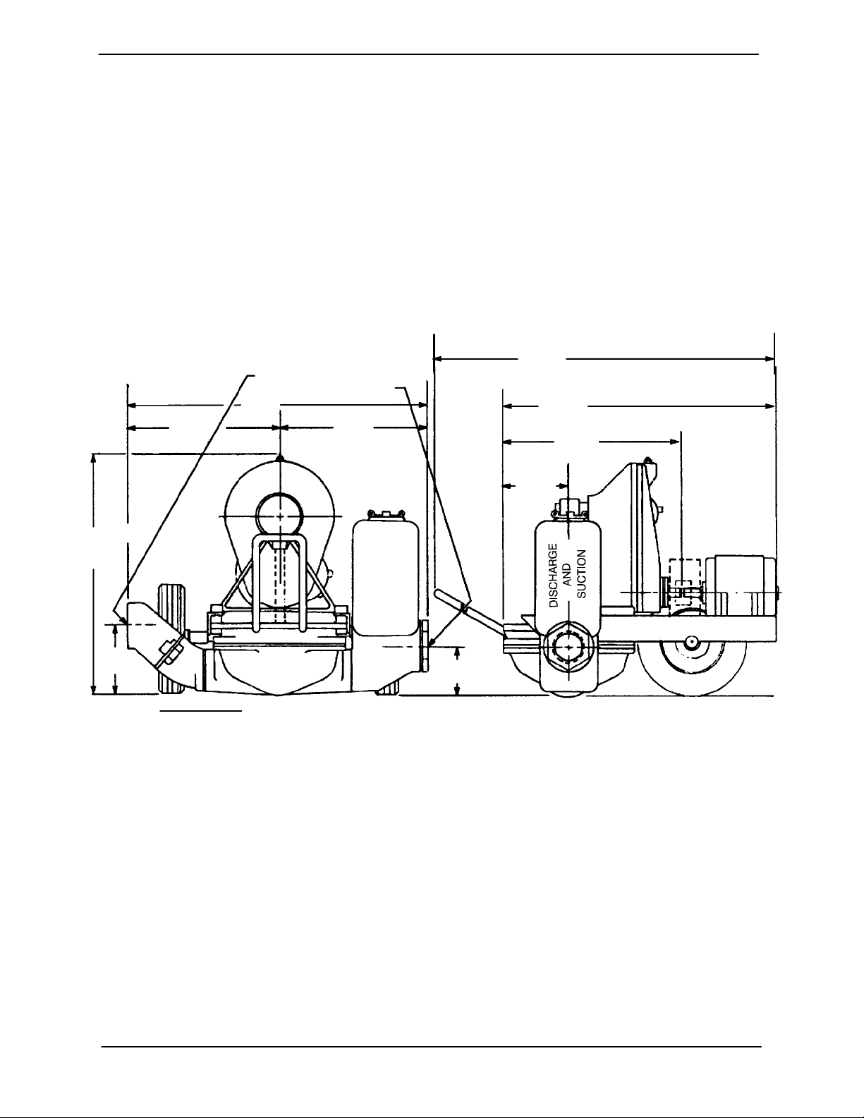
OUTLINE DRAWING
4” N.P.T. DISCHARGE
3” (OR 4”) N.P.T. SUCTION
33.88
[860,6]
17.00
[431,8]
APPROX
26.62
[676,1]
16.88
[428,8]
Forfurtherassistance,contact yourGorman-Rupp
distributor or t he Gorman-Rupp Company.
Pump Dimensions
SeeFigure1fortheapproximatephysicaldimensionsofthispump.
50.69
[1287,5]
[1370,1]
[185,7]
MOTOR FRAME 182T AND 184T
53.94
MOTOR FRAME 213 AND 215
32,31
MOTOR FRAME 182T AND 184T
[820,7]
34,94
MOTOR FRAME 213 AND 215
[887,5]
19.69
[500,1]
7.31
7.00
[177,8]
DIMENSIONS:
INCHES
[MILLIMETERS]
Figure 1. 4D Electric Motor Driven Pumps
PREINSTALLATION INSPECTION
Thepump assembly wasinspected and tested before shipment from the factory. Before installation,
inspect the pump fordamage which may have occurred during shipment. Check as follows:
a. Inspectthe pumpforcracks, dents, damaged
threads, and other obvious damage.
b. Check for and tighten loose attaching hard-
ware. Since gaskets tend to shrink after drying, check for loose hardware at mating surfaces.
5,31
[134,9]
c. Carefully read all tags, decals, and markings
onthepump assembly,and performallduties
indicated.
d. Check levels and lubricate as necessary. Re-
fer to LUBRICATION in the MAINTENANCE
AND REPAIR section of this manual and perform duties as instructed.
e. If the pump and motor have been stored for
more than 12 months, some of the components or lubricants may have exceeded their
maximumshelflife.Thesemustbeinspected
PAGE B -- 1INSTALLATION
OM--01515 DSERIES
or replaced to ensure maximum pump serv-
ice.
If the maximum shelf life has been exceeded, or if
anything appears to be abnormal, contact your
Gorman-Rupp distributor or the factory to determine the repair or updating policy. Do not put the
pump into service until appropriate action has
been taken.
POSITIONING PUMP
Lifting
This pump is designed to be easily positioned for
operationusing the drawbar and wheels. The total
pump weight is approximately 370 pounds (167,8
kg), not includingaccessories.Customer installed
equipment such as suction and discharge piping
must be removed before attempting to lift.
Thepumpassemblycanbeseriously
damaged ifthe cables or chains used to lift
and move theunit are improperlywrapped
around the pump.
Mounting
Locatethepumpinanaccessibleplaceascloseas
practicalto the liquid being pumped. Levelmounting is essential for proper operation.
The pump may have to be supported or shimmed
to provide for level operation or to eliminate vibration.
After the pump has been positioned, block the
wheels and secure the pump t o prevent creeping.
SUCTION AND DISCHARGE PIPING
Materials
Either pipe or hose maybe used for suction and
discharge lines; however, the materials must be
compatiblewiththeliquidbeingpumped.If hose is
used in suction lines, it must be the rigid-wall, reinforced type to prevent collapse under suction. Using piping couplings in suction lines is not recommended.
Line Configuration
Keep suction and discharge lines as straight as
possible to minimize friction losses. Make minimum use of elbows and fittings, which substantiallyincreasefrictionloss.Ifelbowsarenecessary,
use the long-radius type to minimize friction loss.
Never pull a line into place by tightening connec tionsatthe pump.Lines near thepump mustbe independently supported to avoid strain on the
pump which could cause excessive vibration and
increased diaphragm and gear train wear. If hosetype lines are used, they should have adequate
support to secure them when filled with liquid and
under pressure.
Fixed, Rigid Piping
This pump is equipped with an integral suction accumulator chamber which promotes an efficient
flow of liquid and acts as an air cushion against
shock. Since the air in this chamber will leak away
during pump operation, the air must be replenished periodically. To introduce air into the chamber, stop the pump and remove the suction accumulator plug and integral gasket; this will break
prime and allow the liquid in the chamber to drain
away through the suction line.
If the pump is mounted in a system with fixed,rigid
piping, it is recommended that a flexible connectionbeinstalledatornearthesuctionanddischarge ports to absorb shock which would otherwise be transmitted through the drive train and
greatly accelerate pump wear.
Pump performance is adversely effected by increased suction lift, discharge elevation, and friction losses. See Page E-1 to be sure your overall
application allows the pump to operate within the
safe operation range.
PAGE B -- 2 INSTALLATION
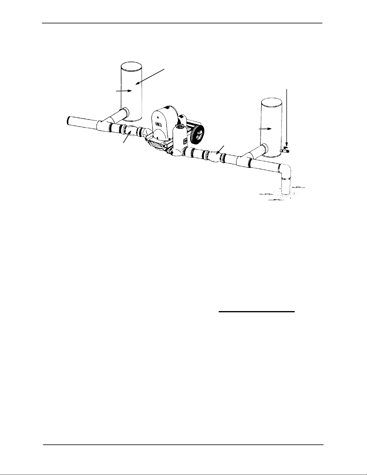
In a fixed piping installation, properly sized surge
suppressorsmust be installed in both suction and
discharge lines. If commercial surge suppressors
are not readily available, air chambers may be fabricated from pipe as shown in Figure 2.
DSERIES OM--01515
AIR CHAMBERS
(18TO24INCHLENGTHSOF
6 TO 8 INCH DIAMETER PIPE
WITH WELDED CAPS)
DISCHARGE
CHAMBER
DISCHARGE
FLEXIBLE JOINT
FLEXIBLE JOINT
1/2-INCH VALVE FOR
RECHARGING AIR
CHAMBER WITH
COMPRESSED AIR
(ALSO ON DISCHARGE
CHAMBER)
SUCTION
CHAMBER
NOTE: INSTALL AIR CHAMBERS OFF FLOW LINE TEES
TO AVOID SURFACE TURBULENCE WITHIN CHAMBERS.
Figure 2. Fixed Piping Installation
Notethat the airchambers have not been installed
directly in the flow line, but have been installed off
tees to avoid turbulence within the chambers. The
airchambersarefittedwithvalvestopermitintroductionof small amounts of compressed air to further dampen shock; this compressed air will leak
away during operation, and should be replaced
from time to time. If the suction chamber floods,
open the suction chamber valve to break prime
and allow the liquid in chamber to drain through
the suction line.
Gauges
Ifdischarge pressure and vacuum suction gauges
aredesired, drilland tapthesuctionanddischarge
lines not less than 18 inches (457,2 mm) from the
suction and discharge ports and install the lines.
Installationcloserto the pump may result in erratic
readings.
SUCTION
the source of the liquid being pumped; if the line
slopes down to the pump at any point along the
suction run, air pockets will be created.
NOTE
Maximumpumpperformanceis realized atsuction
liftsof 5feet(1,5 m)or less. Usetheshortestpossible length of suction hose or piping; lengths of 25
feet(7,6m)orlonger will reducethecapacityofthe
pump.
It is strongly recommended that no positive shutoff valve be installed in the suction line; excessive
restrictions will cause incomplete filling of the diaphragm chamber and result in short diaphragm
life.
Fittings
SUCTION LINES
To avoidairpockets whichcould affect pumppriming, the suction line must be as short and direct as
possible.Whenoperationinvolvesasuctionlift,the
line must always slope upward to the pump from
Suction lines should bethesame sizeas the pump
inlet. If reducers are used in s uction lines, they
should be the eccentric type, and should be installedwith the flat part ofthe reducers uppermost
to avoid creating air pockets. The suction line
shouldnotberestrictedmorethan 1inchbelowthe
nominal suction size.
PAGE B -- 3INSTALLATION
OM--01515 DSERIES
The use of pipe couplings in the suction line is not
recommended.
Strainers
If a strainer is furnished with the pump, be certain
touseit; any sphericalsolidswhichpass througha
strainer furnished with the pump will also pass
through the pump itself.
If a strainer is not furnished with the pump, but is
installed by the pump user, make certain that the
total area of the openings in the strainer is at least
three or four times the cross section of the suction
line,and that the openings will not permit passage
of solids larger than the solids handling capability
of the pump.
This pump is designed to handle up to 2-1/4 inch
(57 mm) diameter spherical solids.
Sealing
Since even a slight leak will affect priming, head,
and capacity, especially when operating with a
high suction lift, all connections in the suction line
should be sealed with pipe dope to ensure an airtight seal. Follow the sealant manufacturer’s recommendations when selecting and applying the
pipe dope. The pipe dope should be compatible
with the liquid being pumped.
DISCHARGE LINES
Never install a positive shut-off valve in the
discharge line; discharge restrictions will
cause excessive friction loss resulting in
overloading and destruction of pump and
drive components. It is strongly recommended that unless absolutelynecessary,
nopositive shut-offvalve be installed in the
suction line; excessive restriction will
cause incomplete filling of the diaphragm
chamber and result in shortened diaphragm life.
ALIGNMENT
Beforeattempting toopenorservice the
pump:
1. Familiarize yourself with this manual.
2. Shutoffincoming power to the motorand lock itouttoensurethat the
pump will remain inoperative.
3. Allow the pump to completely cool
if overheated.
4. Close the discharge valve (if
used).
5. Drain the pump.
Thedischargelinemustbethesamesize
as,orlargerthan,thesuctionline. Neverinstall or operate the pump with a discharge
line smaller than the suction; a restricted
dischargeline will cause excessive friction
loss resulting in overloading and destruction of pump and drive components.
Valves
Thepumpisprovidedwithintegralsuctionanddischarge check valves.
PAGE B -- 4 INSTALLATION
It is imperative that alignment be checked
before the pump is operated.
The pump and motor were alignedand secured at
thefactory, butfastening hardw are may have loosened during shipment. It is imperative that this
hardware and the alignment be checked after the
pump is installed and before operation. Adjustments may be made by loosening the securing
hardware and shifting or shimming components
as required.
Tocheck couplingalignment,use afeelergaugeor
taper gauge between the coupling halves every
 Loading...