

GORMAN-RUPP PUMPS D Series, 4D-E3 3P Installation, Operation, And Maintenance Manual With Parts List
Page 1
OM‐01510-OM03
June 29, 1981
Rev. E 12/05/18
Supersedes: OM-03569
INSTALLATION, OPERATION,
AND MAINTENANCE MANUAL
WITH PARTS LIST
D SERIES PUMPS
MODEL
4D-E3 3P
GORMAN‐RUPP PUMPS
www.grpumps.com
e1981 Gorman‐Rupp Pumps Printed in U.S.A.
Page 2

TABLE OF CONTENTS
INTRODUCTION PAGE I - 1...................................................
WARNINGS SECTION A PAGE A - 1........................................
INSTALLATION - SECTION B PAGE B - 1.....................................
Pump Dimensions PAGE B - 1........................................................
PREINSTALLATION INSPECTION PAGE B - 1...............................................
POSITIONING PUMP PAGE B - 2..........................................................
Lifting PAGE B - 2....................................................................
Mounting PAGE B - 2................................................................
SUCTION AND DISCHARGE PIPING PAGE B - 2............................................
Materials PAGE B - 2.................................................................
Line Configuration PAGE B - 2.........................................................
Fixed, Rigid Piping PAGE B - 2........................................................
Gauges PAGE B - 3..................................................................
SUCTION LINES PAGE B - 3..............................................................
Fittings PAGE B - 3..................................................................
Strainers PAGE B - 4.................................................................
Sealing PAGE B - 4..................................................................
DISCHARGE LINES PAGE B - 4...........................................................
Valves PAGE B - 4...................................................................
ALIGNMENT PAGE B - 4.................................................................
ELECTRICAL CONNECTIONS PAGE B - 5..................................................
OPERATION - SECTION C PAGE C - 1.......................................
STARTING PAGE C - 1...................................................................
OPERATION PAGE C - 1.................................................................
Priming PAGE C - 1..................................................................
OPERATION CHECKS PAGE C - 1.........................................................
Gearbox Check PAGE C - 1...........................................................
Leakage Check PAGE C - 1...........................................................
Strainer Check PAGE C - 2............................................................
Accumulator Chamber Check PAGE C - 2..............................................
STOPPING PAGE C - 2...................................................................
Cold Weather Preservation PAGE C - 2.................................................
GEARBOX TEMPERATURE CHECK PAGE C - 2.............................................
TROUBLESHOOTING - SECTION D PAGE D - 1...............................
PUMP MAINTENANCE AND REPAIR SECTION E PAGE E - 1..................
STANDARD PERFORMANCE CHART PAGE E - 1...........................................
PARTS LISTS:
Pump Model PAGE E - 3.............................................................
Diaphragm Pot Assembly PAGE E - 5..................................................
Plunger Rod Assembly PAGE E - 7....................................................
Gearbox Assembly PAGE E - 9........................................................
i
Page 3

TABLE OF CONTENTS
(continued)
PUMP AND SEAL DISASSEMBLY AND REASSEMBLY PAGE E - 10...........................
Suction And Discharge Check Valve Removal PAGE E - 10...............................
Diaphragm Removal PAGE E - 10......................................................
Plunger Rod Removal And Disassembly PAGE E - 11....................................
Gearbox Removal And Disassembly PAGE E - 11........................................
Gearbox Reassembly And Installation PAGE E - 12......................................
Plunger Rod Reassembly And Installation PAGE E - 14...................................
Diaphragm Installation PAGE E - 15....................................................
Suction And Discharge Check Valve Installation PAGE E - 15.............................
LUBRICATION PAGE E - 15...............................................................
Plunger Rod Assembly PAGE E - 15...................................................
Gearbox PAGE E - 15................................................................
Motor PAGE E - 16...................................................................
ii
Page 4
D SERIES
OM-01510
INTRODUCTION
This Installation, Operation, and Maintenance
manual is designed to help you achieve the best
performance and longest life from your Gorman‐
Rupp pump.
This is a D Series, positive displacement pump util
izing a single‐action diaphragm to produce a
straight‐through flow of liquid. The pump is ideally
suited to industrial and contractor's applications
since it will handle liquids ranging from clear water
to construction‐site muck. The basic material of
construction for wetted parts is aluminum, with
neoprene flap valves and diaphragm.
If there are any questions regarding the pump or
its application which are not covered in this man
ual or in other literature accompanying this unit,
please contact your Gorman‐Rupp distributor, or
write:
The Gorman‐Rupp Company
P.O. Box 1217
Mansfield, Ohio 44901-1217
or
Gorman‐Rupp of Canada Limited
70 Burwell Road
St. Thomas, Ontario N5P 3R7
The following are used to alert maintenance per
sonnel to procedures which require special atten
tion, to those which could damage equipment, and
to those which could be dangerous to personnel:
Immediate hazards which WILL result in
severe personal injury or death. These
instructions describe the procedure re
quired and the injury which will result
from failure to follow the procedure.
Hazards or unsafe practices which
COULD result in severe personal injury
or death. These instructions describe
the procedure required and the injury
which could result from failure to follow
the procedure.
Because pump installations are seldom identical,
this manual cannot possibly provide detailed in
structions and precautions for every aspect of
each specific application. Therefore, it is the re
sponsibility of the owner/installer of the pump to
ensure that applications not addressed in this
manual are performed only after establishing that
neither operator safety nor pump integrity are com
promised by the installation. Pumps and related
equipment must be installed and operated ac
cording to all national, local and industry stan
dards.
Hazards or unsafe practices which COULD
result in minor personal injury or product
or property damage. These instructions
describe the requirements and the possi
ble damage which could result from failure
to follow the procedure.
NOTE
Instructions to aid in installation, operation,and
maintenance, or which clarify a procedure.
PAGE I - 1INTRODUCTION
Page 5
D SERIES
SAFETY ‐ SECTION A
This information applies to D Series
electric motor driven diaphragm
pumps. Refer to the manual accompa
nying the motor before attempting to
begin operation.
Before attempting to open or service the
pump:
1. Familiarize yourself with this man
ual.
2. Lock out incoming power to the
motor to ensure that the pump will
remain inoperative.
3. Allow the pump to completely cool
if overheated.
4. Close the discharge valve (if
used).
5. Drain the pump.
This pump is designed to handle non‐
volatile non‐flammable liquids contain
ing specified entrained solids. Do not
attempt to pump volatile, corrosive, or
flammable liquids which may damage
the pump or endanger personnel as a
result of pump failure.
OM-01510
Do not operate the pump without the ec
centric and coupling guards in place
over the rotating parts. Exposed rotat
ing parts can catch clothing, fingers, or
tools, causing severe injury to person
nel.
The gearbox provided on this pump is
designed for operation at 1750 RPM
maximum input speed. If operated at a
higher RPM, pump components may be
destroyed.
Do not install and operate a non‐explo
sion proof motor in an explosive atmo
sphere. Install, connect, and operate
the motor in accordance with the Na
tional Electric Code and all local codes.
If there is a conflict between the instruc
tions in the manual accompanying the
unit and the National Electric Code or
the applicable local code, the National
or local code shall take precedence.
After the pump has been installed, block
the wheels and secure the pump to pre
vent creeping. Make certain that the
pump and all piping or hose connec
tions are tight, properly supported and
secure before operation.
The electrical power used to operate
this pump is high enough to cause inju
ry or death. Obtain the services of a qu
alified electrician to make all electrical
connections. make certain that the
pump and motor are properly
grounded; never use gas pipe as an
electrical ground. Be sure that the in
coming power matches the voltage and
PAGE A - 1SAFETY
Page 6
D SERIESOM-01510
phase of the pump and motor before
connecting the power source. Do not
run the pump if the voltage is not within
the limits.
Death or serious personal injury and
damage to the pump or components
can occur if proper lifting procedures
are not observed. Make certain that
hoists, chains, slings or cables are in
good working condition and of suffi
cient capacity and that they are posi
tioned so that loads will be balanced
and the pump or components will not be
damaged when lifting. Suction and dis
charge hoses and piping must be re
moved from the pump before lifting. Lift
the pump or component only as high as
necessary and keep personnel away
from suspended objects.
All electrical connections must be in ac
cordance with the National Electric
Code. If there is a conflict between the
instructions provided and N.E.C. speci
fications, N.E.C. specifications shall
take precedence. All electrical equip
ment supplied with this pump was in
conformance with N.E.C. requirements
in effect on the date of manufacture.
Failure to follow applicable specifica
tions, or substitution of electrical parts
not supplied or approved by the man
ufacturer, can result in severe injury or
death.
Never install a positive shut‐off valve in the
discharge line; discharge restrictions will
cause excessive friction loss resulting in
overloading and destruction of pump and
drive components. It is strongly recom
mended that unless absolutely necessary,
no positive shut‐off valve be installed in the
suction line; excessive restriction will
cause incomplete filling of the diaphragm
chamber and result in shortened dia
phragm life.
PAGE A - 2 SAFETY
Page 7
D SERIES OM-01510
INSTALLATION - SECTION B
Review all SAFETY information in Section A.
Since pump installations are seldom identical, this
section offers only general recommendations and
practices required to inspect, position, and ar
range the pump and piping.
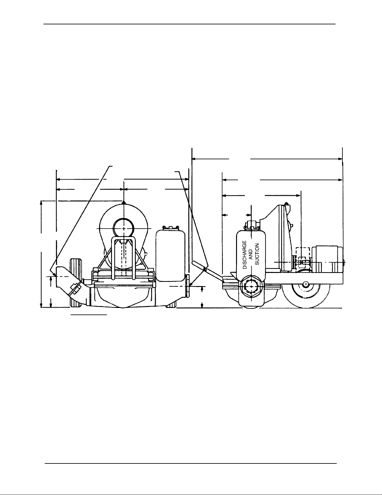
OUTLINE DRAWING
4” N.P.T. DISCHARGE
3” (OR 4”) N.P.T. SUCTION
33.88
[860,6]
17.00
[431,8]
APPROX
26.62
[676,1]
16.88
[428,8]
For further assistance, contact your Gorman‐Rupp
distributor or the Gorman‐Rupp Company.
Pump Dimensions
See Figure 1 for the approximate physical dimen
sions of this pump.
50.69
[1287,5]
[1370,1]
[185,7]
MOTOR FRAME 182T AND 184T
53.94
MOTOR FRAME 213 AND 215
32,31
MOTOR FRAME 182T AND 184T
[820,7]
34,94
MOTOR FRAME 213 AND 215
[887,5]
19.69
[500,1]
7.31
7.00
[177,8]
DIMENSIONS:
INCHES
[MILLIMETERS]
Figure 1. 4D Electric Motor Driven Pumps
PREINSTALLATION INSPECTION
The pump assembly was inspected and tested be
fore shipment from the factory. Before installation,
inspect the pump for damage which may have oc
curred during shipment. Check as follows:
a. Inspect the pump for cracks, dents, damaged
threads, and other obvious damage.
b. Check for and tighten loose attaching hard
ware. Since gaskets tend to shrink after dry
ing, check for loose hardware at mating sur
faces.
5,31
[134,9]
c. Carefully read all tags, decals, and markings
on the pump assembly, and perform all duties
indicated.
d. Check levels and lubricate as necessary. Re
fer to LUBRICATION in the MAINTENANCE
AND REPAIR section of this manual and per
form duties as instructed.
e. If the pump and motor have been stored for
more than 12 months, some of the compo
nents or lubricants may have exceeded their
maximum shelf life. These must be inspected
PAGE B - 1INSTALLATION
Page 8
OM-01510 D SERIES
or replaced to ensure maximum pump serv
ice.
If the maximum shelf life has been exceeded, or if
anything appears to be abnormal, contact your
Gorman‐Rupp distributor or the factory to deter
mine the repair or updating policy. Do not put the
pump into service until appropriate action has
been taken.
POSITIONING PUMP
Lifting
This pump is designed to be easily positioned for
operation using the drawbar and wheels. The total
pump weight is approximately 370 pounds (167,8
kg), not including accessories. Customer installed
equipment such as suction and discharge piping
must be removed before attempting to lift.
After the pump has been positioned, block the
wheels and secure the pump to prevent creeping.
SUCTION AND DISCHARGE PIPING
Pump performance is adversely effected by in
creased suction lift, discharge elevation, and fric
tion losses. See Page E‐1 to be sure your overall
application allows the pump to operate within the
safe operation range.
Materials
Either pipe or hose maybe used for suction and
discharge lines; however, the materials must be
compatible with the liquid being pumped. If hose is
used in suction lines, it must be the rigid‐wall, rein
forced type to prevent collapse under suction. Us
ing piping couplings in suction lines is not recom
mended.
Line Configuration
Death or serious personal injury and
damage to the pump or components
can occur if proper lifting procedures
are not observed. Make certain that
hoists, chains, slings or cables are in
good working condition and of suffi
cient capacity and that they are posi
tioned so that loads will be balanced
and the pump or components will not be
damaged when lifting. Suction and dis
charge hoses and piping must be re
moved from the pump before lifting. Lift
the pump or component only as high as
necessary and keep personnel away
from suspended objects.
Mounting
Locate the pump in an accessible place as close as
practical to the liquid being pumped. Level mount
ing is essential for proper operation.
The pump may have to be supported or shimmed
to provide for level operation or to eliminate vibra
tion.
Keep suction and discharge lines as straight as
possible to minimize friction losses. Make mini
mum use of elbows and fittings, which substan
tially increase friction loss. If elbows are necessary,
use the long‐radius type to minimize friction loss.
Never pull a line into place by tightening connec
tions at the pump. Lines near the pump must be in
dependently supported to avoid strain on the
pump which could cause excessive vibration and
increased diaphragm and gear train wear. If hose‐
type lines are used, they should have adequate
support to secure them when filled with liquid and
under pressure.
Fixed, Rigid Piping
This pump is equipped with an integral suction ac
cumulator chamber which promotes an efficient
flow of liquid and acts as an air cushion against
shock. Since the air in this chamber will leak away
during pump operation, the air must be replen
ished periodically. To introduce air into the cham
ber, stop the pump and remove the suction accu
mulator plug and integral gasket; this will break
prime and allow the liquid in the chamber to drain
away through the suction line.
If the pump is mounted in a system with fixed, rigid
piping, it is recommended that a flexible connec
PAGE B - 2 INSTALLATION
Page 9
D SERIES OM-01510
tion be installed at or near the suction and dis
charge ports to absorb shock which would other
wise be transmitted through the drive train and
greatly accelerate pump wear.
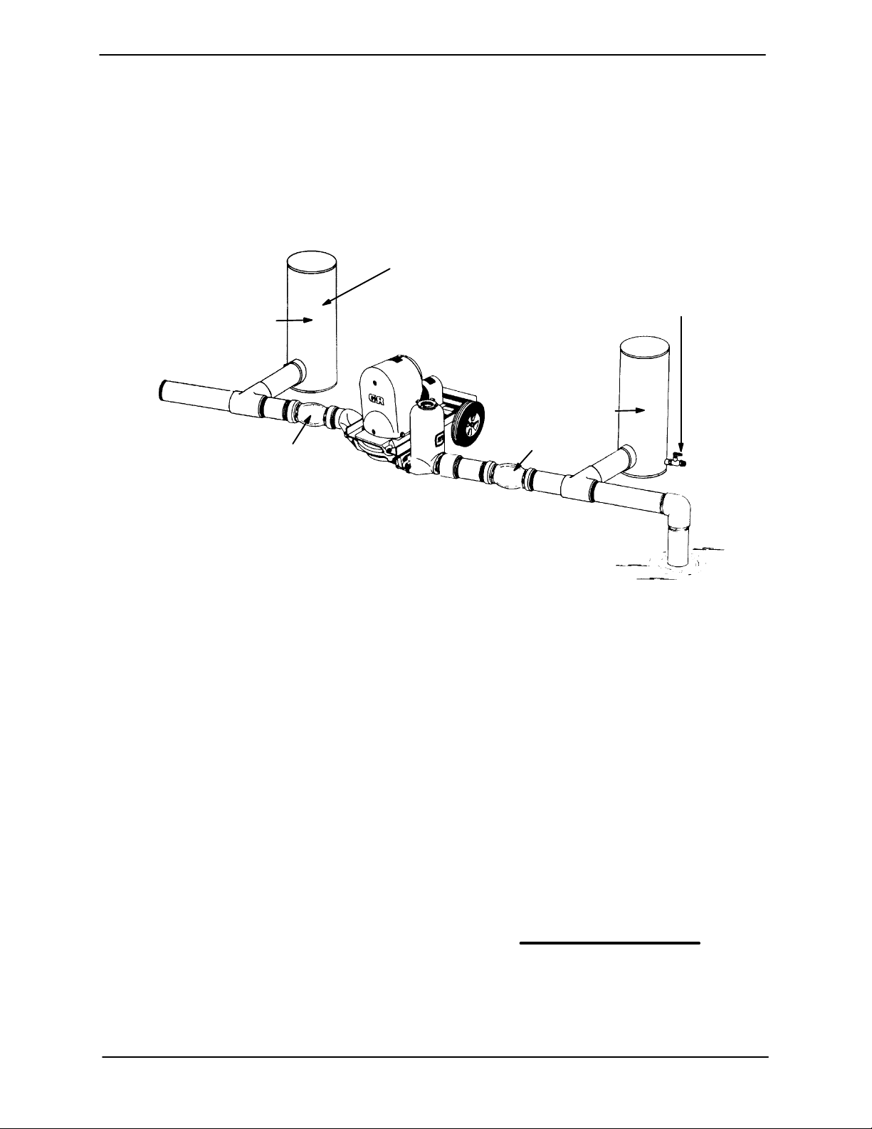
In a fixed piping installation, properly sized surge
AIR CHAMBERS
(18 TO 24 INCH LENGTHS OF
6 TO 8 INCH DIAMETER PIPE
WITH WELDED CAPS)
DISCHARGE
CHAMBER
DISCHARGE
FLEXIBLE JOINT
suppressors must be installed in both suction and
discharge lines. If commercial surge suppressors
are not readily available, air chambers may be fab
ricated from pipe as shown in Figure 2.
1/2‐INCH VALVE FOR
RECHARGING AIR
CHAMBER WITH
COMPRESSED AIR
(ALSO ON DISCHARGE
CHAMBER)
SUCTION
CHAMBER
FLEXIBLE JOINT
NOTE: INSTALL AIR CHAMBERS OFF FLOW LINE TEES
TO AVOID SURFACE TURBULENCE WITHIN CHAMBERS.
Figure 2. Fixed Piping Installation
Note that the air chambers have not been installed
directly in the flow line, but have been installed off
tees to avoid turbulence within the chambers. The
air chambers are fitted with valves to permit intro
duction of small amounts of compressed air to fur
ther dampen shock; this compressed air will leak
away during operation, and should be replaced
from time to time. If the suction chamber floods,
open the suction chamber valve to break prime
and allow the liquid in chamber to drain through
the suction line.
Gauges
SUCTION
SUCTION LINES
To avoid air pockets which could affect pump prim
ing, the suction line must be as short and direct as
possible. When operation involves a suction lift, the
line must always slope upward to the pump from
the source of the liquid being pumped; if the line
slopes down to the pump at any point along the
suction run, air pockets will be created.
NOTE
Maximum pump performance is realized at suction
lifts of 5 feet (1,5 m) or less. Use the shortest possi
ble length of suction hose or piping; lengths of 25
feet (7,6 m) or longer will reduce the capacity of the
pump.
If discharge pressure and vacuum suction gauges
are desired, drill and tap the suction and discharge
lines not less than 18 inches (457,2 mm) from the
suction and discharge ports and install the lines.
Installation closer to the pump may result in erratic
readings.
It is strongly recommended that no positive shut‐
off valve be installed in the suction line; excessive
restrictions will cause incomplete filling of the dia
phragm chamber and result in short diaphragm
life.
PAGE B - 3INSTALLATION
Page 10
OM-01510 D SERIES
Fittings
Suction lines should be the same size as the pump
inlet. If reducers are used in suction lines, they
should be the eccentric type, and should be in
stalled with the flat part of the reducers uppermost
to avoid creating air pockets. The suction line
should not be restricted more than 1 inch below the
nominal suction size.
The use of pipe couplings in the suction line is not
recommended.
Strainers
If a strainer is furnished with the pump, be certain
to use it; any spherical solids which pass through a
strainer furnished with the pump will also pass
through the pump itself.
If a strainer is not furnished with the pump, but is
installed by the pump user, make certain that the
total area of the openings in the strainer is at least
three or four times the cross section of the suction
line, and that the openings will not permit passage
of solids larger than the solids handling capability
of the pump.
line smaller than the suction; a restricted
discharge line will cause excessive friction
loss resulting in overloading and destruc
tion of pump and drive components.
Valves
The pump is provided with integral suction and dis
charge check valves.
Never install a positive shut‐off valve in the
discharge line; discharge restrictions will
cause excessive friction loss resulting in
overloading and destruction of pump and
drive components. It is strongly recom
mended that unless absolutely necessary,
no positive shut‐off valve be installed in the
suction line; excessive restriction will
cause incomplete filling of the diaphragm
chamber and result in shortened dia
phragm life.
ALIGNMENT
This pump is designed to handle up to 2‐1/4 inch
(57 mm) diameter spherical solids.
Sealing
Since even a slight leak will affect priming, head,
and capacity, especially when operating with a
high suction lift, all connections in the suction line
should be sealed with pipe dope to ensure an air
tight seal. Follow the sealant manufacturer's rec
ommendations when selecting and applying the
pipe dope. The pipe dope should be compatible
with the liquid being pumped.
DISCHARGE LINES
The discharge line must be the same size
as, or larger than, the suction line. Never in
stall or operate the pump with a discharge
Before attempting to open or service the
pump:
1. Familiarize yourself with this man
ual.
2. Shut off incoming power to the mo
tor and lock it out to ensure that the
pump will remain inoperative.
3. Allow the pump to completely cool
if overheated.
4. Close the discharge valve (if
used).
5. Drain the pump.
It is imperative that alignment be checked
before the pump is operated.
PAGE B - 4 INSTALLATION
Page 11
D SERIES OM-01510
The pump and motor were aligned and secured at
the factory, but fastening hardware may have loos
ened during shipment. It is imperative that this
hardware and the alignment be checked after the
pump is installed and before operation. Adjust
ments may be made by loosening the securing
hardware and shifting or shimming components
as required.
To check coupling alignment, use a feeler gauge or
taper gauge between the coupling halves every
90_. The coupling is in alignment when the hubs
are the same distance apart at all points.
To check parallel adjustment, lay a straightedge
across both coupling halves at the top, bottom and
sides. The horizontal parallel adjustment is correct
when the straightedge rests evenly on both halves
of the coupling at all points. Use a feeler gauge be
tween the coupling to measure any misalignment.
ELECTRICAL CONNECTIONS
Before connecting the motor to the incoming pow
er, check that the electrical service available
matches the pump motor requirements stamped
on the motor nameplate.
The pump must be operated in the direc
tion indicated by the arrow on the gearbox
and on the accompanying decals. Reverse
rotation could cause pump components to
be destroyed.
Never install a non‐explosion proof motor in an ex
plosive atmosphere. Be sure the motor is compat
ible with the intended application.
Do not operate the pump without the ec
centric and coupling guards in place
over the rotating parts. Exposed rotat
ing parts can catch clothing, fingers, or
tools, causing severe injury to person
nel.
Do not install and operate a non‐explo
sion proof motor in an explosive atmo
sphere. Install, connect, and operate
the motor in accordance with the Na
tional Electric Code and all local codes.
If there is a conflict between the instruc
tions in the manual accompanying the
unit and the National Electric Code or
the applicable local code, the National
or local code shall take precedence.
PAGE B - 5INSTALLATION
Page 12

D SERIES
OM-01510
OPERATION - SECTION C
Review all SAFETY information in Section A.
Follow the instructions on all tags, labels and
decals attached to the pump.
This pump is designed to handle non‐
volatile non‐flammable liquids contain
ing specified entrained solids. Do not
attempt to pump volatile, corrosive, or
flammable liquids which may damage
the pump or endanger personnel as a
result of pump failure.
After the pump has been installed, block
the wheels and secure the pump to pre
vent creeping. Make certain that the
pump and all piping or hose connec
tions are tight, properly supported and
secure before operation.
Pump application will affect its performance, espe
cially discharge velocities. Consult the Gorman‐
Rupp factory for actual performance levels for the
pump.
ened diaphragm life. No positive shut‐off
valve should be installed in the discharge
line.
STARTING
Consult the operations manual furnished with the
motor before starting the pump. Open any valves
installed in the suction line and start the pump.
OPERATION
The pump is designed to operate at ap
proximately 52 cycles per minute through
a gearbox with A 33.34:1 ratio and a 1750
RPM maximum input drive. Make certain
that the electric motor installed does not
exceed this rpm; otherwise, pump compo
nents may be destroyed.
Priming
The pump may not prime immediately because the
suction line must first fill with liquid. If the pump fails
to prime within five minutes, stop the motor and
check the suction line for leaks.
OPERATION CHECKS
Install the pump and piping as described in IN
STALLATION. Make sure that the piping connec
tions are tight, and that the pump is securely
mounted. Check that components are properly lu
bricated (see LUBRICATION in MAINTENANCE
AND REPAIR).
Make certain that any positive shut‐off
valve installed in the suction line is open
before operating the pump; excessive re
striction will cause incomplete filling of the
diaphragm chamber and result in short
OPERATION PAGE C - 1
Gearbox Check
Check that the gearbox is properly lubricated (see
LUBRICATION in MAINTENANCE AND RE
PAIR).
Leakage Check
No leakage should be visible at pump mating sur
faces, connections or fittings. Keep all line connec
tions and fittings tight to maintain maximum pump
efficiency.
Strainer Check
If a suction strainer has been installed, check and
clean it as necessary. It should be cleaned if pump
Page 13
OM-01510 D SERIES
flow begins to drop. If a vacuum suction gauge has
been installed, monitor and record the readings
regularly to detect strainer blockage.
Accumulator Chamber Check
Check periodically to ensure that there is sufficient
air in the integral suction accumulator chamber.
Replenish as required (see Fixed, Rigid Piping in
Section B for details).
STOPPING
After stopping the pump, shut off incoming power
to the motor and lock it out to ensure that the pump
will remain inoperative.
If the pump will be idle for more than a few hours, or
if it has been pumping liquids containing a large
amount of solids, flush it with clean water.
Cold Weather Preservation
The primary construction materials of this
pump are aluminum, with neoprene flap
valves and diaphragm. Do not attempt to
clean or flush this pump with any liquid
which would attack pump fittings or com
ponents. avoid cleaning with cleaning sol
vent.
In below freezing conditions, drain the water from
the pump and the lines when the pump is not in op
eration. Also, clean out any solids by flushing with a
hose.
GEARBOX TEMPERATURE CHECK
The gearbox runs higher than ambient tempera
tures because of heat generated by friction. Tem
peratures of approximately 200_ F (93_C) are con
sidered normal, and can operate intermittently at
250_F (121_C).
Checking gearbox temperatures by hand is inac
curate. Place a contact‐type thermometer against
the housing and record this temperature for future
reference.
A sudden increase in gearbox temperature is a
warning that the bearings are at the point of failing.
Make certain that the bearing lubricant is of the
proper viscosity and at the correct level (see LU
BRICATION in Section E). Bearing overheating
can also be caused by shaft misalignment and/or
excessive vibration.
When pumps are first started, the bearings may
seem to run at temperatures above normal. Con
tinued operation should bring the temperatures
down to normal levels within 20 minutes or less.
OPERATIONPAGE C - 2
Page 14
D SERIES OM-01510
TROUBLESHOOTING - SECTION D
Review all SAFETY information in Section A.
Before attempting to open or service the
pump:
1. Familiarize yourself with this manual.
2. Shut off incoming power to the motor
and lock it out to ensure that the
pump will remain inoperative.
3. Allow the pump to completely cool if
overheated.
4. Close the discharge valve (if used).
5. Drain the pump.
TROUBLE POSSIBLE CAUSE PROBABLE REMEDY
PUMP FAILS TO
PRIME
PUMP STOPS OR
FAILS TO DELIVER
RATED FLOW OR
PRESSURE
Air leak in suction line. Correct leak.
Lining of suction hose collapsed. Replace suction hose.
Integral suction or discharge check Clean valves, check that flange nuts
valve clogged, binding, or not seating are tight.
properly.
Cracked or broken diaphragm. Replace diaphragm.
Diaphragm not securely in place. Secure diaphragm.
Strainer clogged. Check strainer and clean if necessary.
Air leak in suction line. Correct leak.
Suction intake not properly submerged. Check installation.
Lining of suction hose collapsed. Replace suction hose.
Cracked or broken diaphragm. Replace diaphragm.
Diaphragm not securely in place. Secure diaphragm.
Strainer clogged. Check strainer and clean if necessary.
Integral suction or discharge check Clean valves, check that flange nuts
valve clogged, binding, or not seating are tight.
properly.
TROUBLESHOOTING PAGE D - 1
Page 15
OM-01510 D SERIES
TROUBLE POSSIBLE CAUSE PROBABLE REMEDY
PUMP REQUIRES
TOO MUCH
POWER
PUMP CLOGS
FREQUENTLY
EXCESSIVE NOISE
BEARINGS RUN
TOO HOT
Liquid solution too thick. Dilute if possible.
Integral discharge check valve clogged Clean valve.
or binding.
Bearings in motor or gearbox Check bearings.
worn or binding.
Integral suction or discharge check Clean valves, check that flange nuts
valve clogged, binding, or not seating are tight.
properly.
Liquid solution too thick. Dilute if possible.
Pump, gearbox, or motor not Check and tighten mounting bolts.
securely mounted.
Gearbox or motor not properly See LUBRICATION in MAINTE‐
lubricated. NANCE AND REPAIR.
Bearing temperature is high, but within Check bearing temperature regularly
limits. to monitor any increase.
Low or incorrect lubricant. Check for proper type and level of
lubricant.
Drive misaligned. Align drive properly.
TROUBLESHOOTINGPAGE D - 2
Page 16
D SERIES OM-01510
PUMP MAINTENANCE AND REPAIR ‐ SECTION E
MAINTENANCE AND REPAIR OF THE WEARING PARTS OF THE PUMP WILL MAINTAIN PEAK
OPERATING PERFORMANCE.
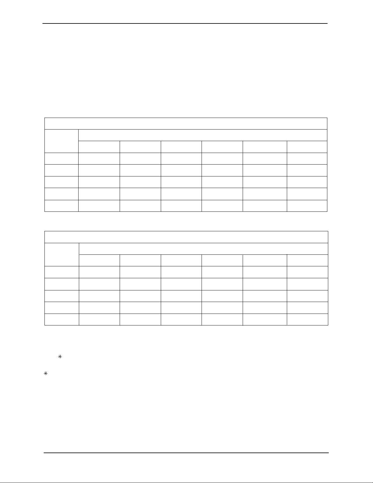
IN GALLONS PER MINUTE AT 52 STROKES PER MINUTE
STATIC
LIFT
IN FEET
5 150 119 113 112
10 126 108 105 105
20 94 74 73 66
STATIC
LIFT
IN METERS
1,5 567,8 450,4 427,7 423,9
3,0 476,9 408,8 397,4 397,4
4,6 370,9 283,8 280,1 276,3
6,1 355,8 280,1 276,3 249,8
0101520
IN LITERS PER MINUTE AT 52 STROKES PER MINUTE
0 3,0 4,6 6,1
STATIC DISCHARGE HEAD IN FEET
5
125
118
97
82
82
STATIC DISCHARGE HEAD IN METERS
1,5
473,1
446,6
367,1
310,3
25
104
100
7374759815
6066707425
70
63
52
7,6
393,6
378,5
264,9
238,4
7,6 280,1 264,9 249,8 227,1
STANDARD PERFORMANCE TEST DATA FOR 4D ELECTRIC MOTOR DRIVEN PUMPS
Based on 70_ F (21_ C) clear water at sea level
with minimum suction lift, using 3 inch (7,62 cm)
suction hose and 4 inch (10,16 cm) non‐collapsible
discharge hose. Since pump installations are sel
dom identical, your performance may be different
due to such factors as viscosity, specific gravity,
elevation, temperature, and impeller trim.
MAINTENANCE & REPAIR PAGE E - 1
310,3
If your pump serial number is followed by an “N”,
your pump is NOT a standard production model.
Contact the Gorman‐Rupp Company to verify per
formance or part numbers.
196,8
Page 17
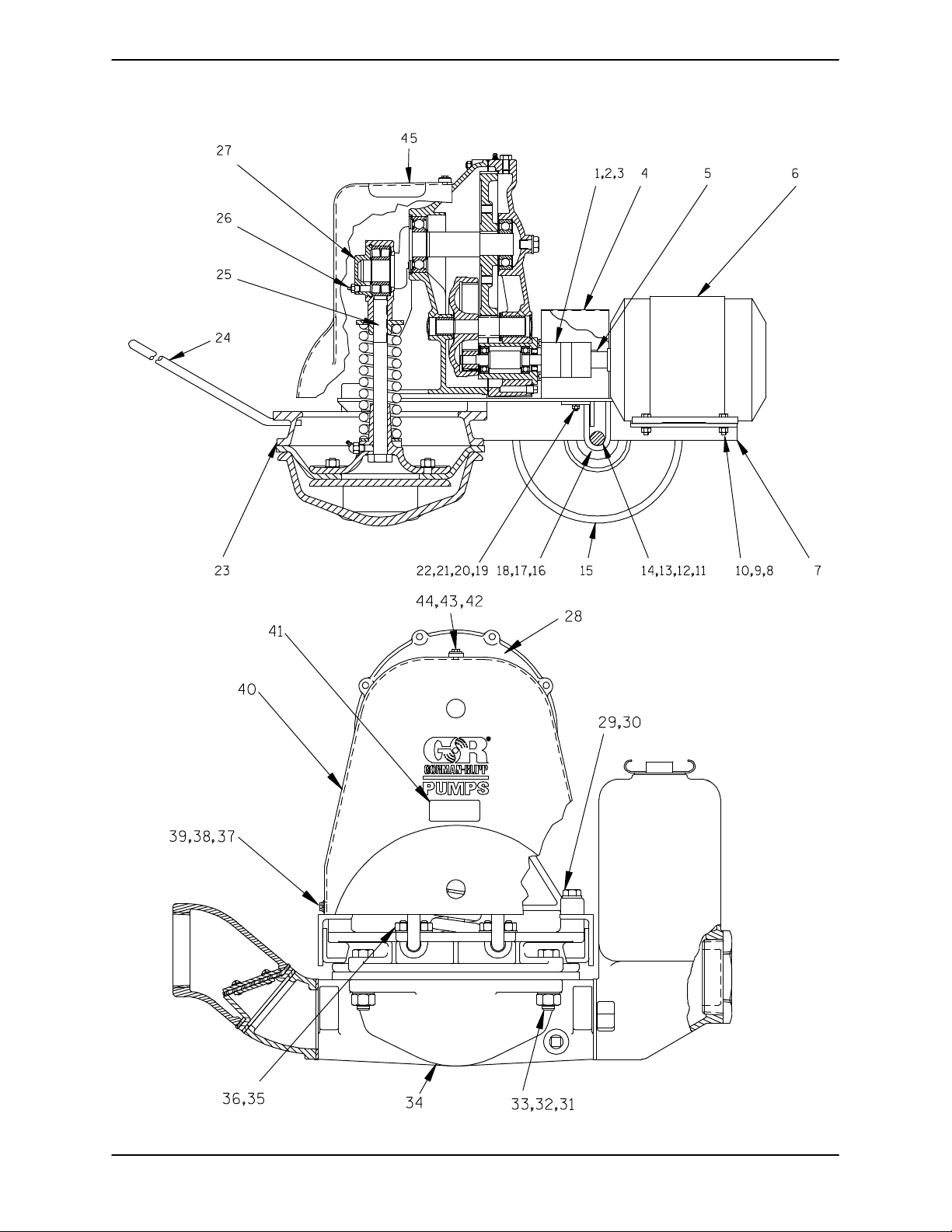
SECTION DRAWING
D SERIESOM-01510
Figure 1. 4D-E3 3P
MAINTENANCE & REPAIRPAGE E - 2
Page 18
D SERIES OM-01510
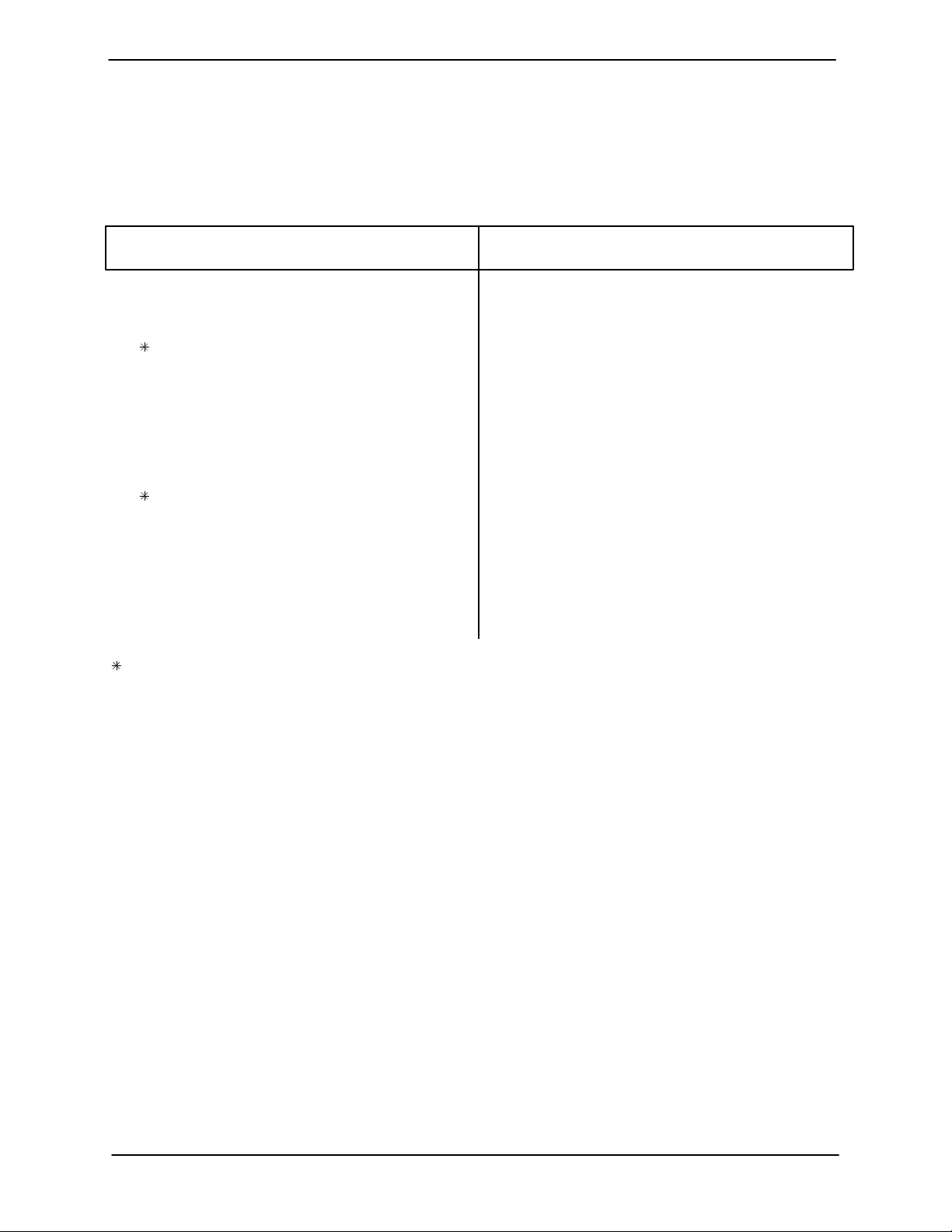
PARTS LIST
Pump Model 4D-E3 3P
(From S/N 504867 up)
If your pump serial number is followed by an “N”, your pump is NOT a standard production model. Contact
the Gorman‐Rupp Company to verify part numbers.
ITEM
PART NAME PART
NO.
NUMBER
QTY ITEM
NO.
PART NAME PART
NUMBER
QTY
1 DRIVE SHAFT CPLNG 24355-105 1
2 MOTOR SHAFT CPLNG 24355-112 1
3 SPIDER 24355-267 1
4 COUPLING GUARD 34613-045 15020 1
5 KEY N0408 15990 1
6 MOTOR 28216-442 1
7 BASE 13485 24000 1
8 HEX HD CAPSCREW B0605 15991 4
9 HEX NUT D06 15991 4
10 LOCKWASHER J06 15991 4
11 AXLE 6619 15990 1
12 SPACER 6619A 15070 2
13 COTTER PIN M0306 15990 2
14 FLAT WASHER S1532 4
15 PNEUMATIC WHEEL S0263 2
16 U‐BOLT 6945 15000 2
17 HEX NUT D06 15991 4
18 LOCKWASHER J06 15991 4
19 HEX HD CAPSCREW B0404 15991 2
20 FLAT WASHER K04 15991 2
21 LOCKWASHER J04 15991 2
22 HEX NUT D04 15991 2
23 DIAPHRAGM RING 6621 13010 1
24 DRAW BAR 5438 15990 1
INDICATES PARTS RECOMMENDED FOR STOCK
25 PLUNGER ROD ASSY 6959 1
26 LUB FITTING S191 1
27 END CAP 6643 10010 1
28 GEARBOX ASSY 44161-009 1
29 HEX HD CAPSCREW B01010 15991 4
30 LOCKWASHER J10 15991 4
31 HEX NUT D12 15991 4
32 LOCKWASHER J12 15991 4
33 HEX HD CAPSCREW B1212 15991 4
34 DIAPHRAGM POT ASSY 46475-702 1
35 U‐BOLT 5495 15991 2
36 HEX NUT W/FLANGE 21765-314 4
37 HEX HD CAPSCREW B0402-1/2 15991 2
38 T TYPE LOCKWASHER AK04 15991 2
39 FLAT WASHER K04 15991 2
40 ECCENTRIC GUARD 38861-504 23200 1
41 LUBE DECAL 38817-066 1
42 NYLOCK CAPSCREW BT0403 15991 1
43 WASHER S157 1
44 FLAT WASHER K04 15991 1
45 GRD WARNING STCKR 38816-063 1
NOT SHOWN:
NAME PLATE 2613BP 13990 1
DRIVE SCREW BM#04-03 17000 4
STRAINER 4917 24001 1
MAINTENANCE & REPAIR PAGE E - 3
Page 19
13
D SERIESOM-01510
ILLUSTRATION
5
12
7
6
14
9
10
11
13
12
14
3
15
8
13
12
2
10
14
9
11
6
7
4
1
16
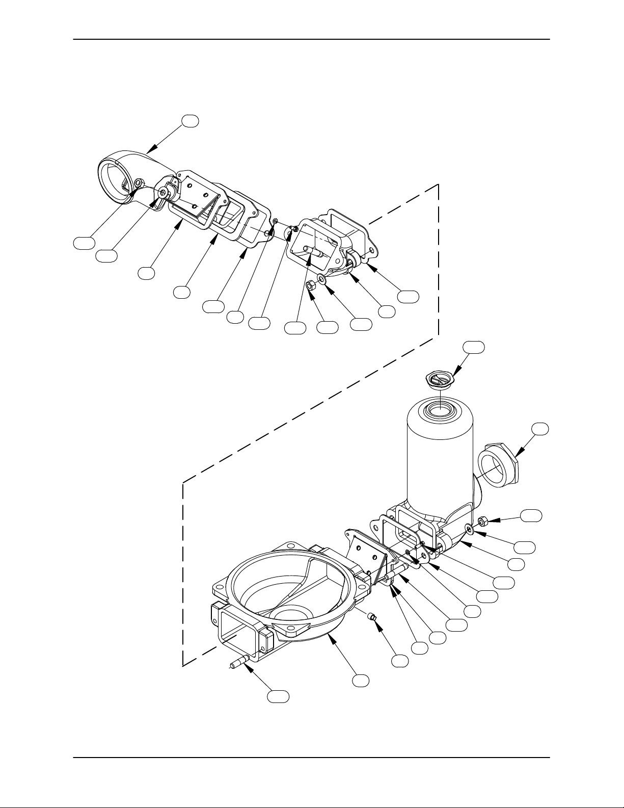
Figure 2. Diaphragm Pot Assembly
MAINTENANCE & REPAIRPAGE E - 4
Page 20
D SERIES OM-01510
PARTS LIST
Diaphragm Pot Assembly
ITEM
NO.
1 POT-DIAPHRAM 6622 13010 1
2 ACCUMULATOR & SUCTION FLANGE 6625 13010 1
3 DISCHARGE FLANGE 6627 13040 1
4 PIPE PLUG P06 15079 1
5 DISCHARGE ELBOW 6626 13040 1
6 VALVE SEAT 6635 10010 2
7 FLAP VALVE ASSY 46413-007 2
8 REDUCER PIPE BUSHING AP6448 11990 1
9 LOCK WASHER J05 15991 4
10 HEX HEAD CAP SCREW B0504 15991 4
11 STUD C1013 15991 4
12 WASHER SAE 5/8 21161-442 6
13 HEX NUT D10 15991 6
14 GASKET 6625G 19100 3
15 DRUM PLUG W/ GASKET 25142-010 1
16 STUD C1010 15991 2
INDICATES PARTS RECOMMENDED FOR STOCK
PART NAME
PART
NUMBER
QTY
MAINTENANCE & REPAIR PAGE E - 5
Page 21
13
D SERIESOM-01510
SECTION DRAWING
234
,,
1
5
10
12
8.00 REF
10.78 HOLD
11
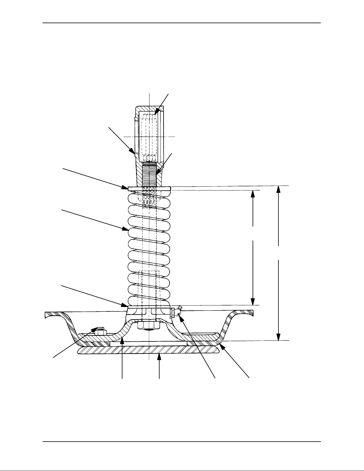
Figure 3. 6959 Plunger Rod Assembly
6789
MAINTENANCE & REPAIRPAGE E - 6
Page 22
D SERIES OM-01510
PARTS LIST
6959 Plunger Rod Assembly
ITEM
NO.
1 BEARING CAP 6560 10010 1
2 -HEX HD CAPSCREW B0813S 15991 2
3 -HEX NUT D08S 15991 2
4 -LOCKWASHER J08 15991 2
5 PLUNGER ROD ASSEMBLY 6633 15990 1
6 DIAPHRAGM S1017 1
7 LUBRICATION FITTING S194 1
8 DIAPHRAGM PLATE 6629 15990 1
9 DIAPHRAGM PLATE 6628 10010 1
10 HEX NUT D08 15991 4
11 SPRING WASHER 6639 15000 1
12 SPRING 6547 16080 1
13 SPRING RETAINING NUT 6638 11000 1
INDICATES PARTS RECOMMENDED FOR STOCK
PART NAME
PART
NUMBER
QTY
MAINTENANCE & REPAIR PAGE E - 7
Page 23
SECTION DRAWING
D SERIESOM-01510
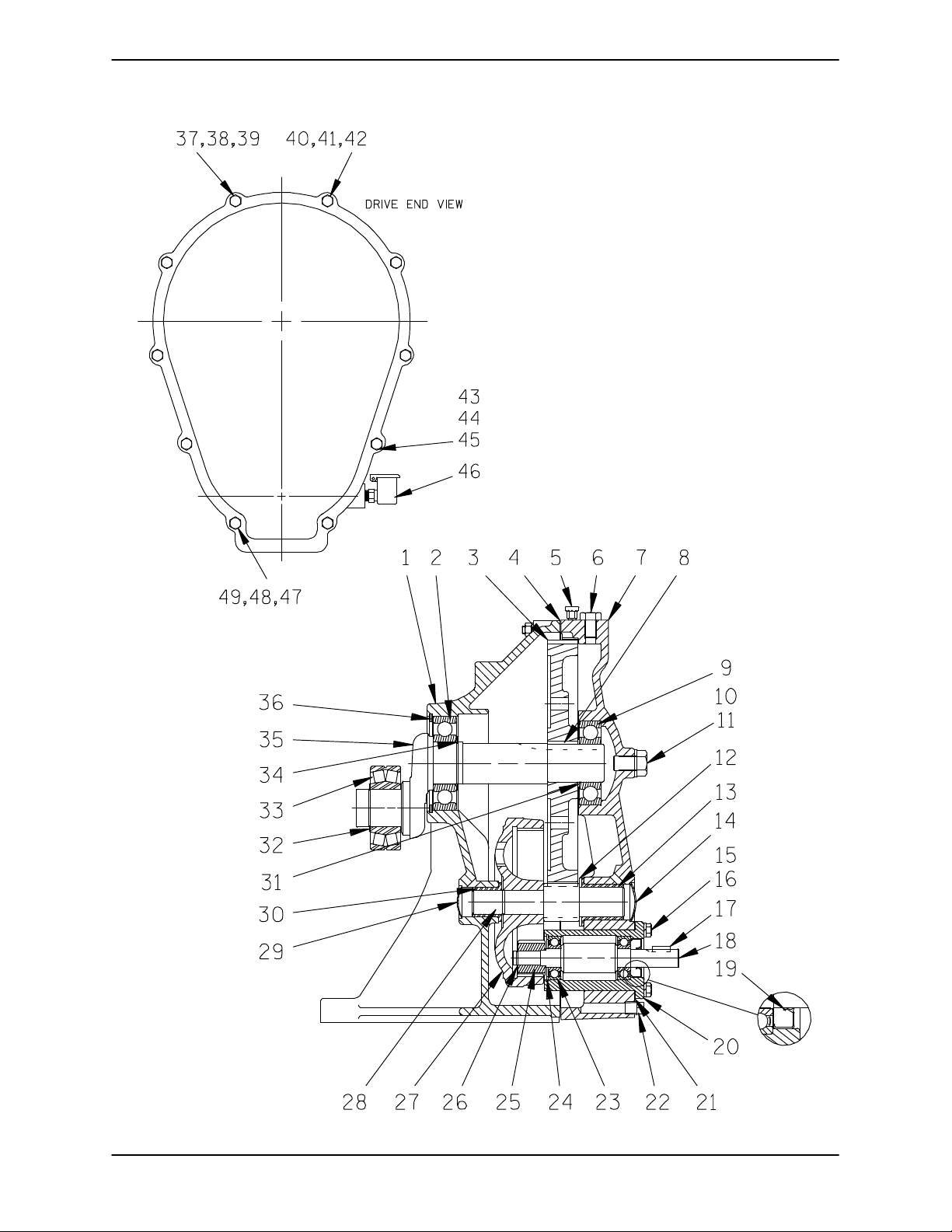
Figure 4. Gearbox Assembly
MAINTENANCE & REPAIRPAGE E - 8
Page 24

D SERIES OM-01510
PARTS LIST
Gearbox Assembly
ITEM
PART NAME PART
NO.
NUMBER
QTY ITEM
NO.
PART NAME PART
NUMBER
QTY
1 GEAR HOUSING 6624 13040 1
2 CRANKSHAFT BEARING S374 1
CRANKSHAFT GEAR 6641 15060 1
3
4 GEAR HOUSING GSKT 6624G 18000 1
5 AIR VENT FITTING S2162 1
6 HEX HD CAPSCREW B0803 15991 1
7 GEAR COVER 6623 13010 1
8 CRANKSHAFT GEAR KEY N0605 15990 1
9 CRANKSHAFT BEARING S1080 1
10 HEX HD CAPSCREW B1004 15991 1
11 FLAT WASHER 21161-442 1
12 WASHER 6637 15000 1
13 PINION BUSHING S1016 1
14 GEAR COVER PLUG S1053 1
15 HEX HD CAPSCREW B0504 15991 4
16 LOCKWASHER J05 15991 4
17 DRIVE SHAFT KEY N0304 15990 1
18 DRIVE SHAFT 6631 15010 1
19 OIL SEAL S1012 1
20 ECCENTRIC HOUSING 6632 10010 1
21 ECC HOUSING GSKT 6632G 18000 1
22 DRAIN PLUG P04 15079 1
23 DRIVE SHAFT BEARING S1044 2
24 RETAINING RING S204 1
INDICATES PARTS RECOMMENDED FOR STOCK
25 DRIVE GEAR 6558 16040 1
26 SNAP RING S1004 1
27 PINION GEAR S1014 1
28 PINION SHAFT 6634 16070 1
29 GEAR HOUSING PLUG S1054 1
30 PINION SHAFT BUSHING S1015 1
31 SPACER 6636 15990 1
32 SNAP RING S244 1
33 ROLLER BEARING S1011 1
34 RETAINING RING S442 1
35 CRANKSHAFT 6550 11000 1
36 SNAP RING S1010 1
37 HEX HD CAPSCREW B0511 15991 5
38 LOCKWASHER J05 15991 5
39 HEX NUT D05 15991 5
40 SHOULDER BOLT S1018 1
41 LOCKWASHER J05 15991 1
42 HEX NUT D05 15991 1
43 HEX HD CAPSCREW B0518 15991 3
44 LOCKWASHER J05 15991 3
45 HEX NUT D05 15991 3
46 OIL CUP S617 1
47 SHOULDER BOLT S1019 1
48 LOCKWASHER J05 15991 1
49 HEX NUT D05 15991 1
MAINTENANCE & REPAIR PAGE E - 9
Page 25
OM-01510
PUMP AND SEAL DISASSEMBLY
AND REASSEMBLY
D SERIES
Review all SAFETY information in Section A.
Follow the instructions on all tags, label and de
cals attached to the pump.
This pump requires little service due to its rugged,
minimum‐maintenance design. However, if it be
comes necessary to inspect or replace the wearing
parts, follow these instructions which are keyed to
the sectional views (see Figures 1 thru 4) and the
accompanying parts lists.
This manual will alert personnel to
known procedures which require spe
cial attention, to those which could
damage equipment, and to those which
could be dangerous to personnel. How
ever, this manual cannot possibly antici
pate and provide detailed instructions
and precautions for every situation that
might occur during maintenance of the
unit. Therefore, it is the responsibility of
the owner/maintenance personnel to
ensure that only safe, established main
tenance procedures are used, and that
any procedures not addressed in this
manual are performed only after estab
lishing that neither personal safety nor
pump integrity are compromised by
such practices.
Most service functions may be performed without
separating the pump and gearbox from the motor.
If major repair is required, the pump, gearbox and
motor must be disconnected.
Before attempting to open or service the
pump:
1. Familiarize yourself with this man
ual.
2. Shut off incoming power to the mo
tor and lock it out to ensure that the
pump will remain inoperative.
3. Allow the pump to completely cool
if overheated.
4. Close the discharge valve (if
used).
5. Drain the pump.
Use Only Genuine Gorman-Rupp re
placement parts. Failure to do so may cre
ate a hazard and damage the pump or di
minish optimal pump performance. Any
such hazard, damage or diminished per
formance is not covered by the warranty.
NOTE
When appropriate recycling facilities are available,
the user should recycle components and fluids
when doing any routine maintenance / repairs and
also at the end of the pump’s useful life. All other
components and fluids shall be disposed of ac
cording to all applicable codes and regulations.
Before attempting to service the pump, drain the
pump by removing the drain plug (11, Figure 2).
Clean and reinstall the drain plug.
Suction And Discharge Check Valve Removal
Before attempting to service the pump, shut off in
coming power to the motor and lock it out to ensure
that it will remain inoperative. Close all valves in the
suction and discharge lines.
For motor disassembly and repair, consult the lit
erature supplied with the motor, or contact your lo
cal motor representative.
(Figure 2)
To service the suction and discharge check valves,
remove the suction and discharge piping.
To service the suction check valve assembly (7), re
move the suction accumulator (2) by loosening the
hardware (12 and 13) securing it to the diaphragm
pot (1). Remove the hardware (9 and 10) securing
MAINTENANCE & REPAIRPAGE E - 10
Page 26

OM-01510D SERIES
the valve seat (6) and check valve assembly to the
diaphragm pot. Pull the check valve assembly from
the suction port.
To service the discharge check valve assembly (7),
loosen the hardware (12 and 13) and remove the
assembled outboard discharge elbow (5), check
valve, and seat (6). Remove the gasket (14).
Remove the hardware (9 and 10) securing the
valve seat (6) and discharge check valve assembly
to the discharge elbow.
To remove the inboard discharge flange (3), loosen
the hardware (12 and 13) securing the flange to the
diaphragm pot. Remove the gasket (14).
If no further disassembly is required, see Suction
And Discharge Check Valve Installation.
Diaphragm Removal
(Figure 1)
Use a socket wrench to hold the plunger rod (5) se
curely, and unscrew the bearing cap assembly (1).
Unscrew the spring retaining nut (13). Use caution
when unscrewing the retaining nut; tension on the
spring (12) will be released.
Remove the spring (12) and spring washer (11).
Slide the plunger rod assembly (5) out of the upper
diaphragm plate (9).
Inspect the component parts for excessive wear
and replace as required.
Gearbox Removal And Disassembly
(Figure 1)
When properly operated and maintained, the gear
box assembly (28) should not require disassembly.
Disassemble the gearbox only when there is evi
dence of wear or damage.
To remove the diaphragm (6, Figure 3), disengage
the hardware (31, 32 and 33) and remove the dia
phragm pot assembly (34). Inspect the diaphragm
ring (23) for wear or damage. If replacement is re
quired, the gearbox assembly (28) must be re
moved.
(Figure 3)
Remove the nuts (10). Separate the lower dia
phragm plate assembly (8) from the diaphragm (6)
and the upper diaphragm plate (9). Inspect the dia
phragm and replace a required.
If no further disassembly is required, see Dia
phragm Installation.
Plunger Rod Removal And Disassembly
(Figure 3)
With the diaphragm pot assembly and diaphragm
removed, disengage the hardware (38, 39, 40, 43,
44, and 45, Figure 1) and remove the eccentric
guard (41, Figure 1).
Loosen the hardware (2, 3 and 4) and remove the
end cap (27, Figure 1). Slide the bearing cap (1) off
the crankshaft roller bearing (33, Figure 4), and re
move the plunger rod assembly.
Shaft and bearing disassembly in the field
is not recommended. These operations
should be performed only in a properly
equipped shop by qualified personnel.
Support the diaphragm ring (23) with wooden
blocks. Disengage the hardware (29 and 30) and
remove the diaphragm ring. Inspect the dia
phragm ring for wear or damage and replace as
necessary. It is not necessary to remove the draw
bar (24) from the diaphragm ring unless replace
ment is required. Disengage the hardware (36 and
37) from the U‐bolts (35) to remove the drawbar.
Disengage the hardware (19, 20, 21 and 22) and
remove the coupling guard (4). Loosen the hard
ware securing the drive shaft coupling (1). Sepa
rate the gearbox assembly from the coupling by
pulling straight away. Remove the shaft key (17,
Figure 4).
(Figure 4)
Before attempting to disassemble the gearbox as
sembly, drain the lubricant by removing the drain
plug (22) and turning the gearbox on its side. Clean
and reinstall the drain plug.
Remove the hardware (15 and 16) securing the ec
centric housing (20) and housing gasket (21) to the
MAINTENANCE & REPAIR PAGE E - 11
Page 27
OM-01510
D SERIES
gear cover (7). Pull the complete drive shaft sub‐
assembly from the gear cover.
To disassemble the drive shaft subassembly, re
move the snap ring (26) and slide the drive gear
(25) off the drive shaft (18). Remove the retaining
ring (24), and press the drive shaft and assembled
bearings (23) out of the eccentric housing. Press
the oil seal (19) from the housing bore. Cover the
shaft and bearing with a clean cloth until ready to
clean and inspect the gearbox components.
For access to the remaining gearbox drive compo
nents, the gear cover (7) and gear housing gasket
(4) must be separated from the gear housing (1) by
removing the two close‐tolerance shoulder bolts
(40 and 47), which act as pilots to ensure accurate
concentric positioning of the cover, and the re
maining hardware (37, 38, 39, 41, 42, 43, 44, 45, 48
and 49).
NOTE
The shoulder bolts and capscrews securing the
gearbox cover to the gearbox housing are of differ
ent lengths. For ease of reassembly, record the po
sitions of the shoulder bolts and capscrews at the
time of removal.
Remove the gear housing gasket and clean all the
mating surfaces.
Install two 5/8‐11 UNC capscrews in the tapped
holes in the crankshaft gear (3), and use a gear
puller to slide the gear off the crankshaft. Retain the
crankshaft gear key (8). Remove the capscrews
from the gear.
Remove the snap ring (36) and slide the crankshaft
and crankshaft bearing (2) out of the gearbox
housing.
To disassemble the pinion shaft and components,
slide the shaft and assembled pinion gear (27) out
of the shaft bushing (30). The pinion gear is re
tained on the shaft by tight friction fit and does not
normally require removal. If removal is required,
press the pinion gear from the shaft.
Inspect the pinion shaft bushing and, if replace
ment is required, remove the plug (29) and press
the bushing from the gear housing bore.
After removing the shafts and bearings, clean and
inspect the bearings in place as follows.
To prevent damage during removal from
the shaft, it is recommended that bearings
be cleaned and inspected in place. It is
strongly recommended that the bearings
be replaced any time the shaft and bear
ings are removed.
NOTE
If the gear cover does not readily separate from the
housing, remove the hardware (10 and 11), install a
5/8‐11 UNC by 4‐inch long capscrew, and jack the
cover from the housing. Remove the jacking screw
and replace the hardware (10 and 11).
After the gear cover has been removed, inspect the
pinion shaft bushing (13). If replacement is re
quired, remove the cover plug (14) and press the
pinion shaft bushing (13) from the cover bore. Slide
the pinion shaft washer (12) off the pinion shaft (28)
and tag it for reference during reassembly.
Use a bearing puller to remove the crankshaft
bearing (9) from the crankshaft (35). Remove the
spacer (31).
Clean the gear housing, shaft and all component
parts (except the bearings) with a soft cloth soaked
in cleaning solvent. Inspect the parts for wear or
damage and replace as necessary.
Most cleaning solvents are toxic and
flammable. Use them only in a well ven
tilated area free from excessive heat,
sparks, and flame. Read and follow all
precautions printed on solvent contain
ers.
Clean the bearings thoroughly in fresh cleaning
solvent. Dry the bearings with filtered compressed
air and coat with light oil.
MAINTENANCE & REPAIRPAGE E - 12
Page 28
Bearings must be kept free of all dirt and
foreign material. Failure to do so will great
ly shorten bearing life. Do not spin dry
bearings. This may scratch the balls or
races and cause premature bearing fail
ure.
Rotate the bearings by hand to check for rough
ness or binding and inspect the bearing balls. If ro
tation is rough or the bearing balls are discolored,
replace the bearings.
The bearing tolerances provide a tight press fit
onto the shafts and a snug slip fit into the gear
housing. Replace the bearings, shafts, eccentric
housing, or gear housing if the proper bearing fit is
not achieved.
If the bearings require replacement, remove the
bearing retaining ring (34). Remove the bearing
snap ring (32) and use a bearing puller to remove
the bearings (2, 23 and 33).
Gearbox Reassembly And Installation
(Figure 4)
OM-01510D SERIES
NOTE
If a hot oil bath is used to heat the bearings, both the
oil and the container must be absolutely clean. If
the oil has been previously used, it must be thor
oughly filtered.
Heat the bearings to a uniform temperature no
higher than 250_F (120_C), and slide the bearings
onto the shafts, one at a time, until they are fully
seated. This should be done quickly, in one con
tinuous motion, to prevent the bearings from cool
ing and sticking on the shaft.
Use caution when handling hot bear
ings to prevent burns.
NOTE
The crankshaft bearing (9) must be installed after
the crankshaft gear (3).
After the bearings have been installed and allowed
to cool, check to ensure that they have not moved
out of position in shrinking. If movement has oc
curred, use a suitable sized sleeve and a press to
reposition the bearings.
Inspect the shafts (18, 28 and 35) for distortion,
nicks or scratches. Dress small nicks and burrs
with a fine file or emery cloth. Replace the shafts if
defective.
If heating the bearings is not practical, use a suit
able sized sleeve and an arbor (or hydraulic) press
to install the bearings on the shaft.
When installing the bearings onto the
To prevent damage during removal from
the shaft, it is recommended that bearings
be cleaned and inspected in place. It is
strongly recommended that the bearings
be replaced any time the shaft and and
bearings are removed.
The bearings may be heated to ease installation.
An induction heater, hot oil bath, electric oven, or
hot plate may be used to heat the bearings. Bear
ings should never be heated with a direct flame or
directly on a hot plate.
MAINTENANCE & REPAIR PAGE E - 13
shaft, never press or hit against the outer
race, balls, or ball cage. Press only on the
inner race.
Secure the bearing (2) with the snap ring (34). Se
cure the crankshaft roller bearing (33) with the
snap ring (32).
If removed, press the pinion shaft bushing (30) into
the gear housing until fully seated.
Use a hydraulic press to install the pinion gear (27)
onto the pinion shaft (28).
Page 29
OM-01510
D SERIES
NOTE
The pinion gear is a tight interference fit on the pin
ion shaft. To ease installation, the gear may be
heated (and the shaft cooled) to a temperature dif
ferential of 350_F (177_C). If the gear is heated, use
caution when handling the gear to prevent burns.
Slide the assembled pinion shaft and gear into the
pinion shaft bushing until fully seated.
Slide the crankshaft and assembled bearing (2)
into the gear housing and secure with the snap ring
(36).
When installing the shaft and bearings into
the bearing bore, push against the outer
race. Never hit the balls or ball cage.
Install the crankshaft gear key (8) in the shaft key
way. Align the crankshaft gear teeth with those on
the pinion shaft, and press the gear onto the crank
shaft until fully seated against the shoulder. Install
the spacer (31), and press the bearing (9) onto the
shaft until fully seated against the spacer.
Tap the end of the crankshaft with a soft‐faced mal
let to ensure that all components are fully seated.
Press the drive shaft and assembled bearings into
the eccentric housing (20), and secure with the re
taining ring (24).
When installing the shaft and bearings into
the bearing bore, push against the outer
race. Never hit the balls or ball cage.
Lubricate the lip of the oil seal (19) with light oil, and
position it on the drive shaft with the lip positioned
as shown in Figure 4. Press the oil seal into the ec
centric housing bore until the face of the oil seal is
just flush with the face of the eccentric housing.
Be careful not to roll or cut the lip of the oil seal on
the shaft keyway.
Install the drive gear (25) on the drive shaft, and se
cure with the snap ring (26).
Clean the mating surface of the eccentric housing
and replace the eccentric housing gasket (21). Po
sition the assembled eccentric housing and drive
shaft in the gear cover bore with the word “top” on
the eccentric housing flange facing up. Slide the
housing and drive shaft into the gearbox, making
certain the drive gear teeth fully engage those of
the pinion gear. Secure the eccentric housing to
the gear housing with the hardware (15 and 16).
Install the drive shaft key (17).
If removed, press the pinion shaft bushing (13) into
the gear cover (7). Slide the pinion shaft washer
(12) onto the pinion shaft (28). Install the gear
housing gasket (4). Position the gear cover so that
the respective bores slip over the crankshaft bear
ing and pinion shaft. Tap the cover into place with a
soft‐faced mallet.
Install the two close‐tolerance shoulder bolts (40
and 47) (which act as pilots to ensure accurate
concentric positioning of the cover) through their
respective holes, and secure them with the hard
ware (41, 42, 48 and 49). Secure the gear cover to
the gear housing by tightening the remaining hard
ware (37, 38, 39, 43, 44, 45 and 46) evenly.
Install the gear cover plug (14) and the gear hous
ing plug (29).
(Figure 1)
Position the gearbox on the base (7). Position the
diaphragm ring (23) under the base, and secure
the gearbox and diaphragm ring with the hardware
(29 and 30).
If the drawbar (24) was removed, secure it to the
diaphragm ring with the U‐bolts (35) and hardware
(36 and 37).
Secure the drive shaft coupling (1) to the drive
shaft. Check the coupling alignment as described
in ALIGNMENT, Section B. Install the coupling
guard (4) and secure it with the hardware (19, 20,
21 and 22).
Lubricate the gearbox as described in LUBRICA
TION.
MAINTENANCE & REPAIRPAGE E - 14
Page 30
OM-01510D SERIES
Plunger Rod Reassembly And Installation
(Figure 3)
Slide the plunger rod (5) through the upper dia
phragm plate (9). Slide the spring washer (11) and
spring (12) down over the plunger rod. Install the
spring retaining nut (13), and tighten it to obtain the
dimension shown in Figure 3.
Clean the bearing cap (1) with a cloth soaked in
cleaning solvent.
Most cleaning solvents are toxic and
flammable. Use them only in a well ven
tilated area free from excessive heat,
sparks, and flame. Read and follow all
precautions printed on solvent contain
ers.
Diaphragm Installation
(Figure 3)
Position the diaphragm (6) on the upper dia
phragm plate (9), making sure the lip is properly
seated. Slide the studs in the lower diaphragm
plate (8) through the holes in the upper diaphragm
plate, and secure with the nuts (10).
(Figure 1)
Secure the diaphragm pot assembly (34) to the di
aphragm ring (23) with the hardware (31, 32 and
33).
Suction And Discharge Check Valve Installation
(Figure 2)
Inspect the check valve components and replace
as required.
If the inboard discharge flange (3) was removed,
clean the mating surfaces and install the gasket
(14). Secure the flange to the diaphragm pot (1)
with the hardware (12 and 13).
Inspect the bearing cap for wear or damage and
replace if necessary.
NOTE
The bearing cap consists of an upper and lower half
secured with the hardware (2, 3 and 4). The cap is
machined as one piece before being split to ensure
concentricity of the bore, and is available only as an
assembly.
Screw the bearing cap assembly onto the plunger
rod until fully seated against the spring retaining
nut.
Loosen the hardware (2, 3 and 4), and position the
bearing cap over the crankshaft roller bearing (33,
Figure 4). Secure the plunger rod assembly by
tightening the hardware (2, 3 and 4).
Secure the eccentric guard (41, Figure 1) with the
hardware (38, 39, 40, 43, 44, and 45, Figure 1).
Subassemble the valve seat (6) and discharge
check valve (7) to the discharge elbow (5) with the
weights positioned as shown in Figure 2, and se
cure with the hardware (9 and 10).
Clean the mating surfaces of the valve seat and dis
charge flange. Install the gasket (14) and secure
assembled discharge elbow, check valve, and seat
to the discharge flange with the hardware (12 and
13).
Check the operation of the check valve to ensure
proper seating and free movement.
Subassemble the suction check valve (7). Clean
the mating surfaces, and position the gasket (14),
check valve assembly, and valve seat (5) against
the diaphragm pot with the weights positioned as
shown in Figure 2. Secure with the hardware (9
and 10).
Check the operation of the check valve to ensure
proper seating and free movement.
Secure the suction accumulator (2) to the dia
phragm pot with the hardware (12 and 13).
Lubricate the plunger rod assembly as described
in LUBRICATION, Section E.
MAINTENANCE & REPAIR PAGE E - 15
Connect the suction and discharge piping as de
scribed in INSTALLATION, Section B.
Page 31
OM-01510
D SERIES
Refer to OPERATION, Section C before starting
the pump.
LUBRICATION
Plunger Rod Assembly
(Figure 1)
The crankshaft roller bearing (33, Figure 4)
should be lubricated thoroughly after each
8 hours of operation. Failure to do so may
cause the bearing to overheat and fail.
Apply No. 2 lithium base grease to the upper lubri
cation fitting (26) until grease escapes from the end
cap (27).
Apply No. 2 lithium base grease to the lower fitting
(7, Figure 3) until grease escapes from the top of
the upper diaphragm plate inside the spring.
of the proper grade (see the following reference)
through the vented plug hole until it flows out the oil
level hole. Clean and reinstall the vented plug and
the oil level plug.
Under normal conditions, drain the gearbox every
500 hours of operation or every six months.
Change the oil more frequently if the pump if oper
ated under severe conditions, continuously or in
stalled in an environment with rapid temperature
change.
Monitor the condition of the bearing lubri
cant regularly for evidence of rust or mois
ture condensation. This is especially im
portant in areas where variable hot and
cold temperatures are common.
The following lubricants are recommended:
Lubricant Manufacturer
Gearbox
(Figure 4)
The speed reducer was fully lubricated when
shipped from the factory. Change the oil in a new
gearbox at operating temperature after 100 hours
of operation or four weeks which ever comes first.
To drain the oil, remove the oil drain plug at the bot
tom of the gear housing cover and the vented plug
at the top of the gear housing cover. Flush the case
thoroughly with a light oil. Clean and reinstall the oil
drain plug.
To fill the speed reducer, remove the oil level plug in
the side of the gear housing cover, and add new oil
No. 4 Gear Oil AGMA Lubricant
Meropa Lube No. 6 Texaco
Mobilgear No. 634 Mobil Oil
Sunep No 1150 Sun Oil
Valvata Oil No. J78 Shell Oil
If none of the recommended lubricants are avail
able, use SAE No. 90 multi‐purpose gear oil at am
bient temperatures of +40 _F (4_C) to +120 _F
(49_C, and SAE No. 80 multi‐purpose gear oil at
temperatures below +40 _F (4_C).
Motor
Refer to the motor manufacturer's recommenda
tions or contact your local motor representative.
MAINTENANCE & REPAIRPAGE E - 16
Page 32

For Warranty Information, Please Visit
www.grpumps.com/warranty
or call:
U.S.: 419-755-1280
Canada: 519-631-2870
International: +1-419-755-1352
GORMAN‐RUPP PUMPS
 Loading...