

Gorman-Rupp Pumps 3D-B User Manual
AC
OM−01490−04
June 17, 1987
Rev. E 06-10-10
INSTALLATION, OPERATION,
AND MAINTENANCE MANUAL
WITH PARTS LIST
D SERIES PUMP
MODEL
3D−B
THE GORMAN-RUPP COMPANY D MANSFIELD, OHIO
www.grpumps.com
GORMAN-RUPP OF CANADA LIMITED D ST. THOMAS, ONTARIO, CANADA Printed in U.S.A.
e1987 The Gorman-Rupp Company

Register your new
Gorman-Rupp pump online at
www.grpumps.com
Valid serial number and e-mail address required.
RECORD YOUR PUMP MODEL AND SERIAL NUMBER
Please record your pump model and serial number in the
spaces provided below. Your Gorman-Rupp distributor
needs this information when you require parts or service.
Pump Model:
Serial Number:

TABLE OF CONTENTS
INTRODUCTION PAGE I − 1. . . . . . . . . . . . . . . . . . . . . . . . . . . . . . . . . . . . . . . . . . . . . . . . . . .
SAFETY - SECTION A PAGE A − 1. . . . . . . . . . . . . . . . . . . . . . . . . . . . . . . . . . . . . . . . . . . . .
INSTALLATION − SECTION B PAGE B − 1. . . . . . . . . . . . . . . . . . . . . . . . . . . . . . . . . . . . .
Pump Dimensions PAGE B − 1. . . . . . . . . . . . . . . . . . . . . . . . . . . . . . . . . . . . . . . . . . . . . . . . . . . . . . . .
PREINSTALLATION INSPECTION PAGE B − 1. . . . . . . . . . . . . . . . . . . . . . . . . . . . . . . . . . . . . . . . . . . . . . .
POSITIONING PUMP PAGE B − 2. . . . . . . . . . . . . . . . . . . . . . . . . . . . . . . . . . . . . . . . . . . . . . . . . . . . . . . . . .
Lifting PAGE B − 2. . . . . . . . . . . . . . . . . . . . . . . . . . . . . . . . . . . . . . . . . . . . . . . . . . . . . . . . . . . . . . . . . . . .
Mounting PAGE B − 2. . . . . . . . . . . . . . . . . . . . . . . . . . . . . . . . . . . . . . . . . . . . . . . . . . . . . . . . . . . . . . . .
SUCTION AND DISCHARGE PIPING PAGE B − 2. . . . . . . . . . . . . . . . . . . . . . . . . . . . . . . . . . . . . . . . . . . .
Materials PAGE B − 2. . . . . . . . . . . . . . . . . . . . . . . . . . . . . . . . . . . . . . . . . . . . . . . . . . . . . . . . . . . . . . . . .
Line Configuration PAGE B − 2. . . . . . . . . . . . . . . . . . . . . . . . . . . . . . . . . . . . . . . . . . . . . . . . . . . . . . . . .
Fixed, Rigid Piping PAGE B − 2. . . . . . . . . . . . . . . . . . . . . . . . . . . . . . . . . . . . . . . . . . . . . . . . . . . . . . . .
Gauges PAGE B − 3. . . . . . . . . . . . . . . . . . . . . . . . . . . . . . . . . . . . . . . . . . . . . . . . . . . . . . . . . . . . . . . . . .
SUCTION LINES PAGE B − 3. . . . . . . . . . . . . . . . . . . . . . . . . . . . . . . . . . . . . . . . . . . . . . . . . . . . . . . . . . . . . .
Fittings PAGE B − 4. . . . . . . . . . . . . . . . . . . . . . . . . . . . . . . . . . . . . . . . . . . . . . . . . . . . . . . . . . . . . . . . . .
Strainers PAGE B − 4. . . . . . . . . . . . . . . . . . . . . . . . . . . . . . . . . . . . . . . . . . . . . . . . . . . . . . . . . . . . . . . . .
Sealing PAGE B − 4. . . . . . . . . . . . . . . . . . . . . . . . . . . . . . . . . . . . . . . . . . . . . . . . . . . . . . . . . . . . . . . . . .
DISCHARGE LINES PAGE B − 4. . . . . . . . . . . . . . . . . . . . . . . . . . . . . . . . . . . . . . . . . . . . . . . . . . . . . . . . . . .
Siphoning PAGE B − 4. . . . . . . . . . . . . . . . . . . . . . . . . . . . . . . . . . . . . . . . . . . . . . . . . . . . . . . . . . . . . . . .
Valves PAGE B − 4. . . . . . . . . . . . . . . . . . . . . . . . . . . . . . . . . . . . . . . . . . . . . . . . . . . . . . . . . . . . . . . . . . .
ALIGNMENT PAGE B − 4. . . . . . . . . . . . . . . . . . . . . . . . . . . . . . . . . . . . . . . . . . . . . . . . . . . . . . . . . . . . . . . . .
ELECTRICAL CONNECTIONS PAGE B − 5. . . . . . . . . . . . . . . . . . . . . . . . . . . . . . . . . . . . . . . . . . . . . . . . . .
OPERATION − SECTION C PAGE C − 1. . . . . . . . . . . . . . . . . . . . . . . . . . . . . . . . . . . . . . .
STARTING PAGE C − 1. . . . . . . . . . . . . . . . . . . . . . . . . . . . . . . . . . . . . . . . . . . . . . . . . . . . . . . . . . . . . . . . . . .
OPERATION PAGE C − 1. . . . . . . . . . . . . . . . . . . . . . . . . . . . . . . . . . . . . . . . . . . . . . . . . . . . . . . . . . . . . . . . .
Priming PAGE C − 1. . . . . . . . . . . . . . . . . . . . . . . . . . . . . . . . . . . . . . . . . . . . . . . . . . . . . . . . . . . . . . . . . .
OPERATION CHECKS PAGE C − 1. . . . . . . . . . . . . . . . . . . . . . . . . . . . . . . . . . . . . . . . . . . . . . . . . . . . . . . . .
Gearbox Check PAGE C − 1. . . . . . . . . . . . . . . . . . . . . . . . . . . . . . . . . . . . . . . . . . . . . . . . . . . . . . . . . . .
Leakage Check PAGE C − 1. . . . . . . . . . . . . . . . . . . . . . . . . . . . . . . . . . . . . . . . . . . . . . . . . . . . . . . . . . .
Strainer Check PAGE C − 1. . . . . . . . . . . . . . . . . . . . . . . . . . . . . . . . . . . . . . . . . . . . . . . . . . . . . . . . . . . .
Accumulator Chamber Check PAGE C − 1. . . . . . . . . . . . . . . . . . . . . . . . . . . . . . . . . . . . . . . . . . . . . .
STOPPING PAGE C − 2. . . . . . . . . . . . . . . . . . . . . . . . . . . . . . . . . . . . . . . . . . . . . . . . . . . . . . . . . . . . . . . . . . .
Cold Weather Preservation PAGE C − 2. . . . . . . . . . . . . . . . . . . . . . . . . . . . . . . . . . . . . . . . . . . . . . . . .
GEARBOX TEMPERATURE CHECK PAGE C − 2. . . . . . . . . . . . . . . . . . . . . . . . . . . . . . . . . . . . . . . . . . . . .
TROUBLESHOOTING − SECTION D PAGE D − 1. . . . . . . . . . . . . . . . . . . . . . . . . . . . . . .
PUMP MAINTENANCE AND REPAIR - SECTION E PAGE E − 1. . . . . . . . . . . . . . . . . .
STANDARD PERFORMANCE CHART PAGE E − 1. . . . . . . . . . . . . . . . . . . . . . . . . . . . . . . . . . . . . . . . . . .
PARTS LISTS:
Pump Model PAGE E − 3. . . . . . . . . . . . . . . . . . . . . . . . . . . . . . . . . . . . . . . . . . . . . . . . . . . . . . . . . . . . .
Diaphragm Pot Assembly PAGE E − 5. . . . . . . . . . . . . . . . . . . . . . . . . . . . . . . . . . . . . . . . . . . . . . . . . .
Plunger Rod Assembly PAGE E − 7. . . . . . . . . . . . . . . . . . . . . . . . . . . . . . . . . . . . . . . . . . . . . . . . . . . .
Gearbox Assembly PAGE E − 9. . . . . . . . . . . . . . . . . . . . . . . . . . . . . . . . . . . . . . . . . . . . . . . . . . . . . . . .
i

TABLE OF CONTENTS
(continued)
PUMP AND GEARBOX DISASSEMBLY AND REASSEMBLY PAGE E − 10. . . . . . . . . . . . . . . . . . . . . . .
Suction And Discharge Check Valve Removal PAGE E − 10. . . . . . . . . . . . . . . . . . . . . . . . . . . . . . .
Diaphragm Removal PAGE E − 10. . . . . . . . . . . . . . . . . . . . . . . . . . . . . . . . . . . . . . . . . . . . . . . . . . . . . .
Plunger Rod Removal And Disassembly PAGE E − 11. . . . . . . . . . . . . . . . . . . . . . . . . . . . . . . . . . . .
Gearbox Removal And Disassembly PAGE E − 11. . . . . . . . . . . . . . . . . . . . . . . . . . . . . . . . . . . . . . . .
Gearbox Reassembly And Installation PAGE E − 13. . . . . . . . . . . . . . . . . . . . . . . . . . . . . . . . . . . . . .
Plunger Rod Reassembly And Installation PAGE E − 14. . . . . . . . . . . . . . . . . . . . . . . . . . . . . . . . . . .
Diaphragm Installation PAGE E − 15. . . . . . . . . . . . . . . . . . . . . . . . . . . . . . . . . . . . . . . . . . . . . . . . . . . .
Suction And Discharge Check Valve Installation PAGE E − 15. . . . . . . . . . . . . . . . . . . . . . . . . . . . .
LUBRICATION PAGE E − 15. . . . . . . . . . . . . . . . . . . . . . . . . . . . . . . . . . . . . . . . . . . . . . . . . . . . . . . . . . . . . . .
Plunger Rod Assembly PAGE E − 15. . . . . . . . . . . . . . . . . . . . . . . . . . . . . . . . . . . . . . . . . . . . . . . . . . .
Gearbox PAGE E − 16. . . . . . . . . . . . . . . . . . . . . . . . . . . . . . . . . . . . . . . . . . . . . . . . . . . . . . . . . . . . . . . .
ii
D SERIES
OM−01490
INTRODUCTION
Thank You for purchasing a Gorman-Rupp pump.
Read this manual carefully to learn how to safely
install and operate your pump. Failure to do so
could result in personal injury or damage to the
pump.
This is a D Series, positive displacement pump utilizing a single-action diaphragm to produce a
straight-through flow of liquid. The pump is ideally
suited to industrial and contractor’s applications
since it will handle liquids ranging from clear water
to construction-site muck. The basic material of
construction for wetted parts is aluminum, with
neoprene flap valves and diaphragm.
This manual will alert personnel to known procedures which require special attention, to those
which could damage equipment, and to those
which could be dangerous to personnel. However,
this manual cannot possibly anticipate and provide
detailed precautions for every situation that might
occur during maintenance of the unit. Therefore, it
is the responsibility of the owner/maintenance personnel to ensure that only safe, established main-
tenance procedures are used, and that any procedures not addressed in this manual are performed
only after establishing that neither personal safety
nor pump integrity are compromised by such practices.
The following are used to alert maintenance personnel to procedures which require special attention, to those which could damage equipment, and
to those which could be dangerous to personnel:
Immediate hazards which WILL result in
severe personal injury or death. These
instructions describe the procedure required and the injury which will result
from failure to follow the procedure.
Hazards or unsafe practices which
COULD result in severe personal injury
or death. These instructions describe
the procedure required and the injury
which could result from failure to follow
the procedure.
If there are any questions regarding the pump or
its application which are not covered in this manual or in other literature accompanying this unit,
please contact your Gorman-Rupp distributor, or
the Gorman-Rupp Company:
The Gorman-Rupp Company
P.O. Box 1217
Mansfield, Ohio 44901−1217
Phone: (419) 755−1011
or:
Gorman-Rupp of Canada Limited
70 Burwell Road
St. Thomas, Ontario N5P 3R7
Phone: (519) 631−2870
Hazards or unsafe practices which COULD
result in minor personal injury or product
or property damage. These instructions
describe the requirements and the possible damage which could result from failure
to follow the procedure.
NOTE
Instructions to aid in installation, operation,and
maintenance, or which clarify a procedure.
PAGE I − 1INTRODUCTION
D SERIES
SAFETY- SECTION A
This information appllies to D Series basic diaphragm pumps. Gorman-Rupp
has no control over or particular knowledge of the power source which will be
used. Refer to the manual accompanying the power source before attempting
to begin operation.
Because pump installations are seldom
identical, this manual cannot possibly
provide detailed instructions and precautions for each specific application.
Therefore, it is the owner/installer’s responsibility to ensure that applications
not addressed in this manual are performed only after establishing that neither operator safety nor pump integrity
are compromised by the installation.
OM−01490
After the pump has been installed, block
the wheels and secure the pump to prevent creeping. Make certain that the
pump and all piping or hose connections are tight, properly supported and
secure before operation.
Do not operate the pump without the eccentric and coupling guards in place
over the rotating parts. Exposed rotating parts can catch clothing, fingers, or
tools, causing severe injury to personnel.
Before attempting to open or service the
pump:
1. Familiarize yourself with this manual.
2. Lock out incoming power to the
power source to ensure that the
pump will remain inoperative.
3. Allow the pump to completely cool
if overheated.
4. Close the discharge valve (if
used).
5. Drain the pump.
This pump is designed to handle non-
volatile non-flammable liquids containing specified entrained solids. Do not
attempt to pump volatile, corrosive, or
flammable liquids which may damage
the pump or endanger personnel as a
result of pump failure.
The gearbox provided on this pump is
designed for operation at 1750 RPM
maximum input speed. If operated at a
higher RPM, pump components may be
destroyed.
Install and operate only an explosion
proof motor in an explosive atmosphere. Install, connect, and operate
the motor in accordance with the National Electric Code and all local codes.
If there is a conflict between the instructions in the manual accompanying the
unit and the National Electric Code or
the applicable local code, the National
or local code shall take precedence.
PAGE A − 1WARNINGS

Never install a positive shut-off valve in the
discharge line; discharge restrictions will
cause excessive friction loss resulting in
overloading and destruction of pump and
D SERIESOM−01490
drive components. It is strongly recommended that unless absolutely necessary,
no positive shut-off valve be installed in the
suction line; excessive restriction will
cause incomplete filling of the diaphragm
chamber and result in shortened diaphragm life.
PAGE A − 2 WARNINGS
D SERIES OM−01490
INSTALLATION − SECTION B
Review all SAFETY information in Section A.
Since pump installations are seldom identical, this
section offers only general recommendations and
practices required to inspect, position, and arrange the pump and piping.
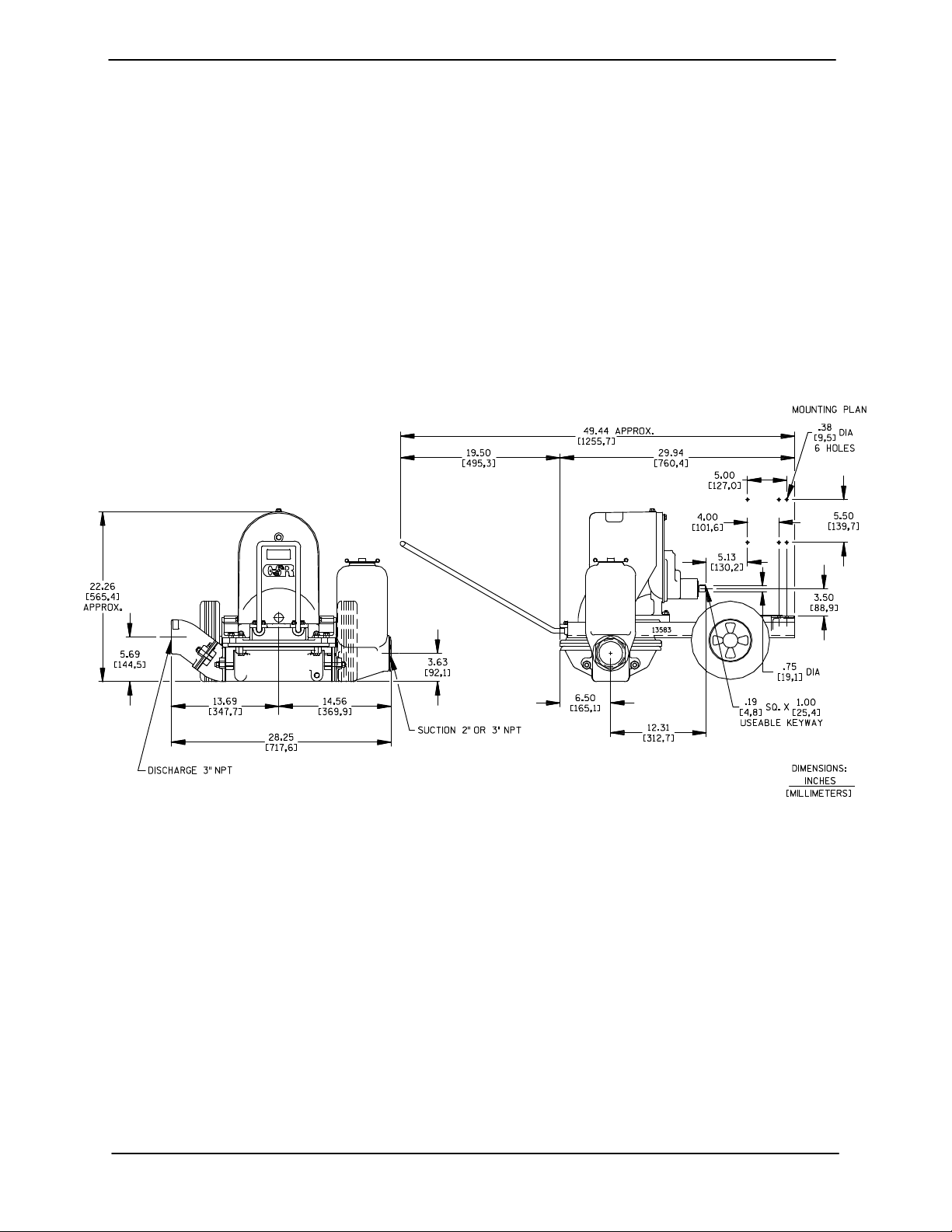
OUTLINE DRAWING
For further assistance, contact your Gorman-Rupp
distributor or the Gorman-Rupp Company.
Pump Dimensions
See Figure 1 for the approximate physical dimensions of this pump.
Figure 1. Pump Model 3D-B
PREINSTALLATION INSPECTION
The pump assembly was inspected and tested before shipment from the factory. Before installation,
inspect the pump for damage which may have occurred during shipment. Check as follows:
a. Inspect the pump for cracks, dents, damaged
threads, and other obvious damage.
b. Check for and tighten loose attaching hard-
ware. Since gaskets tend to shrink after drying, check for loose hardware at mating surfaces.
c. Carefully read all tags, decals, and markings
on the pump assembly, and perform all duties
indicated.
d. Check levels and lubricate as necessary. Re-
fer to LUBRICATION in the MAINTENANCE
AND REPAIR section of this manual and perform duties as instructed.
e. If the pump and motor have been stored for
more than 12 months, some of the components or lubricants may have exceeded their
maximum shelf life. These must be inspected
or replaced to ensure maximum pump service.
PAGE B − 1INSTALLATION

OM−01490 D SERIES
If the maximum shelf life has been exceeded, or if
anything appears to be abnormal, contact your
Gorman-Rupp distributor or the factory to determine the repair or updating policy. Do not put the
pump into service until appropriate action has
been taken.
ELECTRIC MOTOR INSTALLATION
The pump is designed to be flex-coupled to a 1750
RPM synchronous speed electric motor. The pump
base will accept either a 143T or 145T motor frame.
Be sure the motor to be used meets these specifications and is compatible with the intended application.
Install and operate only an explosion
proof motor in an explosive atmosphere. Install, connect, and operate
the motor in accordance with the National Electric Code and all local codes.
If there is a conflict between the instructions in the manual accompanying the
unit and the National Electric Code or
the applicable local code, the National
or local code shall take precedence.
POSITIONING PUMP
and move the unit are improperly wrapped
around the pump.
Mounting
Locate the pump in an accessible place as close as
practical to the liquid being pumped. Level mounting is essential for proper operation.
The pump may have to be supported or shimmed
to provide for level operation or to eliminate vibration.
After the pump has been positioned, block the
wheels and secure the pump to prevent creeping.
SUCTION AND DISCHARGE PIPING
Pump performance is adversely effected by increased suction lift, discharge elevation, and friction losses. See Page E-1 to be sure your overall
application allows the pump to operate within the
safe operation range.
Materials
Either pipe or hose maybe used for suction and
discharge lines; however, the materials must be
compatible with the liquid being pumped. If hose is
used in suction lines, it must be the rigid-wall, reinforced type to prevent collapse under suction. Using piping couplings in suction lines is not recommended.
Lifting
Line Configuration
Pump unit weights will vary depending on the
mounting and drive provided. Check the shipping
tag on the unit packaging for the actual weight, and
use lifting equipment with appropriate capacity.
Drain the pump and remove all customer-installed
equipment such as suction and discharge hoses
or piping before attempting to lift existing, installed
units.
The pump assembly can be seriously
damaged if the cables or chains used to lift
PAGE B − 2 INSTALLATION
Keep suction and discharge lines as straight as
possible to minimize friction losses. Make minimum use of elbows and fittings, which substantially increase friction loss. If elbows are necessary,
use the long-radius type to minimize friction loss.
Never pull a line into place by tightening connections at the pump. Lines near the pump must be independently supported to avoid strain on the
pump which could cause excessive vibration and
increased diaphragm and gear train wear. If hosetype lines are used, they should have adequate
support to secure them when filled with liquid and
under pressure.
D SERIES OM−01490
Fixed, Rigid Piping
This pump is equipped with an integral suction accumulator chamber which promotes an efficient
flow of liquid and acts as an air cushion against
shock. Since the air in this chamber will leak away
during pump operation, the air must be replenished periodically. To introduce air into the chamber, stop the pump and remove the suction accumulator plug and integral gasket; this will break
prime and allow the liquid in the chamber to drain
away through the suction line.
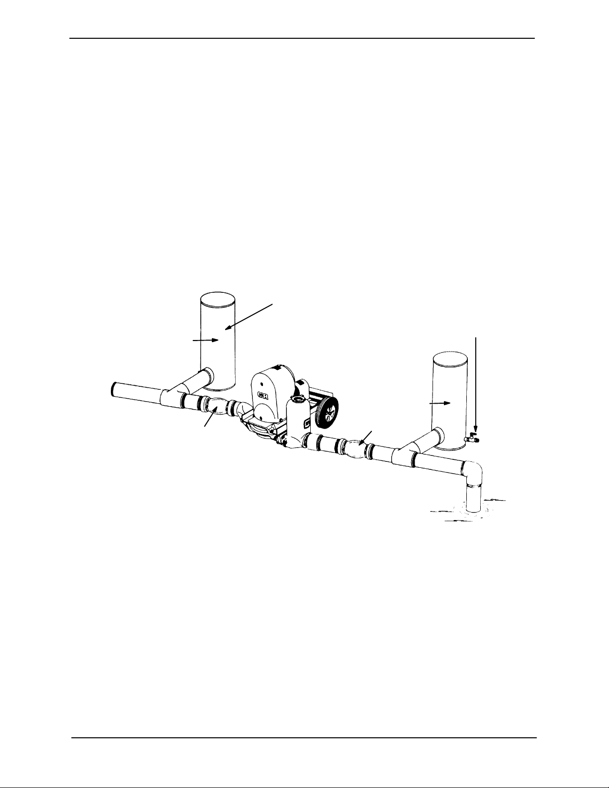
AIR CHAMBERS
(18 TO 24 INCH LENGTHS OF
6 TO 8 INCH DIAMETER PIPE
WITH WELDED CAPS)
DISCHARGE
CHAMBER
If the pump is mounted in a system with fixed, rigid
piping, it is recommended that a flexible connection be installed at or near the suction and discharge ports to absorb shock which would otherwise be transmitted through the drive train and
greatly accelerate pump wear.
In a fixed piping installation, properly sized surge
suppressors must be installed in both suction and
discharge lines. If commercial surge suppressors
are not readily available, air chambers may be fabricated from pipe as shown in Figure 2.
1/2-INCH VALVE FOR
RECHARGING AIR
CHAMBER WITH
COMPRESSED AIR
(ALSO ON DISCHARGE
CHAMBER)
DISCHARGE
FLEXIBLE JOINT
NOTE: INSTALL AIR CHAMBERS OFF FLOW LINE TEES
TO AVOID SURFACE TURBULENCE WITHIN CHAMBERS.
Figure 2. Fixed Piping Installation
Note that the air chambers have not been installed
directly in the flow line, but have been installed off
tees to avoid turbulence within the chambers. The
air chambers are fitted with valves to permit introduction of small amounts of compressed air to further dampen shock; this compressed air will leak
away during operation, and should be replaced
from time to time. If the suction chamber floods,
open the suction chamber valve to break prime
and allow the liquid in chamber to drain through
the suction line.
SUCTION
CHAMBER
FLEXIBLE JOINT
SUCTION
Gauges
If discharge pressure and vacuum suction gauges
are desired, drill and tap the suction and discharge
lines not less than 18 inches (457,2 mm) from the
suction and discharge ports and install the lines.
Installation closer to the pump may result in erratic
readings.
PAGE B − 3INSTALLATION
 Loading...