

Page 1
OM-01477-04
September 13, 2010
INSTALLATION, OPERATION,
AND MAINTENANCE MANUAL
WITH PARTS LIST
D SERIES PUMP
MODEL
2D−E.50 3P
THE GORMAN-RUPP COMPANY D MANSFIELD, OHIO
www.grpumps.com
GORMAN-RUPP OF CANADA LIMITED D ST. THOMAS, ONTARIO, CANADA Printed in U.S.A.
e2010 The Gorman-Rupp Company
Page 2

Register your new
Gorman-Rupp pump online at
www.grpumps.com
Valid serial number and e-mail address required.
RECORD YOUR PUMP MODEL AND SERIAL NUMBER
Please record your pump model and serial number in the
spaces provided below. Your Gorman-Rupp distributor
needs this information when you require parts or service.
Pump Model:
Serial Number:
Page 3

TABLE OF CONTENTS
INTRODUCTION PAGE I − 1. . . . . . . . . . . . . . . . . . . . . . . . . . . . . . . . . . . . . . . . . . . . . . . . . . .
SAFETY - SECTION A PAGE A − 1. . . . . . . . . . . . . . . . . . . . . . . . . . . . . . . . . . . . . . . . . . . . .
INSTALLATION − SECTION B PAGE B − 1. . . . . . . . . . . . . . . . . . . . . . . . . . . . . . . . . . . . .
Pump Dimensions PAGE B − 1. . . . . . . . . . . . . . . . . . . . . . . . . . . . . . . . . . . . . . . . . . . . . . . . . . . . . . . .
PREINSTALLATION INSPECTION PAGE B − 1. . . . . . . . . . . . . . . . . . . . . . . . . . . . . . . . . . . . . . . . . . . . . . .
POSITIONING PUMP PAGE B − 2. . . . . . . . . . . . . . . . . . . . . . . . . . . . . . . . . . . . . . . . . . . . . . . . . . . . . . . . . .
Lifting PAGE B − 2. . . . . . . . . . . . . . . . . . . . . . . . . . . . . . . . . . . . . . . . . . . . . . . . . . . . . . . . . . . . . . . . . . . .
Mounting PAGE B − 2. . . . . . . . . . . . . . . . . . . . . . . . . . . . . . . . . . . . . . . . . . . . . . . . . . . . . . . . . . . . . . . .
SUCTION AND DISCHARGE PIPING PAGE B − 2. . . . . . . . . . . . . . . . . . . . . . . . . . . . . . . . . . . . . . . . . . . .
Materials PAGE B − 2. . . . . . . . . . . . . . . . . . . . . . . . . . . . . . . . . . . . . . . . . . . . . . . . . . . . . . . . . . . . . . . . .
Line Configuration PAGE B − 2. . . . . . . . . . . . . . . . . . . . . . . . . . . . . . . . . . . . . . . . . . . . . . . . . . . . . . . . .
Fixed, Rigid Piping PAGE B − 2. . . . . . . . . . . . . . . . . . . . . . . . . . . . . . . . . . . . . . . . . . . . . . . . . . . . . . . .
Gauges PAGE B − 3. . . . . . . . . . . . . . . . . . . . . . . . . . . . . . . . . . . . . . . . . . . . . . . . . . . . . . . . . . . . . . . . . .
SUCTION LINES PAGE B − 3. . . . . . . . . . . . . . . . . . . . . . . . . . . . . . . . . . . . . . . . . . . . . . . . . . . . . . . . . . . . . .
Fittings PAGE B − 4. . . . . . . . . . . . . . . . . . . . . . . . . . . . . . . . . . . . . . . . . . . . . . . . . . . . . . . . . . . . . . . . . .
Strainers PAGE B − 4. . . . . . . . . . . . . . . . . . . . . . . . . . . . . . . . . . . . . . . . . . . . . . . . . . . . . . . . . . . . . . . . .
Sealing PAGE B − 4. . . . . . . . . . . . . . . . . . . . . . . . . . . . . . . . . . . . . . . . . . . . . . . . . . . . . . . . . . . . . . . . . .
DISCHARGE LINES PAGE B − 4. . . . . . . . . . . . . . . . . . . . . . . . . . . . . . . . . . . . . . . . . . . . . . . . . . . . . . . . . . .
Siphoning PAGE B − 4. . . . . . . . . . . . . . . . . . . . . . . . . . . . . . . . . . . . . . . . . . . . . . . . . . . . . . . . . . . . . . . .
Valves PAGE B − 4. . . . . . . . . . . . . . . . . . . . . . . . . . . . . . . . . . . . . . . . . . . . . . . . . . . . . . . . . . . . . . . . . . .
ELECTRICAL CONNECTIONS PAGE B − 4. . . . . . . . . . . . . . . . . . . . . . . . . . . . . . . . . . . . . . . . . . . . . . . . . .
OPERATION − SECTION C PAGE C − 1. . . . . . . . . . . . . . . . . . . . . . . . . . . . . . . . . . . . . . .
STARTING PAGE C − 1. . . . . . . . . . . . . . . . . . . . . . . . . . . . . . . . . . . . . . . . . . . . . . . . . . . . . . . . . . . . . . . . . . .
OPERATION PAGE C − 1. . . . . . . . . . . . . . . . . . . . . . . . . . . . . . . . . . . . . . . . . . . . . . . . . . . . . . . . . . . . . . . . .
Priming PAGE C − 1. . . . . . . . . . . . . . . . . . . . . . . . . . . . . . . . . . . . . . . . . . . . . . . . . . . . . . . . . . . . . . . . . .
OPERATION CHECKS PAGE C − 1. . . . . . . . . . . . . . . . . . . . . . . . . . . . . . . . . . . . . . . . . . . . . . . . . . . . . . . . .
Gearbox Check PAGE C − 1. . . . . . . . . . . . . . . . . . . . . . . . . . . . . . . . . . . . . . . . . . . . . . . . . . . . . . . . . . .
Leakage Check PAGE C − 1. . . . . . . . . . . . . . . . . . . . . . . . . . . . . . . . . . . . . . . . . . . . . . . . . . . . . . . . . . .
Strainer Check PAGE C − 1. . . . . . . . . . . . . . . . . . . . . . . . . . . . . . . . . . . . . . . . . . . . . . . . . . . . . . . . . . . .
STOPPING PAGE C − 2. . . . . . . . . . . . . . . . . . . . . . . . . . . . . . . . . . . . . . . . . . . . . . . . . . . . . . . . . . . . . . . . . . .
Cold Weather Preservation PAGE C − 2. . . . . . . . . . . . . . . . . . . . . . . . . . . . . . . . . . . . . . . . . . . . . . . . .
GEARBOX TEMPERATURE CHECK PAGE C − 2. . . . . . . . . . . . . . . . . . . . . . . . . . . . . . . . . . . . . . . . . . . . .
TROUBLESHOOTING − SECTION D PAGE D − 1. . . . . . . . . . . . . . . . . . . . . . . . . . . . . . .
PUMP MAINTENANCE AND REPAIR - SECTION E PAGE E − 1. . . . . . . . . . . . . . . . . .
STANDARD PERFORMANCE CHART PAGE E − 1. . . . . . . . . . . . . . . . . . . . . . . . . . . . . . . . . . . . . . . . . . .
PARTS LISTS:
Pump Model PAGE E − 3. . . . . . . . . . . . . . . . . . . . . . . . . . . . . . . . . . . . . . . . . . . . . . . . . . . . . . . . . . . . .
Plunger Rod Assembly PAGE E − 5. . . . . . . . . . . . . . . . . . . . . . . . . . . . . . . . . . . . . . . . . . . . . . . . . . . .
PUMP DISASSEMBLY AND REASSEMBLY PAGE E − 6. . . . . . . . . . . . . . . . . . . . . . . . . . . . . . . . . . . . . . .
Suction And Discharge Check Valve Removal PAGE E − 6. . . . . . . . . . . . . . . . . . . . . . . . . . . . . . . .
Diaphragm and Plunger Rod Removal PAGE E − 6. . . . . . . . . . . . . . . . . . . . . . . . . . . . . . . . . . . . . . .
i
Page 4

TABLE OF CONTENTS
(continued)
Plunger Rod and Diaphragm Removal PAGE E − 7. . . . . . . . . . . . . . . . . . . . . . . . . . . . . . . . . . . . . . .
Suction And Discharge Check Valve Installation PAGE E − 7. . . . . . . . . . . . . . . . . . . . . . . . . . . . . .
LUBRICATION PAGE E − 8. . . . . . . . . . . . . . . . . . . . . . . . . . . . . . . . . . . . . . . . . . . . . . . . . . . . . . . . . . . . . . . .
Plunger Rod Assembly PAGE E − 8. . . . . . . . . . . . . . . . . . . . . . . . . . . . . . . . . . . . . . . . . . . . . . . . . . . .
Gear Reducer PAGE E − 8. . . . . . . . . . . . . . . . . . . . . . . . . . . . . . . . . . . . . . . . . . . . . . . . . . . . . . . . . . . .
ii
Page 5
D SERIES
OM−01477
INTRODUCTION
Thank You for purchasing a Gorman-Rupp pump.
Read this manual carefully to learn how to safely
install and operate your pump. Failure to do so
could result in personal injury or damage to the
pump.
This is a D Series, positive displacement pump,
utilizing a single-action diaphragm to produce a
straight-through flow of liquid. The pump is flexcoupled to a 1/2 HP electric motor. It is ideally
suited to industrial and contractor’s applications
since it will handle liquids ranging from clear water
to construction-site muck. The basic material of
construction for wetted parts is aluminum, with
neoprene flap valves and diaphragm.
Because pump installations are seldom identical,
this manual cannot possibly provide detailed instructions and precautions for every aspect of
each specific application. Therefore, it is the responsibility of the owner/installer of the pump to
ensure that applications not addressed in this
manual are performed only after establishing that
neither operator safety nor pump integrity are compromised by the installation. Pumps and related
equipment must be installed and operated according to all national, local and industry standards.
For information or technical assistance on the engine, contact the engine manufacturer’s local
dealer or representative.
The following are used to alert maintenance personnel to procedures which require special attention, to those which could damage equipment, and
to those which could be dangerous to personnel:
Immediate hazards which WILL result in
severe personal injury or death. These
instructions describe the procedure required and the injury which will result
from failure to follow the procedure.
Hazards or unsafe practices which
COULD result in severe personal injury
or death. These instructions describe
the procedure required and the injury
which could result from failure to follow
the procedure.
If there are any questions regarding the pump or
its application which are not covered in this manual or in other literature accompanying this unit,
please contact your Gorman-Rupp distributor, or:
The Gorman-Rupp Company
P.O. Box 1217
Mansfield, Ohio 44901−1217
Phone: (419) 755−1011
or:
Gorman-Rupp of Canada Limited
70 Burwell Road
St. Thomas, Ontario N5P 3R7
Phone: (519) 631−2870
Hazards or unsafe practices which COULD
result in minor personal injury or product
or property damage. These instructions
describe the requirements and the possible damage which could result from failure
to follow the procedure.
NOTE
Instructions to aid in installation, operation,and
maintenance, or which clarify a procedure.
PAGE I − 1INTRODUCTION
Page 6
D SERIES
SAFETY - SECTION A
This information applies to D Series
electric motor driven diaphragm
pumps. Refer to the manual accompanying the motor before attempting to
begin operation.
Before attempting to open or service the
pump:
1. Familiarize yourself with this manual.
2. Lock out and tag out incoming
power to the motor to ensure that
the pump will remain inoperative.
3. Allow the pump to completely cool
if overheated.
4. Drain the pump.
This pump is designed to handle non-
volatile non-flammable liquids containing specified entrained solids. Do not
attempt to pump volatile, corrosive, or
flammable liquids which may damage
the pump or endanger personnel as a
result of pump failure.
After the pump has been installed, block
the wheels and secure the pump to prevent creeping. Make certain that the
pump and all piping or hose connections are tight, properly supported and
secure before operation.
OM−01477
All electrical connections must be in accordance with the National Electric
Code. If there is a conflict between instructions provided and N.E.C. specifications, N.E.C. specifications shall take
precedence. All electrical equipment
supplied with this pump was in conformance with N.E.C. requirements in effect on the date of manufacture. Failure
to follow applicable specifications, or
substitution of electrical parts not supplied or approved by the manufacturer,
can result in severe injury or death.
Do not operate the pump without the eccentric and coupling guards in place
over the rotating parts. Exposed rotating parts can catch clothing, fingers, or
tools, causing severe injury to personnel.
The electrical power used to operate
this pump is high enough to cause injury or death. Obtain the services of a
qualified electrician to make all electrical connections. Make certain the pump
and motor are properly grounded; never
use gas pipe as an electrical ground. Be
sure that the incoming power matches
the voltage and phase of the motor before making motor connections. Do not
run the pump if the voltage is not within
limits.
PAGE A − 1SAFETY
Page 7

Do not install and operate a non-explosion proof motor in an explosive atmosphere. Install, connect, and operate
the motor in accordance with The National Electric Code and all local codes.
If there is a conflict between the instructions in the manual accompanying the
unit and The National Electric Code or
the applicable local code, The National
or local code shall take precedence.
D SERIESOM−01477
Never install a positive shut-off valve in the
discharge line; discharge restrictions will
cause excessive friction loss resulting in
overloading and destruction of pump and
drive components. It is strongly recommended that unless absolutely necessary,
no positive shut-off valve be installed in the
suction line; excessive restriction will
cause incomplete filling of the diaphragm
chamber and result in shortened diaphragm life.
PAGE A − 2 SAFETY
Page 8
D SERIES OM−01477
INSTALLATION − SECTION B
Review all SAFETY information in Section A.
Since pump installations are seldom identical, this
section offers only general recommendations and
practices required to inspect, position, and arrange the pump and piping.
OUTLINE DRAWING
For further assistance, contact your Gorman-Rupp
distributor or the Gorman-Rupp Company.
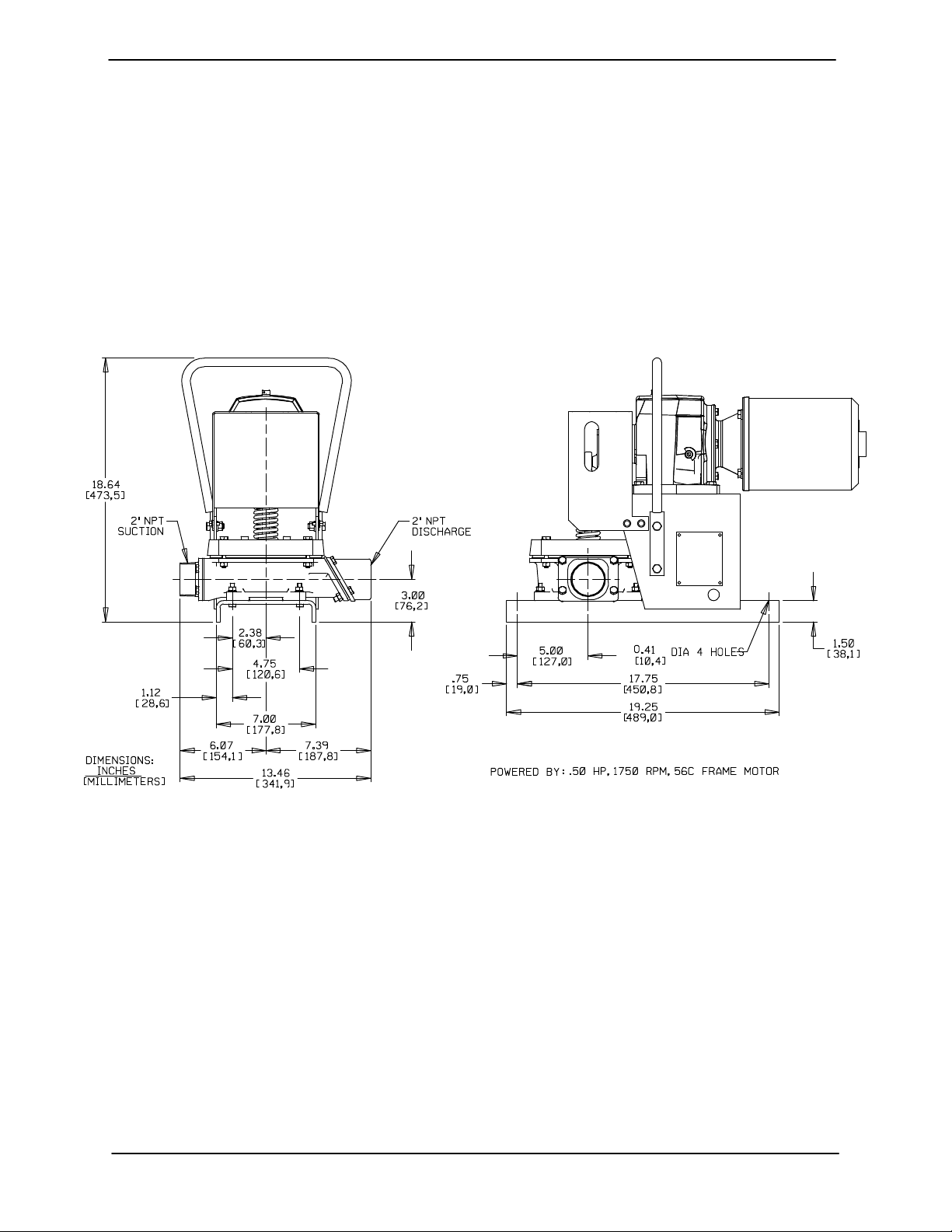
Pump Dimensions
See Figure 1 for the approximate physical dimensions of this pump.
Figure 1. Pump Model 2D-E.50 3P
PREINSTALLATION INSPECTION
The pump assembly was inspected and tested before shipment from the factory. Before installation,
inspect the pump for damage which may have occurred during shipment. Check as follows:
a. Inspect the pump for cracks, dents, damaged
threads, and other obvious damage.
b. Check for and tighten loose attaching hard-
ware. Since gaskets tend to shrink after drying, check for loose hardware at mating surfaces.
c. Carefully read all tags, decals, and markings
on the pump assembly, and perform all duties
indicated.
d. Check levels and lubricate as necessary. Re-
move the shipping plug from the top of the
gear reducer and replace it with the vented
plug shipped loose with the unit. Refer to LU-
BRICATION in the MAINTENANCE AND REPAIR section of this manual and perform du-
ties as instructed.
e. If the pump and motor have been stored for
more than 12 months, some of the compo-
PAGE B − 1INSTALLATION
Page 9

OM−01477 D SERIES
nents or lubricants may have exceeded their
maximum shelf life. These must be inspected
or replaced to ensure maximum pump service.
If the maximum shelf life has been exceeded, or if
anything appears to be abnormal, contact your
Gorman-Rupp distributor or the factory to determine the repair or updating policy. Do not put the
pump into service until appropriate action has
been taken.
POSITIONING PUMP
Do not install and operate a non-explosion proof motor in an explosive atmosphere.
Lifting
The pump may have to be supported or shimmed
to provide for level operation or to eliminate vibration.
After the pump has been positioned, block the
wheels and secure the pump to prevent creeping.
SUCTION AND DISCHARGE PIPING
Pump performance is adversely effected by increased suction lift, discharge elevation, and friction losses. See Page E-1 to be sure your overall
application allows the pump to operate within the
safe operation range.
Materials
Either pipe or hose maybe used for suction and
discharge lines; however, the materials must be
compatible with the liquid being pumped. If hose is
used in suction lines, it must be the rigid-wall, reinforced type to prevent collapse under suction. Using piping couplings in suction lines is not recommended.
Pump unit weights will vary depending on the
mounting and drive provided. Check the shipping
tag on the unit packaging for the actual weight, and
use lifting equipment with appropriate capacity.
Drain the pump and remove all customer-installed
equipment such as suction and discharge hoses
or piping before attempting to lift existing, installed
units.
The pump assembly can be seriously
damaged if the cables or chains used to lift
and move the unit are improperly wrapped
around the pump.
Mounting
Locate the pump in an accessible place as close as
practical to the liquid being pumped. Level mounting is essential for proper operation.
Line Configuration
Keep suction and discharge lines as straight as
possible to minimize friction losses. Make minimum use of elbows and fittings, which substantially increase friction loss. If elbows are necessary,
use the long-radius type to minimize friction loss.
Never pull a line into place by tightening connections at the pump. Lines near the pump must be independently supported to avoid strain on the
pump which could cause excessive vibration and
increased diaphragm and gear train wear. If hosetype lines are used, they should have adequate
support to secure them when filled with liquid and
under pressure.
Fixed, Rigid Piping
This pump is equipped with an integral suction accumulator chamber which promotes an efficient
flow of liquid and acts as an air cushion against
shock. Since the air in this chamber will leak away
PAGE B − 2 INSTALLATION
Page 10

D SERIES OM−01477
during pump operation, the air must be replenished periodically. To introduce air into the chamber, stop the pump and remove the suction accumulator plug and integral gasket; this will break
prime and allow the liquid in the chamber to drain
away through the suction line.
If the pump is mounted in a system with fixed, rigid
piping, it is recommended that a flexible connection be installed at or near the suction and dis-
AIR CHAMBERS
(18 TO 24 INCH LENGTHS OF
6 TO 8 INCH DIAMETER PIPE
WITH WELDED CAPS)
DISCHARGE
CHAMBER
DISCHARGE
FLEXIBLE JOINT
charge ports to absorb shock which would otherwise be transmitted through the drive train and
greatly accelerate pump wear.
In a fixed piping installation, properly sized surge
suppressors must be installed in both suction and
discharge lines. If commercial surge suppressors
are not readily available, air chambers may be fabricated from pipe as shown in Figure 2.
1/2-INCH VALVE FOR
RECHARGING AIR
CHAMBER WITH
COMPRESSED AIR
(ALSO ON DISCHARGE
CHAMBER)
SUCTION
CHAMBER
FLEXIBLE JOINT
NOTE: INSTALL AIR CHAMBERS OFF FLOW LINE TEES
TO AVOID SURFACE TURBULENCE WITHIN CHAMBERS.
Figure 2. Fixed Piping Installation
Note that the air chambers have not been installed
directly in the flow line, but have been installed off
tees to avoid turbulence within the chambers. The
air chambers are fitted with valves to permit introduction of small amounts of compressed air to further dampen shock; this compressed air will leak
away during operation, and should be replaced
from time to time. If the suction chamber floods,
open the suction chamber valve to break prime
and allow the liquid in chamber to drain through
the suction line.
Gauges
If discharge pressure and vacuum suction gauges
are desired, drill and tap the suction and discharge
lines not less than 18 inches (457,2 mm) from the
SUCTION
suction and discharge ports and install the lines.
Installation closer to the pump may result in erratic
readings.
SUCTION LINES
To avoid air pockets which could affect pump priming, the suction line must be as short and direct as
possible. When operation involves a suction lift, the
line must always slope upward to the pump from
the source of the liquid being pumped; if the line
slopes down to the pump at any point along the
suction run, air pockets will be created.
NOTE
Maximum pump performance is realized at suction
lifts of 5 feet (1,5 m) or less. Use the shortest possi-
PAGE B − 3INSTALLATION
Page 11

OM−01477 D SERIES
ble length of suction hose or piping; lengths of 25
feet (7,6 m) or longer will reduce the capacity of the
pump.
It is strongly recommended that no positive shutoff valve be installed in the suction line; excessive
restrictions will cause incomplete filling of the diaphragm chamber and result in short diaphragm
life.
Fittings
Suction lines should be the same size as the pump
inlet. If reducers are used in suction lines, they
should be the eccentric type, and should be installed with the flat part of the reducers uppermost
to avoid creating air pockets. The suction line
should not be restricted more than 1 inch below the
nominal suction size.
The use of pipe couplings in the suction line is not
recommended.
Strainers
pipe dope. The pipe dope should be compatible
with the liquid being pumped.
DISCHARGE LINES
The discharge line must be the same size
as, or larger than, the suction line. Never install or operate the pump with a discharge
line smaller than the suction; a restricted
discharge line will cause excessive friction
loss resulting in overloading and destruction of pump and drive components.
Siphoning
Do not terminate the discharge line at a level lower
than that of the liquid being pumped unless a siphon breaker is used in the line. Otherwise, a siphoning action causing damage to the pump
could result.
If a strainer is furnished with the pump, be certain
to use it; any spherical solids which pass through a
strainer furnished with the pump will also pass
through the pump itself.
If a strainer is not furnished with the pump, but is
installed by the pump user, make certain that the
total area of the openings in the strainer is at least
three or four times the cross section of the suction
line, and that the openings will not permit passage
of solids larger than the solids handling capability
of the pump.
This pump is designed to handle up to 1-1/2 inch
(38,1 mm) diameter spherical solids.
Sealing
Since even a slight leak will affect priming, head,
and capacity, especially when operating with a
high suction lift, all connections in the suction line
should be sealed with pipe dope to ensure an airtight seal. Follow the sealant manufacturer’s recommendations when selecting and applying the
Valves
The pump is provided with integral suction and discharge check valves.
Never install a positive shut-off valve in the
discharge line; discharge restrictions will
cause excessive friction loss resulting in
overloading and destruction of pump and
drive components. It is strongly recommended that unless absolutely necessary,
no positive shut-off valve be installed in the
suction line; excessive restriction will
cause incomplete filling of the diaphragm
chamber and result in shortened diaphragm life.
ELECTRICAL CONNECTIONS
Before connecting the motor to the incoming
power, check that the electrical service available
PAGE B − 4 INSTALLATION
Page 12

D SERIES OM−01477
matches the pump motor requirements stamped
on the motor nameplate.
Do not install and operate a non-explosion proof motor in an explosive atmo-
The electrical power used to operate
this pump is high enough to cause injury or death. Obtain the services of a qualified electrician to make all electrical
connections. Make certain the pump
and motor are properly grounded; never
use gas pipe as an electrical ground. Be
sure that the incoming power matches
the voltage and phase of the motor be-
sphere. Install, connect, and operate
the motor in accordance with The National Electric Code and all local codes.
If there is a conflict between the instructions in the manual accompanying the
unit and The National Electric Code or
the applicable local code, The National
or local code shall take precedence.
fore making motor connections. Do not
run the pump if the voltage is not within
limits.
Refer to the following motor data before making
electrical connections.
MODEL
2D−E.50 3P
Motor Data
VOLTAGE PHASE HP Hz RPM
230/460 3 .50 60 1750
PAGE B − 5INSTALLATION
Page 13

D SERIES
OM−01477
OPERATION − SECTION C
Review all SAFETY information in Section A.
Follow the instructions on all tags, labels and
decals attached to the pump.
This pump is designed to handle non-
volatile non-flammable liquids containing specified entrained solids. Do not
attempt to pump volatile, corrosive, or
flammable liquids which may damage
the pump or endanger personnel as a
result of pump failure.
After the pump has been installed, block
the wheels and secure the pump to prevent creeping. Make certain that the
pump and all piping or hose connections are tight, properly supported and
secure before operation.
Pump application will affect its performance, especially discharge velocities. Consult the GormanRupp factory for actual performance levels for the
pump.
ened diaphragm life. No positive shut-off
valve should be installed in the discharge
line.
STARTING
Consult the operations manual furnished with the
motor before starting the pump. Open any valves
installed in the suction line and start the pump.
OPERATION
Priming
The pump may not prime immediately because the
suction line must first fill with liquid. If the pump fails
to prime within five minutes, stop the engine and
check the suction line for leaks.
OPERATION CHECKS
Gearbox Check
Check that the gearbox is properly lubricated (see
LUBRICATION in MAINTENANCE AND REPAIR).
Install the pump and piping as described in INSTALLATION. Make sure that the piping connec-
tions are tight, and that the pump is securely
mounted. Check that components are properly lubricated (see LUBRICATION in MAINTENANCE
AND REPAIR).
Make certain that any positive shut-off
valve installed in the suction line is open
before operating the pump; excessive restriction will cause incomplete filling of the
diaphragm chamber and result in short-
OPERATION PAGE C − 1
Leakage Check
No leakage should be visible at pump mating surfaces, connections or fittings. Keep all line connections and fittings tight to maintain maximum pump
efficiency.
Strainer Check
If a suction strainer has been installed, check and
clean it as necessary. It should be cleaned if pump
flow begins to drop. If a vacuum suction gauge has
been installed, monitor and record the readings
regularly to detect strainer blockage.
Page 14

OM−01477 D SERIES
STOPPING
After stopping the pump, lock out and tag out incoming power to the motor to ensure that the
pump will remain inoperative.
If the pump will be idle for more than a few hours, or
if it has been pumping liquids containing a large
amount of solids, flush it with clean water.
Cold Weather Preservation
The primary construction materials of this
pump are aluminum, with neoprene flap
valves and diaphragm. Do not attempt to
clean or flush this pump with any liquid
which would attack pump fittings or components. Avoid cleaning with cleaning solvent.
In below freezing conditions, drain the water from
the pump and the lines when the pump is not in op-
eration. Also, clean out any solids by flushing with a
hose.
GEARBOX TEMPERATURE CHECK
The gearbox runs higher than ambient temperatures because of heat generated by friction. Temperatures of approximately 200_F (93_C) are con-
sidered normal, and can operate intermittently at
250_F (121_C).
Checking gearbox temperatures by hand is inaccurate. Place a contact-type thermometer against
the housing and record this temperature for future
reference.
A sudden increase in gearbox temperature is a
warning that the bearings are at the point of failing.
Make certain that the bearing lubricant is of the
proper viscosity and at the correct level (see LU-
BRICATION in Section E). Bearing overheating
can also be caused by shaft misalignment and/or
excessive vibration.
When pumps are first started, the bearings may
seem to run at temperatures above normal. Continued operation should bring the temperatures
down to normal levels.
OPERATIONPAGE C − 2
Page 15

D SERIES OM−01477
TROUBLESHOOTING − SECTION D
Review all SAFETY information in Section A.
Before attempting to open or service
the pump:
1. Familiarize yourself with this manual.
2. Lock out and tag out incoming
power to ensure that the pump will
remain inoperative.
3. Allow the pump to completely cool
if overheated.
4. Drain the pump.
TROUBLE POSSIBLE CAUSE PROBABLE REMEDY
PUMP FAILS TO
PRIME
PUMP STOPS OR
FAILS TO DELIVER
RATED FLOW OR
PRESSURE
Air leak in suction line. Correct leak.
Lining of suction hose collapsed. Replace suction hose.
Integral suction or discharge check Clean valves, check that flange nuts
valve clogged, binding, or not seating are tight.
properly.
Cracked or broken diaphragm. Replace diaphragm.
Diaphragm not securely in place. Secure diaphragm.
Strainer clogged. Check strainer and clean if necessary.
Air leak in suction line. Correct leak.
Suction intake not properly submerged. Check installation.
Lining of suction hose collapsed. Replace suction hose.
Cracked or broken diaphragm. Replace diaphragm.
Diaphragm not securely in place. Secure diaphragm.
Strainer clogged. Check strainer and clean if necessary.
Integral suction or discharge check Clean valves, check that flange nuts
valve clogged, binding, or not seating are tight.
properly.
TROUBLESHOOTING PAGE D − 1
Page 16

OM−01477 D SERIES
TROUBLE POSSIBLE CAUSE PROBABLE REMEDY
PUMP REQUIRES
TOO MUCH
POWER
PUMP CLOGS
FREQUENTLY
EXCESSIVE NOISE
BEARINGS RUN
TOO HOT
Liquid solution too thick. Dilute if possible.
Integral discharge check valve clogged Clean valve.
or binding.
Bearings in motor or gearbox Check bearings.
worn or binding.
Integral suction or discharge check Clean valves, check that flange nuts
valve clogged, binding, or not seating are tight.
properly.
Liquid solution too thick. Dilute if possible.
Pump, gearbox, or motor not Check and tighten mounting bolts.
securely mounted.
Gearbox or motor not properly See LUBRICATION in MAINTE-
lubricated. NANCE AND REPAIR.
Bearing temperature is high, but within Check bearing temperature regularly
limits. to monitor any increase.
Low or incorrect lubricant. Check for proper type and level of
lubricant.
Drive misaligned. Align drive properly.
TROUBLESHOOTINGPAGE D − 2
Page 17

D SERIES OM−01477
PUMP MAINTENANCE AND REPAIR - SECTION E
MAINTENANCE AND REPAIR OF THE WEARING PARTS OF THE PUMP WILL MAINTAIN PEAK
OPERATING PERFORMANCE.
IN GALLONS PER MINUTE AT 60 STROKES PER MINUTE
STATIC
LIFT
IN FEET
5272624 22
15
IN LITERS PER MINUTE AT 60 STROKES PER MINUTE
STATIC
LIFT
IN METERS
3,0
4,6 68,1
6,1 64,3
STANDARD PERFORMANCE TEST DATA FOR 2D ELECTRIC MOTOR DRIVEN PUMP
0
2510 24 21 20
21 20
0
102,2 98,4 90,8 83,31,5
94,6 90,8 79,5 75,7
79,5 75,7 71,9 68,1
STATIC DISCHARGE HEAD IN FEET
510 15 20
20
19
19202122
1920 18
STATIC DISCHARGE HEAD IN METERS
1,5 3,0 4,6 6,1
75,779,583,3
71,9
18
17
75,7
71,9
Based on 70_ F (21_ C) clear water at sea level
with minimum suction lift, using 2 inch (50 mm)
suction hose and 2 inch (50 mm) non-collapsible
discharge hose. Since pump installations are seldom identical, your performance may be difference due to such factors as specific gravity, eleva-
MAINTENANCE & REPAIR PAGE E − 1
tion and temperature.
If your pump serial number is followed by an N",
your pump is NOT a standard production model.
Contact the Gorman-Rupp Company to verify performance or part numbers.
Page 18

PARTS PAGE
D SERIESOM−01477
SECTION DRAWING
Figure 1. 2D−E.50 3P Pump Model
MAINTENANCE & REPAIRPAGE E − 2
Page 19

D SERIES OM−01477
PARTS LIST
2D−E.50 3P Pump Model
(From S/N 1467825 Up)
If your pump serial number is followed by an N", your pump is NOT a standard production model. Contact
the Gorman-Rupp Company to verify part numbers.
ITEM
NO.
1 MOTOR 28211−540 −−− 1
2 HEX HEAD CAP SCREW B0604 15991 8
3 LOCK WASHER J06 15991 12
4 CARRYING HANDLE ASSY 44724−007 24150 1
5 VENTED PIPE PLUG 4823 15079 1
6 SHIPPING PLUG 11495 15079 1
7 GEAR HEAD REDUCER 24572−011 −−− 1
8 ROTATION DECAL 2613BM −−− 1
9 PLUNGER ROD LUBRICATION DECAL 38816−085 −−− 1
10 PLUNGER ROD ASSEMBLY 46181−004 −−− 1
11 RETAINING RING 26812−702 −−− 1
12 KEY N0403 15990 1
13 ECCENTRIC GUARD ASSY 42381−140 24150 1
14 HEX HEAD CAP SCREW B0605 15991 4
15 HEX NUT D06 15991 8
16 HEX HEAD CAP SCREW B0508 15991 4
17 HEX NUT D05 15991 10
18 HEX HEAD CAP SCREW B0503 15991 6
19 DISCHARGE FLANGE 26812−707 −−− 1
20 DISCH VALVE ASSY 26812−708 −−− 1
21 HEX HEAD CAP SCREW B0505 15991 2
22 DIAPHRAGM POT 38234−006 10010 1
23 HEX HEAD CAP SCREW B0506 15991 4
24 LOCK WASHER J05 15991 4
25 SUCT VALVE ASSY 26812−705 −−− 1
26 SUCTION FLANGE 26812−704 −−− 1
27 TAPSCREW 21281−472 −−− 4
28 NAMEPLATE 38818−004 13990 1
29 DRIVE SCREW BM#04−03 17000 4
30 BASE ASSEMBLY 41547−026 24150 1
NOT SHOWN:
OPTIONAL:
INDICATES PARTS RECOMMENDED FOR STOCK
PART NAME
SUCTION STICKER 6588AG −−− 1
G-R DECAL GR−03 −−− 1
INSTRUCTION TAG 38817−030 −−− 1
STRAINER 9026D 24001 1
KEY N0303 15990 REF
WARNING DECAL 2613FE −−− 1
WARNING DECAL 2613FF −−− 1
DISCHARGE STICKER 6588BJ −−− 1
WHEEL LKIT GRP30−41 −−− 1
PART
NUMBER
MAT’L
CODE
QTY
MAINTENANCE & REPAIR PAGE E − 3
Page 20

SECTION DRAWING
D SERIESOM−01477
Figure 2. 46181−004 Plunger Rod Assembly
MAINTENANCE & REPAIRPAGE E − 4
Page 21

D SERIES OM−01477
PARTS LIST
46181−004 Plunger Rod Assembly
ITEM
NO.
1 ECCENTRIC 38555−505 11060 1
2 SOCKET HD CAPSCREW BD0504 15990 1
3 ROD END 23924−005 −−− 1
4 HEX HD CAPSCREW B0807 15991 1
5 CAP PLUG 25141−151 −−− 1
6 JAM NUT AT08S 15991 1
7 SPRING CENTERING WASHER 31513−001 15030 1
8 COMPRESSION SPRING 38571−603 17110 1
9 DIAPHRAGM PLATE 38583−003 10010 1
10 LUBE FITTING S186 −−− 1
11 DIAPHRAGM 26812−711 −−− 1
12 DIAPHRAGM PLATE ASSY 42111−314 24150 1
13 PLUNGER ROD 46181−003 24150 1
14 HEX NUT D04 15991 3
NOT SHOWN:
INDICATES PARTS RECOMMENDED FOR STOCK
PART NAME
CAP PLUG 25141−151 −−− 2
PART
NUMBER
MAT’L
CODE
QTY
MAINTENANCE & REPAIR PAGE E − 5
Page 22

D SERIESOM−01477
PUMP DISASSEMBLY AND REASSEMBLY
Review all SAFETY information in Section A.
Follow the instructions on all tags, label and decals attached to the pump.
This pump requires little service due to its rugged,
minimum-maintenance design. However, if it becomes necessary to inspect or replace the wearing
parts, follow these instructions which are keyed to
the sectional views (see Figures 1 and 2) and the
accompanying parts lists.
NOTE
The gear reducer used on this pump is a model
F842B−28K−B5, manufactured by Boston Gear. A
complete gear reducer can be ordered from Gorman-Rupp using the part number shown in the
parts list on Page E−3. Gorman-Rupp does not,
however, stock or furnish any component parts for
the gear reducer. Replacement parts may be obtained by contacting Boston Gear at
www.bostongear.com.
For motor disassembly and repair, consult the literature supplied with the motor, or contact your local motor representative.
Before attempting to open or service the
pump:
1. Familiarize yourself with this manual.
2. Lock out and tag out incoming
power to the motor to ensure that
the pump will remain inoperative.
3. Allow the pump to completely cool
if overheated.
4. Drain the pump.
Suction and Discharge Check Valve Removal
(Figure 1)
To service the suction and discharge check valves,
remove the suction and discharge piping.
This manual will alert personnel to known procedures which require special attention, to those
which could damage equipment, and to those
which could be dangerous to personnel. However,
this manual cannot possibly anticipate and provide
detailed precautions for every situation that might
occur during maintenance of the unit. Therefore, it
is the responsibility of the owner/maintenance personnel to ensure that only safe, established main-
tenance procedures are used, and that any procedures not addressed in this manual are performed
only after establishing that neither personal safety
nor pump integrity are compromised by such practices.
Most service functions may be performed without
separating the pump and gearbox from the motor.
If major repair is required, the pump, gearbox and
motor must be disconnected.
Before attempting to service the pump, lock out
and tag out incoming power to the motor to ensure
that it will remain inoperative. Close all valves in the
suction and discharge lines.
To service the suction check valve assembly (25),
remove the hardware (18) securing the suction
flange (26) and check valve assembly to the diaphragm pot (22). Pull the check valve assembly
from the suction port.
To service the discharge check valve assembly
(20), remove the hardware (17,18 and 21) securing the discharge flange (19) and check valve assembly to the diaphragm pot. Pull the check valve
assembly from the suction port.
Individual parts for the suction and discharge
check valve assemblies are not available. Replace
the complete assemblies if they are excessively
worn or damaged.
If no further disassembly is required, see Suction
And Discharge Check Valve Installation.
Diaphragm and Plunger Rod Removal and
Disassembly
(Figure 1)
Before attempting ro remove the diaphragm (11,
Figure 2), rotate the motor shaft until the eccentric
MAINTENANCE & REPAIRPAGE E − 6
Page 23

OM−01477D SERIES
(1, Figure 2) is at the top of its stroke and the spring
(8, Figure 2) is decompressed.
Remove the tap screws (27) and eccentric guard
assembly (13).
Remove the hardware (16 and 17) securing the retaining ring (11) to the diaphragm pot (22).
(Figure 2)
Loosen the socket head cap screw (2) and slide
the eccentric (1) off the motor shaft. Lift the assembled plunger rod assembly and diaphragm out
of the diaphragm pot.
Inspect the diaphragm for excessive wear or tears.
To replace the diaphragm, disengage the nuts (14)
and remove the diaphragm plate (12) and diaphragm (11).
If the eccentric (1) requires replacement, remove
the capscrew (4) and separate the eccentric from
the rod end (3).
through the holes in the upper diaphragm plate
and secure with the nuts (14).
(Figure 1)
Position the retainer ring (11) over the diaphragm.
Position the diaphram and plunger rod in the diapragm pot (22) with the grease fitting (10, Figure 2)
facing away from the gear reducer (7).
If removed, secure the key (12) in the gear reducer
keyway with Loctite Retaining Compound No.
680" or equivalent and slide the eccentric over the
gear reducer shaft. Secure it by tightening the
socket head capscrew (2, Figure 2).
Secure the diaphragm and retainer ring to the diaphragm pot by tightening the hardware (16 and 17)
in an alternating sequence.
Install the guard (13) over the plunger rod and secure it with the tapscrews (27).
Suction And Discharge Check Valve
Installation
If the rod end or spring (8) requires replacement,
use a socket wrench to hold the plunger rod (13)
securely and unscrew the rod end.
To remove the spring, remove the jam nut (6),
spring centering washer (7) and spring (8).
Plunger Rod and Diaphragm Reassembly and
Installation
(Figure 2)
Slide the plunger rod (13) through the diaphragm
plate (9). Install the spring (8), spring centering
washer (7) and jam nut (6). Compress the spring to
the dimension shown in Figure 2 by tightening the
jam nut.
Screw the rod end (3) onto the plunger rod until
tight.
Position the eccentric (1) against the rod end. Apply Loctite Threadlocker No. 242" or equivalent
compound to the threads of the capscrew (4) and
secure the eccentric to the rod end with the capscrew.
(Figure 1)
Inspect the check valves and replace as required.
Individual parts for the suction and discharge
check valve assemblies are not available. Replace
the complete assemblies if they are excessively
worn or damaged.
Position the discharge check valve (28) against the
diaphragm pot with the weight positioned as
shown in Figure 1. Secure the discharge flange
(20) and diaphragm to the diaphragm pot with the
hardware (17, 18 and 21).
Position the suction check valve (21) against the diaphragm pot with the weight positioned as shown
in Figure 1. Secure the suction flange (30) and diaphragm to the diaphragm pot with the hardware
(29).
Check the operation of the check valves to ensure
proper seating and free movement.
Connect the suction and discharge piping as described in INSTALLATION, Section B.
Position the diaphragm (11) on the diaphragm
plate (12). Slide the studs in the diaphragm plate
MAINTENANCE & REPAIR PAGE E − 7
Refer to OPERATION, Section C before starting
the pump.
Page 24

D SERIESOM−01477
LUBRICATION
Plunger Rod Assembly
(Figure 2)
The rod end should be lubricated thoroughly after each 8 hours of operation.
Failure to do so may cause the rod end
bearing to overheat and fail.
Before attempting to lubricate the plunger rod assembly, rotate the eccentric cam until the upper
grease fitting (5) can be accessed through the
slotted hole in the eccentric guard (13, Figure 1).
Use a grease gun to apply No. 2 lithium base
grease to the upper lubrication fitting until grease
escapes from the eccentric cap. Lubricate the lower fitting (10) until grease escapes from the top of
the upper diaphragm plate inside the spring.
Gear Reducer
(Figure 1)
The gear reducer used on this unit is lubricated for
life from the manufacturer. No additional lubrication is required. If the gear reducer has been disassembled for maintenance, follow the lubrication instructions provided by the gear reducer manufacturer for the recommended type and quantity of lubricant.
MAINTENANCE & REPAIRPAGE E − 8
Page 25

For U.S. and International Warranty Information,
Please Visit www.grpumps.com/warranty
or call:
U.S.: 419−755−1280
International: +1−419−755−1352
For Canadian Warranty Information,
Please Visit www.grcanada.com/warranty
or call:
519−631−2870
THE GORMAN-RUPP COMPANY D MANSFIELD, OHIO
GORMAN-RUPP OF CANADA LIMITED D ST. THOMAS, ONTARIO, CANADA
 Loading...