

Page 1
ACDEU
OM-01604-09
August 22, 2005
Rev. A 10‐18‐12
INSTALLATION, OPERATION,
AND MAINTENANCE MANUAL
WITH PARTS LIST
10 SERIES PUMP
MODEL
16C20‐F4L
THE GORMAN‐RUPP COMPANY D MANSFIELD, OHIO
www.grpumps.com
GORMAN‐RUPP OF CANADA LIMITED D ST. THOMAS, ONTARIO, CANADA Printed in U.S.A.
e2005 The Gorman‐Rupp Company
Page 2

Register your new
Gorman‐Rupp pump online at
www.grpumps.com
Valid serial number and e‐mail address required.
The engine exhaust from this
product contains chemicals
known to the State of California to
cause cancer, birth defects or
other reproductive harm.
RECORD YOUR PUMP MODEL AND SERIAL NUMBER
Please record your pump model and serial number in the
spaces provided below. Your Gorman‐Rupp distributor
needs this information when you require parts or service.
Pump Model:
Serial Number:
Page 3

TABLE OF CONTENTS
INTRODUCTION PAGE I - 1...................................................
SAFETY - SECTION A PAGE A - 1............................................
INSTALLATION - SECTION B PAGE B - 1.....................................
Pump Dimensions PAGE B - 1.....................................................
PREINSTALLATION INSPECTION PAGE B - 2............................................
Battery Specifications And Installation PAGE B - 2....................................
POSITIONING PUMP PAGE B - 2...................................................
Lifting PAGE B - 2.................................................................
Mounting PAGE B - 2.............................................................
Clearance PAGE B - 3.............................................................
SUCTION AND DISCHARGE PIPING PAGE B - 3.........................................
Materials PAGE B - 3..............................................................
Line Configuration PAGE B - 3......................................................
Connections to Pump PAGE B - 3..................................................
Gauges PAGE B - 3...............................................................
SUCTION LINES PAGE B - 3...........................................................
Fittings PAGE B - 3...............................................................
Strainers PAGE B - 3..............................................................
Sealing PAGE B - 4...............................................................
Suction Lines In Sumps PAGE B - 4.................................................
Suction Line Positioning PAGE B - 4................................................
DISCHARGE LINES PAGE B - 5........................................................
Siphoning PAGE B - 5.............................................................
Valves PAGE B - 5................................................................
Bypass Lines PAGE B - 5..........................................................
AUTOMATIC AIR RELEASE VALVE PAGE B - 6...........................................
Theory of Operation PAGE B - 6....................................................
Air Release Valve Installation PAGE B - 7............................................
ALIGNMENT PAGE B - 7..............................................................
OPERATION - SECTION C PAGE C - 1.......................................
PRIMING PAGE C - 1.................................................................
STARTING PAGE C - 2................................................................
Starting PAGE C - 2...............................................................
OPERATION PAGE C - 2..............................................................
Lines With a Bypass PAGE C - 2....................................................
Lines Without a Bypass PAGE C - 2.................................................
Leakage PAGE C - 2..............................................................
Liquid Temperature And Overheating PAGE C - 2.....................................
Strainer Check PAGE C - 3.........................................................
Pump Vacuum Check PAGE C - 3..................................................
STOPPING PAGE C - 3................................................................
Stopping PAGE C - 3..............................................................
Safety Shutdown System PAGE C - 3...............................................
OPERATIOM IN EXTREME HEAT PAGE C - 4............................................
BEARING TEMPERATURE CHECK PAGE C - 4..........................................
Cold Weather Preservation PAGE C - 4..............................................
i
Page 4

TABLE OF CONTENTS
(continued)
TROUBLESHOOTING - SECTION D PAGE D - 1...............................
PREVENTIVE MAINTENANCE PAGE D - 3...............................................
PUMP MAINTENANCE AND REPAIR - SECTION E PAGE E - 1.................
PARTS LISTS:
Pump Assembly PAGE E - 3..........................................................
Pump End Assembly PAGE E - 5......................................................
Drive Assembly PAGE E - 6...........................................................
PUMP AND SEAL DISASSEMBLY AND REASSEMBLY PAGE E - 7.........................
Back Cover Removal PAGE E - 7...................................................
Suction Check Valve Removal PAGE E - 7...........................................
Separating Intermediate And Pump From Engine PAGE E - 8..........................
Loosening Impeller PAGE E - 8.....................................................
Pump Casing Removal PAGE E - 9.................................................
Impeller Removal PAGE E - 9......................................................
Seal Removal and Disassembly PAGE E - 9..........................................
Shaft and Bearing Removal and Disassembly PAGE E - 9.............................
Shaft and Bearing Reassembly and Installation PAGE E - 10............................
Securing Intermediate And Drive Assembly To Engine PAGE E - 11......................
Seal Reassembly and Installation PAGE E - 12........................................
Impeller Installation And Adjustment PAGE E - 13......................................
Suction Check Valve Installation PAGE E - 14.........................................
Back Cover Installation PAGE E - 15.................................................
Final Pump Assembly PAGE E - 15..................................................
LUBRICATION PAGE E - 15.............................................................
Seal Assembly PAGE E - 15.........................................................
Bearings PAGE E - 15..............................................................
Engine PAGE E - 15................................................................
ii
Page 5
10 SERIES
OM-01604
INTRODUCTION
Thank You for purchasing a Gorman‐Rupp pump.
Read this manual carefully to learn how to safely
install and operate your pump. Failure to do so
could result in personal injury or damage to the
pump.
This pump is a 10 Series, semi‐open impeller, self‐
priming centrifugal model with a suction check
valve. The pump is designed to be close‐coupled
to a Deutz diesel engine.
The pump is designed for handling dirty water con
taining specified entrained solids. The basic mate
rial of construction for wetted parts is gray iron, with
ductile iron impeller and steel wearing parts.
Because pump installations are seldom identical,
this manual cannot possibly provide detailed in
structions and precautions for every aspect of
each specific application. Therefore, it is the re
sponsibility of the owner/installer of the pump to
ensure that applications not addressed in this
manual are performed only after establishing that
neither operator safety nor pump integrity are com
promised by the installation. Pumps and related
equipment must be installed and operated ac
cording to all national, local and industry stan
dards.
For information or technical assistance on the en
gine, contact the engine manufacturer's local
dealer or representative.
The following are used to alert maintenance per
sonnel to procedures which require special atten
tion, to those which could damage equipment, and
to those which could be dangerous to personnel:
Immediate hazards which WILL result in
severe personal injury or death. These
instructions describe the procedure re
quired and the injury which will result
from failure to follow the procedure.
Hazards or unsafe practices which
COULD result in severe personal injury
or death. These instructions describe
the procedure required and the injury
which could result from failure to follow
the procedure.
If there are any questions regarding the pump or its
application which are not covered in this manual or
in other literature accompanying this unit, please
contact your Gorman‐Rupp distributor, or The Gor
man‐Rupp Company:
The Gorman‐Rupp Company
P.O. Box 1217
Mansfield, Ohio 44901-1217
Phone: (419) 755-1011
or:
Gorman‐Rupp of Canada Limited
70 Burwell Road
St. Thomas, Ontario N5P 3R7
Phone: (519) 631-2870
Hazards or unsafe practices which COULD
result in minor personal injury or product
or property damage. These instructions
describe the requirements and the possi
ble damage which could result from failure
to follow the procedure.
NOTE
Instructions to aid in installation, operation,and
maintenance, or which clarify a procedure.
PAGE I - 1INTRODUCTION
Page 6
10 SERIES OM-01604
SAFETY - SECTION A
This information applies to 10 Series
Engine Driven pumps. Refer to the man
ual accompanying the engine before at
tempting to begin operation.
Because pump installations are seldom
identical, this manual cannot possibly
provide detailed instructions and pre
cautions for each specific application.
Therefore, it is the owner/installer's re
sponsibility to ensure that applications
not addressed in this manual are per
formed only after establishing that nei
ther operator safety nor pump integrity
are compromised by the installation.
Before attempting to install, operate, or
service this pump, familiarize yourself
with this manual, and with all other liter
ature shipped with the pump. Unfamil
iarity with all aspects of pump operation
covered in this manual could lead to de
struction of equipment, injury, or death
to personnel.
5. Close the suction and discharge
valves.
6. Vent the pump slowly and cau
tiously.
7. Drain the pump.
This pump is designed to handle dirty
water containing specified entrained
solids. Do not attempt to pump volatile,
corrosive, or flammable materials, or
any liquids which may damage the
pump or endanger personnel as a result
of pump failure.
Use lifting and moving equipment in
good repair and with adequate capacity
to prevent injuries to personnel or dam
age to equipment. Suction and dis
charge hoses and piping must be re
moved from the pump before lifting.
Before attempting to open or service the
pump:
1. Familiarize yourself with this man
ual.
2. Switch off the engine ignition and
disconnect the positive battery
cable to ensure that the pump will
remain inoperative.
3. Allow the pump to completely cool
if overheated.
4. Check the temperature before
opening any covers, plates, or
plugs.
After the pump has been positioned,
make certain that the pump and all pip
ing or hose connections are tight, prop
erly supported and secure before oper
ation.
Do not operate the pump against a
closed discharge valve for long periods
of time. If operated against a closed dis
charge valve, pump components will
deteriorate, and the liquid could come
to a boil, build pressure, and cause the
pump casing to rupture or explode.
PAGE A - 1SAFETY
Page 7
OM-01604
10 SERIES
Do not remove plates, covers, gauges,
pipe plugs, or fittings from an over
heated pump. Vapor pressure within the
pump can cause parts being disen
gaged to be ejected with great force. Al
low the pump to completely cool before
servicing.
Do not operate an internal combustion
engine in an explosive atmosphere.
When operating an internal combustion
engine in an enclosed area, make sure
exhaust fumes are piped to the outside.
These fumes contain carbon monoxide,
a deadly gas that is colorless, tasteless
and odorless.
Fuel used by internal combustion en
gines presents an extreme explosion
and fire hazard. Make certain that all
fuel lines are securely connected and
free of leaks. Never refuel a hot or run
ning engine. Avoid overfilling the fuel
tank. Always use the correct type of fuel.
Never tamper with the governor to gain
more power. The governor establishes
safe operating limits that should not be
exceeded. The maximum continuous
operating speed for this pump is 2200
RPM.
Allow an over‐heated pump to com
pletely cool before servicing. Do not re
move plates, covers, gauges, or fittings
from an over‐heated pump. Liquid with
in the pump can reach boiling tempera
tures, and vapor pressure within the
pump can cause parts being disen
gaged to be ejected with great force. Af
ter the pump completely cools, drain
the liquid from the pump by removing
the casing drain plug. Use caution when
removing the plug to prevent injury to
personnel from hot liquid.
Pumps and related equipment must be in
stalled and operated according to all na
tional, local and industry standards.
PAGE A - 2 SAFETY
Page 8
INSTALLATION - SECTION B
OM-0160410 SERIES
Review all SAFETY information in Section A.
Since pump installations are seldom identical, this
section offers only general recommendations and
practices required to inspect, position, and ar
range the pump and piping.
Most of the information pertains to a standard
static lift application where the pump is posi
tioned above the free level of liquid to be pumped.
If installed in a flooded suction application where
the liquid is supplied to the pump under pressure,
some of the information such as mounting, line
configuration, and priming must be tailored to the
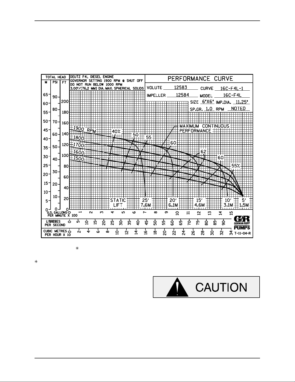
OUTLINE DRAWING
specific application. Since the pressure supplied
to the pump is critical to performance and safety,
be sure to limit the incoming pressure to 50% of
the maximum permissible operating pressure as
shown on the pump performance curve. (See Sec
tion E, Page 1.)
For further assistance, contact your Gorman‐Rupp
distributor or the Gorman‐Rupp Company.
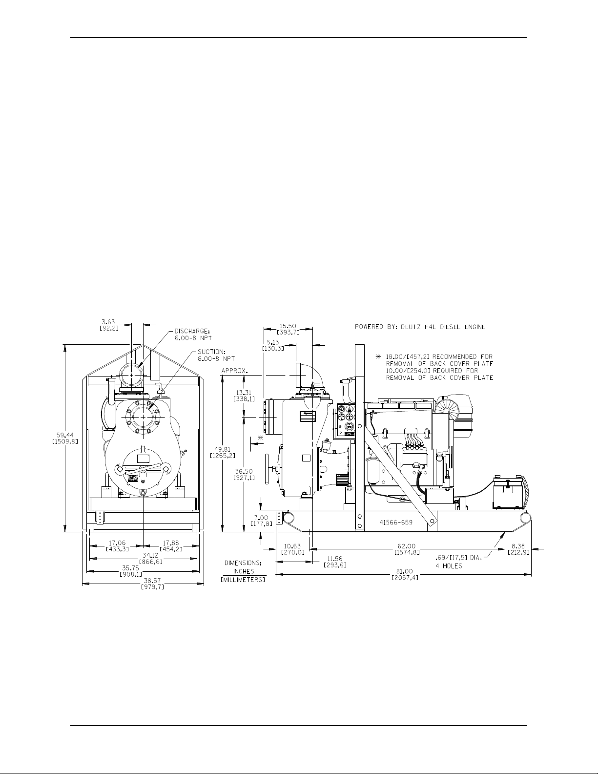
Pump Dimensions
See Figure 1 for the approximate physical dimen
sions of this pump.
Figure 1. Pump Model 16C20‐F4L
PAGE B - 1INSTALLATION
Page 9
OM-01604 10 SERIES
PREINSTALLATION INSPECTION
The pump assembly was inspected and tested be
fore shipment from the factory. Before installation,
inspect the pump for damage which may have oc
curred during shipment. Check as follows:
a. Inspect the pump for cracks, dents, damaged
threads, and other obvious damage.
b. Check for and tighten loose attaching hard
ware. Since gaskets tend to shrink after dry
ing, check for loose hardware at mating sur
faces.
c. Carefully read all warnings and cautions con
tained in this manual or affixed to the pump,
and perform all duties indicated.
d. Check levels and lubricate as necessary. Re
fer to LUBRICATION in the MAINTENANCE
AND REPAIR section of this manual and per
form duties as instructed.
e. If the pump has been stored for more than 12
months, some of the components or lubri
cants may have exceeded their maximum
shelf life. These must be inspected or re
placed to ensure maximum pump service.
If the maximum shelf life has been exceeded, or if
anything appears to be abnormal, contact your
Gorman‐Rupp distributor or the factory to deter
mine the repair or updating policy. Do not put the
pump into service until appropriate action has
been taken.
Before installing the battery, clean the positive and
negative cable connectors, and the battery termi
nals. Secure the battery by tightening the
holddown brackets. The terminals and clamps
may be coated with petroleum jelly to retard corro
sion. Connect and tighten the positive cable first,
then the negative cable.
POSITIONING PUMP
Use lifting and moving equipment in
good repair and with adequate capacity
to prevent injuries to personnel or dam
age to equipment. Suction and dis
charge hoses and piping must be re
moved from the pump before lifting.
Lifting
Pump unit weights will vary depending on the
mounting and drive provided. Check the shipping
tag on the unit packaging for the actual weight, and
use lifting equipment with appropriate capacity.
Drain the pump and remove all customer‐installed
equipment such as suction and discharge hoses
or piping before attempting to lift existing, installed
units.
Battery Specifications And Installation
Unless otherwise specified on the pump order, the
engine battery was not included with the unit. Re
fer to the following specifications when selecting a
battery.
Table 1. Battery Specifications
Cold Reserve Approx.
Crank Capacity Amp/ Overall
Voltage
12 Volts 960‐975 365 175 8.75W
Refer to the information accompanying the battery
and/or electrolyte solution for activation and charg
ing instructions.
PAGE B - 2 INSTALLATION
Amps @80°F Hr. Dims.
@ 0°F (Minutes) Rating (Inches)
20.5L
x
x
9.75H
The pump assembly can be seriously
damaged if the cables or chains used to lift
and move the unit are improperly wrapped
around the pump.
Mounting
Locate the pump in an accessible place as close as
practical to the liquid being pumped. Level mount
ing is essential for proper operation.
The pump may have to be supported or shimmed
to provide for level operation or to eliminate vibra
tion.
If the pump has been mounted on a movable base,
make certain the base is stationary by setting the
Page 10

OM-0160410 SERIES
brake and blocking the wheels before attempting
to operate the pump.
To ensure sufficient lubrication and fuel supply to
the engine, do not position the pump and engine
more than 15
tion. The pump and engine may be positioned up
to 30_ off horizontal for intermittent operation
only; however, the engine manufacturer should be
consulted for continuous operation at angles
greater than 15_.
Clearance
When positioning the pump, allow a minimum
clearance of 18 inches (457 mm) in front of the
back cover to permit removal of the cover and easy
access to the pump interior.
_
off horizontal for continuous opera
SUCTION AND DISCHARGE PIPING
Pump performance is adversely effected by in
creased suction lift, discharge elevation, and fric
tion losses. Contact the factory to be sure your
overall application allows the pump to operate
within the safe operation range.
Materials
Lines near the pump must be independently sup
ported to avoid strain on the pump which could
cause excessive vibration, decreased bearing life,
and increased shaft and seal wear. If hose‐type
lines are used, they should have adequate support
to secure them when filled with liquid and under
pressure.
Gauges
Most pumps are drilled and tapped for installing
discharge pressure and vacuum suction gauges. If
these gauges are desired for pumps that are not
tapped, drill and tap the suction and discharge
lines not less than 18 inches (457,2 mm) from the
suction and discharge ports and install the lines.
Installation closer to the pump may result in erratic
readings.
SUCTION LINES
To avoid air pockets which could affect pump prim
ing, the suction line must be as short and direct as
possible. When operation involves a suction lift, the
line must always slope upward to the pump from
the source of the liquid being pumped; if the line
slopes down to the pump at any point along the
suction run, air pockets will be created.
Either pipe or hose maybe used for suction and
discharge lines; however, the materials must be
compatible with the liquid being pumped. If hose is
used in suction lines, it must be the rigid‐wall, rein
forced type to prevent collapse under suction. Us
ing piping couplings in suction lines is not recom
mended.
Line Configuration
Keep suction and discharge lines as straight as
possible to minimize friction losses. Make mini
mum use of elbows and fittings, which substan
tially increase friction loss. If elbows are necessary,
use the long‐radius type to minimize friction loss.
Connections to Pump
Before tightening a connecting flange, align it ex
actly with the pump port. Never pull a pipe line into
place by tightening the flange bolts and/or cou
plings.
Fittings
Suction lines should be the same size as the pump
inlet. If reducers are used in suction lines, they
should be the eccentric type, and should be in
stalled with the flat part of the reducers uppermost
to avoid creating air pockets. Valves are not nor
mally used in suction lines, but if a valve is used,
install it with the stem horizontal to avoid air pock
ets.
Strainers
If a strainer is furnished with the pump, be certain
to use it; any spherical solids which pass through a
strainer furnished with the pump will also pass
through the pump itself.
If a strainer is not furnished with the pump, but is
installed by the pump user, make certain that the
total area of the openings in the strainer is at least
three or four times the cross section of the suction
line, and that the openings will not permit passage
PAGE B - 3INSTALLATION
Page 11

OM-01604 10 SERIES
of solids larger than the solids handling capability
of the pump.
This pump is designed to handle up to 3 inch (76,2
mm) diameter spherical solids.
Sealing
Since even a slight leak will affect priming, head,
and capacity, especially when operating with a
high suction lift, all connections in the suction line
should be sealed with pipe dope to ensure an air
tight seal. Follow the sealant manufacturer's rec
ommendations when selecting and applying the
pipe dope. The pipe dope should be compatible
with the liquid being pumped.
Suction Lines In Sumps
If a single suction line is installed in a sump, it
should be positioned away from the wall of the
sump at a distance equal to 1 1/2 times the diame
ter of the suction line.
If there is a liquid flow from an open pipe into the
sump, the flow should be kept away from the suc
tion inlet because the inflow will carry air down into
the sump, and air entering the suction line will re
duce pump efficiency.
If it is necessary to position inflow close to the suc
tion inlet, install a baffle between the inflow and the
suction inlet at a distance 1 1/2 times the diameter
of the suction pipe. The baffle will allow entrained
air to escape from the liquid before it is drawn into
the suction inlet.
If two suction lines are installed in a single sump,
the flow paths may interact, reducing the efficiency
of one or both pumps. To avoid this, position the
suction inlets so that they are separated by a dis
tance equal to at least 3 times the diameter of the
suction pipe.
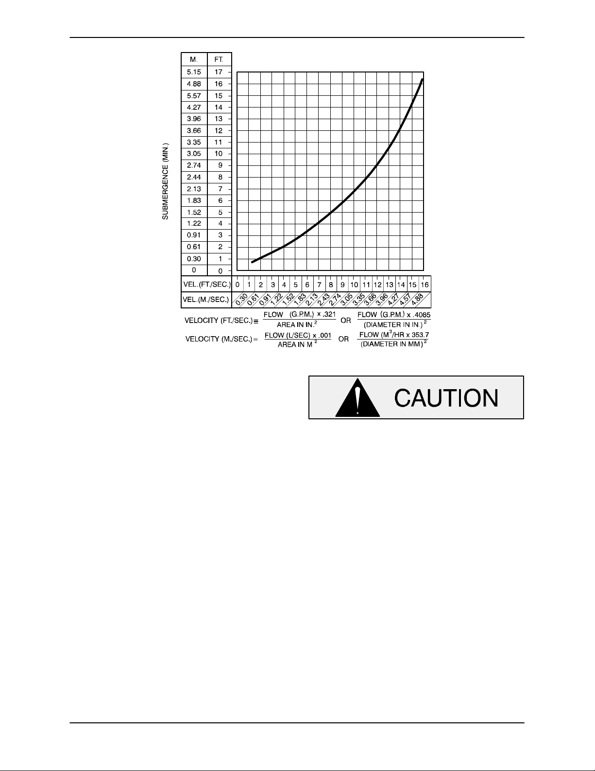
Suction Line Positioning
The depth of submergence of the suction line is
critical to efficient pump operation.
recommended minimum submergence vs. veloc
ity.
Figure 2 shows
NOTE
The pipe submergence required may be reduced
by installing a standard pipe increaser fitting at the
end of the suction line. The larger opening size will
reduce the inlet velocity. Calculate the required
submergence using the following formula based
on the increased opening size (area or diameter).
PAGE B - 4 INSTALLATION
Page 12
OM-0160410 SERIES
Figure 2. Recommended Minimum Suction Line Submergence vs. Velocity
DISCHARGE LINES
Siphoning
Do not terminate the discharge line at a level lower
than that of the liquid being pumped unless a si
phon breaker is used in the line. Otherwise, a si
phoning action causing damage to the pump
could result.
Valves
If a throttling valve is desired in the discharge line,
use a valve as large as the largest pipe to minimize
friction losses. Never install a throttling valve in a
suction line.
With high discharge heads, it is recommended that
a throttling valve and a system check valve be in
stalled in the discharge line to protect the pump
from excessive shock pressure and reverse rota
tion when it is stopped.
If the application involves a high discharge
head, gradually close the discharge
throttling valve before stopping the pump.
Bypass Lines
Self‐priming pumps are not air compressors. Dur
ing the priming cycle, air from the suction line must
be vented to atmosphere on the discharge side. If
the discharge line is open, this air will be vented
through the discharge. However, if a check valve
has been installed in the discharge line, the dis
charge side of the pump must be opened to atmos
pheric pressure through a bypass line installed be
tween the pump discharge and the check valve. A
self‐priming centrifugal pump will not prime if
there is sufficient static liquid head to hold the dis
charge check valve closed.
NOTE
The bypass line should be sized so that it does not
affect pump discharge capacity; however, the by
pass line should be at least 1 inch (25,4 mm) in di
PAGE B - 5INSTALLATION
Page 13

OM-01604 10 SERIES
ameter to minimize the chance of plugging.
In low discharge head applications (less than 30
feet (9,1 m)), it is recommended that the bypass
line be run back to the wet well, and located 6
inches below the water level or cut‐off point of the
low level pump. In some installations, this bypass
outline may be terminated with a six‐to‐eight foot
(1,8 to 2,4 m) length of 1‐1/4 inch (31,8 mm) I.D.
smooth‐bore hose; air and liquid vented during
the priming process will then agitate the hose and
break up any solids, grease, or other substances
likely to cause clogging.
A bypass line that is returned to a wet well
must be secured against being drawn into
the pump suction inlet.
It is also recommended that pipe unions be in
stalled at each 90_ elbow in a bypass line to ease
disassembly and maintenance.
In high discharge head applications (more than
30 feet (9,1 m), an excessive amount of liquid may
be bypassed and forced back to the wet well under
the full working pressure of the pump; this will re
duce overall pumping efficiency. Therefore, it is
recommended that a Gorman‐Rupp Automatic
Air Release Valve be installed in the bypass line.
Gorman‐Rupp Automatic Air Release Valves are
reliable, and require minimum maintenance. See
Automatic Air Release Valves in this section for
installation and theory of operation of the Auto
matic Air Release Valve. Consult your Gorman‐
Rupp distributor, or contact the Gorman‐Rupp
Company for selection of an Automatic Air Release
Valve to fit your application.
be a full‐opening, ball‐type valve to pre
vent plugging by solids.
A manual shut‐off valve should not be
installed in any bypass line. A manual
shut‐off valve may inadvertently be left
closed during operation. A pump which
has lost prime may continue to operate
without reaching prime, causing dan
gerous overheating and possible explo
sive rupture of the pump casing. Per
sonnel could be severely injured.
Allow an over‐heated pump to com
pletely cool before servicing. Do not re
move plates, covers, gauges, or fittings
from an over‐heated pump. Liquid with
in the pump can reach boiling tempera
tures, and vapor pressure within the
pump can cause parts being disen
gaged to be ejected with great force. Af
ter the pump completely cools, drain the
liquid from the pump by removing the
casing drain plug. Use caution when re
moving the plug to prevent injury to per
sonnel from hot liquid.
AUTOMATIC AIR RELEASE VALVE
When properly installed and correctly adjusted to
the specific hydraulic operating conditions of the
application, the Gorman‐Rupp Automatic Air Re
lease Valve will permit air to escape through the by
pass line, and then close automatically when the
pump is fully primed and pumping at full capacity.
Theory of Operation
Except in certain specific applications (to
prevent flooding during service of an auto
matic air release valve in a below‐ground
lift station), if a manual shut‐off valve is in
stalled anywhere in a bypass line, it must
PAGE B - 6 INSTALLATION
Figure 4. Valve in Open Position
Page 14

OM-0160410 SERIES
Figures 4 and 5 show a cross‐sectional view of the
Automatic Air Release Valve, and a corresponding
description of operation.
During the priming cycle, air from the pump casing
flows through the bypass line, and passes through
the Air Release Valve to the wet well (Figure 4).
Figure 5. Valve in Closed Position
When the pump is fully primed, pressure resulting
from flow against the valve diaphragm com
presses the spring and closes the valve (Figure 5).
The valve will remain closed, reducing the bypass
of liquid to 1 to 5 gallons (3,8 to 18,9 L) per minute,
until the pump loses its prime or stops.
When the pump shuts down, the spring returns the
diaphragm to its original position. Any solids that
may have accumulated in the diaphragm chamber
settle to the bottom and are flushed out during the
next priming cycle.
NOTE
The valve will remain open if the pump does not
reach its designed capacity or head. Valve closing
pressure is dependent upon the discharge head of
the pump at full capacity. The range of the valve
closing pressure is established by the tension rate
of the spring as ordered from the factory. Valve clos
ing pressure can be further adjusted to the exact
system requirements by moving the spring retain
ing pin up or down the plunger rod to increase or
decrease tension on the spring. Contact your Gor
man‐Rupp distributor or the Gorman‐Rupp Compa
ny for information about an Automatic Air Release
Valve for your specific application.
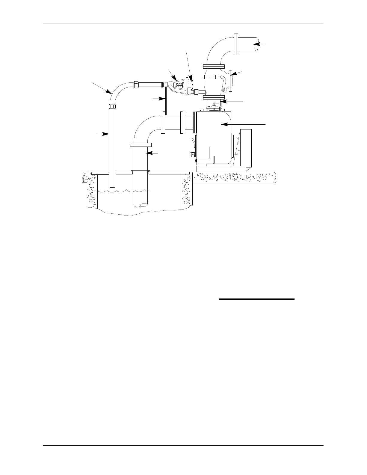
Air Release Valve Installation
The Automatic Air Release Valve must be inde
pendently mounted in a horizontal position and
connected to the discharge line of the self‐priming
centrifugal pump (see Figure 6).
Some leakage (1 to 5 gallons (3,8 to 18,9
Liters) per minute) will occur when the
valve is fully closed. Be sure the bypass
line is directed back to the wet well or
tank to prevent hazardous spills.
NOTE
If the Air Release Valve is to be installed on a staged
pump application, contact the factory for specific
installation instructions.
PAGE B - 7INSTALLATION
Page 15
OM-01604 10 SERIES
INSTALL AIR RELEASE VALVE
IN HORIZONTAL POSITION
90_ LONG
RADIUS
ELBOW
BLEED LINE 1”
(25,4 MM) DIA. MIN.
(CUSTOMER FUR
NISHED) DO NOT EX
TEND BELOW PUMP
OFF LIQUID LEVEL
SUPPORT
BRACKET
CLEAN‐OUT
COVER
SUCTION
LINE
WET WELL
OR SUMP
DISCHARGE PIPE
DISCHARGE
CHECK VALVE
PUMP DISCHARGE
SELF‐PRIMING
CENTRIFUGAL
PUMP
Figure 6. Typical Automatic Air Release Valve Installation
The valve inlet line must be installed between the
pump discharge port and the non‐pressurized side
of the discharge check valve. The valve inlet is at
the large end of the valve body, and is provided
with standard 1 inch NPT pipe threads.
The valve outlet is located at the opposite end of
the valve, and is also equipped with standard 1
inch NPT pipe threads. The outlet should be con
nected to a bleed line which slopes back to the wet
well or sump. The bleed line must be the same size
as the inlet piping, or larger. If piping is used for the
bleed line, avoid the use of elbows whenever pos
sible.
NOTE
It is recommended that each Air Release Valve be
fitted with an independent bleeder line directed
back to the wet well. However, if multiple Air Re
lease Valves are installed in a system, the bleeder
lines may be directed to a common manifold pipe.
Contact your Gorman‐Rupp distributor or the Gor
man‐Rupp Company for information about installa
tion of an Automatic Air Release Valve for your spe
cific application.
ALIGNMENT
The alignment of the pump and the engine is criti
cal for trouble‐free mechanical operation. See Sec
tion E, Securing Intermediate And Drive Assem
bly To Engine for detailed information.
PAGE B - 8 INSTALLATION
Page 16
10 SERIES
OM-01604
OPERATION - SECTION C
Review all SAFETY information in Section A.
Follow the instructions on all tags, labels and
decals attached to the pump.
Do not operate an internal combustion
engine in an explosive atmosphere.
When operating internal combustion
engines in an enclosed area, make cer
tain that exhaust fumes are piped to the
outside. These fumes contain carbon
monoxide, a deadly gas that is color
less, tasteless, and odorless.
This pump is designed to handle dirty
water containing specified entrained
solids. Do not attempt to pump volatile,
corrosive, or flammable materials, or
any liquids which may damage the
pump or endanger personnel as a result
of pump failure.
Never tamper with the governor to gain
more power. The governor establishes
safe operating limits that should not be
exceeded. The maximum continuous
operating speed for this pump is 2200
RPM.
PRIMING
Install the pump and piping as described in IN
STALLATION. Make sure that the piping connec
tions are tight, and that the pump is securely
mounted. Check that the pump is properly lubri
cated (see LUBRICATION in MAINTENANCE
AND REPAIR).
This pump is self‐priming, but the pump should
never be operated unless there is liquid in the
pump casing.
Never operate this pump unless there is
liquid in the pump casing. The pump will
not prime when dry. Extended operation of
a dry pump will destroy the seal assembly.
Add liquid to the pump casing when:
1. The pump is being put into service for the
first time.
2. The pump has not been used for a consider
able length of time.
3. The liquid in the pump casing has evapo
rated.
Once the pump casing has been filled, the pump
will prime and reprime as necessary.
After filling the pump casing, reinstall
and tighten the fill plug. Do not attempt
to operate the pump unless all connect
ing piping is securely installed. Other
wise, liquid in the pump forced out un
der pressure could cause injury to per
sonnel.
To fill the pump, remove the pump casing fill cover
or fill plug in the top of the casing, and add clean
liquid until the casing is filled. Replace the fill cover
or fill plug before operating the pump.
NOTE
This pump is self‐priming; however, it is not suited
for unattended reprime applications. In the event of
suction check valve failure and loss of prime, the
pump casing must be refilled through the fill cover
or fill plug.
When installed in a flooded suction application,
simply open the system valves and permit the in
coming liquid to evacuate the air. After the pump
OPERATION PAGE C - 1
Page 17
OM-01604 10 SERIES
and piping system have completely filled, evacu
ate any remaining air pockets in the pump or suc
tion line by loosening a pipe plug or opening
bleeder valves.
STARTING
If the pump is equipped with the option
al automatic starting system, it is sub
ject to automatic restart. Keep hands
and clothing away from the unit to pre
vent injury during automatic operation.
Disconnect the positive battery cable
before performing any maintenance.
Failure to do so may result in serious
personal injury.
Consult the operations manual furnished with the
engine.
Starting
line. Air from the suction line will be discharged
through the bypass line back to the wet well during
the priming cycle. When the pump is fully primed
and liquid is flowing steadily from the bypass line,
open the discharge throttling valve. Liquid will then
continue to circulate through the bypass line while
the pump is in operation.
Lines Without a Bypass
Open all valves in the discharge line and start the
engine. Priming is indicated by a positive reading
on the discharge pressure gauge or by a quieter
operation. The pump may not prime immediately
because the suction line must first fill with liquid. If
the pump fails to prime within five minutes, stop it
and check the suction line for leaks.
After the pump has been primed, partially close the
discharge line throttling valve in order to fill the line
slowly and guard against excessive shock pres
sure which could damage pipe ends, gaskets,
sprinkler heads, and any other fixtures connected
to the line. When the discharge line is completely
filled, adjust the throttling valve to the required flow
rate.
On initial start‐up, set the engine speed at the half‐
throttle position. Turn the keyswitch on the control
box to the “START” position until the engine starts.
Release the key and the switch will return to the
“RUN” position.
After the engine starts and the unit is fully primed,
adjust the engine RPM until the desired flow rate is
achieved.
Pump speed and operating condition
points must be within the continuous per
formance range shown on the curve on
page E‐1.
OPERATION
Lines With a Bypass
Leakage
No leakage should be visible at pump mating sur
faces, or at pump connections or fittings. Keep all
line connections and fittings tight to maintain maxi
mum pump efficiency.
Liquid Temperature And Overheating
The maximum liquid temperature for this pump is
160_F (71_C). Do not apply it at a higher operating
temperature.
Overheating can occur if operated with the valves
in the suction or discharge lines closed. Operating
against closed valves could bring the liquid to a
boil, build pressure, and cause the pump to rup
ture or explode. If overheating occurs, stop the
pump and allow it to cool before servicing it. Refill
the pump casing with cool liquid.
Close the discharge throttling valve (if so
equipped) so that the pump will not have to prime
against the weight of the liquid in the discharge
Do not remove plates, covers, gauges,
OPERATIONPAGE C - 2
Page 18
10 SERIES
OM-01604
pipe plugs, or fittings from an over
heated pump. Vapor pressure within the
pump can cause parts being disen
gaged to be ejected with great force. Al
low the pump to completely cool before
servicing.
Strainer Check
If a suction strainer has been shipped with the
pump or installed by the user, check the strainer
regularly, and clean it as necessary. The strainer
should also be checked if pump flow rate begins to
drop. If a vacuum suction gauge has been in
stalled, monitor and record the readings regularly
to detect strainer blockage.
Never introduce air or steam pressure into the
pump casing or piping to remove a blockage. This
could result in personal injury or damage to the
equipment. If backflushing is absolutely neces
sary, liquid pressure must be limited to 50% of the
maximum permissible operating pressure shown
on the pump performance curve. (See Section E,
Page 1.)
Pump Vacuum Check
With the pump inoperative, install a vacuum gauge
in the system, using pipe dope on the threads.
Block the suction line and start the pump. At oper
ating speed the pump should pull a vacuum of 20
inches (508,0 mm) or more of mercury. If it does
not, check for air leaks in the seal, gasket, or dis
charge valve.
Open the suction line, and read the vacuum gauge
with the pump primed and at operation speed.
Shut off the pump. The vacuum gauge reading will
immediately drop proportionate to static suction
lift, and should then stabilize. If the vacuum reading
falls off rapidly after stabilization, an air leak exists.
Before checking for the source of the leak, check
the point of installation of the vacuum gauge.
STOPPING
Stopping
Reduce the throttle speed slowly, and allow the en
gine to idle briefly before switching the HAND‐OFF‐
AUTO switch to `OFF'.
If the application involves a high discharge
head, gradually close the discharge
throttling valve before stopping the pump.
After stopping the pump, close and lock the control
panel cover, or disconnect the positive battery
cable to ensure that the pump will remain inopera
tive.
Safety Shutdown System
The unit is equipped with a safety system to auto
matically shut down the engine under certain con
ditions. The engine will automatically shut down:
1. If the engine exceeds its safe operating tem
perature.
2. If the engine oil pressure drops below design
limits.
3. If the engine fails to start within a pre‐set peri
od of time.
4. If the engine speed exceeds the safe operat
ing range.
5. If the engine fan belt breaks.
Lights on the control panel will indicate which of the
safety features has caused the engine to shut
down.
Should any of the safety features cause the engine
to shut down, the cause must be determined and
corrected before putting the unit back into service.
The engine will not restart until the HAND‐OFF‐
AUTO switch has been returned to the `OFF' posi
tion for at least 10 seconds.
All safety shutdown features are pre‐set at the fac
tory for optimum performance and safety; do not
attempt to adjust these settings.
Never halt the flow of liquid suddenly. If the liquid
being pumped is stopped abruptly, damaging
shock waves can be transmitted to the pump and
piping system. Close all connecting valves slowly.
OPERATION PAGE C - 3
Never disconnect any of the safety shut
Page 19

OM-01604 10 SERIES
down features; this will void the warran
ty and could result in serious damage to
the unit and/or injury to personnel. Safe
ty shutdown features are pre‐set at the
factory; do not attempt to adjust any of
the settings. Determine the cause of
shutdown before putting the unit back
into service. Consult the factory for ad
ditional information.
OPERATION IN EXTREME HEAT
The safety shutdown system will automatically
stop the unit if engine operating temperature ex
ceeds design limits. If engine over‐temperature
shutdown occurs, allow the unit to cool before re
starting.
If engine overheating continues, check the engine
lubricant level and viscosity. Consult the engine
operation manual for the recommended lubricant
for operation in extreme heat.
If the unit is equipped with the optional auto‐start
control, the float(s) may need to be adjusted to al
low shorter run and longer cooling periods, if pos
sible.
If the pump is equipped with the option
al automatic starting system, it is sub
ject to automatic restart. Keep hands
and clothing away from the unit to pre
vent injury during automatic operation.
Disconnect the battery before perform
ing any maintenance. Failure to do so
may result in serious personal injury.
BEARING TEMPERATURE CHECK
Bearings normally run at higher than ambient tem
peratures because of heat generated by friction.
Temperatures up to 160_F (71_C) are considered
normal for bearings, and they can operate safely to
at least 180_F (82_C).
Checking bearing temperatures by hand is inaccu
rate. Bearing temperatures can be measured ac
curately by placing a contact‐type thermometer
against the housing. Record this temperature for
future reference.
A sudden increase in bearing temperatures is a
warning that the bearings are at the point of failing
to operate properly. Make certain that the bearing
lubricant is of the proper viscosity and at the cor
rect level (see LUBRICATION in Section E). Bear
ing overheating can also be caused by shaft
misalignment and/or excessive vibration.
When pumps are first started, the bearings may
seem to run at temperatures above normal. Con
tinued operation should bring the temperatures
down to normal levels.
Cold Weather Preservation
In below freezing conditions, drain the pump to
prevent damage from freezing. Also, clean out any
solids by flushing with a hose. Operate the pump
for approximately one minute; this will remove any
remaining liquid that could freeze the pump rotat
ing parts. If the pump will be idle for more than a
few hours, or if it has been pumping liquids con
taining a large amount of solids, drain the pump,
and flush it thoroughly with clean water. To prevent
large solids from clogging the drain port and pre
venting the pump from completely draining, insert
a rod or stiff wire in the drain port, and agitate the
liquid during the draining process. Clean out any
remaining solids by flushing with a hose.
OPERATIONPAGE C - 4
Page 20

TROUBLESHOOTING - SECTION D
Review all SAFETY information in Section A.
Before attempting to open or service the
pump:
1. Familiarize yourself with this man
ual.
2. Switch off engine ignition and dis
connect the positive battery cable
to ensure that the pump will re
main inoperative.
3. Allow the pump to completely cool
if overheated.
4. Check the temperature before
opening any covers, plates, or
plugs.
5. Close the suction and discharge
valves.
6. Vent the pump slowly and cau
tiously.
7. Drain the pump.
OM-0160410 SERIES
TROUBLE POSSIBLE CAUSE PROBABLE REMEDY
PUMP FAILS TO PRIME
PUMP STOPS OR FAILS
TO DELIVER RATED
FLOW OR PRESSURE
Not enough liquid in casing.
Suction check valve contaminated or
damaged.
Air leak in suction line.
Lining of suction hose collapsed.
Leaking or worn seal or pump gasket.
Suction lift or discharge head too high.
Strainer clogged.
Air leak in suction line.
Lining of suction hose collapsed.
Leaking or worn seal or pump gasket.
Strainer clogged.
Add liquid to casing. See PRIMING.
Clean or replace check valve.
Correct leak.
Replace suction hose.
Check pump vacuum. Replace leaking
or worn seal or gasket.
Check piping installation and install by
pass line if needed. See INSTALLA
TION.
Check strainer and clean if necessary.
Correct leak.
Replace suction hose.
Check pump vacuum. Replace leak
ing or worn seal or gasket.
Check strainer and clean if neces
sary.
TROUBLESHOOTING PAGE D - 1
Page 21

OM-01604 10 SERIES
TROUBLE POSSIBLE CAUSE PROBABLE REMEDY
PUMP STOPS OR FAILS
TO DELIVER RATED
FLOW OR PRESSURE
(cont.)
Suction intake not submerged at
proper level or sump too small.
Impeller or other wearing parts worn
or damaged.
Check installation and correct sub
mergence as needed.
Replace worn or damaged parts.
Check that impeller is properly cen
tered and rotates freely.
PUMP REQUIRES TOO
MUCH POWER
PUMP CLOGS
FREQUENTLY
Impeller clogged.
Discharge head too high.
Suction lift too high.
Pump speed too slow.
Pump speed too high.
Discharge head too low.
Liquid solution too thick.
Bearing(s) frozen.
Discharge flow too slow.
Liquid solution too thick.
Discharge line clogged or re
stricted; hose kinked.
Free impeller of debris.
Install bypass line.
Measure lift w/vacuum gauge. Re
duce lift and/or friction losses in suc
tion line.
Check engine output; consult engine
operation manual.
Check engine output.
Adjust discharge valve.
Dilute if possible.
Disassemble pump and check
bearing(s).
Open discharge valve fully to in
crease flow rate, and run engine at
maximum governed speed.
Dilute if possible.
Check discharge lines; straighten
hose.
Suction check valve or foot valve
clogged or binding.
EXCESSIVE NOISE Cavitation in pump.
Pumping entrained air.
Pump or drive not securely
mounted.
Impeller clogged or damaged.
BEARINGS RUN TOO
HOT
Bearing temperature is high, but
within limits.
Low or incorrect lubricant.
Suction and discharge lines not
properly supported.
Drive misaligned.
Clean valve.
Reduce suction lift and/or friction
losses in suction line. Record vacu
um and pressure gauge readings
and consult local representative or
factory.
Locate and eliminate source of air
bubble.
Secure mounting hardware.
Clean out debris; replace damaged
parts.
Check bearing temperature regular
ly to monitor any increase.
Check for proper type and level of
lubricant.
Check piping installation for proper
support.
Align drive properly.
TROUBLESHOOTINGPAGE D - 2
Page 22
OM-0160410 SERIES
PREVENTIVE MAINTENANCE
Since pump applications are seldom identical, and
pump wear is directly affected by such things as
the abrasive qualities, pressure and temperature
of the liquid being pumped, this section is intended
only to provide general recommendations and
practices for preventive maintenance. Regardless
of the application however, following a routine pre
ventive maintenance schedule will help assure
trouble‐free performance and long life from your
Gorman‐Rupp pump. For specific questions con
cerning your application, contact your Gorman‐
Rupp distributor or the Gorman‐Rupp Company.
Record keeping is an essential component of a
good preventive maintenance program. Changes
in suction and discharge gauge readings (if so
equipped) between regularly scheduled inspec
tions can indicate problems that can be corrected
before system damage or catastrophic failure oc
curs. The appearance of wearing parts should also
be documented at each inspection for comparison
as well. Also, if records indicate that a certain part
(such as the seal) fails at approximately the same
duty cycle, the part can be checked and replaced
before failure occurs, reducing unscheduled down
time.
For new applications, a first inspection of wearing
parts at 250 hours will give insight into the wear rate
for your particular application. Subsequent inspec
tions should be performed at the intervals shown
on the chart below. Critical applications should be
inspected more frequently.
Preventive Maintenance Schedule
Service Interval*
Item
General Condition (Temperature, Unusual
Noises or Vibrations, Cracks, Leaks,
Loose Hardware, Etc.) I
Pump Performance (Gauges, Speed, Flow) I
Bearing Lubrication I R
Seal Lubrication (And Packing Adjustment,
If So Equipped) I R
V‐Belts (If So Equipped) I
Air Release Valve Plunger Rod (If So Equipped) I C
Front Impeller Clearance (Wear Plate) I
Rear Impeller Clearance (Seal Plate) I
Check Valve I
Pressure Relief Valve (If So Equipped) C
Pump and Driver Alignment I
Shaft Deflection I
Bearings I
Bearing Housing I
Piping I
Driver Lubrication - See Mfgr's Literature
Daily Weekly Monthly Semi‐
Annually
Annually
Legend:
I = Inspect, Clean, Adjust, Repair or Replace as Necessary
C = Clean
R = Replace
* Service interval based on an intermittent duty cycle equal to approximately 4000 hours annually.
Adjust schedule as required for lower or higher duty cycles or extreme operating conditions.
TROUBLESHOOTING PAGE D - 3
Page 23
10 SERIES
OM-01604
PUMP MAINTENANCE AND REPAIR - SECTION E
MAINTENANCE AND REPAIR OF THE WEARING PARTS OF THE PUMP WILL MAINTAIN PEAK
OPERATING PERFORMANCE.
STANDARD PERFORMANCE FOR PUMP MODEL 16C20‐F4L
Based on 70_F (21_C) clear water at sea level
with minimum suction lift. Since pump installations
are seldom identical, your performance may be dif
ferent due to such factors as viscosity, specific
gravity, elevation, temperature, and impeller trim.
Contact the Gorman‐Rupp Company to verify per
formance or part numbers.
Pump speed and operating condition
If your pump serial number is followed by an “N”,
your pump is NOT a standard production model.
MAINTENANCE & REPAIR PAGE E - 1
points must be within the continuous per
formance range shown on the curve.
Page 24
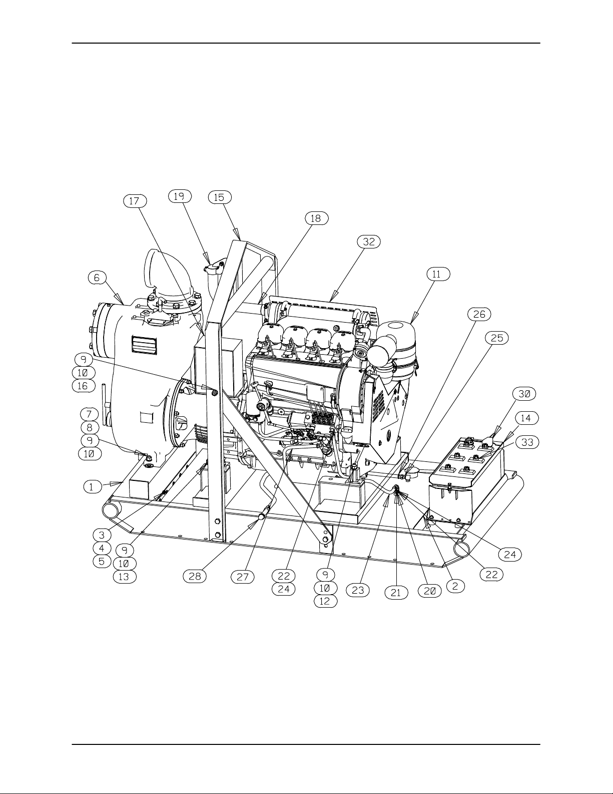
PARTS PAGE
10 SERIESOM-01604
ILLUSTRATION
Figure 1. 16C20‐F4L Pump Assembly
MAINTENANCE & REPAIRPAGE E - 2
Page 25
10 SERIES
OM-01604
PARTS LIST
16C20‐F4L Pump Assembly
(From S/N 1317844 Up)
If your pump serial number is followed by an “N”, your pump is NOT a standard production model. Contact
the Gorman‐Rupp Company to verify part numbers.
ITEM
PART NAME PART
NO.
NUMBER
MAT'L
CODE
QTY ITEM
NO.
PART NAME PART
NUMBER
MAT'L
CODE
QTY
1 COMB BASE 41566-659 24150 1
2 FUEL TANK ASSY 46711-041 --- 1
3 FLAT WASHER K06 15991 10
4 HEX HEAD CAP SCREW B0604 15991 10
5 HEX NUT W/FLANGE 21765-314 --- 10
6 PUMP END ASSY 16C20-(SAE 4/10) 1
7 FLAT WASHER K10 15991 2
8 HEX HEAD CAP SCREW B1009 15991 2
9 LOCK WASHER J10 15991 16
10 HEX NUT D10 15991 16
11 DEUTZ ENGINE 29217-421 --- 1
12 HEX HEAD CAP SCREW B1017 15991 2
13 HEX HEAD CAP SCREW B1007 15991 4
14 BATTERY BOX ASS'Y GRP40-08C --- 1
-HEX HD CAPSCREW B0607 15991 2
-FLAT WASHER KE06 15991 2
-FLANGED HEX NUT 21765-314 --- 2
-GRD CABLE ASSY 47311-064 --- 1
-BATT BOX LID ASSY 42113-012 24150 1
-12V BATTERY SEE OPTIONS REF
-BATTERY TAG 38818-506 --- 1
-BATTERY BOX ASSY 42431-030 24150 1
-STUD MOUNT 24631-006 --- 4
-FLANGED HEX NUT 21765-314 --- 8
-T TYPE LOCKWASHER BL06 15991 1
15 HOIST BAIL ASSY 13351 24000 1
16 HEX HEAD CAPSCREW B1006 15991 8
17 CTRL PNL INSTL KIT 48122-526 --- 1
18 EXHAUST ELBOW 31912-024 15990 1
19 WEATHER CAP S1246 --- 1
20 FUEL RETURN ASSY 14294 24030 1
21 PIPE ELBOW R04 11999 1
22 HOSE BARB FITTING 26523-333 --- 2
23 3/8” ID X 24” LG HOSE 18513-302 --- 1
24 HOSE CLAMP 26518-642 --- 2
25 CONNECTOR S1447 --- 1
26 HOSE ASSY 46341-800 --- 1
27 3/8” ID X 48” LG HOSE 18513-302 --- 1
28 OIL DRAIN ASSEMBLY 46342-007 --- 1
30 POS CABLE ASSEMBLY 47311-114 --- 1
32 MUFFLER GUARD ASSY 42331-033 --- 1
33 12V BATTERY 29331-506 --- 1
NOT SHOWN:
ENG STARTUP TAG 38816-269 --- 1
STRAINER 7823A 24000 1
LOW SULFUR
FUEL DECAL 38816-196 --- 1
OPTIONAL:
12V BATTERY 29331-506 --- 1
WHEEL KIT GRP30-248F--- 1
REP MUFFLER GRD ASSY 42331-048 --- 1
HIGHWAY TRAILERS:
-2” BALL COUPLER 41583-690 --- 1
-3” I.D. PINTLE EYE 41583-700 --- 1
REPAIR CONTROL PANEL
INSTALLATION KIT 48122-527 --- 1
MAINTENANCE & REPAIR PAGE E - 3
Page 26

ILLUSTRATION
10 SERIESOM-01604
Figure 2. 16C20‐(SAE 4/10) Pump End Assembly
MAINTENANCE & REPAIRPAGE E - 4
Page 27

10 SERIES
ITEM
PART NAME PART
NO.
PARTS LIST
16C20‐(SAE 4/10) Pump End Assembly
NUMBER
MAT'L
CODE
QTY ITEM
NO.
PART NAME PART
NUMBER
OM-01604
MAT'L
CODE
QTY
1 PUMP CASING 12583 10010 1
2 IMPELLER 12584 11010 1
3 SEAL ASSEMBLY 12461 --- 1
4 PIPE PLUG P04 15079 1
5 HEX HD CAPSCREW B1208 15991 8
6 LOCKWASHER J12 15991 8
7 PIPE NIPPLE T96 15070 1
8 PIPE ELBOW R96 11990 1
9 DISCHARGE STICKER 6588BJ --- 1
10 DISCHARGE FLANGE 1758 10010 1
11 DISCH FLANGE GSKT 1679G 18000 1
12 NAME PLATE 38818-023 13990 1
13 DRIVE SCREW BM#04-03 17000 4
14 WARNING DECAL 2613FE --- 1
15 STUD C0809 15991 8
16 HEX NUT D08 15991 8
17 AIR VENT S2162 --- 1
18 PIPE COUPLING AE02 15079 1
19 HEAVY PIPE NIPPLE T02 15079 1
20 AIR VENT S1703 --- 1
21 INTERMEDIATE 38263-614 10010 1
22 OIL SEAL S1935 --- 1
23 PIPE PLUG P04 15079 1
24 FILL COVER ASSY 42111-344 --- 1
25 -DRIVE SCREW BM#04-03 17000 2
26 -WARNING PLATE 38816-097 13990 1
27 -COVER PLATE NOT AVAILABLE 1
28 -FILL COVER GSKT 50G 19210 1
29 COVER CLAMP SCREW 31912-009 15000 1
30 MACHINE BOLT A1014 15991 2
31 COVER CLAMP BAR 38111-004 11010 1
32 IMPELLER SHIM SET 5091 17090 REF
33 SHAFT SLEEVE 11907 16000 1
34 BOTTLE OILER S1933 --- 1
35 PIPE ELBOW R02 11999 1
36 PIPE NIPPLE T0220 15079 1
37 PIPE NIPPLE T12 15079 1
38 PIPE COUPLING AE12 15079 1
39 OIL SIGHT GAUGE S1471 --- 1
40 INTERMEDIATE GUARD 42381-031 24152 1
41 INTERMEDIATE GUARD 42381-032 24152 1
42 BRG CAP GSKT 5413G 18000 1
43 HEX HD CAPSCREW B0604 15991 4
44 LOCKWASHER J06 15991 4
45 BEARING CAP 4185A 10010 1
46 SHAFT KEY N0607 15990 1
47 IMPELLER SHAFT 38514-807 1706H 1
48 OIL SEAL 25258-622 --- 1
49 WAVY WASHER 23963-327 --- 1
50 BALL BEARING S1077 --- 1
51 INTERM DRAIN PLUG P06 15079 1
52 BALL BEARING 23421-461 --- 1
53 SEAL CVTY DRAIN PLUG P02 15079 1
54 SEAL PLATE 38272-517 10010 1
55 CASING GSKT SET 34G 18000 1
56 OIL SEAL 25258-622 --- 1
57 WEAR PLATE ASSY 2545 15990 1
58 HEX NUT D08 15991 2
59 LOCKWASHER J08 15991 2
60 CASING DRAIN PLUG P16 10009 1
61 BACK COVER GSKT 7668G 20000 1
62 BACK COVER ASSY 42111-935 --- 1
63 -COVER PLATE NOT AVAILABLE 1
64 -DRAIN PLUG P04 15079 1
65 -DRIVE SCREW BM#04-03 17000 4
66 -WARNING PLATE 2613EV 13990 1
67 COVER CLAMP SCREW 2536 24000 1
68 COVER CLAMP 12586 11010 1
69 MACHINE BOLT A1010 15991 2
70 CHECK VALVE GSKT 11402G 19370 1
71 CHECK VALVE SEAT 11402C 10010 1
72 RD HD MACH SCREW X0506 14990 2
73 SUCT FLANGE GSKT 1679G 18000 1
74 HEX HD CAPSCREW B1214 15991 8
75 LOCKWASHER J12 15991 8
76 SUCTION FLANGE 1758 10010 1
77 SUCTION STICKER 6588AG --- 1
78 PIPE PLUG P04 15079 1
79 CHECK VALVE ASSY 46411-064 --- 1
80 CHECK VALVE PIN 11645 17010 1
81 PRIMING STICKER 6588AH --- 1
NOT SHOWN:
STRAINER 7823A 24000 1
LUBE DECAL 38816-079 --- 1
INSTRUCTION TAG 38817-085 --- 1
DRIVE ASSEMBLY 44162-119 --- 1
INSTRUCTION LABEL 2613DK --- 1
G‐R DECAL GR-03 --- 1
CPB DECAL 29811-055 --- 1
OPTIONAL:
AQ MEEHANITE 12584 1108H 1
INDICATES PARTS RECOMMENDED FOR STOCK
MAINTENANCE & REPAIR PAGE E - 5
Page 28

ILLUSTRATION
10 SERIESOM-01604
Figure 3. 44162-119 Drive Assembly
PARTS LIST
ITEM
NO.
1 COUPLING KIT 48112-001 --- 1
2 -BUSHING 24131-345 --- 1
3 -COUPLING ASSEMBLY 44165-011 --- 1
4 -LOCKWASHER 21171-536 --- 8
5 -SOCKET HD CAPSCREW 22644-220 --- 8
6 HEX HD CAPSCREW 22645-164 --- 12
7 LOCKWASHER 21171-511 --- 12
PART NAME
PART
NUMBER
MAT'L
CODE
MAINTENANCE & REPAIRPAGE E - 6
QTY
Page 29
10 SERIES
OM-01604
PUMP AND SEAL DISASSEMBLY AND REASSEMBLY
Review all SAFETY information in Section A.
Follow the instructions on all tags, label and
decals attached to the pump.
This pump requires little service due to its rugged,
minimum‐maintenance design. However, if it be
comes necessary to inspect or replace the wearing
parts, follow these instructions which are keyed to
the illustrations (see Figures 1 through 3) and the
accompanying parts lists.
This manual will alert personnel to known proce
dures which require special attention, to those
which could damage equipment, and to those
which could be dangerous to personnel. However,
this manual cannot possibly anticipate and provide
detailed precautions for every situation that might
occur during maintenance of the unit. Therefore, it
is the responsibility of the owner/maintenance per
sonnel to ensure that only safe, established main
tenance procedures are used, and that any proce
dures not addressed in this manual are performed
only after establishing that neither personal safety
nor pump integrity are compromised by such prac
tices.
2. Switch off the engine ignition and
disconnect the positive battery
cable to ensure that the pump will
remain inoperative.
3. Allow the pump to completely cool
if overheated.
4. Check the temperature before
opening any covers, plates, or
plugs.
5. Close the suction and discharge
valves.
6. Vent the pump slowly and cau
tiously.
7. Drain the pump.
Use lifting and moving equipment in
good repair and with adequate capacity
to prevent injuries to personnel or dam
age to equipment. Suction and dis
charge hoses and piping must be re
moved from the pump before lifting.
Back Cover Removal
(Figure 2)
Most service functions, such as wear plate, impel
ler, and seal replacement, may be performed by
draining the pump and removing the back cover
assembly. However, the following instructions as
sume complete disassembly is required.
Before attempting to service the pump, switch off
the engine ignition and disconnect the positive bat
tery cable to ensure that the pump will remain inop
erative. Close all valves in the suction and dis
charge lines.
For engine disassembly and repair, consult the lit
erature supplied with the engine, or contact your
local Deutz engine representative.
Before attempting to open or service the
pump:
1. Familiarize yourself with this man
ual.
Before attempting to service the pump, remove the
pump casing drain plug (60) and drain the pump.
Clean and reinstall the drain plug. The wear plate
(57) and check valve (79) are easily accessible and
may be serviced by removing the back cover as
sembly (62).
Remove the cover clamp screw (67) and clamp bar
(68) securing the back cover. Pull the back cover
and assembled wear plate from the pump casing
(1). Inspect the back cover gasket (61) and replace
it if damaged or worn.
Inspect the wear plate and replace it if badly scored
or worn. To remove the wear plate, disengage the
hardware (58 and 59).
Suction Check Valve Removal
(Figure 2)
If the check valve assembly (79) is to be serviced,
reach through the back cover opening and hold
the assembly in place while removing the check
MAINTENANCE & REPAIR PAGE E - 7
Page 30

10 SERIESOM-01604
valve pin (80). Slide the assembly out of the check
valve seat (71) and remove it from the pump.
NOTE
Further disassembly of the check valve is not re
quired since it must be replaced as a complete unit.
Individual parts are not sold separately.
The check valve assembly may also be serviced by
removing the suction flange (76). To remove the
flange, disengage the hardware (74 and 75) and
separate the flange from the check valve seat. Re
move the machine screws (72) and pull the seat
and assembled check valve from the suction port.
Remove the check valve pin and pull the check
valve assembly out of the seat.
Replace the flange gaskets (70 and 73) as re
quired.
Separating Pump and Intermediate from
Engine
As the assemblies separate, the flexible portion of
the coupling assembly (3) will remain on the shaft.
To remove the coupling from the shaft, unscrew the
two allen head setscrews from the bushing (2).
Screw one of the setscrews into the puller hole on
the circumference of the bushing. As the coupling
and bushing separate, remove the bushing, and
slide the coupling off the shaft. Remove the shaft
key (47, Figure 2).
It is not necessary to remove the outer ring of the
coupling from the engine flywheel unless the cou
pling must be replaced. To remove the ring, disen
gage the hardware (4 and 5) securing it to the fly
wheel.
Remove any leveling shims used under the casing
mounting feet. Tie and tag the shims for ease of
reassembly.
Move the pump end to a clean, well equipped shop
area for further disassembly.
Loosening Impeller
(Figure 3)
If the impeller or seal assembly require replace
ment, the pump end and drive assembly must be
separated from the engine.
Support the pump using a suitable hoist and sling.
Remove the hardware (7, 8, 9 and 10, Figure 1) se
curing the pump casing (1) to the base (1, Figure
1).
Use lifting and moving equipment in
good repair and with adequate capacity
to prevent injuries to personnel or dam
age to equipment. Suction and dis
charge hoses and piping must be re
moved from the pump before lifting.
Disengage the hardware (6 and 7) securing the
drive assembly to the intermediate. Separate the
pump end and drive assembly from the engine by
pulling the pump end straight away from the en
gine.
(Figure 2)
Before loosening the impeller (2), drain the seal lu
bricant by removing the seal drain plug (53). This
will prevent the oil from escaping when the impeller
is removed. Clean and reinstall the drain plug.
Reach through the suction port and wedge a block
of wood between the vanes of the impeller and the
pump casing to prevent rotation.
If removed, install the shaft key (46) in the shaft
keyway. Install a lathe dog on the drive end of the
shaft (47) with the “V” notch positioned over the
shaft key.
With the impeller rotation still blocked, see Figure 4
and use a long piece of heavy bar stock to pry
against the arm of the lathe dog in a counterclock
wise direction (when facing the drive end of the
shaft). Use caution not to damage the shaft or key
way. When the impeller breaks loose, remove the
lathe dog, key and wood block.
NOTE
Do not remove the impeller until the rotating assem
bly has been removed from the pump casing.
MAINTENANCE & REPAIRPAGE E - 8
Page 31

10 SERIES
OM-01604
Turn
Counterclockwise
Lathe Dog Arm
“V” Notch
Heavy
Bar Stock
Figure 4. Loosening Impeller
Pump Casing Removal
(Figure 2)
Remove the nuts (16) securing the pump casing to
the seal plate (54). Install a standard 5/8‐11 UNC
lifting eye in the tapped hole in the top of the pump
casing. Be sure to screw the eye into the casing
until fully engaged. Use a hoist and sling of suitable
capacity to separate the casing from the seal plate
and intermediate.
Shaft Key
Impeller Shaft
Lathe Dog
Setscrew
the shaft seal spring will be released as the impeller
is unscrewed. Inspect the impeller and replace if
cracked or badly worn.
Slide the impeller adjusting shims (32) off the im
peller shaft (47). Tie and tag the shims or measure
and record their thickness for ease of reassembly.
Seal Removal and Disassembly
(Figure 2)
To remove the seal assembly (3), remove the bottle
oiler and piping (17, 18 and 19) from the seal plate
(54). Carefully remove the spring holder and
spring. Slide the shaft sleeve (33) and rotating por
tion of the seal assembly off the shaft as a single
unit. Apply oil to the sleeve and work it up under the
rubber bellows. Slide the rotating portion of the
seal off the sleeve.
Carefully slide the seal plate (35) and stationary
portion of the seal off the shaft as a unit. Use a suit
ably sized dowel to press the stationary portion of
the seal out of the seal plate from the back side.
Inspect the oil seal (22) and, if replacement is re
quired, press it from the seal plate.
If no further disassembly is required, refer to Seal
Reassembly And Installation.
Shaft and Bearing Removal and Disassembly
(Figure 2)
Do not attempt to lift the complete pump
unit using the lifting eye. It is designed
to facilitate removal or installation of in
dividual components only. Additional
weight may result in damage to the
When the pump is properly operated and main
tained, the intermediate should not require disas
sembly. Disassemble the shaft and bearings only
when there is evidence of wear or damage.
pump or failure of the eye bolt.
Remove the pump casing gaskets (55). Remove
any leveling shims used under the casing mount
ing feet. Tie and tag the gaskets and shims for ease
of reassembly.
Shaft and bearing disassembly in the field
is not recommended. These operations
should be performed only in a properly‐
Impeller Removal
(Figure 2)
To remove the impeller (2), unscrew it in a counter
clockwise direction (when facing the impeller). Use
caution when removing the impeller; tension on
MAINTENANCE & REPAIR PAGE E - 9
equipped shop by qualified personnel.
Remove the intermediate drain plug (51) and drain
the lubricant. Clean and reinstall the drain plug.
Disengage the hardware (43 and 44) and remove
the bearing cap (45), gasket (42), outboard oil seal
Page 32
10 SERIESOM-01604
(48), and wavy washer (49). Press the oil seal from
the bearing cap.
Place a block of wood against the impeller end of
the shaft (47), and tap the shaft and assembled
bearings (50 and 52) from the intermediate. Press
the inboard oil seal (56) from the intermediate.
After removing the shaft and bearings, clean and
inspect the bearings in place as follows.
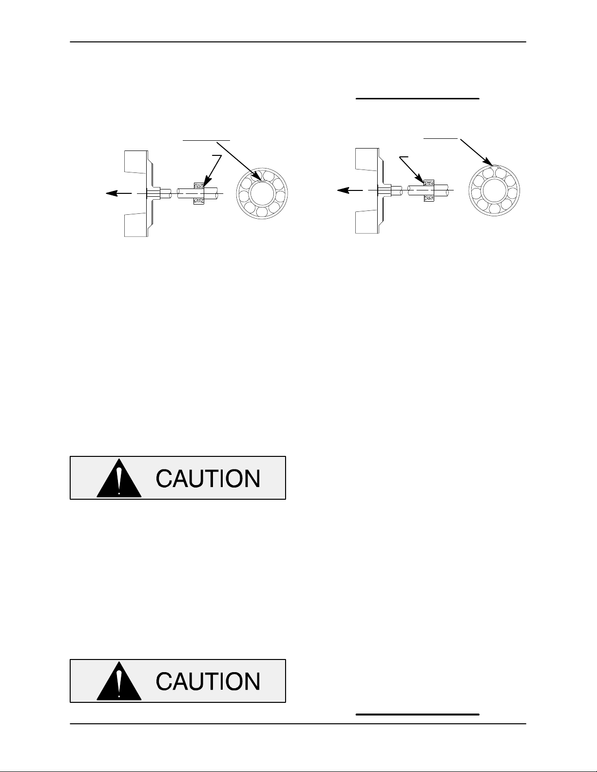
To prevent damage during removal from
the shaft, it is recommended that bearings
be cleaned and inspected in place. It is
strongly recommended that the bearings
be replaced any time the shaft and bear
ings are removed.
Clean the intermediate, shaft and all component
parts (except the bearings) with a soft cloth soaked
in cleaning solvent. Inspect the parts for wear or
damage and replace as necessary.
tation is rough or the bearing balls are discolored,
replace the bearings.
The bearing tolerances provide a tight press fit
onto the shaft and a snug slip fit into the intermedi
ate. Replace the bearings, shaft, or intermediate if
the proper bearing fit is not achieved.
If bearing replacement is required, use a bearing
puller to remove the inboard and outboard bear
ings (18 and 29) from the shaft.
Shaft and Bearing Reassembly and Installation
(Figure 2)
Inspect the shaft for distortion, nicks or scratches,
or for thread damage on the impeller end. Dress
small nicks and burrs with a fine file or emery cloth.
Replace the shaft if defective.
Position the inboard oil seal (56) in the intermediate
housing bore with the lip positioned as shown in
Figure 2. Press the oil seal into the housing until the
face is just flush with the machined surface on the
housing.
Clean and inspect the bearings as indicated in
Shaft And Bearing Removal And Disassembly.
Most cleaning solvents are toxic and
flammable. Use them only in a well ven
tilated area free from excessive heat,
sparks, and flame. Read and follow all
precautions printed on solvent contain
ers.
Clean the bearings thoroughly in fresh cleaning
solvent. Dry the bearings with filtered compressed
air and coat with light oil.
Bearings must be kept free of all dirt and
foreign material. Failure to do so will great
ly shorten bearing life. Do not spin dry
bearings. This may scratch the balls or
races and cause premature bearing fail
ure.
Rotate the bearings by hand to check for rough
ness or binding and inspect the bearing balls. If ro
To prevent damage during removal from
the shaft, it is recommended that bearings
be cleaned and inspected in place. It is
strongly recommended that the bearings
be replaced any time the shaft and bear
ings are removed.
The bearings may be heated to ease installation.
An induction heater, hot oil bath, electric oven, or
hot plate may be used to heat the bearings. Bear
ings should never be heated with a direct flame or
directly on a hot plate.
NOTE
If a hot oil bath is used to heat the bearings, both the
oil and the container must be absolutely clean. If
the oil has been previously used, it must be thor
oughly filtered.
Heat the bearings to a uniform temperature no
higher than 250_F (120_C), and slide the bearings
MAINTENANCE & REPAIRPAGE E - 10
Page 33
10 SERIES
OM-01604
onto the shaft, one at a time, until they are fully
seated. This should be done quickly, in one con
tinuous motion, to prevent the bearings from cool
ing and sticking on the shaft.
BALL LOADING
GROOVE POSITIONED
AWAY FROM IMPELLER
LOADING
GROOVE
DIRECTION OF
THRUST
INSTALLATION OF FEDERAL MOGAL 5300W
OR NTN 3300 SERIES BEARINGS
(OPEN OR ENCLOSED IMPELLERS)
Figure 4. Inboard Bearing Positioning
After the bearings have been installed and allowed
to cool, check to ensure that they have not moved
away from the shaft shoulders in shrinking. If
movement has occurred, use a suitably sized
sleeve and a press to reposition the bearings
against the shaft shoulders.
If heating the bearings is not practical, use a suit
ably sized sleeve, and an arbor (or hydraulic) press
to install the bearings on the shaft.
NOTE
Position the inboard bearing (52) on the shaft as in
dicated in Figure 4.
BALL LOADING
GROOVE POSITIONED
TOWARD IMPELLER
LOADING
GROOVE
DIRECTION OF
THRUST
INSTALLATION OF MRC/SKF 5300M, 5300E OR
TIMKEN 5300W SERIES BEARINGS
(OPEN OR ENCLOSED IMPELLERS)
the bearing bore, push against the outer
race. Never hit the balls or ball cage.
Apply a light coating of oil to the lip of the outboard
oil seal (48), and press it into the bearing cap (45)
with the lip positioned as shown in Figure 2. The
face of the oil seal should be just flush with the
outer face of the bearing cap.
Install the wavy washer (49) and bearing cap gas
ket (42), and secure the bearing cap to the interme
diate with the hardware (43 and 44). Be careful not
to damage the lip of the oil seal (48) on the shaft
keyway.
Lubricate the bearings as indicated in LUBRICA
When installing the bearings onto the
TION at the end of this section.
shaft, never press or hit against the outer
race, balls, or ball cage. Press only on the
inner race.
Slide the shaft (47) and assembled bearings (50
and 52) into the intermediate bore until the inboard
bearing is fully seated against the bore shoulder.
Be careful not to damage the lip of the oil seal (56)
on the shaft threads.
Securing Intermediate And Drive Assembly To
Engine
(Figure 3)
Install the shaft key (46, Figure 2) in the shaft key
way. Position the flexible portion of the coupling as
sembly (3) on the shaft as shown in Figure 3.
NOTE
The flexible portion of the coupling must be proper
ly positioned on the shaft. The heads of the caps
crews in the center of the coupling must be posi
tioned toward the pump end of the shaft.
When installing the shaft and bearings into
MAINTENANCE & REPAIR PAGE E - 11
Page 34
10 SERIESOM-01604
housing with the previously removed hardware (6
and 7).
Make certain that the flexible portion of the
coupling is mounted to the dimension
shown in Figure 3. This dimension is crit
ical. If the coupling is not properly posi
tioned on the shaft, the coupling parts may
not fully engage, or a pre‐load condition
can cause premature bearing failure.
The end of the bushing must be just flush
from the end of the shaft. This will allow the
two portions of the coupling to fully engage
when the intermediate is secured to the en
gine bellhousing, without pre‐loading the
bearings.
With the flexible portion of the coupling and the
bushing properly positioned on the shaft, tighten
the two setscrews in an alternating sequence until
the bushing and coupling are fully secured. Torque
the setscrews to 14.5 ft. lbs. (175 in. lbs. or 2,02 m.
kg.).
Seal Reassembly and Installation
(Figures 2 and 5)
Clean the seal cavity and shaft with a cloth soaked
in fresh cleaning solvent.
Most cleaning solvents are toxic and
flammable. Use them only in a well ven
tilated area free from excessive heat,
sparks, and flame. Read and follow all
precautions printed on solvent contain
ers.
The seal is not normally reused because wear pat
terns on the finished faces cannot be realigned
during reassembly. This could result in premature
failure. If necessary to reuse an old seal in an emer
gency, carefully wash all metallic parts in fresh
cleaning solvent and allow to dry thoroughly.
If the complete coupling assembly is being re
placed, apply `Loctite Retaining Compound No.
242' or equivalent compound to the threads of the
hardware (4 and 5), and secure the outer ring of the
coupling to the engine flywheel by torquing the
hardware to 45 ft. lbs. (540 in. lbs. or 6,2 m. kg.).
Using a suitable lifting device, position the as
sembled coupling, intermediate, shaft and bear
ings so the flexible portion of the coupling seats in
side the outer ring attached to the engine flywheel.
NOTE
To ease installation, lightly lubricate the rubber por
tion of the coupling with a non‐petroleum based
lubricant such as vegetable oil or glycerin, or a sili
con‐based lubricant such as “WD40” or equivalent.
Do not use petroleum‐based lubricants, or any oth
er substance which may soften or otherwise dam
age the rubber.
Install the intermediate guards (40 and 41, Figure
2), and secure the intermediate to the engine bell
Handle the seal parts with extreme care to prevent
damage. Be careful not to contaminate precision
finished faces; even fingerprints on the faces can
shorten seal life. If necessary, clean the faces with a
non‐oil based solvent and a clean, lint‐free tissue.
Wipe lightly in a concentric pattern to avoid
scratching the faces.
Inspect the seal components for wear, scoring,
grooves, and other damage that might cause leak
age. Clean and polish the shaft sleeve, or replace it
if there are nicks or cuts on either end. If any com
ponents are worn, replace the complete seal;
never mix old and new seal parts.
If a replacement seal is being used, remove it from
the container and inspect the precision finished
faces to ensure that they are free of any foreign
matter.
To ease installation of the seal, lubricate the O‐
rings, sleeve, and bellows with water or a very
small amount of oil, and apply a drop of light lubri
cating oil on the finished faces. Assemble the seal
as follows, (see Figure 5).
MAINTENANCE & REPAIRPAGE E - 12
Page 35
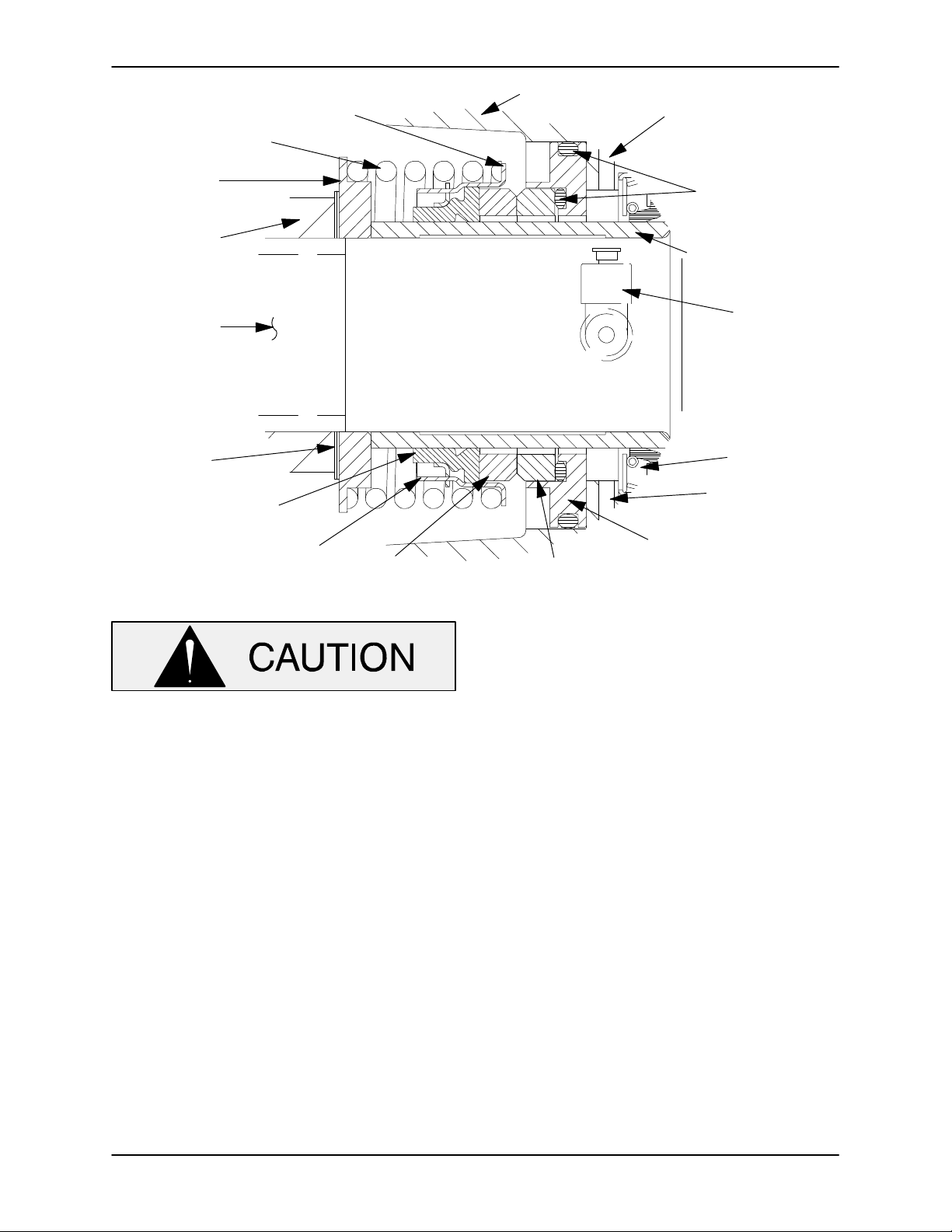
10 SERIES
SPRING
HOLDER
SPRING
RETAINER
OM-01604
SEAL PLATE
AIR VENT
O‐RINGS
IMPELLER
IMPELLER
SHAFT
IMPELLER
SHIMS
BELLOWS
DRIVE BAND
ROTATING ELEMENT
Figure 5. 12461 Seal Assembly
This seal is not designed for operation at
temperatures above 160_F (71_C). Do not
use at higher operating temperatures.
Inspect the seal plate (54) and the impeller shaft
(47) for burrs or sharp corners, and remove any
that exist. Install the oil seal (22) in the bore of the
seal plate as shown in Figure 2. Make sure the oil
seal is fully seated.
Position the seal plate against the intermediate. Be
careful not to damage the oil seal lip on the shaft
threads. Align the bottle oiler hole with the opening
in the intermediate, and temporarily secure the
seal plate to the intermediate with two capscrews
and nuts (1/2 UNC by 1-1/2 inch long, not
supplied).
SHAFT SLEEVE
BOTTLE
OILER
OIL SEAL
DRAIN PLUG
STATIONARY SEAT
STATIONARY ELEMENT
the tube should be approximately the same as the
I.D. of the seal spring.
Subassemble the rotating element into the rotating
portion of the seal assembly with the chamfered
side facing out. Slide the rotating portion of the seal
assembly onto the shaft sleeve (33) with the rotat
ing element facing the chamfered end of the
sleeve. Slide the sleeve onto the shaft until the seal
elements contact and the sleeve bottoms against
the shaft shoulder. Be careful not to roll or damage
the lip of the seal plate oil seal (22).
Install the seal spring and spring holder.
Reinstall the bottle oiler and piping (34, 35 and 36)
and the air vent and piping (17, 18 and 19).
Lubricate the seal as indicated in LUBRICATION,
after the impeller has been installed.
Impeller Installation And Adjustment
Assemble the O‐rings into the stationary seat.
Press the stationary seat into the seal plate bore
until fully seated. A push tube cut from a length of
plastic pipe would aid this installation. The I.D. of
MAINTENANCE & REPAIR PAGE E - 13
(Figure 2)
Inspect the impeller, and replace it if cracked or
badly worn.
Page 36
The shaft and impeller threads must be
completely clean before reinstalling the im
peller. Even the slightest amount of dirt on
the threads can cause the impeller to seize
to the shaft, making future removal difficult
or impossible without damage to the im
peller or shaft.
Install the same thickness of impeller adjusting
shims (32) as previously removed, and screw the
impeller (2) onto the shaft until tight.
NOTE
At the slightest sign of binding, immediately back
the impeller off, and check the threads for dirt. Do
not try to force the impeller onto the shaft.
10 SERIESOM-01604
NOTE
An alternate method of adjusting this clearance is to
reach through the discharge port with a feeler
gauge and measure the gap. Add or subtract pump
casing gaskets accordingly.
If a lifting eye was used to move the pump casing,
be sure to remove the lifting eye from the pump
casing.
Do not attempt to lift the complete pump
unit using the lifting eye. It is designed
to facilitate removal or installation of in
dividual components only. Additional
weight may result in damage to the
pump or failure of the eye bolt.
A clearance of .025 to .040 inch (0,64 to 1,02 mm)
between the impeller and the seal plate is neces
sary for maximum pump efficiency. Measure this
clearance, and add or remove impeller adjusting
shims as required.
Remove the two capscrews temporarily holding
the seal plate, and install the same thickness of
casing gaskets (55) as previously removed. Se
cure the seal plate and pump casing to the inter
mediate with the nuts (16). Do not fully tighten the
nuts until the impeller face clearance has been set.
NOTE
If the pump has been completely disassembled, it
is recommended that the wear plate (57) and back
cover assembly (62) be reinstalled at this point. The
back cover and wear plate must be in place to ad
just the impeller face clearance.
Suction Check Valve Installation
(Figure 2)
Inspect the check valve assembly (79), and re
place it if badly worn.
NOTE
The check valve assembly must be replaced as a
complete unit. Individual parts are not sold sepa
rately.
Replace the seat gasket (70) and secure the check
valve seat (71) to the pump casing with the round
head machine screws (72).
NOTE
If the suction flange or check valve seat was re
moved, replace the respective gaskets, and apply
`Permatex Aviation No. 3 Form‐A‐Gasket' or equiva
lent compound to the mating surfaces.
A clearance of .010 to .020 inch (0,25 to 0,51 mm)
between the impeller and the wear plate is also rec
ommended for maximum pump efficiency. This
clearance must be set after installing the back
cover, by adding or removing gaskets in the pump
casing gasket set (55) until the impeller scrapes
against the wear plate when the shaft is turned. Af
ter the impeller scrapes, add approximately .010
inch (0,25 mm) of gaskets.
Reach through the back cover opening with the as
sembled check valve, and position the check valve
adaptor in the mounting slot in the check valve
seat. Align the adaptor with the seat hole, and se
cure the assembly with the check valve pin (80).
Replace the suction flange gasket (73). Secure the
suction flange (76) to the check valve seat and
pump casing with the hardware (74 and 75).
MAINTENANCE & REPAIRPAGE E - 14
Page 37
10 SERIES
OM-01604
Back Cover Installation
(Figure 2)
If the wear plate (57) was removed for replace
ment, carefully center it on the back cover (63) and
secure it with the hardware (58 and 59). The wear
plate must be concentric to prevent binding when
the back cover is installed.
Clean any scale or debris from the contacting sur
faces in the pump casing that might interfere or
prevent a good seal with the back cover. Replace
the back cover gasket (61) and slide the back
cover assembly (62) into the pump casing. Be sure
the wear plate does not bind against the impeller.
NOTE
To ease future disassembly, apply a film of grease
or `Never‐Seez' on the back cover shoulder, or any
surface which contacts the pump casing. This ac
tion will reduce rust and scale build‐up.
LUBRICATION
Seal Assembly
(Figure 2)
Fill the bottle oiler (34) with SAE No. 30 non‐deterg
ent motor oil, making certain to vent the seal cavity
at the air vent (17) while filling. Check the oil level
regularly and keep the bottle oiler full.
Bearings
(Figure 2)
The intermediate was fully lubricated when
shipped from the factory. Check the oil level regu
larly through the sight gauge (39)
the middle of the gauge. When lubrication is re
quired, add SAE No. 30 non‐detergent oil through
the hole for the oil hole cover (20). Do not over‐lu
bricate. Over‐lubrication can cause the bearings to
over‐heat, resulting in premature bearing failure.
and maintain it at
Secure the back cover assembly by tightening the
cover clamp screw (67) against the clamp bar (68).
Do not over‐tighten the clamp screw; it should be
just tight enough to ensure a good seal at the back
cover shoulder.
Final Pump Assembly
(Figure 1)
Install any leveling shims used under the pump
casing mounting feet and secure the casing (1,
Figure 2) to the base (1) with the hardware (7, 8, 9
and 10). Be sure the pump is secured to the base
and engine.
Install the suction and discharge lines and open all
valves. Make certain that all piping connections are
tight, properly supported and secure.
Be sure the pump end and engine have been
properly lubricated, see LUBRICATION.
(Figure 2)
Remove the fill cover assembly (24). Fill the pump
casing with clean liquid. Reinstall the fill cover plate
and gasket (28), and tighten the cover.
NOTE
The white reflector in the sight gauge must be posi
tioned horizontally to provide proper drainage.
Under normal conditions, drain the intermediate
once each year and refill with approximately 7.5
ounces (22 mL) of clean oil. Change the oil more
frequently if the pump is operated continuously or
installed in an environment with rapid temperature
change.
Monitor the condition of the bearing lubri
cant regularly for evidence of rust or mois
ture condensation. This is especially im
portant in areas where variable hot and
cold temperatures are common.
For cold weather operation, consult the factory or a
lubricant supplier for the recommended grade of
oil.
Engine
Refer to OPERATION, Section C, and start the
pump.
MAINTENANCE & REPAIR PAGE E - 15
Consult the literature supplied with the engine, or
contact your local Deutz engine representative.
Page 38

For U.S. and International Warranty Information,
Please Visit www.grpumps.com/warranty
or call:
U.S.: 419-755-1280
International: +1-419-755-1352
For Canadian Warranty Information,
Please Visit www.grcanada.com/warranty
or call:
519-631-2870
THE GORMAN‐RUPP COMPANY D MANSFIELD, OHIO
GORMAN‐RUPP OF CANADA LIMITED D ST. THOMAS, ONTARIO, CANADA
 Loading...